Create successful ePaper yourself
Turn your PDF publications into a flip-book with our unique Google optimized e-Paper software.
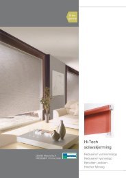
tende & scorritenda<br />
<strong>art</strong>. <strong>1805M35</strong><br />
MANUALE ISTRUZIONI MOTORE TUBOLARE ø35 mm - 220 V<br />
INSTRUCTION MANUAL FOR TUBULAR MOTOR ø35 mm - 220 V<br />
NOTICE D'INSTRUCTIONS MOTEUR TUBULAIRE ø35 mm - 220 V<br />
MANUAL DE INSTRUCCIONES MOTOR TUBULAR ø35 mm - 220 V<br />
BETRIEBSANLEITUNG ROHRMOTOR ø35 mm - 220 V<br />
INSTRUCTIEHANDLEIDING BUISMOTOR ø35 mm - 220 V<br />
Z 270_2 ed. 11/06
2/12<br />
CARACTERÍSTICAS TÉCNICAS<br />
A continuación se presentan las características<br />
técnicas del motor <strong>art</strong>. <strong>1805M35</strong>.<br />
• Tensión: 230 V<br />
• Frecuencia: 50 Hz<br />
• Corriente: 0,56 A<br />
• Potencia: 130 W<br />
• Par: 6 Nm<br />
• Revoluciones: 28 rpm<br />
• Capacidad final de carrera: 39 revoluciones<br />
• Diámetro: 35 mm<br />
• Tiempo de trabajo: 4 min<br />
• Grado de protección: IP44<br />
• Peso: 1,6 kg<br />
• Longitud cable de alimentación: 3 m<br />
Italiano<br />
DESCRIZIONE<br />
Il <strong>1805M35</strong> è un motore tubolare che da 35 mm di diametro (coppia di 6 Nm a<br />
28 rpm e finecorsa meccanici) che la Mottura ha sviluppato per i propri sistemi di<br />
tende a rullo.<br />
Il motore tubolare <strong>art</strong> <strong>1805M35</strong> può essere utilizzato nei sistemi con tubo in<br />
alluminio da Ø 40 mm e, attraverso l’applicazione degli appositi adattatori, con il<br />
tubo ad Ø 50 mm e con il tubo da Ø 60 mm.<br />
Il motore tubolare <strong>art</strong> <strong>1805M35</strong> è dotato di un finecorsa meccanico con una<br />
capacità di 39 giri e di una protezione termica che lo disattiva quando la temperatura<br />
raggiunge dei valori elevati.<br />
Français<br />
DESCRIPTION<br />
Le <strong>1805M35</strong> est un moteur tubulaire de 35 mm de diamètre (couple de 6 Nm<br />
à 28 tr/min et fins de course mécaniques) développé par Mottura pour ses propres<br />
systèmes de rideaux à rouleau.<br />
Le moteur tubulaire <strong>1805M35</strong> peut être utilisé dans les systèmes équipés de<br />
tubes en aluminium de Ø 40 mm et, après montage des adaptateurs spéciaux,<br />
avec le tube Ø 50 mm et le tube Ø 60 mm.<br />
Le moteur tubulaire <strong>1805M35</strong> est doté d'un fin de course mécanique d'une<br />
capacité de 39 tours et d'une protection thermique qui le désactive lorsque sa<br />
température atteint les valeurs maximales prévues.<br />
Deutsch<br />
BESCHREIBUNG<br />
Der <strong>1805M35</strong> ist ein Rohrmotor Durchm. 35 mm (Drehmoment 6 Nm bei 28<br />
U/min und mechanische Endanschläge), den Mottura für die eigenen Rollosysteme<br />
entwickelt hat.<br />
Der Rohrmotor Art. <strong>1805M35</strong> kann für Systeme mit Aluminium-Rohrwelle Ø 40<br />
mm und, unter Verwendung der entsprechenden Passelemente, mit der Rohrwelle<br />
Ø 50 mm und der Rohrwelle Ø 60 mm genutzt werden.<br />
Der Rohrmotor Art. <strong>1805M35</strong> ist mit einem mechanischen Endanschlag mit einer<br />
Kapazität von 39 Umdrehungen und einer Thermosicherung ausgestattet, die ihn<br />
bei überhöhten Temperaturen abschaltet.<br />
ISTRUZIONI IMPORTANTI PER LA SICUREZZA<br />
ATTENZIONE :<br />
• PER LA SICUREZZA DELLE PERSONE È IMPORTANTE SEGUIRE QUESTE<br />
ISTRUZIONI<br />
• L’INSTALLAZIONE NON CORRETTA PUÓ CAUSARE DANNI A COSE E<br />
PERSONE<br />
• SEGUIRE TUTTE LE ISTRUZIONI DI INSTALLAZIONE<br />
• CONSERVARE QUESTE ISTRUZIONI<br />
CONSIGNES DE SÉCURITÉ IMPORTANTES<br />
ATTENTION :<br />
• POUR GARANTIR LA SÉCURITÉ DES PERSONNES, IL EST IMPÉRATIF DE<br />
RESPECTER CES CONSIGNES DE SÉCURITÉ<br />
• UNE MAUVAISE INSTALLATION PEUT CAUSER DES DOMMAGES AUX<br />
PERSONNES ET AUX BIENS<br />
• SUIVRE SCRUPULEUSEMENT LES INSTRUCTIONS D’INSTALLATION<br />
• CONSERVER CES CONSIGNES<br />
WICHTIGE SICHERHEITSRELEVANTE ANWEISUNGEN<br />
ACHTUNG:<br />
• DIESE ANWEISUNGEN MÜSSEN ZUR GEWÄHRLEISTET DER SICHERHEIT<br />
DER PERSONEN UNBEDINGT BEFOLGT WERDEN<br />
• EINE UNSACHGEMÄSSE INSTALLATION KANN PERSONEN- UND<br />
SACHSCHÄDEN VERURSACHEN<br />
• ALLE MONTAGEANWEISUNGEN BEFOLGEN<br />
• DIESE ANWEISUNGEN AUFBEWAHREN<br />
Italiano<br />
CARATTERISTICHE TECNICHE<br />
Di seguito sono riportate le caratteristiche tecniche<br />
del motore <strong>art</strong>. <strong>1805M35</strong>.<br />
• Tensione: 230 V<br />
• Frequenza: 50 Hz<br />
• Corrente: 0,56 A<br />
• Potenza: 130 W<br />
• Coppia: 6 Nm<br />
• Giri: 28 rpm<br />
• Capacità finecorsa: 39 giri<br />
• Diametro: 35 mm<br />
• Tempo di lavoro: 4 min<br />
• Grado di protezione: IP44<br />
• Peso: 1,6 Kg<br />
• Lunghezza cavo di alimentazione: 3 m<br />
Español<br />
Z 270_2 - <strong>1805M35</strong> - ed. 11.06<br />
TECHNICAL SPECIFICATIONS<br />
The technical characteristcs of the <strong>art</strong>. <strong>1805M35</strong><br />
motor are described below.<br />
• Voltage: 230 V<br />
• Frequency: 50 Hz<br />
• Current: 0,56 A<br />
• Power: 130 W<br />
• Torque: 6 Nm<br />
• Revolutions: 28 rpm<br />
• Limit switch capacity: 39 turns<br />
• Diameter: 35 mm<br />
• Operating time: 4 min<br />
• Protection level: IP44<br />
• Weight: 1,6 Kg<br />
• Length of power lead: 3 m<br />
English<br />
DESCRIPTION<br />
The <strong>1805M35</strong> is a 35 mm diameter tubular motor (with 6 Nm torque at 28 rpm<br />
and mechanical limit stops) that Mottura has developed for its roller blind systems.<br />
The <strong>1805M35</strong> tubular motor can be used in systems with the Ø 40 mm aluminium<br />
tube and, by installing the appropriate adapters, with the Ø 50 mm tube and the<br />
Ø 60 mm tube.<br />
The <strong>1805M35</strong> tubular motor has a mechanical limit stop system with a capacity<br />
of 39 rpm and an overheat protection that switches it off at high temperatures.<br />
Español<br />
DESCRIPCIÓN<br />
El <strong>1805M35</strong> es un motor tubular de 35 mm de diámetro (par de 6 Nm a 28 r.p.m.<br />
y finales de carrera mecánicos) que Mottura ha desarrollado para sus propios<br />
sistemas de cortinas autoenrollables.<br />
El motor tubular <strong>art</strong>. <strong>1805M35</strong> puede utilizarse en los sistemas con tubo de<br />
aluminio de Ø 40 mm y, mediante la aplicación de adaptadores específicos, con<br />
el tubo de Ø 50 mm con el tubo de Ø 60 mm.<br />
El motor tubular <strong>art</strong>. <strong>1805M35</strong> está equipado con un final de carrera mecánico<br />
de 39 r.p.m. de capacidad y con una protección térmica encargada de desactivarlo<br />
cuando la temperatura alcanza valores elevados.<br />
Nederlands<br />
BESCHRIJVING<br />
De <strong>1805M35</strong> is een buismotor met een diameter van 35 mm (koppel van 6 Nm<br />
bij 28 tpm en mechanische eindschakelaars) die Mottura voor haar rolgordijnsystemen<br />
heeft ontwikkeld.<br />
De buismotor <strong>art</strong>. <strong>1805M35</strong> kan gebruikt worden in systemen met aluminium<br />
buis met Ø 40 mm en, door middel van toepassing van speciale adapters, met een<br />
buis met Ø 50 mm en met een buis met Ø 60 mm.<br />
De buismotor <strong>art</strong>. <strong>1805M35</strong> is voorzien van een mechanische eindschakelaar<br />
met een capaciteit van 39 omwentelingen en een thermische beveiliging waarmee<br />
hij uitgeschakeld worden als de temperatuur hoge waarden bereikt.<br />
Italiano English<br />
IMPORTANT SAFETY INSTRUCTIONS<br />
Français<br />
Deutsch<br />
English<br />
TECHNISCHE EIGENSCHAFTEN<br />
Nachstehend die technischen Merkmale des<br />
Motors Art. <strong>1805M35</strong>.<br />
• Spannung: 230 V<br />
• Frequenz: 50 Hz<br />
• Strom: 0,56 A<br />
• Leistung: 130 W<br />
• Drehmoment: 6 Nm<br />
• Drehzahl: 28 rpm<br />
• Stellbereich des Endschalters: 39 Umdrehungen<br />
• Durchmesser: 35 mm<br />
• Arbeitszeit: 4 Min.<br />
• Schutz<strong>art</strong>: IP44<br />
• Gewicht: 1,6 kg<br />
• Länge des Netzkabels: 3 m<br />
Deutsch<br />
Français<br />
CARACTÉRISTIQUES TECHNIQUES<br />
Caractéristiques techniques du moteur <strong>art</strong>.<br />
<strong>1805M35</strong> reportées ci-dessous.<br />
• Tension : 230 V<br />
• Fréquence : 50 Hz<br />
• Courant : 0,56 A<br />
• Puissance: 130 W<br />
• Couple : 6 Nm<br />
• Tours : 28 rpm<br />
• Capacité du fin de course : 39 tours<br />
• Diamètre : 35 mm<br />
• Temps de travail : 4 min<br />
• Indice de protection: IP44<br />
• Poids : 1,6 Kg<br />
• Longueur du câble d’alimentation: 3 m<br />
TECHNISCHE KENMERKEN<br />
Hieronder worden de technische kenmerken van<br />
de motor <strong>art</strong>. <strong>1805M35</strong> vermeld.<br />
• Spanning: 230 V<br />
• Frequentie: 50 Hz<br />
• Stroom: 0,56 A<br />
• Vermogen: 130 W<br />
• Koppel: 6 Nm<br />
• Omwentelingen: 28 rpm<br />
• Capaciteit eindschakelaar: 39 omwentelingen<br />
• Diameter: 35 mm<br />
• Werktijd: 4 min<br />
• Beveiligingsgraad: IP44<br />
• Gewicht: 1,6 kg<br />
• Lengte voedingskabel: 3 m<br />
CAUTION :<br />
• FOR PERSONAL SAFETY IT IS ESSENTIAL THAT THESE INSTRUCTIONS<br />
ARE FOLLOWED<br />
• INCORRECT INSTALLATION CAN CAUSE DAMAGE TO PERSONS AND<br />
PROPERTY<br />
• FOLLOW THE INSTALLATION INSTRUCTIONS CAREFULLY<br />
• KEEP THESE INSTRUCTIONS IN A SAFE PLACE<br />
INSTRUCCIONES IMPORTANTES PARA LA SEGURIDAD<br />
ATENCIÓN:<br />
• LA APLICACIÓN DE ESTAS INSTRUCCIONES ES DE FUNDAMENTAL<br />
IMPORTANCIA A FIN DE GARANTIZAR LA SEGURIDAD DE LAS PERSONAS<br />
• UNA INCORRECTA INSTALACIÓN PUEDE PROVOCAR LESIONES A LAS<br />
PERSONAS Y DAÑOS A LAS COSAS<br />
• APLICAR TODAS LAS INSTRUCCIONES RELATIVAS A LA INSTALACIÓN<br />
• CONSERVAR ESTAS INSTRUCCIONES<br />
BELANGRIJKE VEILIGHEIDSVOORSCHRIFTEN<br />
ATTENTIE :<br />
• VOOR DE VEILIGHEID VAN DE PERSONEN IS HET BELANGRIJK OM DEZE<br />
VOORSCHRIFTEN IN ACHT TE NEMEN<br />
• EEN NIET CORRECTE INSTALLATIE KAN SCHADE AAN ZAKEN EN LETSEL<br />
AAN PERSONEN VEROORZAKEN<br />
• VOLG ALLE INSTALLATIEVOORSCHRIFTEN<br />
• BEWAAR DEZE VOORSCHRIFTEN<br />
Nederlands<br />
Español<br />
Nederlands
3/12<br />
A B<br />
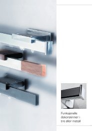
INSTALLAZIONE<br />
Il motore può essere installato nei sistemi:<br />
• Rollbox tramite l'applicazione del perno quadro 10x10 - (vedi disegno R) oppure<br />
tramite l'attacco diretto (vedi disegno D)<br />
• Energy tramite l’applicazione dell’<strong>art</strong>. 1836 – Flangia aggancio motore – (vedi<br />
disegno E)<br />
A seconda delle necessità, il motore e la tenda possono assumere una delle quattro<br />
configurazioni seguenti:<br />
configurazione figura<br />
Il motore, per funzionare correttamente, deve essere collegato e tarato in modo<br />
appropriato. A tale scopo fare riferimento a quanto riportato nella sezione “Collegamenti<br />
elettrici” e “Taratura finecorsa”.<br />
INSTALLATION<br />
Le moteur peut être installé dans les systèmes :<br />
• Rollbox après montage de la broche carrée 10x10 (voir dessin R) ou par fixation<br />
directe (voir dessin D)<br />
• Energy après montage de l'<strong>art</strong>. 1836 –Bride d'accrochage du moteur – (voir dessin E)<br />
En fonction des situations, le moteur et le rideau peuvent prendre l’une des quatre<br />
configurations suivantes:<br />
Pour fonctionner convenablement, le moteur doit être branché et réglé de façon<br />
correcte. Pour ce faire, consulter les sections «Branchements électriques» et «Réglage<br />
fin de cours»<br />
MONTAGE<br />
Der Motor kann in den folgenden Systemen installiert werden:<br />
• Rollbox unter Anwendung eines Vierkantstiftes 10x10 – (siehe Zeichnung R) oder<br />
als direkte Montage (siehe Zeichnung D)<br />
• Energy unter Anwendung von Art. 1836 – Motorbefestigungsflansch – (siehe<br />
Zeichnung E)<br />
Je nach Bedarf können der Motor und das Springrollo eine der vier nachstehenden<br />
Konfigurationen haben:<br />
konfiguration plan<br />
Damit der Motor einwandfrei funktionieren kann, muss er richtig angeschlossen<br />
und eingestellt werden. Siehe hierzu die Abschnitte "Elektrischer Anschluss" und<br />
"Einstellung des Endschalters".<br />
E<br />
R<br />
motore a sinistra / caduta telo posteriore A<br />
motore a destra / caduta telo anteriore B<br />
motore a sinistra / caduta telo anteriore C<br />
motore a destra / caduta telo posteriore D<br />
moteur à gauche / descente postérieure du rideau A<br />
moteur à droite / descente intérieure du rideau B<br />
moteur à gauche / descente intérieure du rideau C<br />
moteur à droite / descente postérieure du rideau D<br />
Motor links / Behang fällt hinten A<br />
Motor rechts / Behang fällt innen B<br />
Motor links / Behang fällt innen C<br />
Motor rechts / Behang fällt hinten D<br />
Energy 440-450<br />
configuration schéma<br />
Rollbox 465<br />
D<br />
R<br />
Z 270_2 - <strong>1805M35</strong> - ed. 11.06<br />
Rollbox 465<br />
Rollbox 475<br />
Italiano<br />
Français<br />
Deutsch<br />
D<br />
R<br />
C<br />
INSTALLATION<br />
The motor can be installed in the following systems:<br />
• Rollbox, by applying the 10x10 square pin (see drawing R) or with the direct<br />
attachment (see drawing D)<br />
• Energy, by installing <strong>art</strong>. 1836 – Motor attachment flange – (see drawing E)<br />
According to needs, the motor and the blind can have one of the following four<br />
configurations:<br />
motor on the left / blind drop to the rear A<br />
motor on the right / blind drop inside B<br />
motor on the left / blind drop inside C<br />
motor on the right / blind drop to the rear D<br />
To work properly the motor must be connected and calibrated appropriately. To do<br />
this refer to the information given in the “Electrical connections” and “Limit switch<br />
calibration” sections.<br />
INSTALACIÓN<br />
Este motor puede ser instalado en los sistemas:<br />
• Rollbox mediante la aplicación del perno cuadrado 10 x 10 (véase dibujo R) o<br />
mediante la conexión directa (véasedibujo D)<br />
• Energy mediante la aplicación de la brida de enganche motor, <strong>art</strong>. 1836 (véase dibujo E)<br />
En función de los específicos requerimientos, el motor y la cortina pueden asumir<br />
una de las siguientes cuatro configuraciones:<br />
configuración esquema<br />
motor a la izquierda / descenso tela trasero A<br />
motor a la derecha / descenso tela interior B<br />
motor a la izquierda / descenso tela interior C<br />
motor a la derecha / descenso tela trasero D<br />
A fin de que el motor funcione correctamente, deberá encontrarse conectado y<br />
calibrado de modo adecuado. Para ello, véanse las instrucciones de las secciones<br />
“Conexiones eléctricas” y “Calibración finales de carrera”.<br />
INSTALLATIE<br />
De motor kan geïnstalleerd worden in de systemen:<br />
• Rollbox d.m.v. toepassing van de vierkante pen 10x10 - (zie tekening R) of d.m.v<br />
de directe bevestiging (zie tekening D)<br />
• Energy d.m.v. toepassing van <strong>art</strong>. 1836 – Koppelflens motor – (zie tekening E)<br />
Afhankelijk van de behoeften, kunnen de motor en het gordijn een van de volgende<br />
vier configuraties aannemen:<br />
konfiguration plan<br />
motor links / doekval achter A<br />
motor rechts / doekval voor B<br />
motor links / doekval voor C<br />
motor rechts / doekval achter D<br />
De motor moet, om correct te kunnen werken, op de juiste manier worden aangesloten<br />
en afgesteld. Zie hiervoor hetgeen vermeld in de paragrafen “Elektrische aansluitingen”<br />
en “Instelling van de eindschakelaars”.<br />
Rollbox 485<br />
Rollbox 885<br />
Rollbox 485<br />
configuration diagram<br />
R<br />
R<br />
D<br />
English<br />
Español<br />
Nederlands<br />
Rollbox 885<br />
Rollbox 4115
4/12<br />
Italiano<br />
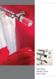
COLLEGAMENTI ELETTRICI<br />
Il motore tubolare è dotato di un cavo di alimentazione composto da 4 fili con i<br />
seguenti colori e funzioni.<br />
• Blu = Comune<br />
• Marrone = rotazione antioraria del motore (fig. X )<br />
• Nero = rotazione oraria del motore (fig. Y )<br />
• Giallo/verde = terra<br />
AVVERTENZE<br />
• Prima di installare il motore, rimuovere eventuali cavi preesistenti<br />
superflui e disabilitare eventuali apparecchiature non necessarie al suo<br />
funzionamento.<br />
• Non collegare mai due o più motori in parallelo sullo stesso scambio<br />
di un pulsante o sulla stessa uscita di una centralina <strong>art</strong>. 5064 o di<br />
un ricevitore <strong>art</strong>. 5158 (vedi fig. Z).<br />
• Dove è previsto l’utilizzo di pulsanti per il controllo diretto del motore<br />
(senza centralina), impiegare solo pulsanti tipo <strong>art</strong>. 5096 o <strong>art</strong>. 5097 -<br />
da 10A, a doppio contatto con interblocco e OFF centrale.<br />
• Per installazioni complesse contattare la Direzione Tecnica Mottura.<br />
Di seguito sono riportate alcune configurazioni ed i relativi schemi elettrici.<br />
English<br />
ELECTRICAL CONNECTIONS<br />
The tube motor is equipped with a power cable made up of 4 wires that have<br />
the following colours and functions.<br />
• Blue = Common<br />
• Brown = motor counter clockwise rotation (fig. X )<br />
• Black = motor clockwise rotation (fig. Y )<br />
• Yellow/green = e<strong>art</strong>h<br />
WARNINGS<br />
• Before installing the motor, remove any unnecessary existing wires<br />
and deactivate any equipment not needed for it to operate.<br />
• Never connect two or more motors in parallel on the same button<br />
exchange or on the same output of a control box <strong>art</strong>. 5064 or of a<br />
receiver <strong>art</strong>. 5158 (see fig. Z).<br />
• Where a button is used for direct motor control (no control box), use<br />
only <strong>art</strong>. 5096 or <strong>art</strong>. 5097 - buttons, 10A with two contacts, interlock<br />
and central OFF.<br />
• For complex installations contact the Mottura Technical Dep<strong>art</strong>ment.<br />
The following are some configurations and their relative wiring diagrams.<br />
Français<br />
BRANCHEMENTS ÉLECTRIQUES<br />
Le moteur tubulaire est muni d’un câble d’alimentation composé de 4 fils de<br />
couleurs et fonctions suivantes:<br />
• Bleu = Commun<br />
• Marron = rotation anti-horaire du moteur (fig. X )<br />
• Noir = rotation horaire du moteur (fig. Y )<br />
• Jaune/vert = terre<br />
AVERTISSEMENTS<br />
• Avant toute installation du moteur, retirer les câbles superflus et<br />
désactiver les appareillages ne servant pas à son fonctionnement.<br />
• Ne jamais brancher deux ou plusieurs moteurs en parallèle sur les<br />
mêmes contacts d’échange d'une touche ou sur la même sortie d’une<br />
centrale <strong>art</strong>. 5064 ou d’un récepteur <strong>art</strong>. 5158 ( voir fig. Z)<br />
• Lorsque l’installation prévoit l’utilisation de touches pour le contrôle<br />
direct du moteur (sans centrale), n’utiliser que des touches type <strong>art</strong>.<br />
5096 ou <strong>art</strong>. 5097 de 10A, à double contact sécurisé et OFF central.<br />
• Pour les installations complexes, contacter la Direction Technique<br />
Mottura.<br />
Plusieurs configurations, avec schémas électriques correspondants, sont reportées<br />
ci-après.<br />
Español<br />
CONEXIONES ELÉCTRICAS<br />
El motor tubular está provisto de un cable de alimentación compuesto por cuatro<br />
hilos con los siguientes colores y funciones.<br />
• Azul = común<br />
• Marrón = rotación antihoraria del motor (fig. X )<br />
• Negro = rotación horaria del motor (fig. Y )<br />
• Amarillo/verde = tierra<br />
ADVERTENCIAS<br />
• Antes de instalar el motor, retirar los cables preexistentes superfluos<br />
e inhabilitar los equipos que no sean necesarios para su funcionamiento.<br />
• No deberán conectarse nunca dos o más motores en paralelo en un<br />
mismo contacto de intercambio de un botón ni en la misma salida de<br />
una centralita <strong>art</strong>. 5064 o de un receptor <strong>art</strong>. 5158 (véase fig. Z).<br />
• En los casos en que está predispuesto el uso de botones para el<br />
control directo del motor (sin centralita), emplear únicamente botones<br />
tipo <strong>art</strong>. 5096 o <strong>art</strong>. 5097 - de 10 A, de doble contacto interbloqueado<br />
(que impide el cierre simultáneo de los dos contactos) y OFF central.<br />
• Para efectuar instalaciones complejas sírvase dirigirse a la Dirección<br />
Técnica Mottura.<br />
A continuación se presentan algunas configuraciones y sus respectivos esquemas<br />
eléctricos.<br />
Deutsch<br />
ELEKTRISCHER ANSCHLUSS<br />
Der Rohrmotor hat ein vieradriges Netzkabel, dessen Leitern die folgenden<br />
Farben und Funktionen haben:<br />
• Dunkelblau = gemeinsamer Leiter<br />
• Braun = Linkslauf des Motors (Abb. X )<br />
• Schwarz = Rechtslauf des Motors (Abb. Y )<br />
• Gelb-grün = Schutzleiter<br />
WARNUNG<br />
• Vor der Installation des Motors eventuell schon vorhandene, überflüssige<br />
Kabel entfernen und eventuell vorhandene Geräte, die nicht zu seinem<br />
Betrieb erforderlich sind, deaktivieren.<br />
• Keinesfalls zwei oder mehr Motoren parallel an denselben Wechselkontakt<br />
einer Taste bzw. an denselben Ausgang einer Steuereinheit Art. 5064<br />
oder eines Empfängers Art. 5158 anschließen (siehe Abb. Z).<br />
• Wenn die direkte Betätigung des Motors mit Tasten vorgesehen ist<br />
(ohne Steuereinheit), ausschließlich Tasten des Typs Art. 5096 oder Art.<br />
5097 mit Bemessungsstrom 10A, zwei verriegelten Kontakten und OFF<br />
in Mittelstellung verwenden.<br />
• Für komplexe Installtionen die Technische Direktion von Mottura zu<br />
Rate ziehen.<br />
Nachstehend sind einige Konfigurationen und die zugehörigen elektrischen<br />
Schaltpläne aufgeführt.<br />
Z 270_2 - <strong>1805M35</strong> - ed. 11.06<br />
Nederlands<br />
ELEKTRISCHE AANSLUITINGEN<br />
De buismotor is voorzien van een voedingskabel bestaande uit 4 draden met<br />
de volgende kleuren en functies.<br />
• Blauw = gemeenschappelijke draad<br />
• Bruin = rotatie linksom van de motor (fig. X )<br />
• Zw<strong>art</strong> = rotatie rechtsom van de motor (fig. Y )<br />
• Geel/groen = aarde<br />
WAARSCHUWINGEN<br />
• Verwijder, alvorens de motor te installeren, eventuele reeds bestaande,<br />
overbodige kabels en stel eventuele apparatuur die niet voor zijn werking<br />
nodig zijn buiten werking.<br />
• Sluit nooit twee of meerdere motoren parallel op hetzelfde wisselcontact<br />
van een drukknop of op dezelfde uitgang van een regeleenheid <strong>art</strong>. 5064<br />
of van een ontvanger <strong>art</strong>. 5158 aan (zie fig. Z).<br />
• Gebruik, daar waar het gebruik van drukknoppen voor de directe<br />
controle van de motor is voorzien (zonder regeleenheid), alleen<br />
drukknoppen van het type <strong>art</strong>. 5096 of <strong>art</strong>. 5097 - van 10A, met twee<br />
contacten met vergrendeling en middelste OFF.<br />
• Neem voor complexe installaties contact op met de Technische Directie<br />
van Mottura.<br />
Hieronder worden enkele configuraties en de betreffende elektrische schema’s<br />
weergegeven.<br />
220 Vac<br />
50 Hz<br />
N<br />
BLUE<br />
BLACK<br />
M<br />
L<br />
L1 L2<br />
BROWN<br />
X<br />
220 Vac<br />
50 Hz<br />
N<br />
BLUE<br />
L1 L2<br />
BLACK<br />
M<br />
L<br />
BROWN<br />
• BLACK / NERO / NOIR<br />
NEGRO / SCHWARZ / ZWART<br />
• BROWN / MARRONE / MARRON<br />
MARRÓN / BRAUN / BRUIN<br />
• BLUE / BLU / BLEU<br />
AZUL / BLAU / BLAUW<br />
220 Vac<br />
50 Hz<br />
Italiano<br />
PROTEZIONE TERMICA<br />
Il motore è dotato di una protezione termica che lo disattiva quando la temperatura<br />
raggiunge valori elevati. Allo scendere della temperatura, la protezione riattiva il motore<br />
rendendo nuovamente possibile il regolare funzionamento. Se, al riattivarsi del motore,<br />
l’alimentazione è ancora presente (es. pulsante premuto, segnale automantenuto da<br />
p<strong>art</strong>e delle centraline), il motore riprende a muoversi.<br />
I valori della protezione termica sono impostati in fabbrica e non sono modificabili.<br />
English<br />
THERMOSWITCH<br />
The motor is equipped with a thermoswitch that deactivates it when the temperature<br />
becomes too high. When the temperature drops again, the switch reactivates the motor<br />
once more making normal operation possible. When the motor is reactivated, if the<br />
power is still switched on (e.g. button pressed, signal auto-held by the control boxes),<br />
the motor will st<strong>art</strong> moving again.<br />
The thermoswitch values are factory preset and cannot be changed.<br />
Français<br />
PROTECTION THERMIQUE<br />
Le moteur est équipé d’une protection thermique qui le désactive automatiquement<br />
lorsque la température atteint une valeur trop élevée. Dès que la température redescend,<br />
la protection réactive le moteur et le met en condition de fonctionner normalement. Si,<br />
à la réactivation du moteur, l’alimentation est présente (ex. touche enfoncée, signal<br />
gardé par la centrale), le moteur s’actionne automatiquement.<br />
Les valeurs de la protection thermique sont paramétrées en usine et ne peuvent être<br />
modifiées.<br />
Español<br />
PROTECCIÓN TÉRMICA<br />
El motor está provisto de protección térmica que lo desactiva cuando la temperatura<br />
alcanza valores elevados. Al descender la temperatura, la protección reactiva el motor<br />
permitiendo nuevamente su regular funcionamiento. En caso de que al reactivarse el<br />
motor la alimentación se encuentre aún conectada (por ej. botón presionado, señal<br />
automantenido de p<strong>art</strong>e de las centralitas), el motor reanudará su funcionamiento.<br />
Los valores de la protección térmica son programados en fábrica y no pueden ser<br />
modificados.<br />
Deutsch<br />
THERMISCHER SCHUTZ<br />
Der Motor verfügt über einen thermischen Schutz, der ihn abschaltet, wenn seine<br />
Temperatur zu hoch ist. Nach dem Absinken der Temperatur schaltet die Schutzeinrichtung<br />
den Motor wieder ein, so dass er wieder normal funktioniert. Wenn bei der erneuten<br />
Einschaltung des Motors die Stromversorgung noch vorhanden ist (weil z.B. die Taste<br />
gedrückt ist; von den Steuereinheiten automatisch aufrechterhaltenes Signal), setzt<br />
sich der Motor wieder in Bewegung.<br />
Die Einstellung des thermischen Schutzes erfolgt im Werk und ist unveränderlich.<br />
Y<br />
N<br />
L<br />
Z<br />
Nederlands<br />
THERMISCHE BEVEILIGING<br />
De motor is voorzien van een thermische beveiliging, die hem inactiveert wanneer<br />
de temperatuur een hoge waarde bereikt. Zodra de temperatuur zakt, activeert de<br />
beveiliging de motor weer, zodat een normale werking kan worden hervat. Als bij het<br />
opnieuw activeren van de motor, de voeding nog aanwezig is (bijv. ingedrukte drukknop,<br />
signaal dat behouden wordt door de regeleenheden), begint de motor weer te bewegen.<br />
De waarden van de thermische beveiliging zijn in de fabriek afgesteld en kunnen<br />
niet gewijzigd worden.
5/12<br />
SINGOLO (CON PULSANTE ART. 5096)<br />
Questa configurazione è realizzata con un pulsante a singolo scambio con<br />
interblocco tipo <strong>art</strong>. 5096 e permette di azionare singolarmente un motore tubolare.<br />
Il motore è alimentato per tutto il tempo in cui il pulsante <strong>art</strong>. 5096 è premuto, al<br />
suo rilascio il motore si ferma<br />
Per i collegamenti fare riferimento alla tabella seguente.<br />
configurazione schema<br />
motore a sinistra / caduta telo posteriore<br />
motore a destra / caduta telo anteriore<br />
motore a sinistra / caduta telo anteriore<br />
motore a destra / caduta telo posteriore 2<br />
Avvertenza: Usare solo pulsanti tipo <strong>art</strong>. 5096 - da 10 A, singolo scambio a doppio<br />
contatto normalmente aperto (N.O.) con interblocco (posizione di OFF centrale).<br />
SINGLE (WITH ART. 5096 BUTTON)<br />
This configuration consists of a single exchange <strong>art</strong>. 5096 button with interlock<br />
and is used to activate a tube motor individually. The motor is supplied with power<br />
for as long as the <strong>art</strong>. 5096 button is pressed, it stops when it is released.<br />
For the connections see the table that follows.<br />
motor on the left / blind drop to the rear<br />
motor on the right / blind drop inside<br />
motor on the left / blind drop inside<br />
motor on the right / blind drop to the rear 2<br />
Warning: Use only <strong>art</strong>. 5096 buttons - 10 A, single exchange with double<br />
contacts normally open (N.O.) and interlocking (central OFF position).<br />
MANDO SINGULAR (MEDIANTE BOTÓN ART. 5096)<br />
Esta configuración, que es realizada mediante un botón de intercambio singular<br />
con interbloqueo tipo <strong>art</strong>. 5096, permite accionar singularmente un motor tubular.<br />
El motor es alimentado durante todo el tiempo en que el botón <strong>art</strong>. 5096 se mantiene<br />
presionado; esto significa que al soltar el botón, el motor se detiene.<br />
Para efectuar las conexiones tómese como referencia la siguiente tabla.<br />
configuración esquema<br />
motor a la izquierda / descenso tela trasero<br />
motor a la derecha / descenso tela interior<br />
motor a la izquierda / descenso tela interior<br />
motor a la derecha / descenso tela trasero 2<br />
Advertencia: Usar únicamente botones tipo <strong>art</strong>. 5096 - de 10 A, singular intercambio<br />
de doble contacto normalmente abierto (N.O.) con interbloqueo (posición de OFF central).<br />
Deutsch<br />
EINZELN (MIT TASTE ART. 5096)<br />
Diese Konfiguration sieht eine Taste mit einem einzelnen Wechselkontakt mit<br />
Verriegelung vom Typ Art. 5096 vor und gestattet die einzelne Betätigung eines<br />
Rohrmotors. Der Motor wird so lange gespeist, wie die Taste Art. 5096 gedrückt<br />
wird; er stoppt, wenn die Taste losgelassen wird.<br />
Für die Anschlüsse siehe die nachstehende Tabelle.<br />
konfiguration plan<br />
Motor links / Behang fällt hinten<br />
Motor rechts / Behang fällt innen<br />
configuration diagram<br />
Motor links / Behang fällt innen<br />
Motor rechts / Behang fällt hinten<br />
2<br />
Warnung: Ausschließlich Tasten des Typs Art. 5096 mit Bemessungsstrom 10A,<br />
einem Wechselkontakt mit zwei verriegelten Schließern (OFF in Mittelstellung) verwenden.<br />
Italiano<br />
NORME DI SICUREZZA<br />
• Il motore tubolare Mottura è stato sviluppato per essere utilizzato<br />
esclusivamente nei sistemi per tende a rullo. Ogni altra destinazione<br />
d’uso deve essere autorizzata dalla Mottura S.p.A.<br />
• Non lasciare che i bambini giochino con i comandi del sistema. A tale<br />
scopo posizionare i pulsanti e tenere eventuali radiocomandi lontano<br />
dalla loro portata.<br />
• Scollegare il motore dall’alimentazione quando si intendono eseguire<br />
operazioni di manutenzione (come la pulitura della finestra).<br />
• Far eseguire la posa del sistema e i collegamenti elettrici esclusivamente<br />
da personale specializzato.<br />
• È vietato intervenire sul sistema quando è alimentato. Prima di ogni<br />
intervento scollegare il motore dalla rete elettrica ed isolarlo per tutta la<br />
durata dell’intervento.<br />
• Verificare il corretto movimento della tenda finché non si è completamente<br />
fermata.<br />
• Controllate spesso che il sistema non abbia segni di usura o di<br />
danneggiamento dei cavi.<br />
• Nel caso in cui vengano riscontrati segni di usura o di danneggiamento<br />
dei cavi, non utilizzare il sistema e richiedere l’intervento del personale<br />
specializzato.<br />
1<br />
1<br />
Français<br />
INDIVIDUELLE (AVEC TOUCHE ART. 5096)<br />
Cette configuration est réalisée avec une touche à échange individuel sécurisé<br />
type <strong>art</strong>. 5096 et permet d’actionner individuellement un moteur tubulaire. Le moteur<br />
est alimenté tant que la touche <strong>art</strong>. 5096 est enfoncée et s’arrête lorsqu’elle il est<br />
relâchée.<br />
Pour les branchements, se reporter au tableau suivant.<br />
configuration schéma<br />
moteur à gauche / descente postérieure du rideau<br />
moteur à droite / descente intérieure du rideau<br />
moteur à gauche / descente intérieure du rideau<br />
moteur à droite / descente postérieure du rideau 2<br />
Avertissement: N’utiliser que des touches <strong>art</strong>. 5096 de 10A, à échange individuel<br />
à double contact normalement ouvert (N.O.) sécurisée (position de OFF centrale).<br />
Z 270_2 - <strong>1805M35</strong> - ed. 11.06<br />
1<br />
1<br />
1<br />
Italiano<br />
English<br />
Español<br />
L1 L2<br />
L<br />
L1<br />
L<br />
L2<br />
A B<br />
C<br />
C<br />
C<br />
M<br />
M<br />
BLUE<br />
BLUE<br />
D<br />
BROWN<br />
BLACK<br />
ART. 5096<br />
220 Vac<br />
50 Hz<br />
BLACK L1<br />
BROWN<br />
L2<br />
220 Vac<br />
50 Hz<br />
L1<br />
L2<br />
SAFETY RULES<br />
English<br />
• The Mottura tube motor has been designed to be used solely in<br />
roller blind systems. Any other use must be authorised by Mottura<br />
S.p.A.<br />
• Never allow small children to play with the system controls. For this<br />
reason locate buttons and keep all remote controls out of their reach.<br />
• Disconnect the motor that supplies the power when performing<br />
maintenance operations (such as cleaning the window).<br />
• Have the system and the electrical connections fitted by qualified<br />
technicians only.<br />
• It is forbidden to work on the system with the power switched on.<br />
Before any intervention disconnect the motor from the main electrical<br />
supply and keep it isolated during the whole operation.<br />
• Check that the blind moves correctly until it has stopped completely.<br />
• Make regular checks on the system for worn or damaged cables.<br />
• If the system is found to have worn or damaged cables, do not<br />
operate it but instead seek the assistance of a qualified technician.<br />
UP<br />
DOWN<br />
L1 - BLACK / NERO / NOIR / NEGRO / SCHWARZ / ZWART<br />
L2 - BROWN / MARRONE / MARRON / MARRÓN / BRAUN / BRUIN<br />
N - BLUE / BLU / BLEU / AZUL / BLAU / BLAUW<br />
L1 - BROWN / MARRONE / MARRON / MARRÓN / BRAUN / BRUIN<br />
L2 - BLACK / NERO / NOIR / NEGRO / SCHWARZ / ZWART<br />
N - BLUE / BLU / BLEU / AZUL / BLAU / BLAUW<br />
ENKELVOUDIG (MET DRUKKNOP ART. 5096)<br />
Deze configuratie is gerealiseerd met een drukknop met enkele wissel met<br />
vergrendeling type <strong>art</strong>. 5096 en zorgt voor enkelvoudige bediening van een buismotor.<br />
De motor wordt de gehele tijd dat de drukknop <strong>art</strong>. 5096 is ingedrukt gevoed en<br />
stopt pas bij het loslaten van de drukknop.<br />
Zie voor de aansluitingen de volgende tabel.<br />
konfiguration plan<br />
motor links / doekval achter<br />
motor rechts / doekval voor<br />
motor links / doekval voor<br />
motor rechts / doekval achter<br />
2<br />
Waarschuwing: Gebruik uitsluitend drukknoppen van het type <strong>art</strong>. 5096 - van 10 A,<br />
enkele wissel met dubbel maakcontact (N.O.) met vergrendeling (middelste OFF stand).<br />
N<br />
N<br />
L<br />
N<br />
L<br />
N<br />
L<br />
L<br />
1<br />
1<br />
2<br />
Nederlands
6/12<br />
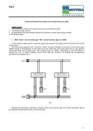
SINGOLO O GRUPPO (CON RICEVITORE R.F. ART. 5158)<br />
Questa configurazione è realizzata con il ricevitore R.F. <strong>art</strong>. 5158 e permette di<br />
comandare il motore singolarmente o in gruppo con altri prodotti della linea Domotic,<br />
sia via filo che via radio. Non collegare due o più motori in parallelo sulla stessa<br />
uscita di un ricevitore R.F. <strong>art</strong>. 5158.<br />
Il ricevitore R.F. <strong>art</strong>. 5158, al ricevere un comando, aziona per un determinato<br />
tempo il motore collegato senza che l’utilizzatore debba mantenere premuto il<br />
pulsante. Allo scadere del tempo impostato, il ricevitore R.F. <strong>art</strong>. 5158 toglie<br />
l’alimentazione al motore. Per ulteriori informazioni sul funzionamento e sulle<br />
impostazioni del ricevitore R.F. <strong>art</strong>. 5158 fare riferimento al relativo manuale tecnico.<br />
Per i collegamenti fare riferimento alla tabella seguente.<br />
configurazione schema<br />
motore a sinistra / caduta telo posteriore<br />
motore a destra / caduta telo anteriore<br />
motore a sinistra / caduta telo anteriore<br />
motore a destra / caduta telo posteriore<br />
SINGLE OR GROUP (WITH ART. 5158 R.F. RECEIVER)<br />
This configuration uses the <strong>art</strong>. 5158 R.F. receiver and allows the motor to be<br />
controlled either independently or in a group with other Domotic line products, both<br />
by cable and by radio. Do not connect two or more motors in parallel on the same<br />
output of an <strong>art</strong>. 5158 R.F. receiver.<br />
When a command is sent to the <strong>art</strong>. 5158 R.F. receiver, it activates the motor<br />
connected for a set time without the need for the user to keep the button pressed<br />
down. When the set time has elapsed, the <strong>art</strong>. 5158 R.F. receiver cuts off the power<br />
to the motor. For more information on how the <strong>art</strong>. 5158 R.F. receiver works and<br />
its settings, refer to the technical manual.<br />
For the connections see the table that follows.<br />
motor on the left / blind drop to the rear<br />
motor on the right / blind drop inside<br />
configuration diagram<br />
motor on the left / blind drop inside<br />
motor on the right / blind drop to the rear<br />
Français<br />
NORMES DE SECURITE<br />
• Le moteur tubulaire Mottura a été développé pour être utilisé<br />
exclusivement dans les systèmes pour rideaux à rouleaux. Toute autre<br />
utilisation doit faire l’objet d’une autorisation préalable écrite de Mottura<br />
S.p.A.<br />
• Ne pas laisser les enfants jouer avec les commandes du système. A<br />
ces fins, positionner les touchests et conserver les télécommandes hors<br />
de leur portée.<br />
• Débrancher le moteur d’alimentation avant toute opération d’entretien<br />
(ex. nettoyage de la fenêtre).<br />
• Ne confier la pose du système et les branchements électriques qu’à<br />
un personnel spécialisé.<br />
• Il est formellement interdit d’intervenir sur le système lorsqu’il est sous<br />
tension. Avant toute intervention, débrancher le moteur du secteur et<br />
l’isoler pendant toute la durée de l’intervention.<br />
• Vérifier que le mouvement du rideau ne rencontre pas de difficulté<br />
jusqu’à la fermeture complète.<br />
• Contrôler souvent que le système ne présente pas de signes d’usure<br />
ni d’endommagement des câbles.<br />
• En présence de signes d’usure ou d’endommagement des câbles, ne<br />
pas utiliser le système et contacter le personnel spécialisé.<br />
Z 270_2 - <strong>1805M35</strong> - ed. 11.06<br />
3<br />
4<br />
3<br />
4<br />
Italiano<br />
English<br />
Français<br />
INDIVIDUEL OU GROUPE (AVEC RECEPTEUR R.F. ART. 5158)<br />
Cette configuration utilise le récepteur R.F. <strong>art</strong>. 5158 et permet de commander<br />
le moteur individuellement ou en groupe avec d’autres produits de la ligne Domotic,<br />
par câble ou via radio. Ne pas brancher deux ou plusieurs moteurs en parallèle<br />
sur la même sortie d’un récepteur R.F. <strong>art</strong>. 5158.<br />
Lorsqu’il reçoit une commande, le récepteur R.F. 5158 actionne le moteur branché<br />
pendant un temps donné, sans qu’il soit nécessaire de maintenir la touche enfoncée.<br />
Au terme du temps paramétré, le récepteur R.F. <strong>art</strong>. 5158 coupe l’alimentation du<br />
moteur. Pour plus de détails sur le fonctionnement et les paramétrages du récepteur<br />
R.F. <strong>art</strong>. 5158, se reporter à la notice technique correspondante.<br />
Pour les branchements, se reporter au tableau suivant.<br />
configuration schéma<br />
moteur à gauche / descente postérieure du rideau<br />
moteur à droite / descente intérieure du rideau<br />
moteur à gauche / descente intérieure du rideau<br />
moteur à droite / descente postérieure du rideau<br />
Español<br />
SINGULAR O EN GRUPO (MEDIANTE RECEPTOR R.F. ART. 5158)<br />
Esta configuración, que es realizada mediante el receptor R.F. <strong>art</strong>. 5158, permite<br />
gobernar el motor singularmente o de modo simultáneo con otros productos de la línea<br />
Domotic, tanto vía hilo como vía radio. No conectar dos o más motores en paralelo en<br />
la misma salida de un receptor R.F. <strong>art</strong>. 5158.<br />
Al recibir un mando, el receptor R.F. <strong>art</strong>. 5158 acciona durante un determinado lapso<br />
el motor conectado sin que el usuario deba mantener presionado el botón. Al cumplirse<br />
el tiempo programado, el receptor R.F. <strong>art</strong>. 5158 interrumpe la alimentación al motor.<br />
Para mayores informaciones acerca del funcionamiento y de las programaciones del<br />
receptor R.F. <strong>art</strong>. 5158 sírvase consultar el respectivo manual técnico.<br />
Para efectuar las conexiones tómese como referencia la siguiente tabla.<br />
configuración esquema<br />
motor a la izquierda / descenso tela trasero<br />
motor a la derecha / descenso tela interior<br />
motor a la izquierda / descenso tela interior<br />
motor a la derecha / descenso tela trasero<br />
3<br />
4<br />
3<br />
4<br />
A B<br />
220 Vac<br />
50 Hz<br />
C<br />
Art.<br />
5158<br />
LINE<br />
J1 L N<br />
L<br />
N<br />
OUT<br />
C<br />
COMANDO<br />
SINGOLO<br />
<strong>art</strong>. 5151<br />
<strong>art</strong>. 5096<br />
Deutsch<br />
EINZELN ODER GRUPPE (MIT FUNKEMPFÄNGER ART. 5158)<br />
Diese Konfiguration wird mit dem Funkempfänger Art. 5158 realisiert und gestattet<br />
die einzelne Betätigung eines Motors oder zusammen mit anderen Produkten der Linie<br />
Domotic sowohl über Kabel als auch per Funk. Keinesfalls zwei oder mehr Motoren<br />
parallel an denselben Ausgang eines Funkempfängers Art. 5158 anschließen.<br />
Bei Empfang eines Befehls betätigt der Funkempfänger Art. 5158 den angeschlossenen<br />
Motor für eine bestimmte Zeit, ohne dass der Benutzer die Taste gedrückt halten muss.<br />
Nach Ablauf der eingestellten Zeit unterbricht der Funkempfänger Art. 5158 die<br />
Stromversorgung des Motors. Für weitere Informationen zur Funktionsweise und zu den<br />
Einstellungen des Funkempfängers Art. 5158 siehe das zugehörige technische Handbuch.<br />
Für die Anschlüsse siehe die nachstehende Tabelle.<br />
Motor links / Behang fällt hinten<br />
Motor rechts / Behang fällt innen<br />
Motor links / Behang fällt innen<br />
Motor rechts / Behang fällt hinten<br />
Konfiguration Plan<br />
ENKELVOUDIG OF GROEP (MET RF-ONTVANGER ART. 5158)<br />
Deze configuratie is gerealiseerd met de RF-ontvanger <strong>art</strong>. 5158 en zorgt voor<br />
afzonderlijke bediening van de motor of samen met andere producten van het<br />
Domotic gamma, zowel via draad als via radio. Sluit niet twee of meerdere motoren<br />
in parallel op dezelfde uitgang van een RF-ontvanger <strong>art</strong>. 5158 aan.<br />
De RF-ontvanger <strong>art</strong>. 5158 bedient, bij ontvangst van een commando, voor een<br />
bepaalde tijd de aangesloten motor zonder dat de gebruiker de drukknop ingedrukt<br />
hoeft te houden. De RF-ontvanger <strong>art</strong>. 5158 onttrekt voeding aan de motor bij het<br />
verstrijken van de ingestelde tijd. Zie de betreffende technische handleiding voor<br />
meer informatie over de werking en de instellingen van de RF-ontvanger <strong>art</strong>. 5158.<br />
Zie voor de aansluitingen de volgende tabel.<br />
motor links / doekval achter<br />
motor rechts / doekval voor<br />
C J2<br />
motor links / doekval voor<br />
motor rechts / doekval achter<br />
C<br />
DOWN<br />
COM<br />
UP<br />
BROWN<br />
BLACK<br />
BLUE<br />
M<br />
3<br />
- BROWN / MARRONE / MARRON /<br />
MARRÓN / BRAUN / BRUIN<br />
- BLACK / NERO / NOIR /<br />
NEGRO / SCHWARZ / ZWART<br />
- BLUE / BLU / BLEU /<br />
AZUL / BLAU / BLAUW<br />
C<br />
220 Vac<br />
50 Hz<br />
C<br />
Art.<br />
5158<br />
LINE<br />
J1 L N<br />
Español<br />
NORMAS DE SEGURIDAD<br />
• El motor tubular Mottura ha sido desarrollado para ser utilizado<br />
únicamente en los sistemas para cortinas de rodillo. Todo otro uso al<br />
que se lo destine deberá ser previamente autorizado por Mottura S.p.A.<br />
• Impedir que los niños jueguen con los mandos del sistema. Para ello<br />
se deberán colocar los botones y mantener los radiomandos lejos del<br />
alcance de los niños.<br />
• Desconectar el motor respecto de la alimentación antes de efectuar<br />
operaciones de mantenimiento (tales como la limpieza de la ventana).<br />
• La instalación del sistema y las conexiones eléctricas deberán ser<br />
efectuadas única y exclusivamente por personal especializado.<br />
• Está terminantemente prohibido intervenir en el sistema cuando el<br />
mismo está siendo alimentado. Antes de cada intervención desconectar<br />
el motor respecto de la red eléctrica y mantenerlo aislado durante toda<br />
la ejecución de la intervención.<br />
• Controlar el correcto movimiento de la cortina hasta que se haya<br />
detenido por completo.<br />
• Controlar regularmente que el sistema no presente señales de desgaste<br />
ni daños en los cables.<br />
• En caso de detectarse señales de desgaste o de daños de los cables<br />
no utilizar el sistema y solicitar la intervención de personal especializado.<br />
L<br />
N<br />
OUT<br />
C<br />
COMANDO<br />
SINGOLO<br />
3<br />
4<br />
Konfiguration Plan<br />
C J2<br />
BLACK<br />
BROWN<br />
BLUE<br />
3<br />
4<br />
<strong>art</strong>. 5151<br />
<strong>art</strong>. 5096<br />
C<br />
DOWN<br />
COM<br />
UP<br />
M<br />
4<br />
- BLACK / NERO / NOIR /<br />
NEGRO / SCHWARZ / ZWART<br />
- BROWN / MARRONE / MARRON /<br />
MARRÓN / BRAUN / BRUIN<br />
- BLUE / BLU / BLEU /<br />
AZUL / BLAU / BLAUW<br />
D<br />
Nederlands
7/12<br />
GRUPPO DI PIÙ MOTORI (CON CENTRALINA ART. 5064)<br />
Questa configurazione è realizzata con l’impiego della centralina <strong>art</strong>. 5064 e<br />
permette di azionare, a seconda delle versioni, simultaneamente 4, 8 o 12 motori.<br />
Con questa configurazione non è possibile comandare singolarmente uno dei<br />
motori colleganti. Non collegare due o più motori in parallelo sulla stessa uscita<br />
(vedi fig. Z). Per ulteriori informazioni sul funzionamento e sulle impostazioni della<br />
centralina <strong>art</strong>. 5064 fare riferimento al relativo manuale tecnico.<br />
Per i collegamenti fare riferimento alla tabella seguente.<br />
motore a sinistra / caduta telo posteriore<br />
motore a destra / caduta telo anteriore<br />
configurazione schema<br />
motore a sinistra / caduta telo anteriore<br />
motore a destra / caduta telo posteriore<br />
GROUP OF MORE THAN ONE MOTOR (WITH ART. 5064 CONTROL BOX)<br />
This configuration uses the <strong>art</strong>. 5064 control box and, depending on the version,<br />
allows 4, 8 or 12 motors to be activated simultaneously. With this configuration it<br />
is not possible to activate one of the inter-connecting motors separately. Do not<br />
connect two or more motors in parallel on the same output (see fig. Z). For more<br />
information on how the <strong>art</strong>. 5064 control box works and its settings, refer to the<br />
technical manual.<br />
For the connections see the table that follows.<br />
configuration diagram<br />
motor on the left / blind drop to the rear<br />
motor on the right / blind drop inside<br />
motor on the left / blind drop inside<br />
motor on the right / blind drop to the rear<br />
Français<br />
GROUPE DE PLUSIEURS MOTEURS (AVEC CENTRALE ART. 5064)<br />
Cette configuration utilise la centrale <strong>art</strong>. 5064 et permet d’actionner, en fonction<br />
des versions, simultanément 4, 8 ou 12 moteurs. Avec cette configuration, il n’est<br />
pas possible de commander individuellement un seul des moteurs. Ne pas brancher<br />
deux ou plusieurs moteurs en parallèle sur la même sortie (voir fig. Z). Pour plus<br />
de détails sur le fonctionnement et les paramétrages de la centrale <strong>art</strong>. 5064, se<br />
reporter à la notice technique correspondante.<br />
Pour les branchements, se reporter au tableau suivant.<br />
configuration schéma<br />
moteur à gauche / descente postérieure du rideau<br />
moteur à droite / descente intérieure du rideau<br />
moteur à gauche / descente intérieure du rideau<br />
moteur à droite / descente postérieure du rideau<br />
Español<br />
GRUPO DE VARIOS MOTORES (CON CENTRALITA ART. 5064)<br />
Esta configuración se realiza con el empleo de la centralita <strong>art</strong>. 5064 y, según la<br />
versión específica, permite accionar simultáneamente 4, 8 ó 12 motores. Con esta<br />
configuración no es posible gobernar singularmente uno de los motores conectados.<br />
No conectar dos o más motores en paralelo en la misma salida (véase fig. Z). Para<br />
mayores informaciones acerca del funcionamiento y de las programaciones de la<br />
centralita <strong>art</strong>. 5064 sírvase consultar el respectivo manual técnico.<br />
Para efectuar las conexiones tómese como referencia la siguiente tabla.<br />
configuración esquema<br />
motor a la izquierda / descenso tela trasero<br />
motor a la derecha / descenso tela interior<br />
motor a la izquierda / descenso tela interior<br />
motor a la derecha / descenso tela trasero<br />
GRUPPE AUS MEHREREN MOTOREN (MIT STEUEREINHEIT ART. 5064)<br />
Diese Konfiguration wird mit der Steuereinheit Art. 5064 realisiert und gestattet<br />
je nach Version die gleichzeitige Betätigung von 4, 8 oder 12 Motoren. Bei dieser<br />
Konfiguration können die angeschlossenen Motoren nicht einzeln betätigt werden.<br />
Keinesfalls zwei oder mehr Motoren parallel an denselben Ausgang anschließen<br />
(siehe Abb. Z). Für weitere Informationen zur Funktionsweise und zu den Einstellungen<br />
der Steuereinheit Art. 5064 siehe das zugehörige technische Handbuch.<br />
Für die Anschlüsse siehe die nachstehende Tabelle.<br />
konfiguration plan<br />
Motor links / Behang fällt hinten<br />
Motor rechts / Behang fällt innen<br />
Motor links / Behang fällt innen<br />
Motor rechts / Behang fällt hinten<br />
5<br />
6<br />
5<br />
6<br />
5<br />
6<br />
5<br />
6<br />
5<br />
6<br />
Italiano<br />
English<br />
Deutsch<br />
Deutsch<br />
SICHERHEITSVORSCHRIFTEN<br />
• Der Rohrmotor von Mottura wurde ausschließlich für den Einsatz in<br />
den Springrollosystemen konzipiert. Jeder andere Zweckbestimmung<br />
muss von Mottura genehmigt werden.<br />
• Die Bedieneinrichtungen des Systems dürfen nicht von Kindern zum<br />
Spielen benutzt werden. Daher müssen die Tasten außerhalb der<br />
Reichweite von Kindern positioniert und die eventuellen Fernbedienungen<br />
vor ihrem Zugriff geschützt aufbewahrt werden.<br />
• Wenn W<strong>art</strong>ungsarbeiten ausgeführt werden müssen (z.B. Fensterputzen),<br />
den Motor von der Stromversorgung trennen.<br />
• Den Einbau des Systems und die elektrischen Anschlüsse ausschließlich<br />
vom Fachmann ausführen lassen.<br />
• Es ist verboten, Eingriffe am System vorzunehmen, wenn es an die<br />
Stromversorgung angeschlossen ist. Vor jedem Eingriff den Motors vom<br />
Stromnetz trennen und für die ganze Dauer des Eingriffs isolieren.<br />
• Sicherstellen, dass sich das Springrollo bis zum völligen Stillstand<br />
einwandfrei bewegt.<br />
• Häufig kontrollieren, ob das System Verschleißerscheinungen aufweist<br />
und ob die Kabel beschädigt sind.<br />
• Wenn Zeichen von Verschleiß oder Schäden an den Kabeln festgestellt<br />
werden, das System nicht verwenden, sondern vom Fachmann reparieren<br />
lassen.<br />
Z 270_2 - <strong>1805M35</strong> - ed. 11.06<br />
A B A B<br />
C<br />
M BROWN<br />
BLACK<br />
<strong>art</strong>. 5096<br />
N<br />
L2<br />
L1<br />
GROEP VAN MEERDERE MOTOREN (MET REGELEENHEID ART. 5064)<br />
Deze configuratie is gerealiseerd met toepassing van de regeleenheid <strong>art</strong>. 5064<br />
en zorgt voor gelijktijdige bediening van 4, 8 of 12 motoren, afhankelijk van de<br />
versie. Met deze configuratie kunnen de aangesloten motoren niet afzonderlijk<br />
bediend worden. Sluit niet twee of meerdere motoren in parallel op dezelfde uitgang<br />
aan (zie fig. Z). Zie de betreffende technische handleiding voor meer informatie<br />
over de werking en de instellingen van de regeleenheid <strong>art</strong>. 5064.<br />
Zie voor de aansluitingen de volgende tabel.<br />
konfiguration plan<br />
motor links / doekval achter<br />
motor rechts / doekval voor<br />
motor links / doekval voor<br />
motor rechts / doekval achter<br />
5<br />
L1 - BLACK / NERO / NOIR / NEGRO / SCHWARZ / ZWART<br />
L2 - BROWN / MARRONE / MARRON / MARRÓN / BRAUN / BRUIN<br />
C N - BLUE / BLU / BLEU / AZUL / BLAU / BLAUW<br />
M<br />
BLUE<br />
BLUE<br />
BLACK<br />
BROWN<br />
<strong>art</strong>. 5096<br />
C<br />
C<br />
N<br />
L2<br />
D<br />
L1<br />
<strong>art</strong>. 5064/...<br />
6<br />
<strong>art</strong>. 5064/...<br />
L1<br />
L2<br />
N<br />
L<br />
N<br />
BLACK<br />
BROWN<br />
BLUE<br />
BROWN<br />
BLACK<br />
220 Vac<br />
50 Hz<br />
BLUE<br />
L1 - BROWN / MARRONE / MARRON / MARRÓN / BRAUN / BRUIN<br />
L2 - BLACK / NERO / NOIR / NEGRO / SCHWARZ / ZWART<br />
C N - BLUE / BLU / BLEU / AZUL / BLAU / BLAUW<br />
C<br />
L1<br />
L2<br />
N<br />
L<br />
N<br />
220 Vac<br />
50 Hz<br />
5<br />
6<br />
M<br />
D<br />
M<br />
Nederlands<br />
Nederlands<br />
VEILIGHEIDSVOORSCHRIFTEN<br />
• De buismotor Mottura is ontwikkeld om uitsluitend gebruikt te worden<br />
voor systemen met rolgordijnen. Elke andere gebruiksbestemming moet<br />
door Mottura S.p.A. goedgekeurd worden.<br />
• Laat kinderen niet met de bedieningsorganen van het systeem spelen.<br />
Plaats met het oog hierop de drukknoppen uit hun buurt en houd<br />
eventuele afstandsbedieningen ook buiten hun bereik.<br />
•Koppel de motor van de stroomvoorziening af als men<br />
onderhoudswerkzaamheden wil uitvoeren (bijvoorbeeld het schoonmaken<br />
van het venster).<br />
• Laat het systeem en de elektrische aansluitingen uitsluitend door<br />
gespecialiseerd personeel aanleggen.<br />
• Zit niet aan het systeem terwijl het gevoed is. Koppel vóór het uitvoeren<br />
van werkzaamheden de motor van het elektriciteitsnet af en isoleer hem<br />
gedurende de werkzaamheden.<br />
• Controleer de correcte beweging van het gordijn tot en met de volledige<br />
stop.<br />
• Controleer dikwijls of de kabels van het systeem niet versleten of<br />
beschadigd zijn.<br />
• Indien versleten of beschadigde kabels worden geconstateerd, mag<br />
het systeem niet gebruikt worden en moet de hulp van gespecialiseerd<br />
personeel worden ingeroepen.
8/12<br />
GRUPPO DI DUE MOTORI (CON PULSANTE ART. 5097)<br />
Questa configurazione è realizzata con un pulsante a doppio scambio con interblocco<br />
tipo <strong>art</strong>. 5097 e permette di azionare simultaneamente due motori. I due motori sono<br />
alimentati per tutto il tempo in cui il pulsante <strong>art</strong>. 5097 è premuto, al suo rilascio i motori<br />
si fermano. Con questa configurazione non è possibile azionare singolarmente uno dei<br />
due motori. Non collegare due o più motori in parallelo sullo stesso scambio (vedi fig. Z).<br />
Per i collegamenti fare riferimento alla tabella seguente.<br />
motore a sinistra / caduta telo posteriore<br />
motore a destra / caduta telo anteriore<br />
TWO-MOTOR GROUP (WITH ART. 5097 BUTTON)<br />
This configuration consists of a double exchange <strong>art</strong>. 5097 button with interlock and<br />
is used to activate two motors at the same time. The two motors are supplied with power<br />
for as long as the <strong>art</strong>. 5097 button is pressed, and they stop when it is released. With<br />
this configuration it is not possible to activate one of the two motors separately. Do not<br />
connect two or more motors in parallel on the same exchange (see fig. Z).<br />
For the connections see the table that follows.<br />
motor on the left / blind drop to the rear<br />
motor on the right / blind drop inside<br />
configurazione schema<br />
motore a sinistra / caduta telo anteriore<br />
motore a destra / caduta telo posteriore<br />
Avvertenza: Usare solo pulsanti tipo <strong>art</strong>. 5097 - da 10 A, doppio scambio a doppio<br />
contatto normalmente aperto (N.O.) con interblocco (posizione di OFF centrale).<br />
configuration diagram<br />
motor on the left / blind drop inside<br />
motor on the right / blind drop to the rear<br />
Warnings: Use only <strong>art</strong>. 5097 buttons - 10 A, double exchange with double contacts<br />
normally open (N.O.) and interlock (central OFF position).<br />
GROUPE DE DEUX MOTEURS (AVEC TOUCHE ART. 5097)<br />
Cette configuration est réalisée avec une touche à double échange sécurisé type <strong>art</strong>.<br />
5097 et permet d’actionner simultanément deux moteurs. Les deux moteurs sont alimentés<br />
tant que la touche <strong>art</strong>. 5097 est enfoncé et s’arrêtent lorsqu’elle est relâchée. Avec cette<br />
configuration, il n’est pas possible d’actionner individuellement un seul des deux moteurs.<br />
Ne pas brancher deux ou plusieurs moteurs en parallèle sur les contacts du même<br />
échange (voir fig. Z).<br />
Pour les branchements, se reporter au tableau suivant.<br />
configuration schéma<br />
moteur à gauche / descente postérieure du rideau<br />
moteur à droite / descente intérieure du rideau<br />
moteur à gauche / descente intérieure du rideau<br />
moteur à droite / descente postérieure du rideau<br />
Avertissement: N’utiliser que des touches <strong>art</strong>. 5097 de 10A, à double échange et<br />
double contact normalement ouvert (N.O.) sécurisé (position de OFF centrale).<br />
7<br />
8<br />
7<br />
8<br />
7<br />
8<br />
Italiano<br />
English<br />
Français<br />
GRUPO DE DOS MOTORES (MEDIANTE BOTÓN ART. 5097)<br />
Esta configuración, que es realizada mediante un botón de doble intercambio con<br />
interbloqueo tipo <strong>art</strong>. 5097, permite accionar simultáneamente dos motores. Los dos<br />
motores son alimentados durante todo el tiempo en que el botón <strong>art</strong>. 5097 se mantiene<br />
presionado; al soltarlo los motores se detienen. Con esta configuración no es posible<br />
accionar singularmente uno de los dos motores. No conectar dos o más motores en<br />
paralelo en el mismo intercambio (véase fig. Z).<br />
Para efectuar las conexiones tómese como referencia la siguiente tabla.<br />
configuración esquema<br />
motor a la izquierda / descenso tela trasero<br />
motor a la derecha / descenso tela interior<br />
motor a la izquierda / descenso tela interior<br />
motor a la derecha / descenso tela trasero<br />
Advertencia: Usar únicamente botones tipo <strong>art</strong>. 5097 - de 10 A, doble intercambio de doble<br />
contacto normalmente abierto (N.O.) con interbloqueo (posición de OFF central).<br />
7<br />
8<br />
Español<br />
GRUPPE AUS ZWEI MOTOREN (MIT TASTE ART. 5097)<br />
Diese Konfiguration sieht eine Taste mit zwei Wechselkontakten mit Verriegelung vom<br />
Typ Art. 5097 vor und gestattet die gleichzeitige Betätigung von zwei Motoren. Die beiden<br />
Motoren werden so lange gespeist, wie die Taste Art. 5097 gedrückt wird; sie stoppen,<br />
wenn die Taste losgelassen wird. Bei dieser Konfiguration können die Motoren nicht<br />
einzeln betätigt werden. Keinesfalls zwei oder mehr Motoren an denselben Wechselschalter<br />
anschließen (siehe Abb. Z).<br />
Für die Anschlüsse siehe die nachstehende Tabelle.<br />
konfiguration plan<br />
Motor links / Behang fällt hinten<br />
Motor rechts / Behang fällt innen<br />
Motor links / Behang fällt innen<br />
Motor rechts / Behang fällt hinten<br />
Warnung: Ausschließlich Tasten des Typs Art. 5097 mit Bemessungsstrom 10A, zwei<br />
Wechselkontakten mit zwei verriegelten Schließern (OFF in Mittelstellung) verwenden.<br />
Z 270_2 - <strong>1805M35</strong> - ed. 11.06<br />
7<br />
8<br />
Deutsch<br />
L1A L2A L1B L2B<br />
A<br />
LA<br />
220 Vac<br />
50 Hz<br />
LB<br />
B<br />
L<br />
N<br />
A B<br />
L1A L1B<br />
LA<br />
LB<br />
L2A L2B<br />
BLACK<br />
BROWN<br />
ART. 5097<br />
7<br />
L1A L2A L1B L2B<br />
A B<br />
LA LB<br />
BLUE<br />
<strong>art</strong>.<br />
5097<br />
UP<br />
DOWN<br />
A B A B<br />
BLACK<br />
BROWN<br />
M M<br />
BLUE<br />
BLUE<br />
L1A/L1B - BLACK / NERO / NOIR / NEGRO / SCHWARZ / ZWART<br />
L2A/L2B - BROWN / MARRONE / MARRON / MARRÓN / BRAUN / BRUIN<br />
C N - BLUE / BLU / BLEU / AZUL / BLAU / BLAUW<br />
220 Vac<br />
50 Hz<br />
L<br />
N<br />
BROWN<br />
BLACK<br />
8<br />
C D<br />
C<br />
D<br />
L1A L2A L1B L2B<br />
A B<br />
LA LB<br />
BLUE<br />
<strong>art</strong>.<br />
5097<br />
BROWN<br />
BLACK<br />
M M<br />
BLUE<br />
BLUE<br />
L1A/L1B - BROWN / MARRONE / MARRON / MARRÓN / BRAUN / BRUIN<br />
L2B/L2B - BLACK / NERO / NOIR / NEGRO / SCHWARZ / ZWART<br />
C N - BLUE / BLU / BLEU / AZUL / BLAU / BLAUW<br />
GROEP VAN TWEE MOTOREN (MET DRUKKNOP ART. 5097)<br />
Deze configuratie is gerealiseerd met een drukknop met dubbele wissel met<br />
vergrendeling type <strong>art</strong>. 5097 en kan gelijktijdig twee motoren bedienen. De twee motoren<br />
worden gedurende de tijd dat de drukknop <strong>art</strong>. 5097 wordt ingedrukt gevoed en stoppen<br />
wanneer de drukknop wordt losgelaten. Met deze configuratie kan een van beide motoren<br />
afzonderlijk bediend worden. Sluit niet twee of meerdere motoren in parallel op dezelfde<br />
schakelaar aan (zie fig. Z).<br />
Zie voor de aansluitingen de volgende tabel.<br />
konfiguration plan<br />
motor links / doekval achter<br />
motor rechts / doekval voor<br />
motor links / doekval voor<br />
motor rechts / doekval achter<br />
8<br />
Waarschuwing: Gebruik uitsluitend drukknoppen van het type <strong>art</strong>. 5097 - van 10 A, dubbele<br />
wissel met dubbel maakcontact (N.O.) met vergrendeling (middelste OFF stand).<br />
Prodotto conforme alla Direttiva CEE n° 89/336 e Direttiva CEE n° 73/23<br />
Product in conformity with EEC Directive no. 89/336 and EEC Directive no. 73/23<br />
Produit conforme a la Dircetive CEE n° 89/336 e la Directive CEE n° 73/23<br />
Producto conforme con lo disquesto por la Directiva CEE n° 89/336 y por la Directiva CEE n° 73/23<br />
Produkt entspricht der EWG-Richtlinie 89/336 sowie der EWG-Richtlinie 73/23<br />
Product in overeenstemming met de EEG richtlijn nr. 89/336 en de EEG Richtlijn nr. 73/23<br />
7<br />
Nederlands
9/12<br />
Italiano<br />
TARATURA FINECORSA<br />
Il motore è dotato di due finecorsa, uno per l’arresto “Superiore” e<br />
uno per “Inferiore”. Entrambi i finecorsa sono posizionati nella testata<br />
del motore e sono caratterizzati da viti che ne permettono la regolazione<br />
tramite la chiave esagonale in dotazione o una chiave a brugola da<br />
4 mm. Accanto alla vite di ogni finecorsa è presente una freccia che<br />
indica il senso di rotazione da lui controllato.<br />
A seconda di come viene posizionato il motore all’interno del sistema,<br />
i finecorsa assumono un significato diverso. Pertanto occorre ricordare<br />
la regola:<br />
• il finecorsa “Superiore” è sempre quello con la freccia che indica la<br />
direzione in cui il motore avvolge telo.<br />
• il finecorsa “Inferiore” è sempre quello con la freccia che indica la<br />
direzione in cui il motore svolge il telo.<br />
Identificato il finecorsa da regolare, agire sulla sua vite in direzione:<br />
“-” = riduce la corsa<br />
“+” = aumenta la corsa<br />
ATTENZIONE!!<br />
Il mancato rispetto delle procedure può causare danni al sistema, a<br />
cose e a persone. Leggere attentamente quanto riportato o far eseguire<br />
la taratura dei finecorsa da personale specializzato.<br />
AVVERTENZE<br />
Nel caso in cui l’installazione preveda l’alimentazione del motore tramite:<br />
• una centralina<br />
• un ricevitore radio<br />
• una unità di Home e Building Automation<br />
l’operazione di taratura non deve essere eseguita utilizzando queste<br />
apparecchiature perché il loro comando è di tipo automantenuto e non<br />
impulsivo (ciò potrebbe causare danni irreparabili al sistema).<br />
Eseguire le operazioni di taratura esclusivamente con il pulsante <strong>art</strong>.<br />
5096 (come da schema 1 o 2) o il cavo di prova <strong>art</strong>. 5139.<br />
Non eseguire la taratura con i radiocomandi della linea Domotic.<br />
PROCEDURA DI TARATURA<br />
Nella taratura del motore con il pulsante tipo <strong>art</strong>. 5096 o il cavo di prova <strong>art</strong>.<br />
5139, il motore si muove per tutto il tempo in cui il pulsante è premuto, al suo<br />
rilascio il motore si ferma. Il motore si ferma anche quando, nonostante il pulsante<br />
sia premuto, raggiunge uno dei finecorsa.<br />
Durante la taratura si raccomanda di seguire il comportamento del motore perché,<br />
se non si ferma a un finecorsa, si potrebbe verificare il blocco del fondale nel soffitto<br />
o nel cassonetto, con il danneggiamento del sistema.<br />
Per la taratura dei finecorsa, con il sistema installato e il motore comandato via<br />
filo da un pulsante tipo <strong>art</strong>. 5096 o da un cavo di prova tipo <strong>art</strong>. 5139, procedere<br />
come di seguito:<br />
1. Azionare il motore premendo il pulsante DISCESA e contemporaneamente<br />
girare la vite del finecorsa INFERIORE in direzione “-” fino a quando il motore non si<br />
ferma. Nel caso il motore oltrepassi la posizione del finecorsa INFERIORE desiderata<br />
senza fermarsi, procedere come di seguito:<br />
a) rilasciare il pulsante DISCESA in modo da fermare il motore.<br />
b) premere il pulsante SALITA, e senza agire sul finecorsa INFERIORE, far risalire<br />
il telo fino alla metà della corsa.<br />
c) premere il pulsante DISCESA e contemporaneamente girare la vite del finecorsa<br />
INFERIORE in direzione “-” fino a quando il motore non si ferma. Se anche in<br />
questo caso il motore oltrepassa la quota del finecorsa INFERIORE desiderata<br />
senza fermarsi, ripetere l’operazione dal punto a.<br />
2. Raggiunto il finecorsa INFERIORE, il motore si ferma. A questo punto, se è<br />
necessario correggere la posizione, occorre:<br />
• per ridurre la corsa del telo:<br />
d) premere il pulsante SALITA in modo far risalire il telo per qualche cm.<br />
e) far compiere qualche giro alla vite del finecorsa INFERIORE in direzione “-”.<br />
f) premere il pulsante DISCESA e verificare dove si ferma il motore. Se necessario<br />
ripetere l’operazione dal punto d.<br />
•per aumentare la corsa:<br />
g) con il motore fermo al finecorsa INFERIORE e non alimentato, far compiere<br />
qualche giro alla vite finecorsa INFERIORE in direzione “+”.<br />
h) premere il pulsante DISCESA e verificare dove il motore si ferma. Se necessario<br />
ripetere l’operazione dal punto g.<br />
3. Eseguita la correzione del finecorsa INFERIORE, si può procedere con la<br />
taratura del finecorsa SUPERIORE.<br />
4. Azionare il motore premendo il pulsante SALITA e contemporaneamente girare la<br />
vite del finecorsa SUPERIORE in direzione meno “-” fino a quando il motore non si<br />
spegne. Nel caso che il motore oltrepassi la posizione del finecorsa SUPERIORE<br />
desiderata senza fermarsi, procedere come di seguito:<br />
A) rilasciare il pulsante SALITA in modo da fermare il motore.<br />
B) premere il pulsante DISCESA, e senza agire sul finecorsa SUPERIORE,<br />
far scendere il telo fino alla metà della corsa.<br />
C) premere il pulsante SALITA e contemporaneamente girare la vite del<br />
finecorsa SUPERIORE in direzione “-” fino a quando il motore non si ferma.<br />
Se anche in questo caso il motore oltrepassa la quota del finecorsa SUPERIORE<br />
desiderata senza fermarsi, ripetere l’operazione dal punto A.<br />
5. Raggiunto il finecorsa SUPERIORE, il motore si ferma. A questo punto, se è<br />
necessario correggere la posizione, occorre:<br />
• per ridurre la corsa del telo:<br />
D) premere il pulsante DISCESA in modo far scendere la tenda per qualche<br />
cm.<br />
E) far compiere qualche giro alla vite del finecorsa SUPERIORE in direzione “-”<br />
F) premere il pulsante SALITA e verificare dove il motore si ferma. Se<br />
necessario ripetere l’operazione dal punto D.<br />
• per aumentare la corsa:<br />
G) con il motore fermo al finecorsa SUPERIORE e non alimentato, far<br />
compiere qualche giro alla vite finecorsa SUPERIORE direzione più “+”.<br />
H) premere il pulsante SALITA e verificare dove il motore si ferma. Se<br />
necessario ripetere l’operazione dal punto G.<br />
6. Eseguita la correzione del finecorsa SUPERIORE, verificare il corretto<br />
funzionamento del sistema facendo muovere il motore in entrambe le direzioni fino<br />
quando non si ferma ai finecorsa. Il motore è tarato.<br />
Z 270_2 - <strong>1805M35</strong> - ed. 11.06<br />
English<br />
LIMIT SWITCH CALIBRATION<br />
The motor has two limit stops: one for the “Upper” stop and one for<br />
the “Lower” stop. Both limit stops are located in the motor head and<br />
have position adjustment screws (use the hexagonal wrench supplied<br />
or a 4 mm. socket wrench). An arrow next to the screw on each limit<br />
stop indicates the direction of rotation controlled by the stop.<br />
Depending on how the motor is positioned inside the system, the<br />
limit switches take on a different role. And so the following rule must<br />
be remembered:<br />
• the “Top” limit switch is always the one with the arrow that shows<br />
the direction in which the motor winds up the blind.<br />
• the “Bottom” limit switch is always the one with the arrow that shows<br />
the direction in which the motor unwinds the blind.<br />
Having identified the limit switch to be adjusted, turn the screw in<br />
these directions:<br />
“-” = to decrease the travel<br />
“+” = to increase the travel<br />
CAUTION!!<br />
Failure to follow the prescribed procedure can cause damage to<br />
the system, persons or property. Read the instructions carefully or<br />
have the calibration carried out by a qualified technician.<br />
WARNINGS<br />
If the installation requires the motor to be supplied with power from:<br />
• a control box<br />
• a radio receiver<br />
• a Home and Building Automation unit<br />
the calibration procedure should not be carried out using these pieces<br />
of equipment because they have self-retention commands instead of<br />
impulse types (this could cause irreparable damage to the system).<br />
Carry out the calibration procedure using only button <strong>art</strong>. 5096 (as in<br />
diagram 1 or 2) or the test lead <strong>art</strong>. 5139.<br />
Do not perform calibration using any kind of remote control.<br />
CALIBRATION PROCEDURE<br />
When calibrating the motor with an <strong>art</strong>. 5096 button or <strong>art</strong>. 5139 test lead, the<br />
motor moves for as long as the button is pressed, when it is released the motor<br />
stops. The motor also stops when it reaches one of the limit switches, even though<br />
the button is pressed.<br />
It is advisable to monitor the behaviour of the motor during calibration because<br />
if it does not stop at a limit switch, the bottom rail could jam against the ceiling or<br />
in the shutterbox, thereby damaging the system.<br />
To calibrate the limit switch, with the system installed and the motor controlled<br />
by wire from an <strong>art</strong>. 5096 button or from an <strong>art</strong>. 5139 test lead, proceed as follows:<br />
1. Activate the motor by pressing the DOWN button and at the same time turn the<br />
LOWER limit switch screw in the “-” direction until the motor stops. If the motor<br />
goes beyond the LOWER limit switch position required without stopping, proceed<br />
as follows:<br />
a) release the DOWN button so that the motor stops.<br />
b) press the UP button, and without touching the LOWER limit switch, take<br />
the blind up to half way.<br />
c) press the DOWN button and at the same time turn the LOWER limit screw<br />
in the “-” direction until the motor stops. If the motor still goes beyond the<br />
LOWER limit required without stopping, repeat the operation from point a.<br />
2. Once the LOWER limit is reached, the motor stops. At this point, if the position<br />
needs to be corrected, then:<br />
• to shorten the travel of the blind:<br />
d) press the UP button so the blind is raised by a few cms.<br />
e) turn the LOWER limit screw a few turns in the “-” direction.<br />
f) press the DOWN button and see where the motor stops. If necessary repeat<br />
the operation from point d.<br />
• to lengthen the travel:<br />
g) with the motor stopped at the LOWER limit switch and not supplied with.<br />
power, turn the LOWER limit screw a few turns in the “+” direction.<br />
h) press the DOWN button and see where the motor stops. If necessary repeat<br />
the operation from point g.<br />
3. Once the LOWER limit has been set, the UPPER limit switch can then be<br />
calibrated.<br />
4. Activate the motor by pressing the UP button and at the same time turn the<br />
UPPER limit switch screw in the “-” direction until the motor stops. If the motor<br />
goes beyond the UPPER limit switch position required without stopping, proceed<br />
as follows:<br />
A) release the UP button so that the motor stops.<br />
B) press the DOWN button, and without touching the UPPER limit switch, take<br />
the blind down to half way.<br />
C) press the UP button and at the same time turn the UPPER limit switch<br />
screw in the “-” direction until the motor stops. If the motor still goes beyond<br />
the UPPER limit required without stopping, repeat the operation from point A.<br />
5. Once the UPPER limit is reached, the motor stops. At this point, if the position<br />
needs to be corrected, then:<br />
• to shorten the travel of the blind:<br />
D) press the DOWN button so the blind drops by a few cms.<br />
E) turn the UPPER limit switch screw a few turns in the “-” direction.<br />
F) press the UP button and see where the motor stops. If necessary repeat<br />
the operation from point D.<br />
• to lengthen the travel:<br />
G) with the motor stopped at the LOWER limit switch and not supplied with<br />
power, turn the LOWER limit screw a few turns in the “+” direction.<br />
H) press the UP button and see where the motor stops. If necessary repeat<br />
the operation from point G.<br />
6. Once the UPPER limit switch has been corrected, check that the system works<br />
properly by moving the motor in both directions until it stops at the limit switches.<br />
The motor is now calibrated.
10/12<br />
Français<br />
REGLAGE FIN DE COURSE<br />
Le moteur est doté de deux fins de course, un pour l'arrêt "supérieur"<br />
et un pour l'arrêt "inférieur. Les deux fins de course sont logés dans<br />
la tête du moteur et équipés de vis qui permettent de les régler à l'aide<br />
de la clé six pans fournie ou d'une clé mâle six pans de 4 mm. A côté<br />
de la vis de chaque fin de course se trouve une flèche qui indique le<br />
sens de rotation contrôlé.<br />
Les fins de course prennent une signification différente suivant<br />
l'emplacement du moteur à l'intérieur du système. D'où la nécessité<br />
de rappeler la règle suivante:<br />
• le fin de course “Supérieur” est toujours celui dont la flèche indique<br />
la direction dans laquelle le moteur enroule le rideau.<br />
• le fin de course “Inférieur” est toujours celui dont la flèche indique<br />
la direction dans laquelle le moteur déroule le rideau.<br />
Après identification du fin de course à régler, agir sur la vis:<br />
“-” = réduit la course<br />
“+” = augmente la course<br />
ATTENTION !<br />
Le non-respect des procédures peut entraîner la détérioration du système<br />
et des dommages aux personnes et aux biens. Lire attentivement les<br />
instructions ou confier le réglage des fins de course à un personnel spécialisé.<br />
AVERTISSEMENTS<br />
Lorsque l’installation prévoit l’alimentation du moteur par:<br />
• centrale<br />
• récepteur radio<br />
• unité de Home e Building Automation<br />
l’opération de réglage ne doit pas être exécutée en utilisant ces appareillages,<br />
leur commande étant de type maintenu et non pas à impulsions (ce qui<br />
pourrait entraîner l’endommagement irrémédiable du système).<br />
N’exécuter les opérations de réglage qu’avec le bouton <strong>art</strong>. 5096 (suivant<br />
schéma 1 ou 2) ou le câble de test <strong>art</strong>. 5139.<br />
Ne jamais effectuer le réglage à l’aide d’une radiocommande.<br />
PROCEDURE DE REGLAGE<br />
Lors du réglage du moteur avec le bouton <strong>art</strong>. 5096 ou le câble de test <strong>art</strong>. 5139,<br />
le moteur tourne pendant tout le temps où le bouton est maintenu enfoncéÊ; lorsque<br />
le bouton est relâché, le moteur s’arrête. Le moteur s’arrête également lorsqu’un<br />
des fins de course est atteint, même si le bouton n’a pas été relâché.<br />
Pendant le réglage, il est recommandé de suivre le comportement du moteur<br />
parce que s’il ne s’arrête pas lorsqu’un fin de course est atteint, cela peut entraîner<br />
le blocage de la p<strong>art</strong>ie terminale du rideau au plafond ou dans le caisson et<br />
d’endommager le système.<br />
Pour le réglage des fins de course, avec le système installé et le moteur<br />
commandé via câble par un bouton <strong>art</strong>. 5096 ou par un câble de test <strong>art</strong>. 5139,<br />
procéder comme suit:<br />
1. Actionner le moteur en appuyant sur le bouton DESCENTE et simultanément tourner<br />
la vis du fin de course INFÉRIEUR sur “-” jusqu'à ce que le moteur s'arrête. Si le moteur<br />
dépasse la position du fin de course INFÉRIEUR souhaitée sans s'arrêter, procéder<br />
comme suit :<br />
a) relâcher le bouton DESCENTE de façon à arrêter le moteur.<br />
b) appuyer sur le bouton MONTÉE et, sans agir sur le fin de course INFÉRIEUR,<br />
faire remonter le rideau jusqu'à mi-course.<br />
c) appuyer sur le bouton DESCENTE et simultanément tourner la vis du fin<br />
de course INFÉRIEUR sur "-" jusqu'à ce que le moteur s'arrête. Si dans ce<br />
cas également le moteur dépasse la limite du fin de course INFÉRIEUR<br />
souhaitée sans s'arrêter, répéter l'opération à p<strong>art</strong>ir du point a.<br />
2. Arrivé au fin de course INFÉRIEUR, le moteur s'arrête. Le cas échéant, corriger la<br />
position. Pour ce faire :<br />
• pour réduire la course du rideau :<br />
d) appuyer sur le bouton MONTÉE de façon à faire remonter le rideau de<br />
quelques centimètres.<br />
e) faire faire quelques tours à la vis du fin de course INFÉRIEUR vers "-".<br />
f) appuyer sur le bouton DESCENTE et vérifier le point d'arrêt du moteur. Si<br />
nécessaire, répéter l'opération à p<strong>art</strong>ir du point d.<br />
• pour augmenter la course :<br />
g) avec le moteur arrêté au fin de course INFÉRIEUR et non alimenté, faire<br />
faire quelques tours à la vis du fin de course INFÉRIEUR vers "+".<br />
h) appuyer sur le bouton DESCENTE et vérifier le point d'arrêt du moteur. Si<br />
nécessaire, répéter l'opération à p<strong>art</strong>ir du point g.<br />
3. Après avoir corrigé le fin de course INFÉRIEUR, il est possible de procéder au<br />
réglage du fin de course SUPÉRIEUR.<br />
4. Actionner le moteur en appuyant sur le bouton MONTÉE et simultanément tourner<br />
la vis du fin de course SUPÉRIEUR sur "-" jusqu'à ce que le moteur s'arrête. Si le<br />
moteur dépasse la position du fin de course SUPÉRIEUR souhaitée sans s'arrêter,<br />
procéder comme suit :<br />
A) relâcher le bouton MONTÉE de façon à arrêter le moteur.<br />
B) appuyer sur le bouton DESCENTE et, sans agir sur le fin de course<br />
SUPÉRIEUR, faire descendre le rideau jusqu'à mi-course.<br />
C) appuyer sur le bouton MONTÉE et simultanément tourner la vis du fin de<br />
course SUPÉRIEUR sur "-" jusqu'à ce que le moteur s'arrête. Si dans ce cas<br />
également le moteur dépasse la limite du fin de course SUPÉRIEUR souhaitée<br />
sans s'arrêter, répéter l'opération à p<strong>art</strong>ir du point A.<br />
5. Lorsqu’il atteint le fin de course SUPÉRIEUR, le moteur s'arrête. Le cas échéant,<br />
corriger la position. Pour ce faire :<br />
• pour réduire la course du rideau :<br />
D) appuyer sur le bouton DESCENTE de façon à faire descendre le rideau<br />
de quelques centimètres.<br />
E) faire faire quelques tours à la vis du fin de course SUPÉRIEUR vers "-".<br />
F) appuyer sur le bouton MONTÉE et vérifier le point d'arrêt du moteur. Si<br />
nécessaire, répéter l'opération à p<strong>art</strong>ir du point D.<br />
• pour augmenter la course :<br />
G) avec le moteur arrêté au fin de course SUPÉRIEUR et non alimenté, faire<br />
faire quelques tours à la vis du fin de course SUPÉRIEUR vers "+".<br />
H) appuyer sur le bouton MONTÉE et vérifier le point d'arrêt du moteur. Si<br />
nécessaire, répéter l'opération à p<strong>art</strong>ir du point G.<br />
6. Après avoir corrigé le fin de course SUPÉRIEUR, vérifier le bon fonctionnement du<br />
système en actionnant le moteur dans les deux directions jusqu'à ce qu'il s'arrête<br />
lorsque les fins de course sont atteints. Le moteur est réglé.<br />
Z 270_2 - <strong>1805M35</strong> - ed. 11.06<br />
Español<br />
CALIBRACIÓN FINAL DE CARRERA<br />
Este motor está equipado con dos finales de carrera, uno para la<br />
parada “Superior” y el otro para la parada “Inferior”. Ambos finales de<br />
carrera están situados en el cabezal del motor y se caracterizan por<br />
los tornillos que permiten efectuar su regulación mediante la llave<br />
hexagonal entregada adjunta o una llave Allen de 4 mm. Una flecha<br />
situada junto al tornillo de cada final de carrera, indica el sentido de<br />
rotación controlado por ese final de carrera.<br />
Según cual sea la posición del motor en el ámbito del sistema, los<br />
finales de carrera asumen un significado diferente. Por lo tanto, se<br />
debe recordar la siguiente norma:<br />
• el final de carrera “Superior” es siempre aquel con la flecha que<br />
indica la dirección en que el motor enrolla la tela.<br />
• el final de carrera “Inferior” es siempre aquel con la flecha que indica<br />
la dirección en que el motor desenrolla la tela.<br />
Una vez que se ha identificado el final de carrera que se debe<br />
regular se deberá intervenir en el tornillo en dirección:<br />
“-” = para reducir la carrera<br />
“+” = para aumentar la carrera<br />
¡ATENCIÓN!<br />
La inobservancia de los procedimientos puede provocar lesiones a las<br />
personas y serios daños al sistema y a cosas. Léase atentamente<br />
cuanto presentado o hacer efectuar la calibración de los finales de<br />
carrera a personal especializado.<br />
ADVERTENCIAS<br />
En caso de que la alimentación del motor de la instalación se realice mediante:<br />
• una centralita<br />
• un radio receptor<br />
• una unidad de Home y Building Automation<br />
la operación de calibración no deberá efectuarse utilizando estos aparatos<br />
ya que su mando es del tipo de autorretención y no impulsivo, por lo que<br />
podrían producirse daños irreparables en el sistema.<br />
Las operaciones de calibración deben efectuarse únicamente mediante el<br />
botón <strong>art</strong>. 5096 (tal como se ilustra en el esquema 1 ó 2) o el cable de<br />
prueba <strong>art</strong>. 5139. No deberá efectuarse la calibración con ningún radiomando.<br />
PROCEDIMIENTO DE CALIBRACIÓN<br />
Al calibrar el motor mediante el botón tipo <strong>art</strong>. 5096 o el cable de prueba <strong>art</strong>.<br />
5139, el motor se mueve durante todo el lapso en que se mantiene presionado el<br />
botón; al soltar el botón el motor se detiene. El motor también se detiene cuando,<br />
no obstante el botón esté presionado, llega hasta uno de los finales de carrera.<br />
Se recomienda controlar el comportamiento del motor durante la calibración<br />
dado que, en caso de no detenerse en un final de carrera, el fondo podría bloquearse<br />
en el techo o en la caja con consiguiente daño para el sistema.<br />
Para efectuar la calibración del final de carrera, con el sistema instalado y el<br />
motor gobernado vía hilo mediante un botón tipo <strong>art</strong>. 5096 o un cable de prueba<br />
tipo <strong>art</strong>. 5139, se deberá proceder de la manera que a continuación se indica.<br />
1. Accionar el motor presionando el botón BAJADA y, simultáneamente, hacer girar<br />
el tornillo del final de carrera INFERIOR en dirección “-” hasta obtener que el motor<br />
se detenga. En caso de que el motor supere la posición del final de carrera INFERIOR<br />
requerida sin detenerse, se deberá proceder de la siguiente manera:<br />
a) soltar el botón BAJADA a fin de detener el motor.<br />
b) presionar el botón SUBIDA y, sin intervenir en el final de carrera INFERIOR,<br />
hacer subir la tela hasta la mitad de su carrera.<br />
c) presionar el botón BAJADA y, simultáneamente, hacer girar el tornillo del final<br />
de carrera INFERIOR en dirección “-” hasta obtener que el motor se detenga. En<br />
caso de que el motor supere igualmente la cota del final de carrera INFERIOR<br />
requerida sin detenerse, se deberá repetir la operación a p<strong>art</strong>ir del punto a.<br />
2. Una vez que ha llegado hasta el final de carrera INFERIOR, el motor se detiene.<br />
En caso de que aún sea necesario corregir la posición se deberá:<br />
• para reducir la carrera de la tela:<br />
d) presionar el botón SUBIDA a fin de hacer subir la tela en la medida de<br />
algunos cm.<br />
e) dar algunas vueltas al tornillo del final de carrera INFERIOR en dirección “-”.<br />
f) presionar el botón BAJADA y verificar dónde se detiene el motor. En caso<br />
de ser necesario, repetir la operación a p<strong>art</strong>ir del punto d.<br />
• para aumentar la carrera:<br />
g) con el motor detenido en el final de carrera INFERIOR y no alimentado,<br />
dar algunas vueltas al tornillo del final de carrera INFERIOR en dirección “+”.<br />
h) presionar el botón BAJADA y verificar dónde se detiene el motor. En caso<br />
de ser necesario, repetir la operación a p<strong>art</strong>ir del punto g.<br />
3. Una vez efectuada la corrección del final de carrera INFERIOR, será posible<br />
calibrar el final de carrera SUPERIOR.<br />
4. Accionar el motor presionando el botón SUBIDA y, simultáneamente, hacer girar<br />
el tornillo del final de carrera SUPERIOR en dirección menos “-” hasta obtener que<br />
el motor se apague. En caso de que el motor supere la posición del final de carrera<br />
SUPERIOR requerida sin detenerse, se deberá proceder de la siguiente manera:<br />
A) soltar el botón SUBIDA a fin de detener el motor.<br />
B) presionar el botón BAJADA y, sin intervenir en el final de carrera SUPERIOR,<br />
hacer descender la tela hasta la mitad de su carrera.<br />
C) presionar el botón SUBIDA y, simultáneamente, hacer girar el tornillo del final<br />
de carrera SUPERIOR en dirección menos “-” hasta obtener que el motor se detenga.<br />
En caso de que el motor supere igualmente la cota del final de carrera SUPERIOR<br />
requerida sin detenerse, se deberá repetir la operación a p<strong>art</strong>ir del punto A.<br />
5. Una vez que ha llegado hasta el final de carrera SUPERIOR, el motor se detiene.<br />
En caso de que aún sea necesario corregir la posición se deberá:<br />
• para reducir la carrera de la tela:<br />
D) presionar el botón BAJADA a fin de hacer descender la cortina en la medida<br />
de algunos cm.<br />
E) dar algunas vueltas al tornillo del final de carrera SUPERIOR en dirección “-”.<br />
F) presionar el botón SUBIDA y verificar dónde se detiene el motor. En caso<br />
de ser necesario, repetir la operación a p<strong>art</strong>ir del punto D.<br />
• para aumentar la carrera:<br />
G) con el motor detenido en el final de carrera SUPERIOR y no alimentado, dar<br />
algunas vueltas al tornillo del final de carrera SUPERIOR en dirección más “+”.<br />
H) presionar el botón SUBIDA y verificar dónde se detiene el motor. En caso<br />
de ser necesario, repetir la operación a p<strong>art</strong>ir del punto G.<br />
6. Una vez efectuada la corrección del final de carrera SUPERIOR, verificar el correcto<br />
funcionamiento del sistema desplazando el motor en ambas direcciones hasta obtener<br />
que se detenga en los finales de carrera, lo cual significa que ha quedado calibrado.
11/12<br />
Deutsch<br />
EINSTELLUNG DER ENDSCHALTER<br />
Der Motor ist mit zwei Endanschlägen ausgestattet, einer für die<br />
obere Arretierposition und einer für die untere Arretierposition. Beide<br />
Endschalter befinden sich im Kopfelement des Motors und verfügen<br />
über Schrauben, die ihre Einstellung mittels des mitgelieferten<br />
Sechskantschlüssels oder eines Inbusschlüssels 4 mm gestatten.<br />
Neben der Schraube jedes Endanschlages befindet sich ein Pfeil, der<br />
den von ihm überwachten Drehsinn angibt.<br />
Die Endschalter haben, in Abhängigkeit von der Positionierung des<br />
Motors im System, eine andere Bedeutung. Es gilt daher die folgende<br />
Regel:<br />
• der Endschalter „Oben“ entspricht stets dem Pfeil, der den Drehsinn<br />
des Motors für die Bahnaufwicklung angibt.<br />
• der Endschalter „Unten“ entspricht stets dem Pfeil, der den Drehsinn<br />
des Motors für die Bahnabwicklung angibt.<br />
Den einzustellenden Endschalter bestimmen und dann die Schraube<br />
wie folgt drehen:<br />
“-” = verkürzt den Lauf<br />
“+” = erhöht den Lauf<br />
ACHTUNG!!<br />
Die Missachtung der Prozeduren kann zu Schäden am System, an<br />
Sachen und an Personen führen. Die Anweisungen aufmerksam lesen<br />
oder die Einstellung der Endschalter vom Fachmann ausführen lassen.<br />
HINWEIS<br />
Wenn die Installation die Steuerung des Motors mit einer der folgenden<br />
Einrichtungen vorsieht:<br />
• Steuereinheit<br />
• Funkempfänger<br />
• Wohnungs- und Gebäudeautomatisierungseinrichtung<br />
darf die Einstellung nicht mit einer dieser Einrichtungen ausgeführt werden, da<br />
sie keine Tippsteuerung, sondern eine Steuerung mit Selbsthaltung haben (daher<br />
besteht die Gefahr, dass das System in irreparabler Weise beschädigt wird).<br />
Die Einstellung ausschließlich mit der Taste Art. 5096 (nach Plan 1 oder 2)<br />
oder mit dem Prüfkabel Art. 5139 vornehmen.<br />
Die Einstellung keinesfalls mit einer Funkfernbedienung ausführen.<br />
EINSTELLUNG<br />
Wird der Motor mit der Taste Art. 5096 oder dem Prüfkabel Art. 5139 eingestellt,<br />
bewegt er sich während der ganzen Dauer der Betätigung der Taste und stoppt, wenn<br />
die Taste wieder losgelassen wird. Der Motor stoppt - auch wenn die Taste gedrückt<br />
wird - auch dann, wenn er einen der Endschalter erreicht.<br />
Während der Einstellung muss unbedingt das Verhalten des Motors beobachtet<br />
werden. Wenn er an einem Endschalter nicht stoppt, kann es zu einer Blockierung des<br />
Fallstabs in der Decke oder im Kasten kommen, wodurch das System beschädigt wird.<br />
Für die Einstellung der Endschalter nach Installation des Systems muss man,<br />
wenn der Motor par Kabel mit der Taste Art. 5096 oder mit dem Prüfkabel Art. 5139<br />
gesteuert wird, wie folgt vorgehen:<br />
1. Den Motor mit der Taste AB betätigen und gleichzeitig die Schraube des<br />
UNTEREN Endschalters in Richtung “-” drehen, bis der Motor stoppt. Wenn der<br />
Motor über die gewünschte Position des UNTEREN Endschalters hinaus fährt,<br />
ohne zu stoppen, muss man wie folgt vorgehen:<br />
a) Die Taste AB lösen, um den Motor zu stoppen.<br />
b) Die Taste AUF drücken und den Behang bis zur Hälfte seines Laufs nach<br />
oben fahren, ohne am UNTEREN Endschalter eine Einstellung vorzunehmen.<br />
c) Die Taste AB drücken und gleichzeitig die Schraube des UNTEREN<br />
Endschalters in Richtung “-” drehen, bis der Motor stoppt. Wenn der Motor<br />
auch in diesem Fall über die gewünschte Position des UNTEREN Endschalters<br />
hinaus fährt, ohne zu stoppen, muss man den Vorgang ab punkt a wiederholen.<br />
2. Bei Erreichen des UNTEREN Endschalters stoppt der Motor. Wenn an diesem<br />
Punkt die Position korrigiert werden muss, muss man wie folgt vorgehen:<br />
• Zum Verkürzen des Laufs des Behangs:<br />
d) Die Taste AUF drücken, um den Behang um einige Zentimeter nach oben<br />
zu bewegen.<br />
e) Die Schraube des UNTEREN Endschalters einige Umdrehungen in<br />
Richtung “-” drehen.<br />
f) Die Taste AB drücken und kontrollieren, wo der Motor stoppt. Notfalls den<br />
Vorgang ab Punkt d wiederholen.<br />
• Zum Verlängern des Laufs:<br />
g) Während der Motor am UNTEREN Endschalter stillsteht und nicht gespeist<br />
wird, die Schraube des UNTEREN Endschalters einige Umdrehungen in<br />
Richtung “+” drehen.<br />
h) Die Taste AB drücken und kontrollieren, wo der Motor stoppt. Notfalls den<br />
Vorgang ab Punkt g wiederholen.<br />
3. Nach Abschluss der Korrektur des UNTEREN Endschalters kann man die<br />
Einstellung des OBEREN Endschalters ausführen.<br />
4. Den Motor mit der Taste AUF betätigen und gleichzeitig die Schraube des<br />
OBEREN Endschalters in Richtung “-” drehen, bis der Motor stoppt. Wenn der<br />
Motor über die gewünschte Position des OBEREN Endschalters hinaus fährt, ohne<br />
zu stoppen, muss man wie folgt vorgehen:<br />
A) Die Taste AUF lösen, um den Motor zu stoppen.<br />
B) Die Taste AB drücken und den Behang bis zur Hälfte seines Laufs nach<br />
unten fahren, ohne am OBEREN Endschalter eine Einstellung vorzunehmen.<br />
C) Die Taste AUF drücken und gleichzeitig die Schraube des OBEREN<br />
Endschalters in Richtung “-” drehen, bis der Motor stoppt. Wenn der Motor<br />
auch in diesem Fall über die gewünschte Position des OBEREN Endschalters<br />
hinaus fährt, ohne zu stoppen, muss man den Vorgang ab punkt A wiederholen.<br />
5. Bei Erreichen des OBEREN Endschalters stoppt der Motor. Wenn an diesem<br />
Punkt die Position korrigiert werden muss, muss man wie folgt vorgehen:<br />
• Zum Verkürzen des Laufs des Behangs:<br />
D) Die Taste AB drücken, um den Behang um einige Zentimeter nach unten<br />
zu bewegen.<br />
E) Die Schraube des OBEREN Endschalters einige Umdrehungen in<br />
Richtung “-” drehen.<br />
F) Die Taste AUF drücken und kontrollieren, wo der Motor stoppt. Notfalls den<br />
Vorgang ab Punkt D wiederholen.<br />
· Zum Verlängern des Laufs:<br />
G) Während der Motor am OBEREN Endschalter stillsteht und nicht gespeist<br />
wird, die Schraube des OBEREN Endschalters einige Umdrehungen in<br />
Richtung “+” drehen.<br />
H) Die Taste AUF drücken und kontrollieren, wo der Motor stoppt. Notfalls den<br />
Vorgang ab Punkt G wiederholen.<br />
6. Nach Abschluss der Korrektur des OBEREN Endschalters kontrollieren, ob das<br />
System einwandfrei funktioniert. Hierzu den Motor in beide Richtungen laufen<br />
lassen, bis er an den jeweiligen Endschaltern stoppt. Der Motor ist nun eingestellt.<br />
Z 270_2 - <strong>1805M35</strong> - ed. 11.06<br />
Nederlands<br />
INSTELLING VAN DE EINDSCHAKELAARS<br />
De motor is voorzien van twee eindschakelaars, een voor de<br />
“bovenste” aanslag en de ander voor de “onderste” aanslag. Beide<br />
eindschakelaars zijn in de kop van de motor geplaatst en zijn voorzien<br />
van schroeven waarmee ze versteld kunnen worden m.b.v. de<br />
bijgeleverde zeskantsleutel of een inbussleutel van 4 mm. Naast de<br />
schroef van elke eindschakelaar is een pijl aanwezig die de draairichting<br />
aangeeft die door de eindschakelaar wordt gecontroleerd.<br />
Afhankelijk van hoe de motor in het systeem wordt geplaatst, nemen<br />
de eindschakelaars een andere betekenis aan. Onthoud dus de<br />
volgende regel:<br />
• de “bovenste” eindschakelaar is altijd degene met de pijl die de<br />
richting aangeeft waarin de motor het doek opwikkelt.<br />
• de “onderste” eindschakelaar is altijd degene met de pijl die de<br />
richting aangeeft waarin de motor het doek afwikkelt.<br />
Zodra de af te stellen eindschakelaar is geïdentificeerd, de schroef<br />
in de volgende richting draaien:<br />
“-” = verlaagt de slag<br />
“+” = verhoogt de slag<br />
ATTENTIE!!<br />
Het niet in acht nemen van de procedures kan schade aan het systeem,<br />
zaken of personen veroorzaken. Lees aandachtig hetgeen vermeld is of<br />
laat de instelling van de eindschakelaars door gespecialiseerd personeel<br />
uitvoeren.<br />
WAARSCHUWINGEN<br />
Indien de installatie voorziet in voeding van de motor via:<br />
• een regeleenheid<br />
• een radio-ontvanger<br />
• een Home en Building Automation eenheid<br />
mag de afstelling niet uitgevoerd worden door deze apparatuur te gebruiken,<br />
aangezien hun bediening van het zelfhoudende en niet-pulstype is (dit<br />
kan namelijk onherstelbare schade aan het systeem veroorzaken).<br />
Voer de afstelling uitsluitend uit met de drukknop <strong>art</strong>. 5096 (zoals volgens<br />
schema 1 of 2) of de testkabel <strong>art</strong>. 5139.<br />
Voer de afstelling met geen enkele radiobesturing uit.<br />
AFSTELPROCEDURE<br />
Bij de afstelling van de motor met de drukknop type <strong>art</strong>. 5096 of de testkabel <strong>art</strong>.<br />
5139, beweegt de motor gedurende de tijd dat de drukknop ingedrukt wordt<br />
gehouden. Wanneer de drukknop wordt losgelaten, stopt de motor. De motor stopt<br />
ook wanneer hij, ook als de drukknop ingedrukt wordt gehouden, een van de<br />
eindschakelaars bereikt.<br />
Men adviseert om tijdens de afstelling het gedrag van de motor te controleren,<br />
want als hij niet bij een eindschakelaar stopt, kan blokkering van de onderlat in het<br />
plafond of de bak optreden, met beschadiging van het systeem als gevolg.<br />
Ga voor de instelling van de eindschakelaars, bij geïnstalleerd systeem en motor<br />
aangedreven via een draad door een drukknop van het type <strong>art</strong>. 5096 of door een<br />
testkabel van het type <strong>art</strong>. 5139, als volgt te werk:<br />
1. Bedien de motor door op de drukknop OMLAAG te drukken en gelijktijdig de<br />
schroef van de ONDERSTE eindschakelaar in de richting “-” te draaien totdat de<br />
motor stopt. Als de motor voorbij de gewenste stand van de ONDERSTE eindschakelaar<br />
gaat zonder te stoppen, als volgt te werk gaan:<br />
a) laat de drukknop OMLAAG los zodat de motor stopt.<br />
b) druk op de drukknop OMHOOG, en laat, zonder de ONDERSTE eindschakelaar<br />
te activeren, het doek omhoog gaan tot de helft van de slag.<br />
c) druk op de knop OMLAAG en draai gelijktijdig de schroef van de ONDERSTE<br />
eindschakelaar in de richting “-” totdat de motor stopt. Als ook in dit geval de<br />
motor voorbij de gewenste stand van de ONDERSTE eindschakelaar gaat zonder<br />
te stoppen, moet de handelingen beschreven vanaf punt a herhaald worden.<br />
2. Zodra de ONDERSTE eindschakelaar wordt bereikt, stopt de motor. Als de stand<br />
gecorrigeerd moet worden, moet men nu:<br />
• om de slag van het doek te verminderen:<br />
d) op de knop OMHOOG drukken zodat het doek enkele centimeters omhoog gaat.<br />
e) de schroef van de ONDERSTE eindschakelaar enkele omwentelingen in<br />
de richting “-” draaien.<br />
f) op de knop OMLAAG drukken en controleren waar de motor stopt. Herhaal<br />
indien nodig de handelingen vanaf punt d.<br />
• om de slag van het doek te verhogen:<br />
g) met de motor gestopt bij de ONDERSTE eindschakelaar en niet gevoed,<br />
de schroef van de ONDERSTE eindschakelaar enkele omwentelingen in de<br />
richting “+” draaien.<br />
h) op de knop OMLAAG drukken en controleren waar de motor stopt. Herhaal<br />
indien nodig de handelingen vanaf punt g.<br />
3. Na instelling van de ONDERSTE eindschakelaar, kan men nu tot de instelling<br />
van de BOVENSTE eindschakelaar overgaan.<br />
4. Bedien de motor door op de drukknop OMHOOG te drukken en gelijktijdig de<br />
schroef van de BOVENSTE eindschakelaar in de richting “-” te draaien totdat de<br />
motor stopt. Als de motor voorbij de gewenste stand van de BOVENSTE<br />
eindschakelaar gaat zonder te stoppen, als volgt te werk:<br />
A) laat de drukknop OMHOOG los zodat de motor stopt.<br />
B) druk op de drukknop OMLAAG, en laat, zonder de BOVENSTE eindschakelaar<br />
te activeren, het doek zakken tot de helft van de slag.<br />
C) druk op de knop OMHOOG en draai gelijktijdig de schroef van de BOVENSTE<br />
eindschakelaar in de richting “-” totdat de motor stopt. Als ook in dit geval de<br />
motor voorbij de gewenste stand van de BOVENSTE eindschakelaar gaat zonder<br />
te stoppen, moet de handeling beschreven vanaf punt A herhaald worden.<br />
5. Zodra de BOVENSTE eindschakelaar wordt bereikt, stopt de motor. Als de stand<br />
gecorrigeerd moet worden, moet men nu:<br />
• om de slag van het doek te verminderen:<br />
D) op de knop OMLAAG drukken zodat het doek enkele centimeters omlaag gaat.<br />
E) de schroef van de BOVENSTE eindschakelaar enkele omwentelingen in<br />
de richting “-” draaien.<br />
F) op de knop OMHOOG drukken en controleren waar de motor stopt. Herhaal<br />
indien nodig de handelingen vanaf punt D.<br />
• om de slag van het doek te verhogen:<br />
G) met de motor gestopt bij de BOVENSTE eindschakelaar en niet gevoed,<br />
de schroef van de BOVENSTE eindschakelaar enkele omwentelingen in de<br />
richting “+” draaien.<br />
H) op de knop OMHOOG drukken en controleren waar de motor stopt. Herhaal<br />
indien nodig de handelingen vanaf punt G.<br />
6. Controleer na correctie van de BOVENSTE eindschakelaar de correcte werking<br />
van het systeem door de motor in beide richtingen te bewegen totdat hij bij de<br />
eindschakelaars stopt. De motor is nu afgesteld.
12/12<br />
Italiano<br />
Questo simbolo indica che all’interno dell’Unione Europea il prodotto, alla fine del ciclo<br />
di vita, non può essere smaltito con i rifiuti urbani indifferenziati ma è soggetto a raccolta<br />
speciale. Verificare che il prodotto venga smaltito correttamente, in quanto uno<br />
smaltimento inappropriato potrebbe potenzialmente causare danni all’ambiente ed alla<br />
salute umana. Per ulteriori informazioni sullo smaltimento del prodotto, rivolgersi alle<br />
autorità locali competenti in materia, al servizio di smaltimento rifiuti oppure al negozio<br />
in cui il prodotto è stato acquistato.<br />
Français<br />
Ce symbole indique qu'au sein de la Communauté européenne, à la fin de<br />
son cycle de vie ce produit ne doit pas être jeté dans les ordures ménagères<br />
mais qu'il doit faire l'objet d'une collecte séparée. Veiller à l'élimination correcte<br />
du produit car un traitement inapproprié peut entraîner des dommages à<br />
l'environnement et nuire à la santé de l'homme. Pour tout renseignement sur<br />
l'élimination du produit, contacter les instances locales compétentes, le service<br />
d'enlèvement et de retraitement des déchets ou le magasin où le produit a été<br />
acheté.<br />
Deutsch<br />
Dieses Symbol weist darauf hin, dass das Produkt innerhalb der Europäischen Union<br />
am Ende seines Lebenszyklus nicht mit den gemischt erfassten Siedlungsabfällen<br />
entsorgt werden kann, sondern gesondert zu erfassen ist. Es ist zu überprüfen, dass<br />
das Produkt ordnungsgemäß entsorgt wird, weil die unangemessene Entsorgung eine<br />
potentielle Schadensgefahr für die Umwelt und die menschliche Gesundheit bildet.<br />
Weitere Informationen über die Entsorgung des Produktes erhalten Sie bei den<br />
zuständigen Lokalbehörden, dem Abfallentsorgungsdienst oder der Verkaufsstelle, in<br />
der das Produkt erworben wurde.<br />
Italiano<br />
GARANZIA<br />
La Mottura S.p.A. garantisce i prodotti della linea DOMOTIC contro difetti di materiali<br />
e di costruzione per un periodo pari a due anni dalla data di fatturazione.<br />
In caso di tali difetti riscontrati durante il periodo di garanzia, la Mottura S.p.A. a suo<br />
giudizio, riparerà o sostituirà i prodotti senza altri oneri di sorta. Per usufruire delle<br />
condizioni di garanzia il prodotto difettoso deve essere recapitato direttamente alla<br />
Mottura S.p.A. senza spese per la stessa.<br />
La garanzia viene applicata esclusivamente sui prodotti della linea DOMOTIC e non<br />
è estesa al progetto in cui essi sono inseriti.<br />
La garanzia non viene applicata per problematiche risultanti da montaggio o<br />
collegamenti errati, mancato utilizzo delle relative istruzioni, modifiche non autorizzate,<br />
impiego al di fuori delle specifiche di funzionamento e danni subiti durante il trasporto.<br />
Il montaggio dei prodotti della linea DOMOTIC deve essere effettuato da personale<br />
competente e qualificato.<br />
Le informazioni contenute in questa pubblicazione, fornite senza responsabilità da<br />
p<strong>art</strong>e della Mottura S.p.A., sono soggette a modifiche senza obbligo di preavviso.<br />
L'acquisto dei prodotti della linea DOMOTIC implica l'accettazione integrale dei<br />
termini di garanzia.<br />
Foro competente: Torino, Italy<br />
Français<br />
GARANTIE<br />
Mottura S.p.A. garantit les produits de la ligne DOMOTIC contre tout vice de matériau<br />
et de fabrication pendant une période de deux ans à compter de la facturation.<br />
En cas de défaut pendant la période de garantie, Mottura S.p.A. pourra décider de<br />
réparer ou de remplacer les produits à l'exclusion de tout paiement d'indemnité à<br />
quelque titre que ce soit. Pour bénéficier des conditions de garantie, le produit défectueux<br />
doit être retourné directement à Mottura S.p.A. aux frais de l'expéditeur.<br />
La garantie concerne exclusivement les produits de la ligne DOMOTIC et n'est pas<br />
étendue au projet auquel ils sont intégrés.<br />
La garantie n'est pas appliquée pour des problèmes découlant d'un montage ou de<br />
branchements erronés, du non-respect des instructions fournies, de modifications non<br />
autorisées par le constructeur, de l'emploi des produits hors des spécifications de<br />
fonctionnement et de dommages subis en cours de transport.<br />
Le montage des produits de la ligne DOMOTIC doit être effectué par un personnel<br />
compétent et qualifié.<br />
Les renseignements contenus dans ce document n'engagent pas la responsabilité<br />
de Mottura S.p.A. qui peut à tout moment et sans préavis leur apporter toutes les<br />
modifications jugées nécessaires.<br />
L'achat des produits de la ligne DOMOTIC implique l'acceptation sans réserve des<br />
conditions de garantie.<br />
Tribunal compétent : Turin – Italie<br />
Deutsch<br />
GARANTIE<br />
Die Fa. Mottura S.p.A. gewährt auf die Produkte der Line DOMOTIC bei Materialund<br />
Konstruktionsfehlern 2 Jahre Garantie ab Rechnungsdatum.<br />
Bei Fehlern, die während der Garantiezeit auftreten, repariert oder ersetzt die Fa.<br />
Mottura S.p.A. nach ihrem Ermessen die Produkte ohne zusätzliche Kosten. Um in den<br />
Genuss der Garantiebedingungen zu kommen, muss das fehlerhafte Produkt direkt<br />
und kostenfrei an die Fa. Mottura S.p.A. geschickt werden.<br />
Die Garantie findet nur auf Produkte der Linie DOMOTIC Anwendung und bezieht<br />
sich nicht auf die Anlage, in die diese eingebaut sind.<br />
Die Garantie erstreckt sich nicht auf Probleme, die auf falschen Einbau oder falsche<br />
Anschlüsse, mangelnde Beachtung der entsprechenden Anweisungen, nicht genehmigte<br />
Veränderungen, Verwendung außerhalb der Spezifikationen für die Funktionsweise<br />
und Transportschäden zurückzuführen sind.<br />
Die Montage der Produkte der Linie DOMOTIC hat durch kompetentes und qualifiziertes<br />
Personal zu erfolgen.<br />
Die in der vorliegenden Veröffentlichung enthaltenen Informationen werden ohne<br />
Haftung seitens der Fa. Mottura S.p.A. gegeben und unterliegen im Falle von Änderungen<br />
keinesfalls der Anzeigepflicht.<br />
Mit dem Kauf von Produkten der Linie DOMOTIC werden die Garantiebedingungen<br />
umfassend akzeptiert.<br />
Zuständiger Gerichtsstand: Turin, Italien<br />
Z 270_2 - <strong>1805M35</strong> - ed. 11.06<br />
English<br />
This symbol means that in the European Union the product cannot be disposed of with<br />
undifferentiated urban waste at the end of its life cycle, but instead is subject to special<br />
collection. Make certain the product is disposed of correctly: improper disposal may be<br />
potentially harmful to the environment and to human health. For more information on<br />
disposal, contact local authorities, the waste disposal service, or the shop where the<br />
product was purchased.<br />
Español<br />
Este símbolo indica que en el ámbito de la Unión Europea, al finalizar su ciclo de uso,<br />
el producto no puede ser eliminado junto con los residuos urbanos indiferenciados sino<br />
que está sometido a una modalidad especial de recogida. Verificar que el producto sea<br />
correctamente tratado ya que un tratamiento inapropiado podría ser causa de daños<br />
para el medio ambiente y la salud humana. Para mayores informaciones acerca del<br />
tratamiento al que debe ser sometido el producto sírvase dirigirse a las autoridades<br />
locales competentes en la materia, al servicio de tratamiento de residuos o bien a la<br />
tienda en la que el producto ha sido adquirido.<br />
Nederlands<br />
Dieses Symbol weist darauf hin, dass das Produkt innerhalb der Europäischen Union<br />
am Ende seines Lebenszyklus nicht mit den gemischt erfassten Siedlungsabfällen<br />
entsorgt werden kann, sondern gesondert zu erfassen ist. Es ist zu überprüfen, dass<br />
das Produkt ordnungsgemäß entsorgt wird, weil die unangemessene Entsorgung eine<br />
potentielle Schadensgefahr für die Umwelt und die menschliche Gesundheit bildet.<br />
Weitere Informationen über die Entsorgung des Produktes erhalten Sie bei den<br />
zuständigen Lokalbehörden, dem Abfallentsorgungsdienst oder der Verkaufsstelle, in<br />
der das Produkt erworben wurde.<br />
English<br />
WARRANTY<br />
Mottura S.p.a. guarantees DOMOTIC line products against defects in materials and<br />
manufacture for a term of 2 (two) years from the invoice date.<br />
If any such defects are noted during the warranty term, Mottura S.p.a. will have the<br />
option of repairing or replacing the products at no additional charge. To implement these<br />
warranty conditions, the defective product must be sent postage-paid directly to Mottura<br />
S.p.a.<br />
This warranty applies exclusively to DOMOTIC line products and is not extended to<br />
the design in which they are inserted.<br />
This warranty does not cover problems deriving from incorrect installation or<br />
connections, disregard of instructions, unauthorized changes, use beyond operating<br />
specifications, and damage suffered during transport.<br />
DOMOTIC line products must be installed by trained and qualified personnel.<br />
Mottura S.p.a. supplies the information contained herein without any liability. Such<br />
information is subject to change without notice.<br />
The purchase of DOMOTIC line products implies full acceptance of these warranty<br />
terms.<br />
Legal jurisdiction: Turin, Italy<br />
Español<br />
GARANTIA<br />
Mottura S.p.a. garantiza los productos de la línea DOMOTIC contra todo defecto de<br />
material y de fabricación por un período de dos años a contar de la fecha de facturación.<br />
En caso de detectarse defectos de dicha naturaleza durante el período de validez<br />
de la garantía, Mottura S.p.a. evaluará si corresponde reparar o sustituir el producto<br />
sin ningún tipo de coste para el cliente. Para tener derecho a las condiciones de garantía<br />
el producto defectuoso debe ser enviado directamente a Mottura.<br />
La garantía se aplica exclusivamente a productos de la línea DOMOTIC y no se<br />
extiende a la instalacion en el que éstos se encuentran incluidos.<br />
La garantía no se aplica en caso de que los problemas deriven de montaje o<br />
conexiones erroneas, inobservancia de las respectivas instrucciones, realización de<br />
modificaciones no autorizadas, empleo no incluido en las especificaciones de<br />
funcionamiento y/o daños sufridos durante el transporte.<br />
El montaje de los productos de la línea DOMOTIC debe ser efectuado por personal<br />
competente y calificado.<br />
Las informaciones entregadas en esta publicación se proporcionan sin asunción de<br />
responsabilidad de p<strong>art</strong>e de Mottura S.p.a. y están sujetas a modificaciones sin obligación<br />
de aviso previo.<br />
La compra de los productos de la línea DOMOTIC comporta la aceptación integral<br />
de los términos de la garantía.<br />
Tribunal competente es el de Turín, Italia<br />
Nederlands<br />
GARANTIE<br />
De firma Mottura S.p.A. verleent gedurende een periode van 2 jaar vanaf de<br />
factuurdatum garantie op de producten van de Domotic lijn voor materiaal- en<br />
fabrieksfouten.<br />
Indien deze gebreken tijdens de garantieperiode vastgesteld worden, zal de firma<br />
Mottura S.p.A. naar eigen goeddunken beslissen om de producten te herstellen of om<br />
te ruilen, zonder dat daarvoor enige kosten in rekening gebracht worden. Om aanspraak<br />
te kunnen maken op de garantievoorwaarden moet het gebrekkige product rechtstreeks<br />
franco naar Mottura S.p.A. teruggezonden worden.<br />
De garantie wordt uitsluitend op de producten van de Domotic lijn toegepast en geldt<br />
niet voor het project waar deze producten in opgenomen zijn.<br />
De garantie wordt niet toegepast in geval van problemen die te wijten zijn aan<br />
verkeerde montage of verkeerde aansluiting, het niet in acht nemen van de betreffende<br />
aanwijzingen, veranderingen waarvoor men geen toestemming heeft, gebruik buiten<br />
de werkingsspecificaties en schade die tijdens het transport ontstaan is.<br />
De producten van de Domotic lijn moeten door een beedigd elektrieker gemonteerd<br />
worden.<br />
De informatie die in deze publicatie staat en die verstrekt is zonder dat de firma<br />
Mottura S.p.A. hier aansprakelijk voor gesteld kan worden, kan zonder voorafgaand<br />
bericht gewijzigd worden.<br />
De aanschaf van de producten van de Domotic lijn houdt de volledige aanvaarding<br />
van de garantievoorwaarden in.<br />
Bevoegde rechterlijke instantie: Turijn, Italië.<br />
MOTTURA S.p.A.<br />
Via XXV Luglio, 1 - 10090 San Giusto Canavese (To) - Italy<br />
Tel. (0039) 0124.494949 Fax (0039) 0124.494918<br />
internet: www.mottura.com E-Mail: mottura@mottura.com