


Create successful ePaper yourself
Turn your PDF publications into a flip-book with our unique Google optimized e-Paper software.
1<br />
VANNE<br />
VANNE<br />
NF<br />
2/2<br />
FR 2<br />
FR<br />
PRESENTATION<br />
(383 46 42) IM460<br />
à commande par pression<br />
tête à membrane, corps acier<br />
acier<br />
à brides PN40 - DN 15 à 100<br />
● Vanne conforme à la Directive Equipements sous pression 97/23/CE, catégorie<br />
de risque 1 (DN > 32) et article 3.3 (DN ≤ 32)<br />
● Vanne à action différentielle permettant le contrôle de fluides à pression<br />
élevée avec pression de pilotage réduite<br />
● Vanne très robuste recommandée pour applications sévères<br />
● Vanne prévue pour répondre à la plupart des applications industrielles grâce aux<br />
nombreux accessoires et options adaptables<br />
GENERALITES<br />
fluides contrôlés (✷)<br />
plage de température étanchéité étanchéité du du clapet clapet (✷)<br />
DN ≤ 25 : air et gaz groupes 1 & 2<br />
DN > 25 : air et gaz groupe 2<br />
tous DN : eau, huile, liquides groupes 1 & 2<br />
et vapeur d'eau<br />
Pression différentielle NF 0 à 40 bar [1 bar = 100 kPa]<br />
NO 0 à 25/40 bar (voir graphe ci-dessous)<br />
Vapeur d'eau 0 à 32 bar<br />
Pression maxi. admissible 40 bar (1)<br />
Plage de température ambiante -5 à + 60°C (2)<br />
Viscosité maxi. admissible 5000 cSt (mm 2 /s)<br />
Temps de manoeuvre Voir au verso<br />
Fluide de pilotage Eau, air, filtré<br />
Pression maximum de pilotage 10 bar<br />
Pression minimum de pilotage Voir graphes (Pression inférieure : voir options)<br />
Pression mini de pilotage<br />
8<br />
6<br />
4<br />
2<br />
P (bar)<br />
NF<br />
Ø 80<br />
Ø 100<br />
Ø 50<br />
Ø 32-40-65<br />
1<br />
0 5 10 20 30 32 40<br />
p (bar)<br />
Ø 15-20-25<br />
- 10 à + 250°C<br />
Pression mini de pilotage<br />
P (bar)<br />
10<br />
8<br />
6<br />
4<br />
2<br />
1<br />
0 5 10 20 30 32<br />
1<br />
Ø 80<br />
Ø 100<br />
Ø 50<br />
Ø 65<br />
Ø 32-40<br />
Ø 15-20-25<br />
40<br />
p (bar)<br />
NO<br />
2<br />
1<br />
Fonction NF<br />
Série<br />
156<br />
(AD/BA PN40)<br />
1 2<br />
DN<br />
coefficient<br />
de débit<br />
pression<br />
maxi.<br />
Kv admissible<br />
(1)<br />
(m code références<br />
code<br />
références<br />
15 4,5 75 40 156 00 024 2403-BA 156 00 028 2403-BA-NO<br />
20 6,6 110 40 156 00 051 2404-BA 156 00 054 2404-BA-NO<br />
25 7,2 120 40 156 00 081 2405-BA 156 00 086 2405-BA-NO<br />
32 16,2 270 40 156 00 115 2406-BA 156 00 118 2406-BA-NO<br />
40 21,9 365 40 156 00 148 2407-BA 156 00 151 2407-BA-NO<br />
50 32,4 540 40 156 00 183 2408-BA 156 00 186 2408-BA-NO<br />
65 76,8 1280 40 156 00 210 2410-BA 156 00 212 2410-BA-NO<br />
80 96 1600 40 156 00 235 2411-BA 156 00 239 2411-BA-NO<br />
100 142,2 2370 40 156 00 245 2413-BA 156 00 248 2413-BA-NO<br />
3 SELECTION DU MATERIEL<br />
vanne seule<br />
NF - normalement fermée NO - normalement ouverte<br />
(mm) /h) (l/min) (bar)<br />
NO<br />
CONSTRUCTION<br />
Raccordement Brides type 21 (ISO 7005) - PN 40<br />
Entrebride normalisé NF E 29350 - DIN 3202 F1<br />
Face de joint Type B<br />
MATERIAUX EN CONTACT AVEC LE FLUIDE<br />
(✷) Vérifier la compatibilité du fluide avec les matériaux en contact<br />
Corps Acier au carbone<br />
Tige Acier inox<br />
Clapet et siège Acier inox (étanchéité métal - métal)<br />
Presse-étoupe Tresse PTFE<br />
Joint de corps de vanne Inox graphite<br />
Bouchon de fermeture Acier<br />
AUTRES MATERIAUX<br />
Membrane d'actionneur NBR (nitrile / buna-n)<br />
Coupelle d'actionneur Acier<br />
métal - métal<br />
(1) La pression maximale admissible est de 40 bar, pour une température maxi. de 110°C. Au delà de cette température se reporter à la norme NF E 29005<br />
(2) Pour plage de température de l'électrovanne pilote (voir V466).<br />
Les codes grisés correspondent aux produits d'application courante, livrables dans un délai réduit<br />
vanne<br />
+<br />
pilote<br />
électrique<br />
Pour votre<br />
commande<br />
préciser<br />
séparement les<br />
codes de la<br />
vanne seule et<br />
de l'électrovanne<br />
de pilotage<br />
(voir V466)<br />
ACCESSOIRES ET OPTIONS<br />
2<br />
VANNE SERIE 156 (BA - PN 40)<br />
● Capot de protection monté sur vannes, DN 15 : code 210556 / DN 20-25-32-40 : code 210557 / DN 50 : code 210558<br />
DN 65-80 : code 210559 / DN 100 : code 210560<br />
● 1 à 4 contacts secs (étanches ou EEx d "CENELEC"), ou inductifs, ou sous atmosphère neutre<br />
● Commande manuelle auxiliaire sur coupelle<br />
● Accessoires pour modification du temps de manoeuvre (réducteur de débit, purge rapide...)<br />
● Dispositif anti-coup de bélier par échangeur air-huile (voir section 11)<br />
● Montage pour contre pression (arcade décalée / ressort renforcé / ressort faible pression)<br />
● Pilotage basse pression (mini 1 bar) par décalage d'arcade<br />
● Clapet profilé<br />
● Autres types de presse-étoupe adaptés aux fluides véhiculés<br />
● Adaptations aux ambiances spécifiques (froide, chaude, agressive, marine...)<br />
● Autres usinages normalisés des brides de raccordement (corps taraudé G 1/2 (Ø 15) à G2 (Ø 50))<br />
● Application oxygène, code 970 504 (DN 15 à DN 25)<br />
● Corps complet dégraissé au montage, code 970 523<br />
INSTALLATION<br />
● Possibilité de montage des vannes dans toutes les positions, excepté membrane vers le bas<br />
● Respecter le sens de circulation du fluide (NF : 2 ➞ 1 NO : 1 ➞ 2)<br />
● Pochettes de pièces de rechange disponibles<br />
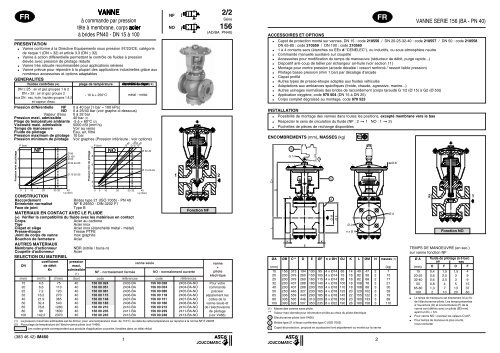
ENCOMBREMENTS (mm), MASSES (kg)<br />
L C **<br />
D<br />
G 1/4<br />
N<br />
3<br />
K K<br />
E<br />
ØA ØB C** D E ØF n x ØH ØJ K L ØM N masses (1)<br />
(mm) (kg)<br />
15 156 313 194 130 95 4 x Ø14 65 14 49 47 2 7<br />
20 200 379 260 150 105 4 x Ø14 75 16 82 58 2 15<br />
25 200 379 260 160 115 4 x Ø14 85 16 82 68 2 17<br />
32 200 407 288 180 140 4 x Ø18 100 18 108 78 2 21<br />
40 200 407 288 200 150 4 x Ø18 110 18 108 88 3 30<br />
50 250 446 327 230 165 4 x Ø18 125 20 129 102 3 39<br />
65 336 559 440 290 185 8 x Ø18 145 22 155 122 3 79<br />
80 336 565 446 310 200 8 x Ø18 160 23 160 133 3 89<br />
100 390 626 507 350 235 8 x Ø22 190 26 180 158 3 110<br />
(1) Masse des vannes sans pilote<br />
✶✶<br />
Valeur maxi donnée pour information et liée au choix du pilote électrique<br />
3 Electrovanne-pilote (voir V466)<br />
4 Brides type 21 à faces surélevées type C (ISO 7005)<br />
5<br />
Capot de protection, proposé en accessoire livré séparément ou monté sur la vanne<br />
5<br />
4<br />
Ø M<br />
Ø F<br />
Ø J<br />
n x Ø H<br />
Ø A<br />
Ø B<br />
;;;;; ;;; ;;;;<br />
;;;;; ;;;; ;;;;; ;;;; ;;;<br />
;;;; ;; ;; ;;;<br />
;;;;;<br />
;; ;;<br />
;;;<br />
;;;;<br />
;;;; ;;;;; ;;; ;;;; ;;;<br />
;;;<br />
;;;;; ;;;<br />
;; ;;<br />
;; ;; ;;<br />
;;;<br />
;;;;;<br />
;; ;;; ;;<br />
;;;<br />
;;; ;;;;;<br />
;; ; ;;; ;;;;;<br />
;; ; ;;;<br />
;; ;; ;<br />
;; ;;<br />
;;;; 2;;; ;; ;;<br />
;; ; ;;;<br />
;; ;<br />
;; ;<br />
;;;; ;;;<br />
;;;; ;;;<br />
;;;; ;;;;; ;;;<br />
Fonction NO<br />
TEMPS DE MANOEUVRE (en sec.)<br />
sur vanne fonction NF<br />
Ø A fluide de pilotage (à 6 bar)<br />
air eau<br />
(mm) O F O F<br />
15 0,4 1,5 1,5 4<br />
20-25 0,6 2,5 3 9<br />
32-40 0,6 2,5 3 9<br />
50 0,8 4 5 15<br />
65-80 1,3 7 13 37<br />
100 2 10 20 60<br />
● Le temps de manoeuvre est directement lié au Kv<br />
de l'électrovanne-pilote. Les temps présentés<br />
à l'ouverture (O) et à la fermeture (F) de la<br />
vanne sont définis avec un pilote (Ø3 mm)<br />
ayant un Kv = 3,5.<br />
● Pour vanne NO : inverser les valeurs O et F.<br />
● Pour temps de manoeuvre plus courts,<br />
nous consulter<br />
1
VANNE<br />
VANNE<br />
2 3/2<br />
FR FR<br />
PRESENTATION<br />
à commande par pression<br />
tête à membrane, corps acier<br />
acier<br />
à brides PN40 - DN 15 à 100<br />
● Vanne conforme à la Directive Equipements sous pression 97/23/CE, catégorie<br />
de risque 1 (DN > 32) et article 3.3 (DN ≤ 32)<br />
● Vanne à action différentielle permettant le contrôle de fluides à pression<br />
élevée avec pression de pilotage réduite<br />
● Vanne très robuste recommandée pour applications sévères<br />
● Vanne prévue pour répondre à la plupart des applications industrielles grâce aux<br />
nombreux accessoires et options adaptables<br />
GENERALITES<br />
fluides contrôlés (✷)<br />
plage de température étanchéité étanchéité étanchéité du du clapet clapet (✷)<br />
Pression différentielle<br />
vapeur d'eau<br />
eau surchauffée<br />
Pression maximum admissible<br />
Plage de température ambiante<br />
Viscosité maximum admissible<br />
0 à 25/40 bar (voir ci-dessous) [1 bar = 100 kPa]<br />
0 à 25/32 bar<br />
0 à 25/40 bar<br />
40 bar (1)<br />
- 5°C à + 60°C (2)<br />
5000 cSt (mm2 DN ≤ 25 : air et gaz groupes 1 & 2<br />
DN > 25 : air et gaz groupe 2<br />
tous DN : eau, huile, liquides groupes 1 & 2<br />
et vapeur d'eau<br />
- 10 à +250°C<br />
métal - métal<br />
Temps de manoeuvre<br />
Fluide de pilotage<br />
Pression maximum de pilotage<br />
Pression minimum de pilotage<br />
/s)<br />
Voir au verso<br />
Eau, air, filtré<br />
10 bar<br />
Voir graphe<br />
Pression mini de pilotage<br />
P (bar)<br />
10<br />
NO<br />
Ø 80<br />
Ø 100<br />
Ø 50<br />
Ø 65<br />
DN<br />
coefficient de débit<br />
Kv<br />
pression<br />
maximum<br />
admissible<br />
(3)<br />
(m références<br />
15 4,5 75 6 100 40 161 00 009 2603-BA-D2<br />
20 6,6 110 8,7 145 40 161 00 018 2604-BA-D2<br />
25 7,2 120 9,6 160 40 161 00 027 2605-BA-D2<br />
32 14,4 240 19,2 320 40 161 00 035 2606-BA-D2<br />
40 15,6 260 21 350 40 161 00 043 2607-BA-D2<br />
50 32,4 540 43,8 730 40 161 00 053 2608-BA-D2<br />
65 76,8 1280 103,8 1730 40 161 00 064 2610-BA-D2<br />
80 96 1600 129,6 2160 40 161 00 070 2611-BA-D2<br />
100 142,2 2370 192 3200 40 161 00 073 2613-BA-D2<br />
3 vanne seule<br />
NO - normalement ouverte<br />
/h) (l/min) (m (bar)<br />
codes<br />
3 CONSTRUCTION<br />
8<br />
6<br />
4<br />
2<br />
1<br />
0 5 10 20 3032<br />
Ø 15-20-25<br />
40<br />
∆p (bar)<br />
;;;;<br />
;;;;<br />
;;;; ;;;;; ;; ;<br />
;; ; ;;; ;;; ; ;; ;;; ;;; ;<br />
;;;;; ;;; ;;;<br />
;;; ;;;<br />
;;<br />
;<br />
;; ;<br />
;;;;; ;;;; ;;<br />
;;<br />
;;;;; ;;;;<br />
;;;;; ;;;;<br />
;;;;<br />
;;;;<br />
;;;;<br />
Raccordement<br />
Entrebride normalisé<br />
Brides type 21 (ISO 7005) - PN 40<br />
NF E 29350 - DIN 3202 F1<br />
Face de joint Type B<br />
MATERIAUX EN CONTACT AVEC LE FLUIDE<br />
(✷) Vérifier la compatibilité du fluide avec les matériaux en contact<br />
Corps<br />
Tige<br />
Clapet et siège<br />
Presse-étoupe<br />
Joint de corps de vanne<br />
Acier au carbone<br />
Acier inox<br />
Acier inox (étanchéité métal - métal)<br />
Tresse PTFE<br />
Inox graphite<br />
3ème voie rapportée<br />
AUTRES MATERIAUX<br />
Acier<br />
Membrane d'actionneur<br />
Coupelle d'actionneur<br />
SELECTION DU MATERIEL<br />
NBR (nitrile / buna-n)<br />
Acier<br />
2 1 3 2<br />
/h) (l/min)<br />
Ø 32-40<br />
3<br />
NO<br />
1 3<br />
Série<br />
161<br />
(AD/BA PN40)<br />
;;;;;<br />
;;;;;;;;;;;;;;;;;<br />
;;;;;<br />
;;;;;;;;;;;;;;;;;<br />
;;;;;;;;;;;;;;;;;<br />
;;;; ;;;;;;; ;;;;<br />
;;;; ;;;;;;; ;;;;<br />
;; ;;<br />
;;;;;;;<br />
;; ;;<br />
;;;;<br />
;;;;;<br />
;;;;;<br />
;;;;;;;<br />
;;;;<br />
;;;;;<br />
;;;;; ;;;;<br />
;;;;<br />
;;;;;;;<br />
;;; ;;<br />
;;; ;;<br />
;;;;;;;<br />
;; ;;; ;;<br />
;;;;<br />
;; ;;;; ;;<br />
;;;; ;;;;;;;<br />
;;;;<br />
;;;;<br />
;;;;<br />
;;;; ;;;;;;; ;;;;<br />
;;;;;;;<br />
;;;;<br />
;;;;<br />
1 ;;;; 2<br />
;;;;<br />
;;<br />
;;;; ;;;<br />
;;<br />
;;<br />
;;;; ;;;<br />
;;;; ;;;<br />
;;;<br />
;;;<br />
;;;<br />
3<br />
Fonction NO<br />
(1) La pression maximale admissible est de 40 bar, pour une température maxi. de 110°C. Au delà de cette température se reporter à la norme NF E 29005<br />
(2) Pour plage de température de l'électrovanne pilote (voir V466).<br />
vanne<br />
+<br />
pilote<br />
électrique<br />
Pour votre<br />
commande<br />
préciser<br />
séparement les<br />
codes de la<br />
vanne seule et<br />
de l'électrovanne<br />
de pilotage<br />
(voir V466-section 4)<br />
ACCESSOIRES ET OPTIONS<br />
4<br />
VANNE SERIE 161 (BA - PN40)<br />
● Capot de protection monté sur vannes, DN 15 : code 210556 / DN 20-25-32-40 : code 210557 / DN 50 : code 210558<br />
DN 65-80 : code 210559 / DN 100 : code 210560<br />
● 1 à 4 contacts secs (étanches ou EEx d "CENELEC"), ou inductifs, ou sous atmosphère neutre<br />
● Commande manuelle auxiliaire sur coupelle<br />
● Accessoires pour modification du temps de manoeuvre (réducteur de débit, purge rapide...)<br />
● Dispositif anti-coup de bélier par échangeur air-huile (voir section 11)<br />
● Montage pour contre pression (arcade décalée / ressort renforcé / ressort faible pression)<br />
● Clapet profilé<br />
● Autres types de presse-étoupe adaptés aux fluides véhiculés<br />
● Adaptations aux ambiances spécifiques (froide, chaude, agressive, marine...)<br />
● Autres usinages normalisés des brides de raccordement (corps taraudé G 1/2 (Ø15) à G2 (Ø 50), etc . . .)<br />
● Application oxygène, code 970 504 (DN 15 à DN 25)<br />
● Corps complet dégraissé au montage, code 970 523<br />
INSTALLATION<br />
● Possibilité de montage des vannes dans toutes les positions, excepté membrane vers le bas<br />
● Pochettes de pièces de rechange disponibles<br />
ENCOMBREMENTS (mm), MASSES (kg)<br />
C **<br />
L<br />
D<br />
3<br />
G 1/4<br />
K<br />
N<br />
ØM<br />
Ø F<br />
E<br />
K<br />
N<br />
1 2<br />
3<br />
N<br />
4<br />
Ø M<br />
Ø F<br />
K<br />
5<br />
Ø J<br />
n x Ø H<br />
Ø J<br />
n x Ø H<br />
ØA masse (1)<br />
ØB C** D E ØF n x ØH ØJ K L ØM N<br />
(mm) (kg)<br />
15 156 313 194 130 95 4 x Ø14 65 16 91 47 2 14<br />
20 200 379 260 150 105 4 x Ø14 75 18 128 58 2 16<br />
25 200 379 260 160 115 4 x Ø14 85 18 134 68 2 19<br />
32 200 407 288 180 140 4 x Ø18 100 20 152 78 2 23<br />
40 200 407 288 200 150 4 x Ø18 110 21 170 88 3 34<br />
50 250 446 327 230 165 4 x Ø18 125 23 185 102 3 45<br />
65 336 559 440 290 185 8 x Ø18 145 25 216 122 3 85<br />
80 336 565 446 310 200 8 x Ø18 160 26 225 138 3 100<br />
100 390 626 507 350 235 8 x Ø22 190 29 255 162 3 120<br />
(1) Masse des vannes sans pilote<br />
✶✶<br />
Valeur maxi donnée pour information et liée au choix du pilote électrique<br />
3 Electrovanne-pilote (voir V466)<br />
4 Brides type21 à faces surélevées type C (ISO 7005)<br />
5<br />
Capot de protection, proposé en accessoire livré séparément ou monté sur la vanne<br />
Ø B<br />
Ø A<br />
Ø A<br />
TEMPS DE MANOEUVRE (en sec.)<br />
Ø A fluide de pilotage (à 6 bar)<br />
air eau<br />
(mm) F O F O<br />
15 0,4 1,5 1,5 4<br />
20-25 0,6 2,5 3 9<br />
32-40 0,6 2,5 3 9<br />
50 0,8 4 5 15<br />
65-80 1,3 7 13 37<br />
100 2 10 20 60<br />
● Le temps de manoeuvre est directement lié au Kv<br />
de l'électrovanne-pilote. Les temps présentés<br />
à la fermeture (F) et à l'ouverture (O) de la<br />
vanne sont définis avec un pilote (Ø3 mm<br />
ayant un Kv = 3,5.<br />
● Pour temps de manoeuvre plus courts,<br />
nous consulter
1<br />
VALVES<br />
VALVES<br />
NC<br />
2/2<br />
GB 2<br />
GB<br />
FEATURES<br />
pressure-operated<br />
diaphragm-type operator, steel steel body<br />
with flanges, PN40 - DN 15 to 100<br />
● Valves satisfy the Pressure Equipment Directive 97/23/EC, category 1<br />
(DN > 32) or article 3.3 (DN ≤ 32)<br />
● Differential action valves for high-pressure fluid control at reduced piloting pressure<br />
● Heavy-duty valve recommended for demanding applications<br />
● With several accessories and options available, this valve can handle the majority<br />
of industrial applications<br />
GENERAL<br />
fluids (✷)<br />
DN ≤ 25: air and gas group 1 & 2<br />
DN > 25: air and gas group 2<br />
All DN: water, oil, liquids group 1 & 2<br />
and steam<br />
5<br />
metal-to-metal<br />
Differential pressure NC 0 to 40 bar [1 bar = 100 kPa]<br />
NO 0 to 25/40 bar (see graph below)<br />
Steam 0 to 32 bar<br />
Maximum allowable pressure 40 bar (1)<br />
Ambient temperature range - 5°C to + 60°C (2)<br />
Maximum viscosity 5000 cSt (mm 2 /s)<br />
Cycle time See overleaf<br />
Pilot fluids Water, air, filtered<br />
Max. pilot pressure 10 bar<br />
Min. pilot pressure See graphs (lower pressure: see options)<br />
Minimum pilot pressure<br />
8<br />
6<br />
4<br />
2<br />
P (bar)<br />
NC<br />
Ø 80<br />
Ø 100<br />
Ø 50<br />
Ø 32-40-65<br />
1<br />
0 5 10 20 30 32 40<br />
p (bar)<br />
SPECIFICATIONS<br />
Ø 15-20-25<br />
temperature range<br />
- 10 to +250°C<br />
Minimum pilot pressure<br />
P (bar)<br />
10<br />
8<br />
6<br />
4<br />
2<br />
1<br />
0 5 10 20 30 32<br />
Ø 80<br />
Ø 100<br />
Ø 50<br />
Ø 65<br />
NO<br />
2<br />
1<br />
Series<br />
156<br />
(AD/BA PN40)<br />
1 2<br />
(m catalogue number references catalogue number references<br />
15 4,5 75 40 156 00 024 2403-BA 156 00 028 2403-BA-NO<br />
20 6,6 110 40 156 00 051 2404-BA 156 00 054 2404-BA-NO<br />
25 7,2 120 40 156 00 081 2405-BA 156 00 086 2405-BA-NO<br />
32 16,2 270 40 156 00 115 2406-BA 156 00 118 2406-BA-NO<br />
40 21,9 365 40 156 00 148 2407-BA 156 00 151 2407-BA-NO<br />
50 32,4 540 40 156 00 183 2408-BA 156 00 186 2408-BA-NO<br />
65 76,8 1280 40 156 00 210 2410-BA 156 00 212 2410-BA-NO<br />
80 96 1600 40 156 00 235 2411-BA 156 00 239 2411-BA-NO<br />
100 142,2 2370 40 156 00 245 2413-BA 156 00 248 2413-BA-NO<br />
3 DN<br />
flow<br />
coefficient<br />
maximum<br />
allowable<br />
valve only<br />
Kv pressure<br />
(1)<br />
NC - normally closed NO - normally open<br />
/h) (l/min) (bar)<br />
(1) The maximum allowable pressure is 40 bar, for a maximum temperature of 110°C. Above this temperature, refer to standard NF E 29005.<br />
(2) For solenoid pilot temperature ranges (see V466).<br />
NO<br />
disc tightness (✷)<br />
Ø 32-40<br />
Ø 15-20-25<br />
40<br />
p (bar)<br />
CONSTRUCTION<br />
Connection Flanges, type 21 (ISO 7005) - PN 40<br />
Face to face dimensions NF E 29350 - DIN 3202 F1<br />
Facing Type B<br />
MATERIALS IN CONTACT WITH FLUID<br />
(✷) Ensure that the compatibility of the fluids in contact with the materials is verified<br />
Body Carbon steel<br />
Stem Stainless steel<br />
Disc and seat PTFE<br />
Stuffing-box Braided PTFE<br />
Valve body seal Stainless steel graphite<br />
Plug body Steel<br />
OTHER MATERIALS<br />
Diaphragm (operator) NBR (nitrile / buna-n)<br />
Bonnet (operator) Steel<br />
The codes in the grey shaded areas correspond to commonly used products which can be supplied rapidly<br />
Function NC<br />
valve<br />
+<br />
electrical<br />
pilot<br />
When ordering,<br />
please specify<br />
catalogue<br />
numbers for the<br />
valve and<br />
solenoid valve<br />
pilot separately<br />
(see V466)<br />
ACCESSORIES AND OPTIONS<br />
● Guard mounted on valves, DN 15: catalogue number 210556 / DN 20-25-32-40: 210557 / DN 50: 210558<br />
DN 65-80: 210559 / DN 100: 210560<br />
● 1 to 4 contacts (watertight or EEx d CENELEC), or inductive contacts, or in neutral atmosphere<br />
● Manual override on the bonnet of the operator<br />
● Accessories for adjustable response time (flow control, quick exhaust etc.)<br />
● Anti-waterhammer device available with air-oil exchanger (see Section 11)<br />
● Provisions for backpressure applications possible merely by off-setting the yoke, and using a low-pressure spring<br />
● Low pressure control (min. 1 bar) by off-setting the yoke<br />
● Special shaped valve disc for low flow at opening and closing<br />
● Other types of stuffing-box are available depending on the nature of the fluid used<br />
● Modifications for special environment (cold, hot, hostile, marine, etc.)<br />
● Others standardized flange forms (tapped body G 1/2 (Ø15) to G2 (Ø 50), etc.)<br />
● Oxygen service, catalogue number 970 504 (DN 15 to DN 25)<br />
● Valve body degreased during assembly, catalogue number 970 523<br />
INSTALLATION<br />
● The valves can be mounted in any position, except diaphragm downwards<br />
● Respect the direction of fluid flow (NC: 2 ➞ 1 NO: 1 ➞ 2)<br />
● Spare parts kits are available<br />
DIMENSIONS (mm), WEIGHT (kg)<br />
L C **<br />
D<br />
3<br />
G 1/4<br />
N<br />
K K<br />
E<br />
ØA ØB C** D E ØF n x ØH ØJ K L ØM N weight (1)<br />
(mm) (kg)<br />
15 156 313 194 130 95 4 x Ø14 65 14 49 47 2 7<br />
20 200 379 260 150 105 4 x Ø14 75 16 82 58 2 15<br />
25 200 379 260 160 115 4 x Ø14 85 16 82 68 2 17<br />
32 200 407 288 180 140 4 x Ø18 100 18 108 78 2 21<br />
40 200 407 288 200 150 4 x Ø18 110 18 108 88 3 30<br />
50 250 446 327 230 165 4 x Ø18 125 20 129 102 3 39<br />
65 336 559 440 290 185 8 x Ø18 145 22 155 122 3 79<br />
80 336 565 446 310 200 8 x Ø18 160 23 160 133 3 89<br />
100 390 626 507 350 235 8 x Ø22 190 26 180 158 3 110<br />
(1) Weight of valve without pilot<br />
✶✶<br />
Maximum value given for reference and related to choice of electric pilot<br />
3 Solenoid valve pilot (see V466)<br />
4 Flanges type 21 with stepped faces type C (ISO 7005)<br />
5<br />
Guard proposed as accessory; supplied separately or mounted on the valve<br />
5<br />
4<br />
Ø M<br />
Ø F<br />
Ø J<br />
n x Ø H<br />
6<br />
Ø A<br />
Ø B<br />
VALVES SERIES 156 (BA - PN 40)<br />
;;;;; ;;; ;;;;<br />
;;;;; ;;;; ;;;;; ;;;; ;;;<br />
;;;; ;; ;; ;;;<br />
;;;;;<br />
;; ;;<br />
;;;<br />
;;;;<br />
;;;; ;;;;; ;;; ;;;; ;;;<br />
;;;<br />
;;;;; ;;;<br />
;; ;;<br />
;; ;; ;;<br />
;;;<br />
;;;;;<br />
;; ;;; ;;<br />
;;;<br />
;;; ;;;;;<br />
;; ; ;;; ;;;;;<br />
;; ; ;;;<br />
;; ;; ;<br />
;; ;;<br />
;;;; 2;;; ;; ;;<br />
;; ; ;;;<br />
;; ;<br />
;; ;<br />
;;;; ;;; ;;;<br />
;;;; ;;;<br />
;;;; ;;;;; ;;;<br />
Function NO<br />
RESPONSE TIMES (in sec.)<br />
for a value with function NC<br />
Ø A pilot fluid (at 6 bar)<br />
air water<br />
(mm) O C O C<br />
15 0,4 1,5 1,5 4<br />
20-25 0,6 2,5 3 9<br />
32-40 0,6 2,5 3 9<br />
50 0,8 4 5 15<br />
65-80 1,3 7 13 37<br />
100 2 10 20 60<br />
Response time is directly related to the Kv of the<br />
solenoid valve pilot. The time indicated at closing<br />
(C) and opening (O) of the valve is determined by<br />
a pilot (Ø3 mm) with a Kv of 3.5.<br />
For a NO valve, swap the values of O and C.<br />
Consult us for shorter cycle times.<br />
1
VALVES<br />
VALVES<br />
2 3/2<br />
GB GB<br />
FEATURES<br />
pressure-operated<br />
diaphragm-type operator, steel steel body<br />
with flanges PN40 - DN 15 to 100<br />
● Valves satisfy the Pressure Equipment Directive 97/23/EC, category 1<br />
(DN > 32) or article 3.3 (DN ≤ 32)<br />
● Differential-action valve for high-pressure fluid control at reduced pilot pressure<br />
● Heavy-duty valve recommended for demanding applications<br />
● with several accesories and options available, this valve can handle the majority<br />
of industrial applications<br />
GENERAL<br />
Differential pressure 0 to 25/40 bar (see graph below) [1 bar = 100 kPa]<br />
steam 0 to 25/32 bar<br />
superheated water 0 to 25/40 bar<br />
Maximum valve pressure 40 bar (1)<br />
Ambient temperature range - 5°C to + 60°C (2)<br />
Maximum viscosity 5000 cSt (mm2 fluids (✷)<br />
DN ≤ 25: air and gas group 1 & 2<br />
temperature range disc tightness (✷)<br />
DN > 25: air and gas group 2<br />
All DN: water, oil, liquids group 1 & 2<br />
and steam<br />
-10 to +250°C<br />
metal-to-metal<br />
/s)<br />
Response time See overleaf<br />
Pilot fluids Water, air, filtered<br />
Max. pilot pressure 10 bar<br />
Min. pilot pressure See graph<br />
Minimum pilot pressure<br />
P (bar)<br />
10<br />
8<br />
6<br />
4<br />
2<br />
NO<br />
Ø 80<br />
Ø 100<br />
Ø 50<br />
Ø 65<br />
DN<br />
flow coefficient<br />
Kv<br />
maximum<br />
allowable<br />
pressure<br />
(3)<br />
(m references<br />
15 4,5 75 6 100 40 161 00 009 2603-BA-D2<br />
20 6,6 110 8,7 145 40 161 00 018 2604-BA-D2<br />
25 7,2 120 9,6 160 40 161 00 027 2605-BA-D2<br />
32 14,4 240 19,2 320 40 161 00 035 2606-BA-D2<br />
40 15,6 260 21 350 40 161 00 043 2607-BA-D2<br />
50 32,4 540 43,8 730 40 161 00 053 2608-BA-D2<br />
65 76,8 1280 103,8 1730 40 161 00 064 2610-BA-D2<br />
80 96 1600 129,6 2160 40 161 00 070 2611-BA-D2<br />
100 142,2 2370 192 3200 40 161 00 073 2613-BA-D2<br />
3 valve only<br />
NO - normally open<br />
/h) (l/min) (m (bar) catalogue number<br />
3 OTHER MATERIALS<br />
Diaphragm (operator) NBR (nitrile / buna-n)<br />
Bonnet (operator)<br />
SPECIFICATIONS<br />
Steel<br />
2 1 3 2<br />
/h) (l/min)<br />
Ø 32-40<br />
1<br />
0 5 10 20 3032 40<br />
∆p (bar)<br />
Ø 15-20-25<br />
CONSTRUCTION<br />
Connection Flanges, type 21 (ISO 7005) - PN 40<br />
Face to face dimensions NF E 29350 - DIN 3202 F1<br />
Facing Type B<br />
MATERIALS IN CONTACT WITH FLUID<br />
(✷) Ensure that the compatibility of the fluids in contact with the materials is verified<br />
Body Carbon steel<br />
Stem Stainless steel<br />
Disc and seat PTFE<br />
Stuffing-box Braided PTFE<br />
Valve body seal Stainless steel graphite<br />
Third flange connection Steel<br />
(1) The safe valve static pressure is 40 bar, for a maximum temperature of 110°C. Above this temperature refer to standard NF E 29005.<br />
(2) For solenoid pilot temperature range (see V 466).<br />
7<br />
NO<br />
1 3<br />
Series<br />
161<br />
(AD/BA PN40)<br />
;;;;;<br />
;;;;;;;;;;;;;;;;;<br />
;;;;;<br />
;;;;;;;;;;;;;;;;;<br />
;;;;;;;;;;;;;;;;;<br />
;;;; ;;;;;;; ;;;;<br />
;;;; ;;;;;;; ;;;;<br />
;; ;;<br />
;;;;;;;<br />
;; ;;<br />
;;;;<br />
;;;;;<br />
;;;;;<br />
;;;;;;;<br />
;;;;<br />
;;;;;<br />
;;;;; ;;;;<br />
;;;;<br />
;;;;;;;<br />
;;; ;;<br />
;;; ;;<br />
;;;;;;;<br />
;; ;;; ;;<br />
;;;;<br />
;; ;;;; ;;<br />
;;;; ;;;;;;;<br />
;;;;<br />
;;;;<br />
;;;;<br />
;;;; ;;;;;;; ;;;;<br />
;;;;;;;<br />
;;;; ;;;;<br />
;;;; ;;;;<br />
1;;;; ;;;;; ;;;;<br />
;; ; 2<br />
;; ; ;;; ;;; ; ;; ;;; ;;; ;<br />
;;;;; ;;; ;;; ;;;;<br />
;;; ;;;<br />
;;<br />
;; ;<br />
;; ;<br />
;;;;; ;;;; ;; ;;;; ;;;<br />
;;<br />
;; ;;<br />
;;;;; ;;;; ;;;; ;;;<br />
;;;;; ;;;; ;;;; ;;;<br />
;;;; ;;;<br />
;;;; ;;;<br />
;;;; ;;;<br />
3<br />
Function NO<br />
valve<br />
+<br />
electrical<br />
pilot<br />
When ordering,<br />
please specify<br />
codes for the<br />
valve and<br />
solenoid valve<br />
pilot separately<br />
(see V466 -<br />
Section 4)<br />
ACCESSORIES AND OPTIONS<br />
8<br />
VALVE SERIES 161 (BA - PN40)<br />
● Guard mounted on valves, DN 15: catalogue number 210556 / DN 20-25-32-40: 210557 / DN 50: 210558<br />
DN 65-80: 210559 / DN 100: 210560<br />
● 1 to 4 contacts (watertight or EEx d "CENELEC"), inductive contacts, or in neutral atmosphere<br />
● Manual override on the bonnet of the operator<br />
● Accessories for adjustable response time (flow control, quick exhaust etc.)<br />
● Anti-waterhammer device available with air-oil exchanger (see Section 11)<br />
● Provisions for backpressure applications possible merely by off-setting the yoke, and using a low-pressure spring<br />
● Special shaped valve disc for low flow at opening and closing<br />
● Other types of stuffing-box are available depending on the nature of the fluid used<br />
● Modifications for special environment (cold, hot, aggressive, marine etc.)<br />
● Other standardized flange forms (threaded body G 1/2 (Ø15) to G2 (Ø 50) etc.)<br />
● Oxygen service, code 970 504 (DN 15 to DN 25)<br />
● Valve body degreased during assembly, code 970 523<br />
INSTALLATION<br />
● The valves can be mounted in any position, except with the operator downwards<br />
● Spare parts kits are available<br />
DIMENSIONS (mm), WEIGHT (kg)<br />
C **<br />
L<br />
D<br />
3<br />
G 1/4<br />
K<br />
N<br />
ØM<br />
Ø F<br />
E<br />
ØA weights (1)<br />
ØB C** D E ØF n x ØH ØJ K L ØM N<br />
(mm) (kg)<br />
15 156 313 194 130 95 4 x Ø14 65 16 91 47 2 14<br />
20 200 379 260 150 105 4 x Ø14 75 18 128 58 2 16<br />
25 200 379 260 160 115 4 x Ø14 85 18 134 68 2 19<br />
32 200 407 288 180 140 4 x Ø18 100 20 152 78 2 23<br />
40 200 407 288 200 150 4 x Ø18 110 21 170 88 3 34<br />
50 250 446 327 230 165 4 x Ø18 125 23 185 102 3 45<br />
65 336 559 440 290 185 8 x Ø18 145 25 216 122 3 85<br />
80 336 565 446 310 200 8 x Ø18 160 26 225 138 3 100<br />
100 390 626 507 350 235 8 x Ø22 190 29 255 162 3 120<br />
(1) Weight of valve without pilot<br />
K<br />
N<br />
1 2<br />
3<br />
N<br />
Ø M<br />
Ø F<br />
n x Ø H<br />
✶✶<br />
Maximum value given for reference and related to choice of electric pilot<br />
3 Solenoid valve pilot (see V466)<br />
4 Flanges type 21 with stepped faces type C (ISO 7005)<br />
5<br />
Guard proposed as accessory; supplied separately or mounted on the valve<br />
K<br />
5<br />
4<br />
Ø J<br />
Ø J<br />
n x Ø H<br />
Ø B<br />
Ø A<br />
Ø A<br />
RESPONSE TIMES (in sec.)<br />
Ø A pilot fluid (at 6 bar)<br />
air water<br />
(mm) C O C O<br />
15 0,4 1,5 1,5 4<br />
20-25 0,6 2,5 3 9<br />
32-40 0,6 2,5 3 9<br />
50 0,8 4 5 15<br />
65-80 1,3 7 13 37<br />
100 2 10 20 60<br />
Response time is directly related to the Kv of the<br />
solenoid valve pilot. Valve closing (C) and opening<br />
(O) times correspond to a pilot (Ø 3 mm) with a Kv<br />
of 3,5.<br />
Consult us for shorter response times.


