You also want an ePaper? Increase the reach of your titles
YUMPU automatically turns print PDFs into web optimized ePapers that Google loves.
<strong>IX</strong> <strong>AMPLIFIER</strong><br />
<strong>IX</strong>500.1<br />
<strong>IX</strong>1000.1<br />
English Version<br />
Versión Español<br />
Amplificador del la Serie <strong>IX</strong>.1<br />
Deutsche Version<br />
Stereoverstärker der <strong>IX</strong>.1-Serie<br />
Version Francaise<br />
Amplificateur de série <strong>IX</strong>.1<br />
LIVIN’ LOUD
Authorized KICKER Dealer:<br />
Purchase Date:<br />
Model Number:<br />
Serial Number:<br />
PERFORMANCE<br />
INSTALLATION<br />
2 <strong>IX</strong> <strong>AMPLIFIER</strong>S<br />
<strong>IX</strong>.1-SERIES <strong>AMPLIFIER</strong>S Owner’s Manual<br />
<strong>IX</strong>500.1 / <strong>IX</strong>1000.1<br />
Model: <strong>IX</strong>500.1 <strong>IX</strong>1000.1<br />
RMS Power<br />
@ 14.4V, 4Ω mono, 1% THD+N<br />
@ 14.4V, 2Ω mono, 1% THD+N<br />
275W x 1<br />
500W x 1<br />
550W x 1<br />
1000W x 1<br />
Length 9-3/8” (238mm)<br />
Height 2-3/16” (55mm)<br />
Width 7-7/8” (200mm)<br />
Frequency Response ± 1dB 25Hz–200Hz<br />
Signal-to-noise Ratio 95dB, A-weighted, re: rated power<br />
Input Sensitivity Low Level: 125mV–5V<br />
High Level: 250mV–10V<br />
Selectable Electronic Crossover Variable lo-pass 50–200Hz, 24dB/octave<br />
Bass Boost Variable 0–18dB @ 40Hz<br />
Subsonic Filter 24dB/octave, fi xed @ 25Hz<br />
Maximum Effi ciency (2Ω) >80%<br />
Pro Tip: To get the best performance from your new KICKER Amplifi er and extend the warranty by 1 year, use<br />
genuine KICKER accessories and wiring.<br />
Mounting: Choose a structurally sound location to mount your KICKER amplifi er. Make sure there are no items<br />
behind the area where the screws will be driven. Choose a location that allows at least 4” (10cm) of open<br />
ventilation for the amplifi er. If possible, mount the amplifi er in the climate-controlled passenger compartment.<br />
Drill four holes using a 7/64” (3mm) bit and use the supplied #8 screws to mount the amplifi er. Use the <strong>IX</strong>SM<br />
mounting bracket (sold separately) to stack <strong>IX</strong> amplifi ers of different sizes.
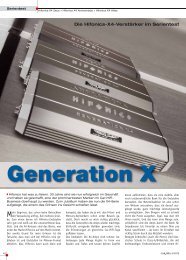
Wiring: Disconnect the vehicle’s battery to avoid an electrical short. Then, connect the ground wire to the<br />
amplifi er. Make the ground wire short, 24” (60cm) or less, and connect it to a paint-and-corrosion-free, solid,<br />
metal area of the vehicle’s chassis. Adding an additional ground wire of this same gauge (or larger) between the<br />
battery’s negative post and the vehicle chassis is recommended.<br />
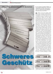
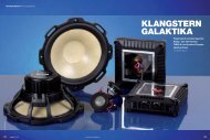
The <strong>IX</strong> amplifi er has dual input sensitivity differential RCA inputs which will receive either high or low level signals<br />
from your car stereo’s source unit. Ideally, when connecting the source unit to the amplifi er, the <strong>IX</strong> amplifi er’s input<br />
level switch should be set to “LO” and a low-level signal should run from the source unit’s stereo RCA output to<br />
the stereo RCA input on the end panel of the amplifi er using RCA interconnect cable. If a low-level stereo RCA<br />
output is not available on the source unit, the signal can be delivered to the amplifi er using the high-level speaker<br />
outputs on the source unit. Set the input level switch on the end panel of the amplifi er to “HI”. Crimp and solder<br />
RCA connectors to the end of the speaker wire running from the high-level speaker outputs on the source unit<br />
and connect the wire to the RCA Inputs on the end panel of the amplifi er or simplify the installation by using a<br />
KICKER ZISL as shown below. Either input method will provide a low-level output signal at the RCA output, which<br />
effectively passes the audio signal to another amplifi er or component. Keep the audio signal cable away from<br />
factory wiring harnesses and other power wiring. If you need to cross this wiring, cross it at a 90 degree angle.<br />
source unit<br />
high-level speaker<br />
outputs<br />
+<br />
–<br />
core conductor<br />
shield<br />
Model External Fuse<br />
(sold separately)<br />
<strong>IX</strong>SM<br />
sold separately<br />
to amplifi er<br />
KICKER ZISL<br />
OR to amplifi er<br />
source unit high-level<br />
speaker outputs<br />
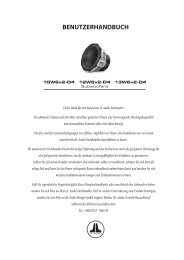
Install a fuse within 18” (45cm) of the battery and in-line with the power cable connected to your amplifi er. Install<br />
a second fuse within 18” (45cm) of the amplifi er. If you ever need to remove the amplifi er from the vehicle after it<br />
has been installed, the ground wire should be the last wire disconnected from the amplifi er--just the opposite as<br />
when you installed it.<br />
Power/Ground Wire KICKER Wiring Kit<br />
<strong>IX</strong>500.1 2 x 50 Ampere 4 Gauge PK4, CK4, ZCK4<br />
<strong>IX</strong>1000.1 2 x 100 Ampere 4 Gauge PK4, CK4, ZCK4<br />
3
SPEAKER<br />
AUTO<br />
POWER<br />
TURN ON<br />
+ –<br />
INPUT OUTPUT<br />
GND REM +12V<br />
12V DC AUDIO<br />
OFFSET<br />
L<br />
REMOTE BASS<br />
INPUT<br />
LEVEL<br />
R<br />
LO<br />
HI<br />
OPERATION<br />
24”<br />
(60cm)<br />
woofer<br />
bare-metal<br />
chassis ground<br />
SPEAKER<br />
AUTO<br />
POWER<br />
TURN ON<br />
+ –<br />
INPUT OUTPUT<br />
GND REM +12V<br />
12V DC AUDIO<br />
OFFSET<br />
INPUT<br />
LEVEL<br />
REMOTE BASS<br />
4 <strong>IX</strong> <strong>AMPLIFIER</strong>S<br />
LO<br />
HI<br />
external fuse<br />
remote turn-on<br />
(see page 5)<br />
L<br />
R<br />
external fuse<br />
MONO OPERATION<br />
minimum impedance of 2 ohms<br />
18”<br />
(45cm)<br />
Automatic Turn-On Selection: The <strong>IX</strong> series offers three different automatic turn-on modes that can be<br />
selected on the end panel; +12V, DC Offset, and Audio. Using either the DC Offset or Audio mode causes the<br />
REM terminal to have +12V out for turning on additional amplifi ers.<br />
• Remote Turn-On: Set the switch to +12V to use the remote turn-on lead from your source unit. Run 18<br />
gauge wire from the Remote Turn-On Lead on your source unit to the terminal labeled REM between the<br />
amplifi er’s positive and negative power terminals. This is the preferred automatic turn-on method.<br />
• DC Offset Turn-On: If Remote Turn-On is not an option, the next best setting is DC Offset. The DC Offset<br />
mode detects a 6V DC offset from the HI-Level speaker outputs when the source unit has been turned on.<br />
• Signal Sense Turn-On: The Audio setting is the fi nal alternative for Automatic turn-on. This is a Signal Sense<br />
turn-on method that detects the incoming audio signal from your source unit and automatically turns on the<br />
amp. This turn-on method will not work properly if the input gain control is not set appropriately.<br />
12V<br />
battery
Input Level: The RCA inputs on KICKER <strong>IX</strong> amplifi ers are capable of receiving either Hi or Low-level signals from<br />
your source unit. If the only output available from your source unit is a Hi-Level signal, simply press in the Input<br />
Level switch on the amplifi er. Refer to the wiring section of this manual for additional instructions.<br />
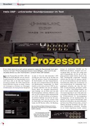
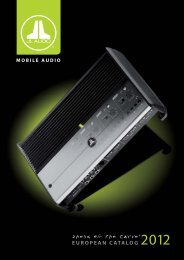
Remote Bass: With the KICKER ZXRC remote bass level control (sold separately), you have the ability to control<br />
the output level of the amplifi er remotely. To mount the ZXRC remote bass level control, simply screw the metal<br />
bracket to the chosen location, then slide the housing onto the bracket until it snaps into place. Run the cable<br />
from the controller to the “Remote Bass” jack on the amplifi er chassis.<br />
<strong>IX</strong><br />
PWR PRT<br />
ZXRC REMOTE BASS<br />
(sold separately)<br />
GAIN<br />
1. mount the<br />
metal bracket<br />
X-OVER FREQ<br />
0 11 50Hz 200Hz 0dB 18dB<br />
2. slide the housing until it snaps<br />
into the metal bracket<br />
SPEAKER<br />
AUTO<br />
POWER<br />
TURN ON<br />
+ –<br />
INPUT OUTPUT<br />
GND REM +12V<br />
12V DC AUDIO<br />
OFFSET<br />
INPUT<br />
LEVEL<br />
LO<br />
HI<br />
L<br />
R<br />
REMOTE BASS<br />
BASS BOOST<br />
Input Gain Control: The input gain control is not a volume control. It matches the output of the source unit to<br />
the input level of the amplifi er. Turn the source unit up to about 3/4 volume (if the source unit goes to 30, turn it<br />
to 25). Next, slowly turn (clockwise) the gain on the amplifi er up until you can hear audible distortion, then turn it<br />
down a little.<br />
Crossover Control: The variable crossover on the front of the amplifi er allows you to adjust the crossover<br />
frequency from 50–200Hz. The setting for this control is subjective; 80Hz is a good place to start.<br />
Bass Boost Control: The variable bass boost control on the front of the amplifi er is designed to give you<br />
increased output, 0–18dB, at 40 Hz. The setting for this control is subjective. If you turn it up, you must readjust<br />
the input gain control to avoid clipping the amplifi er.<br />
4-conductor phone cable<br />
back view<br />
5
TROUBLESHOOTING<br />
If your amplifi er does not appear to be working, check the obvious things fi rst such as blown fuses, poor or<br />
incorrect wiring connections, incorrect setting of crossover switch and gain controls, etc. There is an illuminated<br />
blue badge on top of the amplifi er denoting the power state of the amp in addition to the Protection LED on the<br />
end panel of your KICKER <strong>IX</strong> series amplifi er. When the blue badge is lit, this indicates the amplifi er is turned on<br />
and the amplifi er is functioning properly.<br />
BLUE Badge Light off, no output? With a Volt Ohm Meter (VOM) check the following: +12 volt power<br />
terminal (should read +12V to +16V) Remote turn-on terminal (should read +12V to +16V) Check for<br />
reversed power and ground connections. Ground terminal, for proper conductivity. Check for blown fuses.<br />
BLUE Badge Light on, no output? Check the following: RCA connections Test speaker outputs with a<br />
“known” good speaker. Substitute source unit with a “known” good source unit. Check for a signal in the<br />
RCA cable feeding the amplifi er with the VOM meter set to measure “AC” voltage.<br />
Protection LED fl ashing with loud music? The red LED indicates low battery voltage. Check all the<br />
connections in your vehicle’s charging system. It may be necessary to replace or charge your vehicle’s battery or<br />
replace your vehicle’s alternator.<br />
Protection LED on, no output? Amplifi er is very hot = thermal protection is engaged. Test for proper<br />
impedance at the speaker terminals with a VOM meter (see the diagrams in this manual for minimum<br />
recommended impedance and multiple speaker wiring suggestions). Also check for adequate airfl ow around<br />
the amplifi er. Amplifi er shuts down only while vehicle is running = voltage protection circuitry is engaged.<br />
Voltage to the amplifi er is not within the 10–16 volt operating range. Have the vehicle’s charging and electrical<br />
system inspected. Amplifi er will only play at low volume levels = short circuit protection is engaged. Check<br />
for speaker wires shorted to each other or to the vehicle chassis. Check for damaged speakers or speaker(s)<br />
operating below the minimum recommended impedance.<br />
No or low output? Check the balance control on source unit Check the RCA (or speaker input) and<br />
speaker output connections.<br />
Alternator noise-whining sound with engine’s RPM? Check for damaged RCA (or speaker input) cable<br />
Check the routing of RCA (or speaker input) cable Check the source unit for proper grounding Check<br />
the gain settings and turn them down if they are set too high.<br />
Reduced bass response? Reverse a speaker connection from positive to negative on the stereo/subwoofer<br />
channel(s); if the bass improves, the speaker was out of phase.<br />
Ground Noise? KICKER amplifi ers are engineered to be fully compatible with all manufacturers’ head units.<br />
Some head units may require additional grounding to prevent noise from entering the audio signal. If you are<br />
experiencing this problem with your head unit, in most cases running a ground wire from the RCA outputs on the<br />
head unit to the chassis will remedy this issue.<br />
Please Note: Modern high performance speakers have a lower DC Resistance than what used to be available.<br />
The KICKER Coaxial and Component speakers are rated at four ohms (some DC Resistances may be as low<br />
as 3 ohms) and work with any amplifi er designed to operate at a four ohm load. If you want to use two KICKER<br />
Coaxial or Component speakers on a single channel of your amplifi er, wire the speakers in series. This will<br />
improve the sound quality, lower the total harmonic distortion and lessen the thermal load at the amplifi er. This<br />
may prevent an amplifi er from shutting down due to over-current protection circuitry.<br />
CAUTION: When jump starting the vehicle, be sure that connections made with jumper cables are correct.<br />
Improper connections can result in blown amplifi er fuses as well as the failure of other critical systems in the<br />
vehicle.<br />
If you have more questions about the installation or operation of your new KICKER product, see the Authorized<br />
KICKER Dealer where you made your purchase. For more advice on installation, click on the SUPPORT tab on<br />
the KICKER homepage, www.kicker.com. Choose the TECHNICAL SUPPORT tab, choose the subject you are<br />
interested in, and then download or view the corresponding information. Please E-mail support@kicker.com or<br />
call Technical Services (405) 624-8583 for unanswered or specifi c questions.<br />
6 <strong>IX</strong> <strong>AMPLIFIER</strong>S
KICKER will now provide a threeyear<br />
warranty with all <strong>IX</strong>-Series<br />
Amplifi er purchases paired with a<br />
qualifying KICKER Installation Kit* .<br />
This extends the standard warranty by an additional<br />
year. Amplifi er and Kit must be purchased from an<br />
Authorized KICKER Dealer.<br />
KICKER amplifi er success is currently at an unheard-of rate, making the extended<br />
warranty program even more benefi cial to you.<br />
Using poor-quality, under-spec wiring kits will impede <strong>IX</strong> amplifi er performance.<br />
A superior-quality KICKER installation Kit is guaranteed to extend the life of <strong>IX</strong><br />
amplifi ers.<br />
The new extended warranty applies only to KICKER amplifi ers and accessories sold to consumers by Authorized<br />
KICKER Dealers in the United States of America or its possessions. It also only applies to the original purchaser of<br />
KICKER amplifi ers and accessories. One warranty extension per amplifi er is allowed regardless of the number of amplifi er<br />
installation kits purchased. This program does not apply to “B”-stock product or factory-refurbished product.<br />
This offer is for a limited time, so see your local Authorized KICKER Dealer soon for details.<br />
*U.S.A. Only | EE.UU. solamente | Nur USA | Les USA Seulement<br />
<strong>IX</strong>500.1<br />
275 x 1 @ 4 ohms, 14.4VDC, 1% THD, CEA-2006 (Watts)<br />
Signal to Noise Ratio -75dB CEA-2006 (ref: 1W, A-weighted)<br />
<strong>IX</strong>1000.1<br />
550 x 1 @ 4 ohms, 14.4VDC, 1% THD, CEA-2006 (Watts)<br />
Signal to Noise Ratio -75dB CEA-2006 (ref: 1W, A-weighted)<br />
7
Distribuidor autorizado de KICKER:<br />
Fecha de compra:<br />
Número de modelo del amplifi cador:<br />
Número de serie del amplifi cador:<br />
RENDIMIENTO<br />
Modelo: <strong>IX</strong>500.1 <strong>IX</strong>1000.1<br />
Potencia RMS<br />
@ 14.4V, 4Ω monofónico, 1% THD+N<br />
@ 14.4V, 2Ω monofónico, 1% THD+N<br />
275W x 1<br />
500W x 1<br />
8 AMPLIFICADOR <strong>IX</strong><br />
AMPLIFICADOR DE LA SERIE <strong>IX</strong>.1<br />
Manual del propietario<br />
550W x 1<br />
1000W x 1<br />
Largo 9-3/8” (238mm)<br />
Altura 2-3/16” (55mm)<br />
Ancho 7-7/8” (200mm)<br />
Respuesta de frecuencias ± 1dB 25Hz–200Hz<br />
Relación de señal a ruido 95dB, ponderado en A, ref: potencia nominal<br />
Sensibilidad de entrada Bajo Nivel: 125mV–5V<br />
Alto Nivel: 250mV–10V<br />
Crossover electrónico a selección Pasabajas variable de 50–200Hz, 24dB/octava<br />
Refuerzo de Bajos Variable 0–18dB @ 40Hz<br />
Filtro Subsónico 24dB/octava @ 25Hz<br />
Efi ciencia Máxima (2Ω) >80%<br />
INSTALACIÓN<br />
<strong>IX</strong>500.1 / <strong>IX</strong>1000.1<br />
Nota: Para obtener el mejor rendimiento de sus nuevos amplifi cadores KICKER, le recomendamos que use<br />
accesorios y cableado KICKER auténticos.<br />
Montaje: Escoja un lugar estructuralmente sólido para montar el amplifi cador KICKER. Asegúrese de que no<br />
haya nada por detrás de dónde van a entrar los tornillos. Escoja un lugar en que queden por lo menos 4 plg.<br />
(10 cm) de espacio abierto de ventilación alrededor del amplifi cador. Si es posible, monte el amplifi cador en el<br />
compartimiento de pasajeros, con ambiente acondicionado. Haga cuatro agujeros con una broca de 7/64 de<br />
plg. (3 mm) y monte el amplifi cador con los tornillos N° 8 que se suministran. Utilice el <strong>IX</strong>SM soporte de montaje<br />
(se vende por separado) a la pila <strong>IX</strong> amplifi cadores de diferentes tamaños.
Modelo Fusible<br />
Externo<br />
(no incluido)<br />
<strong>IX</strong>SM<br />
se vende por separado<br />
Cableado: Desconecte la batería del vehículo para evitar cortocircuitos. Luego, conecte un cable de conexión<br />
a tierra al amplifi cador. El cable de conexión a tierra debe ser corto, de 24 plg. (60 cm) o menos, y debe<br />
ir conectado a un punto sólido del chasis del vehículo en que no haya ni pintura ni corrosión. También se<br />
recomienda instalar un cable de conexión a tierra adicional, de este mismo calibre (o de mayor calibre), entre la<br />
terminal negativa de la batería y el chasis del auto.<br />
El amplifi cador <strong>IX</strong> tiene entradas RCA diferenciales de doble sensibilidad de entrada que reciben señales de alto<br />
nivel o bajo nivel de la unidad fuente del sistema estereofónico del automóvil. Idealmente, cuando se conecta<br />
la unidad fuente al amplifi cador, el selector de nivel de entrada del amplifi cador <strong>IX</strong> debe estar en la posición de<br />
bajo (LO) y una señal de bajo nivel debe ir de la salida RCA estereofónica de la unidad fuente a la entrada RCA<br />
estereofónica del panel de extremo del amplifi cador por un cable de interconexión RCA. Si no hay salida RCA<br />
estereofónica de bajo nivel en la unidad fuente, la señal se puede llevar al amplifi cador desde las salidas de<br />
altavoz de alto nivel de la unidad fuente. Fije el selector de nivel de entrada del panel de extremo del amplifi cador<br />
en la posición de alto (HI). Engarce y suelde conectores RCA al extremo del cable de altavoz procedente de<br />
las salidas de altavoz de alto nivel de la unidad fuente y conéctelo a las entradas RCA del panel de extremo del<br />
amplifi cador o simplifi car la instalación mediante un ZISL KICKER como se muestra a continuación. Cualquiera<br />
de los métodos de entrada permite establecer una señal de salida de bajo nivel en la salida RCA, lo cual, en<br />
efecto, pasa la señal de audio a otro amplifi cador o componente. Mantenga el cable de señal de audio alejado<br />
de los arneses de cableado de fábrica y otros cables de alimentación. Si es necesario cruzar este cableado,<br />
crúcelo en un ángulo de 90°.<br />
Cable de salida<br />
de altavoz de<br />
alto nivel<br />
+<br />
–<br />
cable central<br />
Conexión a tierra o blindaje<br />
Hacia el amplifi cador<br />
Cable de Alimentación y<br />
Conexión a Tierra<br />
Kit de cableado<br />
KICKER<br />
<strong>IX</strong>500.1 2 x 50A Calibre 4 PK4, CK4, ZCK4<br />
<strong>IX</strong>1000.1 2 x 100A Calibre 4 PK4, CK4, ZCK4<br />
Hacia el<br />
amplifi cador<br />
Instale un fusible a menos de 18 plg. (45 cm) de la batería y en línea con el cable de alimentación conectado<br />
al amplifi cador. Instalar un fusible segundo dentro de los 18 “(45cm) del amplifi cador. Si alguna vez necesita<br />
desmontar el amplifi cador, el cable de conexión a tierra debe ser el último que se desconecte del amplifi cador.<br />
Exactamente lo contrario de lo que se hace cuando se instala.<br />
O<br />
KICKER ZISL<br />
Cable de salida de<br />
altavoz de alto nivel<br />
9
SPEAKER<br />
AUTO<br />
POWER<br />
TURN ON<br />
+ –<br />
INPUT OUTPUT<br />
GND REM +12V<br />
12V DC AUDIO<br />
OFFSET<br />
L<br />
REMOTE BASS<br />
INPUT<br />
LEVEL<br />
R<br />
LO<br />
HI<br />
24”<br />
(60cm)<br />
woofer<br />
conexión a tierra<br />
FUNCIONAMIENTO<br />
INPUT<br />
LEVEL<br />
LO<br />
HI<br />
FUNCIONAMIENTO MONOFÓNICO<br />
impedancia mínima de 2 ohmios<br />
SPEAKER<br />
AUTO<br />
POWER<br />
TURN ON<br />
+ –<br />
INPUT OUTPUT<br />
GND REM +12V<br />
12V DC AUDIO<br />
OFFSET<br />
fusible externo<br />
encendido a distancia<br />
(página 11)<br />
REMOTE BASS<br />
Selección de Encendido Automático: La serie <strong>IX</strong> ofrece tres modalidades de encendido automático que se<br />
pueden seleccionar en el panel de extremo: +12V, compensación de CC y audio. Las modalidades de audio o<br />
compensación de CC dan +12V a la terminal REM para encender otros amplifi cadores.<br />
• Encendido a Distancia: Ponga el selector en +12V para usar el conductor de encendido a distancia de la<br />
unidad fuente. Instale cable calibre 18 desde el conductor de encendido a distancia de la unidad fuente<br />
hasta la terminal etiquetada REM entre las terminales de alimentación positiva y negativa del amplifi cador.<br />
Este es el método de encendido automático preferido.<br />
• Encendido por Compensación de CC: Si el encendido a distancia no es posible, la siguiente opción<br />
preferible es DC Offset. En la modalidad de compensación de CC, el amplifi cador detecta una subida de<br />
6V de las salidas de altavoz de alto nivel cuando la unidad fuente se ha encendido.<br />
• Encendido por Detección de Señal: La modalidad de es la opción fi nal de encendido automático. Este es<br />
un método de encendido en que el amplifi cador detecta la señal de audio procedente de la unidad fuente<br />
y se enciende automáticamente. Este método de encendido no funciona correctamente si el control de<br />
amplifi cación de entrada no se ha fi jado correctamente.<br />
10 AMPLIFICADOR <strong>IX</strong><br />
L<br />
R<br />
fusible externo<br />
18”<br />
(45cm)<br />
12V<br />
batería
Nivel de Entrada: Las entradas RCA de los amplifi cadores <strong>IX</strong> de KICKER aceptan señales de bajo nivel o alto<br />
nivel procedentes de la unidad fuente. Si la única salida disponible de la unidad fuente es una señal de alto nivel,<br />
oprima y deje adentro el selector de nivel de entrada del amplifi cador. En la sección de cableado de este manual<br />
hay más instrucciones.<br />
Control Remoto de Bajos-ZXRC: Con el control remoto de bajos (se vende por separado), el nivel de salida<br />
del amplifi cador se puede controlar a distancia. Para montar el control remoto de bajos, atornille el soporte<br />
de metal en el lugar escogido. Luego deslice el alojamiento sobre el soporte hasta que encaje en posición.<br />
Encamine el cable desde el control hasta el enchufe de control remoto de bajos (REMOTE BASS) del chasis del<br />
amplifi cador.<br />
<strong>IX</strong><br />
PWR PRT<br />
ZXRC CONTROL<br />
REMOTO DE BAJOS<br />
(se vende por<br />
separado)<br />
GAIN<br />
1. monte el<br />
soporte de<br />
metal<br />
X-OVER FREQ<br />
Control de Amplifi cación de Entrada: El control de amplifi cación de entrada no es un control de volumen.<br />
El control de amplifi cación de entrada hace que la salida de la fuente corresponda al nivel de entrada del<br />
amplifi cador. Suba el volumen de la unidad fuente a ¾ (si la unidad llega a 30, súbale el volumen a 25). A<br />
continuación, suba lentamente la amplifi cación (girando el control en el sentido de las manecillas del reloj) hasta<br />
que pueda oír distorsión, luego bájela un poquito.<br />
Control de Crossover: El crossover variable ubicado en la parte de arriba del amplifi cador le permite ajustar la<br />
frecuencia de crossover de 50 a 200 Hz. La confi guración de este control es subjetiva; 80 Hz es un buen punto<br />
de partida.<br />
Refuerzo de Bajos: El control variable de refuerzo de bajos ubicado en el panel de extremo del amplifi cador<br />
ha sido diseñado para dar una mayor salida de bajos, de 0 a 18 dB a 40 Hz. La confi guración de este control<br />
es subjetiva. Si usted lo sube, debe volver a ajustar el control de amplifi cación para evitar la limitación de la señal<br />
del amplifi cador.<br />
2. deslice el alojamiento hasta que<br />
encaje en el soporte de metal<br />
SPEAKER<br />
AUTO<br />
POWER<br />
TURN ON<br />
+ –<br />
INPUT OUTPUT<br />
GND REM +12V<br />
12V DC AUDIO<br />
OFFSET<br />
INPUT<br />
LEVEL<br />
LO<br />
HI<br />
L<br />
R<br />
REMOTE BASS<br />
BASS BOOST<br />
0 11 50Hz 200Hz 0dB 18dB<br />
vista desde atrás<br />
cable de teléfono de 4 conductores<br />
11
RESOLUCIÓN DE PROBLEMAS<br />
Si su amplifi cador parece no estar funcionando, revise lo obvio primero: fusibles quemados, conexiones malas<br />
o incorrectas, posición incorrecta de los selectores de crossover y amplifi cación, etc. Hay una insignia azul<br />
iluminada en la parte de arriba del amplifi cador de la serie <strong>IX</strong> de KICKER para indicar su estado de alimentación,<br />
además del indicador luminoso LED de protección ubicado en el panel de extremo. Cuando la insignia azul está<br />
encendida, el amplifi cador está encendido y funcionando correctamente.<br />
¿La luz de insignia AZUL está apagada y no hay salida? Con un voltímetro/ohmímetro (VOM), verifi que<br />
lo siguiente: Hay +12V en la terminal de alimentación (debe leerse entre +12V y +16V). Hay +12V en<br />
la terminal de encendido a distancia (debe leerse entre +12V y +16V). No hay conexiones invertidas de<br />
alimentación o conexión a tierra. La terminal de conexión a tierra tiene la conductividad adecuada. No hay<br />
fusibles quemados.<br />
¿La luz de insignia AZUL está encendida y no hay salida? Verifi que lo siguiente: Las conexiones RCA<br />
están bien. Las salidas de altavoces están bien pues han sido puestas a prueba con un altavoz en buenas<br />
condiciones. Se ha cambiado la unidad fuente por una unidad fuente en buenas condiciones. Con un<br />
medidor VOM confi gurado para medir voltaje de “CA”, se ha buscado una señal en el cable RCA que alimenta el<br />
amplifi cador.<br />
¿El indicador luminoso LED de “protection” destella con la música fuerte? El indicador luminoso<br />
LED rojo indica que hay bajo voltaje de batería. Revise todas las conexiones del sistema de carga eléctrica del<br />
vehículo. Puede ser necesario cambiar o cargar la batería del vehículo o cambiar el alternador del vehículo.<br />
¿El indicador luminoso LED de “protection” está encendido y no hay salida? El amplifi cador está<br />
muy caliente = Se ha activado el circuito de protección térmica. Con un medidor VOM, compruebe que las<br />
terminales de altavoz tengan la impedancia correcta (vea en este manual los diagramas que contienen datos de<br />
impedancia mínima recomendada y sugerencias de cableado de varios altavoces). Asegúrese también de que<br />
haya un fl ujo de aire adecuado alrededor del amplifi cador. El amplifi cador se apaga sólo cuando el vehículo<br />
está en marcha = Se ha activado el circuito de protección contra sobrevoltaje. El voltaje al amplifi cador no está<br />
dentro del intervalo de funcionamiento de 10V a 16V. Haga inspeccionar el sistema eléctrico y de carga eléctrica<br />
del automóvil. El amplifi cador sólo funciona a bajo volumen = Se ha activado el circuito de protección contra<br />
cortocircuitos. Asegúrese de que los cables de los altavoces no estén en cortocircuito entre sí o con el chasis<br />
del vehículo. Vea si hay altavoces dañados o funcionando a menos de la impedancia mínima recomendada.<br />
¿No hay salida de uno de los canales? Revise el control de balance de la unidad fuente. Revise las<br />
conexiones RCA (o de entrada de altavoz) y de salida de altavoz del canal.<br />
¿Hay ruido sibilante de alternador asociado a las RPM del motor? Vea si hay algún cable RCA (o de<br />
entrada de altavoz) dañado. Revise el encaminamiento del cable RCA (o de entrada de altavoz). Vea si la<br />
unidad fuente tiene conexión a tierra apropiada. Revise las confi guraciones de amplifi cación y bájelas si están<br />
muy altas.<br />
¿Hay baja respuesta de bajos? Invierta la conexión de uno de los altavoces de positiva a negativa en los<br />
canales estereofónicos y/o de subwoofer; si los bajos mejoran, el altavoz estaba fuera de fase.<br />
¿Hay ruido de conexión a tierra? Los amplifi cadores KICKER son totalmente compatibles con las unidades<br />
fuente de todos los fabricantes. Algunas unidades principales pueden necesitar más conexión a tierra para<br />
evitar que entre ruido a la señal de audio. En la mayoría de los casos, este problema con la unidad principal se<br />
resuelve instalando un cable de conexión a tierra desde las salidas RCA de la unidad principal al chasis.<br />
Nota importante: Los altavoces modernos de alto rendimiento tienen menos resistencia a la CC que los de<br />
antes. Los altavoces de componente o coaxiales de KICKER tienen un valor nominal de 4Ω (algunas resistencias<br />
de CC pueden llegar a 3Ω) y funcionan con cualquier unidad fuente o amplifi cador diseñado para funcionar<br />
con 4Ω de carga. Si desea utilizar dos altavoces de componente o coaxiales de KICKER en un solo canal de<br />
su amplifi cador, conéctelos en serie. Esto mejora la calidad del sonido, reduce la distorsión armónica total y<br />
disminuye la carga térmica en la unidad fuente o amplifi cador. Esto puede evitar que el amplifi cador se apague a<br />
causa del circuito de protección contra exceso de corriente.<br />
12 AMPLIFICADOR <strong>IX</strong>
PRECAUCIÓN: Cuando haga arrancar el vehículo con cables de arranque conectados a una batería externa,<br />
asegúrese de que las conexiones de los cables de arranque sean correctas. Conectar los cables de arranque<br />
de manera incorrecta puede quemar los fusibles del amplifi cador y causar fallas en otros sistemas del vehículo.<br />
Si tiene más preguntas sobre la instalación de su nuevo producto KICKER, vaya al distribuidor autorizado de<br />
KICKER donde lo compró. Si necesita más consejos sobre la instalación, haga clic en la lengüeta SUPPORT<br />
(apoyo) de la página Web de KICKER, www.kicker.com. Escoja la lengüeta TECHNICAL SUPPORT (apoyo<br />
técnico), escoja el tema que le interese y luego descargue o vea la información correspondiente. Envíe un<br />
mensaje por correo electrónico a support@kicker.com o comuníquese con Servicios Técnicos llamando al (405)<br />
624-8583 si tiene preguntas específi cas o a las cuales no haya encontrado respuesta.<br />
<strong>IX</strong>500.1<br />
275 x 1 @ 4 ohmios, 14.4VCC, 1% THD, CEA-2006 (W)<br />
Relación de Señal a Ruido -75dB CEA-2006 (ref: 1W, ponderado en A)<br />
<strong>IX</strong>1000.1<br />
550 x 1 @ 4 ohmios, 14.4VCC, 1% THD, CEA-2006 (W)<br />
Relación de Señal a Ruido -75dB CEA-2006 (ref: 1W, ponderado en A)<br />
13
Autorisierter KICKER-Händler:<br />
Kaufdatum:<br />
Verstärker-Modellnummer:<br />
Verstärker-Seriennummer:<br />
LEISTUNG<br />
Modell: <strong>IX</strong>500.1 <strong>IX</strong>1000.1<br />
RMS-Leistung<br />
@ 14.4V, 4Ω mono, 1% Gesamtklirrfaktor<br />
@ 14.4V, 2Ω mono, 1% Gesamtklirrfaktor<br />
275W x 1<br />
500W x 1<br />
14 <strong>IX</strong> VERSTÄRKER<br />
VERSTÄRKER DER <strong>IX</strong>.1 SERIE<br />
Benutzerhandbuch<br />
<strong>IX</strong>500.1 / <strong>IX</strong>1000.1<br />
550W x 1<br />
1000W x 1<br />
Länge 9-3/8” (238mm)<br />
Höhe 2-3/16” (55mm)<br />
Breite 7-7/8” (200mm)<br />
Frequenzgang ± 1dB 25Hz–200Hz<br />
Rauschabstand 95dB, A-gewichtet, re: Nennleistung<br />
Eingangsempfi ndlichkeit N-Pegel: 125mV–5V<br />
H-Pegel: 250mV–10V<br />
Wählbarer elektronischer Crossover Variabel tiefpass 50–200Hz, 24dB/oktave<br />
Bass-Boost Variabel 0–18dB @ 40Hz<br />
Subsonic-Filter 24dB/oktave @ 25Hz<br />
Max. Wirkungsgrad (2Ω) >80%<br />
Hinweis: Um das Maximum aus Ihrem neuen KICKER-Verstärker herauszuholen, sollten Sie echtes KICKER-<br />
Zubehör und KICKER-Kabel verwenden.<br />
INSTALLATION<br />
Befestigung: Wählen Sie für die Installation des KICKER-Verstärkers eine strukturell stabile Stelle. Vergewissern<br />
Sie sich, dass sich hinter der Einschraubposition der Schrauben nichts befi ndet. Wählen Sie eine Stelle, die<br />
mindestens 10 cm Lüftungsfreiraum für den Verstärker bietet. Installieren Sie, wenn möglich, den Verstärker im<br />
klimatisierten Fahrgastraum. Bohren Sie mit einem 3-mm-Bohrer vier Löcher und verwenden Sie die beiliegenden<br />
Nr. 8-Schrauben zur Befestigung des Verstärkers. Verwenden Sie die <strong>IX</strong>SM Montagehalterung (separat erhältlich)<br />
an <strong>IX</strong> Verstärker in verschiedenen Größen Stack.
Modell Externe Sicherung<br />
(nicht inbegriffen)<br />
<strong>IX</strong>SM<br />
separat erhältlich<br />
Anschluss: Trennen Sie den Anschluss der Fahrzeugbatterie, um einen Kurzschluss zu vermeiden. Schließen<br />
Sie dann das Massekabel an den Verstärker an. Verwenden Sie ein kurzes Erdungskabel (maximal 60 cm) und<br />
schließen Sie es an eine lack- oder korrosionsfreie Metallstelle an der Fahrzeugkarosserie an. Es wird auch<br />
empfohlen, ein weiteres Massekabel mit gleicher (oder größerer) Drahtstärke zwischen dem negativen Pol der<br />
Autobatterie und der Fahrzeugkarosserie zu verwenden.<br />
Der <strong>IX</strong>-Verstärker hat zwei RCA-Eingänge mit Eingangsempfi ndlichkeits-Differential, die entweder Hoch- oder<br />
Niedrigpegelsignale vom Autoradio empfangen. Am besten sollte beim Anschluss des Autoradios an den<br />
Verstärker der Eingangspegelschalter des <strong>IX</strong>-Verstärkers auf „LO“ stehen, und das Niedrigpegelsignal sollte über<br />
ein RCA-Verbindungskabel vom RCA-Ausgang des Autoradios zum Stereo-RCA-Eingang an der Endplatte des<br />
Verstärkers laufen. Wenn am Autoradio kein RCA-Niedrigpegelsignal-Ausgang vorhanden ist, kann das Signal<br />
mit den Hochpegel-Lautsprecherausgängen am Autoradio an den Verstärker übertragen werden. Stellen Sie den<br />
Eingangspegelschalter an der Endplatte des Verstärkers auf „HI“. Crimpen und löten Sie die RCA-Stecker an das<br />
Ende des Lautsprecherkabels von den Hochpegel-Lautsprecherausgängen am Autoradio und verbinden Sie<br />
das Kabel mit den RCA-Eingängen an der Endplatte des Verstärkers, oder Vereinfachung der Installation, indem<br />
Sie ein KICKER ZISL wie unten gezeigt. Beide Anschlussmethoden bieten ein N-Pegel-Ausgangssignal am<br />
RCA-Ausgang, der das Audiosignal effektiv an andere Verstärker oder Komponenten überträgt. Achten Sie beim<br />
Verlegen dieser Audiokabel darauf, dass sie Werks-Kabelbäume und andere Stromkabel nicht berühren. Wenn<br />
Sie die Kabel überkreuzen müssen, tun Sie dies in einem 90-Grad-Winkel.<br />
Hochpegel-<br />
Lautsprecherausgangskabel<br />
+<br />
–<br />
Kabelseele<br />
Erdung oder Abschirmung<br />
Zum Verstärker<br />
KICKER ZISL<br />
ODER Zum Verstärker<br />
Installieren Sie in maximal 45 cm Entfernung von der Batterie eine Sicherung in Reihe mit dem Stromkabel zum<br />
Verstärker. Installieren Sie in maximal 45 cm Entfernung von der Verstärker eine Sicherung in Reihe mit dem<br />
Stromkabel zum Verstärker. Wenn Sie je den Verstärker nach der Installation aus dem Fahrzeug ausbauen<br />
müssen, sollte die Masseleitung als letzte vom Verstärker getrennt werden, genau in der umgekehrten<br />
Reihenfolge wie bei der Installation.<br />
Massekabel KICKER Verkabelungssatz<br />
<strong>IX</strong>500.1 2 x 50 Ampere 4 GA PK4, CK4, ZCK4<br />
<strong>IX</strong>1000.1 2 x 100 Ampere 4 GA PK4, CK4, ZCK4<br />
Hochpegel-<br />
Lautsprecherausgangskabel<br />
15
SPEAKER<br />
AUTO<br />
POWER<br />
TURN ON<br />
+ –<br />
INPUT OUTPUT<br />
GND REM +12V<br />
12V DC AUDIO<br />
OFFSET<br />
L<br />
REMOTE BASS<br />
INPUT<br />
LEVEL<br />
R<br />
LO<br />
HI<br />
BETRIEB<br />
24”<br />
(60cm)<br />
Tieftöner<br />
SPEAKER<br />
AUTO<br />
POWER<br />
TURN ON<br />
+ –<br />
INPUT OUTPUT<br />
GND REM +12V<br />
12V DC AUDIO<br />
OFFSET<br />
INPUT<br />
LEVEL<br />
LO<br />
HI<br />
externe Sicherung<br />
Masse externe Sicherung<br />
Ferneinschaltung<br />
(Seite 17)<br />
MONO-BETRIEB<br />
Minimalimpedanz von 2 Ohm<br />
REMOTE BASS<br />
Automatische Einschaltung: Die <strong>IX</strong>-Serie bietet drei verschiedene automatische Einschaltmethoden, die<br />
an der Endplatte gewählt werden können: +12V, DC Offset und Audio. Wenn Sie „DC Offset“ oder „Audio“<br />
verwenden, wird am REM-Terminal +12V für das Einschalten weiterer Verstärker bereit gestellt.<br />
• Remote Turn-On (Ferneinschaltung): Stellen Sie den Schalter auf +12V, um das vom Autoradio kommende<br />
Ferneinschaltungskabel zu verwenden. Verlegen Sie 18 GA-Kabel von der Ferneinschaltung an Ihrem<br />
Autoradio zum REM-Terminal zwischen den positiven und negativen Stromanschlüssen des Verstärkers.<br />
Das ist die bevorzugte automatische Einschaltungsmethode.<br />
• DC Offset-Einschaltung: Wenn die Ferneinschaltung nicht möglich ist, wäre die nächstbeste Einstellung<br />
DC Offset. Der DC Offset-Modus entdeckt nach Einschalten des Autoradios einen 6-Volt-Anstieg an den<br />
Hochpegel-Lautsprecherausgängen.<br />
• Signal Sense-Einschaltung: Die Einstellung Audio ist die letzte Alternative für die automatische Einschaltung.<br />
Bei dieser Methode wird ein vom Autoradio eintreffendes Audiosignal entdeckt und der Verstärker dann<br />
automatisch eingeschaltet. Wenn der Eingangsverstärkungsregler nicht korrekt eingestellt ist, funktioniert<br />
diese Methode nicht richtig.<br />
16 <strong>IX</strong> VERSTÄRKER<br />
L<br />
R<br />
18”<br />
(45cm)<br />
12V<br />
Batterie
Eingangspegel: Die RCA-Eingänge an KICKER <strong>IX</strong>-Verstärkern können entweder Hoch- oder<br />
Niedrigpegelsignale vom Autoradio empfangen. Wenn nur ein H-Pegel-Signal vom Autoradio verfügbar ist,<br />
drücken Sie einfach den Schalter „Input Level“ am Verstärker. Weitere Hinweise fi nden Sie im Abschnitt<br />
„Anschluss“.<br />
Basspegel-Fernbedienung-ZXRC: Mit der Basspegel-Fernbedienung (separat erhältlich) können Sie<br />
den Ausgangspegel des Verstärkers per Fernbedienung kontrollieren. Um die Basspegel-Fernbedienung zu<br />
befestigen, schrauben Sie einfach die Metallhalterung am gewünschten Installationsort ein. Schieben Sie dann<br />
das Gehäuse in die Halterung, bis es einrastet. Stecken Sie das Kabel von der Fernbedienung in die „Remote<br />
Bass“-Buchse am Verstärkergehäuse.<br />
<strong>IX</strong><br />
PWR PRT<br />
ZXRC BASSPEGEL-<br />
FERNBEDIENUNG<br />
(separat erhältlich)<br />
GAIN<br />
1. Metallhalterung<br />
befestigen<br />
X-OVER FREQ<br />
0 11 50Hz 200Hz 0dB 18dB<br />
SPEAKER<br />
AUTO<br />
POWER<br />
TURN ON<br />
+ –<br />
INPUT OUTPUT<br />
GND REM +12V<br />
12V DC AUDIO<br />
OFFSET<br />
INPUT<br />
LEVEL<br />
LO<br />
HI<br />
2. Schieben Sie das Gehäuse<br />
ein, bis es in der Metallhalterung<br />
einrastet.<br />
L<br />
R<br />
REMOTE BASS<br />
BASS BOOST<br />
Eingangsverstärkungsregler: Der Eingangsverstärkungsregler ist kein Lautstärkeregler. Er passt den Ausgang<br />
des Autoradios an den Eingangspegel am Verstärker an. Stellen Sie das Autoradio auf etwa 3/4 der Lautstärke<br />
ein (wenn es also bis 30 geht, wählen Sie 25). Drehen Sie dann langsam den Verstärkungsregler am Verstärker<br />
(im Uhrzeigersinn), bis Sie eine hörbare Verzerrung feststellen. Drehen Sie ihn dann wieder etwas zurück.<br />
Crossover-Regler: Die variable Crossover-Einheit an der Oberseite des Verstärkers ermöglicht es Ihnen, die<br />
Crossover-Frequenz zwischen 50 und 200 Hz einzustellen. Die Einstellung für diesen Regler ist subjektiv, aber 80<br />
Hz wäre ein guter Ausgangspunkt.<br />
Bass-Boost-Regler: Der variable Bass-Boost-Regler an der Oberseite des Verstärkers ermöglicht einen<br />
verstärkten Bass von 0 – 18 dB bei 40 Hz. Die Einstellung dieses Reglers erfolgt nach subjektivem Geschmack.<br />
Wenn Sie ihn höher einstellen, müssen Sie zurückgehen und den Eingangsverstärkungsregler anpassen, um ein<br />
Clipping zu vermeiden.<br />
Vieradriges Telefonkabel<br />
Rückansicht<br />
17
PROBLEMBEHEBUNG<br />
Wenn der Verstärker nicht zu funktionieren scheint, sollten Sie zuerst offensichtliche Faktoren prüfen, wie<br />
durchgebrannte Sicherungen, schlechte oder fehlerhafte Verkabelung, inkorrekte Einstellung des Crossover-<br />
Schalters und der Verstärkungsregler etc. Oben am Verstärker befi ndet sich eine blau Leuchte für den<br />
Stromversorgungszustand des Verstärkers, und an der Endplatte Ihres Verstärkers der KICKER <strong>IX</strong>-Serie befi ndet<br />
sich eine Schutz-LED. Die blau Leuchte zeigt, dass der Verstärker eingeschaltet ist und richtig funktioniert.<br />
BLAU Leuchte aus, keine Ausgabe? Testen Sie mit einem Volt-Ohm-Messgerät (VOM) Folgendes: +12<br />
Volt Stromanschluss (Wert sollte +12V bis +16V sein) Ferneinschaltung (Wert sollte +12V bis +16V sein)<br />
Prüfen, ob Netz- und Masseanschlüsse falsch gepolt sind. Masseanschluss, auf korrekte Leitfähigkeit.<br />
Prüfen, ob Sicherungen durchgebrannt sind.<br />
BLAU Leuchte an, keine Ausgabe? Prüfen Sie Folgendes: RCA-Anschlüsse Lautsprecheranschlüsse<br />
mit „gutem“ Lautsprecher testen. Autoradio durch ein „gutes“ Autoradio ersetzen. Prüfen Sie mit dem<br />
VOM-Messgerät, das auf Wechselspannung eingestellt ist, die RCA-Zuleitung des Verstärkers auf ein Signal.<br />
Schutz-LED blinkt bei lauter Musik? Die rote LED zeigt eine niedrige Batteriespannung an. Prüfen Sie alle<br />
Verbindungen im Ladesystem Ihres Fahrzeugs. Sie müssen eventuell die Fahrzeugbatterie aufl aden oder ersetzen<br />
oder die Lichtmaschine auswechseln.<br />
Schutz-LED an, keine Ausgabe? Der Verstärker ist sehr heiß = Der Überhitzungsschutz ist aktiviert.<br />
Testen Sie den Widerstand an den Lautsprecheranschlüssen mit einem VOM-Messgerät (die Diagramme in<br />
dieser Anleitung zeigen die empfohlenen Mindestwiderstände und Vorschläge für den Anschluss mehrerer<br />
Lautsprecher). Prüfen Sie auch, ob der Verstärker ausreichende Lüftung hat. Der Verstärker schaltet sich<br />
nur während der Fahrt aus = Der Spannungsschutz ist aktiviert. Die Spannung am Verstärker liegt außerhalb<br />
des Betriebsbereichs von 10–16 Volt. Lassen Sie das Lade- und Elektriksystem des Fahrzeugs inspizieren.<br />
Der Verstärker erzeugt nur geringe Lautstärke = Die Kurzschluss-Sicherung ist aktiviert. Prüfen Sie, ob<br />
Lautsprecherkabel miteinander oder mit der Karosserie Kurzschlüsse erzeugen. Prüfen Sie, ob beschädigte oder<br />
unterhalb des Mindestwiderstands funktionierende Lautsprecher vorliegen.<br />
Keine Ausgabe aus einem Kanal? Prüfen Sie den Balanceregler am Autoradio. Prüfen Sie die RCA-<br />
oder Lautsprechereingangskabel und -ausgänge für den Kanal.<br />
Lichtmaschine erzeugt bei steigender Motordrehzahl heulendes Geräusch? Prüfen Sie, ob das<br />
RCA- oder Lautsprechereingangskabel defekt ist. Prüfen Sie den Verlauf des RCA- oder<br />
Lautsprechereingangskabels. Prüfen Sie, ob das Autoradio richtig geerdet ist. Prüfen Sie die<br />
Verstärkungseinstellungen und reduzieren Sie diese ggf.<br />
Verringerte Basswiedergabe? Wechseln Sie einen Lautsprecheranschluss an den Stereo-/Subwooferkanälen<br />
von Positiv zu Negativ; wenn der Bass nun besser klingt, war der Lautsprecher phasenverschoben.<br />
Störung durch Erdung? KICKER-Verstärker sind mit den Autoradios aller Hersteller kompatibel. Manche<br />
Autoradios erfordern eventuell weitere Erdung, um Störungen am Audiosignal zu verhindern.<br />
Wenn Sie Probleme mit dem Autoradio haben, reicht es meist, ein Massekabel von den RCA-Ausgängen am<br />
Autoradio zur Karosserie zu verlegen.<br />
Hinweis: Moderne Hochleistungslautsprecher haben einen geringeren Gleichstrom-Widerstand, als<br />
dies früher der Fall war. Die KICKER Koaxial- und Komponentenlautsprecher haben eine Impedanz von<br />
4 Ohm (manche Gleichspannungs-Widerstände können auch nur 3 Ohm betragen) und können mit<br />
jedem Verstärker zusammenarbeiten, der auf 4 Ohm ausgelegt ist. Wenn Sie zwei KICKER Koaxial- oder<br />
Komponentenlautsprecher an einem Kanal Ihres Lautsprechers verwenden wollen, müssen Sie diese in Reihe<br />
schalten. Dies verbessert die Soundqualität, verringert den Klirrfaktor und verringert die Wärmebelastung am<br />
Verstärker. Dies kann verhindern, dass sich der Verstärker aufgrund einer Überlastschaltung ausschaltet.<br />
18 <strong>IX</strong> VERSTÄRKER
ACHTUNG: Wenn Sie das Auto mit Starthilfekabel starten, müssen Sie sicherstellen, dass die Kabel korrekt<br />
angeschlossen sind. Falsche Anschlüsse können zu einem Durchbrennen der Verstärkersicherung und einem<br />
Ausfall anderer wichtiger Systeme im Fahrzeug führen.<br />
Wenn Sie weitere Fragen zur Installation oder zum Betrieb Ihres neuen KICKER-Produkts haben, setzen Sie<br />
sich bitte mit Ihrem autorisierten KICKER-Fachhändler in Verbindung. Weitere Installationshinweise fi nden Sie,<br />
indem Sie auf der KICKER-Startseite (www.kicker.com) auf die Registerkarte SUPPORT klicken. Wählen Sie<br />
das Register TECHNICAL SUPPORT und dann das gewünschte Thema, um die entsprechenden Informationen<br />
anzuzeigen oder herunterzuladen. Wenn Sie spezifi sche oder nicht beantwortete Fragen haben, erreichen Sie<br />
den Kundendienst unter support@kicker.com oder telefonisch unter +1 (405) 624-8583.<br />
<strong>IX</strong>500.1<br />
275 x 1 @ 4 ohms, 14.4V GS, 1% Klirrfaktor, CEA-2006 (Watts)<br />
Rauschabstand -75dB CEA-2006 (ref: 1W, A-gewichtet)<br />
<strong>IX</strong>1000.1<br />
550 x 1 @ 4 ohms, 14.4V GS, 1% Klirrfaktor, CEA-2006 (Watts)<br />
Rauschabstand -75dB CEA-2006 (ref: 1W, A-gewichtet)<br />
19
Revendeur agréé KICKER :<br />
Date d’achat :<br />
Numéro de modèle de l’amplifi cateur :<br />
Numéro de série de l’amplifi cateur :<br />
PERFORMANCES<br />
Modèle: <strong>IX</strong>500.1 <strong>IX</strong>1000.1<br />
Puissance Effi cace<br />
@ 14.4V, 4Ω mono, 1% THD+N<br />
@ 14.4V, 2Ω mono, 1% THD+N<br />
275W x 1<br />
500W x 1<br />
20 AMPLIFICATEUR <strong>IX</strong><br />
AMPLIFICATEUR SÉRIE <strong>IX</strong>.1 Manuel d’utilisation<br />
550W x 1<br />
1000W x 1<br />
Longueur 9-3/8” (238mm)<br />
Hauteur 2-3/16” (55mm)<br />
Largeur 7-7/8” (200mm)<br />
Réponse en Fréquence ± 1dB 25Hz–200Hz<br />
Rapport Signal sur Bruit 95dB, une puissance nominale<br />
Sensibilité d’Entrée Bas niveau: 125mV–5V<br />
Haut niveau: 250mV–10V<br />
Filtre Électronique Sélectionnable Passe-bas variable de 50–200Hz, 24dB/octave<br />
Amplifi cation des Graves Variable 0–18dB @ 40Hz<br />
Filtre Subsonique 24dB/octave @ 25Hz<br />
Effi cacité Maximale (2Ω) >80%<br />
INSTALLATION<br />
<strong>IX</strong>500.1 / <strong>IX</strong>1000.1<br />
Remarque : Pour optimiser les performances de votre nouvel amplifi cateur KICKER, il est conseillé d’utiliser des<br />
accessoires et des câbles KICKER d’origine.<br />
Montage: Choisissez un emplacement de structure saine pour monter votre amplifi cateur KICKER. Assurezvous<br />
que l’arrière de l’emplacement où vous allez enfoncer les vis ne comporte aucun élément. Choisissez un<br />
endroit assurant au moins 10 cm (4 po) de dégagement de ventilation ouverte pour l’amplifi cateur. Si possible,<br />
montez l’amplifi cateur dans l’habitacle passager climatisé. Percez quatre trous à l’aide d’un foret de 3 mm<br />
(7/64 po) et utilisez les vis nº 8 fournies pour monter l’amplifi cateur. Utilisez le <strong>IX</strong>SM support de montage (vendu<br />
séparément) pour pile <strong>IX</strong> amplifi cateurs de différentes tailles.
Modèle Fusible<br />
Externe<br />
(non inclus)<br />
<strong>IX</strong>SM<br />
vendu séparément<br />
Câblage: Débranchez la batterie du véhicule pour éviter un court-circuit. Ensuite, raccordez le fi l de masse à<br />
l’amplifi cateur. Le fi l de masse doit être le plus court possible, de 60 cm (24 po) maximum. Raccordez-le à une<br />
partie métallique solide du châssis du véhicule, ne comportant ni peinture ni rouille. Il est recommandé d’ajouter<br />
un fi l de masse supplémentaire de même calibre (ou de calibre supérieur) entre la borne négative de la batterie et<br />
le châssis du véhicule.<br />
L’amplifi cateur <strong>IX</strong> est doté de deux entrées RCA différentielles de sensibilité d’entrée qui reçoivent des signaux<br />
de haut ou bas niveau à partir de l’appareil source de la stéréo de votre voiture. Dans les conditions idéales,<br />
lors du raccordement de l’appareil source à l’amplifi cateur, le commutateur de niveau d’entrée de l’amplifi cateur<br />
<strong>IX</strong> doit être réglé à la position « LO » et un signal de bas niveau doit passer de la sortie RCA stéréo de l’appareil<br />
source à l’entrée RCA stéréo du panneau d’extrémité de l’amplifi cateur en utilisant le câble d’interconnexion RCA.<br />
Si aucune sortie RCA stéréo de bas niveau n’est disponible sur l’appareil source, le signal peut être transmis à<br />
l’amplifi cateur en utilisant les sorties de haut-parleur de haut niveau sur l’appareil source. Réglez le commutateur<br />
de niveau d’entrée sur le panneau d’extrémité de l’amplifi cateur à la position « HI ». Sertissez et soudez les<br />
connecteurs RCA à l’extrémité du fi l du haut-parleur venant des sorties de haut-parleur de haut niveau sur<br />
l’appareil source et raccordez le fi l aux entrées RCA sur le panneau d’extrémité de l’amplifi cateur, ou de simplifi er<br />
l’installation avec une ZISL KICKER, comme indiqué ci-dessous. Chacune de ces méthodes d’entrée envoie<br />
un signal de sortie de bas niveau à la sortie RCA qui transmet effi cacement le signal audio vers un autre<br />
amplifi cateur ou composant. Acheminez le câble du signal audio à l’écart des harnais de câblage d’usine et des<br />
autres câblages électriques. Si vous devez éventuellement croiser ces fi ls, procédez à angle droit.<br />
Fil de sortie de<br />
haut-parleur de<br />
haut niveau<br />
+ –<br />
Âme<br />
Masse ou blindage<br />
Vers l’amplifi cateur<br />
Fil de Masse /<br />
Alimentation<br />
KICKER ZISL<br />
OU Vers l’amplifi cateur<br />
KICKER Kit de câblage<br />
<strong>IX</strong>500.1 2 x 50 Ampères Calibre 4 PK4, CK4, ZCK4<br />
<strong>IX</strong>1000.1 2 x 100 Ampères Calibre 4 PK4, CK4, ZCK4<br />
Fil de sortie de haut-parleur<br />
de haut niveau<br />
Installez un fusible dans un rayon de 45 cm (18 po) de la batterie directement sur le câble d’alimentation<br />
raccordé à votre amplifi cateur. Installez un fusible seconde dans les 18 “(45cm) de l’amplifi cateur. Si vous devez<br />
retirer l’amplifi cateur après l’avoir installé dans le véhicule, débranchez toujours le fi l de masse en dernier, en<br />
procédant à l’opposé de l’installation.<br />
21
SPEAKER<br />
AUTO<br />
POWER<br />
TURN ON<br />
+ –<br />
INPUT OUTPUT<br />
GND REM +12V<br />
12V DC AUDIO<br />
OFFSET<br />
L<br />
REMOTE BASS<br />
INPUT<br />
LEVEL<br />
R<br />
LO<br />
HI<br />
UTILISATION<br />
24”<br />
(60cm)<br />
woofer<br />
INPUT<br />
LEVEL<br />
LO<br />
HI<br />
FONCTIONNEMENT MONO<br />
impédance minimum de 2 ohms<br />
SPEAKER<br />
AUTO<br />
POWER<br />
TURN ON<br />
+ –<br />
INPUT OUTPUT<br />
GND REM +12V<br />
12V DC AUDIO<br />
OFFSET<br />
Fusible Externe<br />
Masse Fusible Externe<br />
Mise sous tension à distance<br />
(page 23)<br />
REMOTE BASS<br />
Sélection de Mise sous Tension Automatique : La série <strong>IX</strong> est dotée de trois modes différents de mise<br />
sous tension automatique pouvant être sélectionnés au panneau d’extrémité de l’amplifi cateur : +12V, DC Offset<br />
(décalage c.c.) et Audio. L’utilisation du mode DC Offset ou Audio permet à la borne REM d’avoir une sortie de<br />
+12 V pour des amplifi cateurs supplémentaires.<br />
• Mise sous Tension à Distance : Réglez le commutateur sur +12V afi n d’utiliser le fi l de mise sous tension<br />
à distance à partir de votre appareil source. Faites passer un fi l de calibre 18 à partir du fi l de mise sous<br />
tension à distance sur votre appareil source jusqu’à la borne étiquetée REM entre la borne négative et<br />
la borne positive d’alimentation de l’amplifi cateur. Il s’agit de la méthode préférée de mise sous tension<br />
automatique.<br />
• Mise sous Tension en Mode DC Offset : Si l’option de mise sous tension précédente n’est pas possible, le<br />
meilleur réglage est DC Offset. Le mode DC Offset détecte une surtension de 6 volts en provenance des<br />
sorties de haut-parleur de niveau haut (HI) quand l’appareil source a été mis en marche.<br />
• Activation de la Détection du Signal : Le paramètre Audio est la troisième solution pour la mise sous tension<br />
automatique. Cette méthode est basée sur la détection du signal audio entrant à partir de l’appareil source,<br />
permettant la mise sous tension automatique de l’amplifi cateur. Cette activation ne fonctionne correctement<br />
que si la commande du gain d’entrée est correctement réglée.<br />
22 AMPLIFICATEUR <strong>IX</strong><br />
L<br />
R<br />
18”<br />
(45cm)<br />
12V<br />
Batterie
Niveau d’Entrée : Les entrées RCA sur les amplifi cateurs KICKER <strong>IX</strong> acceptent les signaux de niveaux haut et<br />
bas à partir de votre appareil source. Si votre appareil source n’est doté que d’une sortie de signal haut niveau,<br />
appuyez simplement sur le commutateur de niveau d’entrée sur l’amplifi cateur. Voir la section sur le câblage de<br />
ce manuel pour d’autres instructions.<br />
Télécommande du Niveau des Graves-ZXRC : La télécommande du niveau des graves ( vendu<br />
séparément ) permet de contrôler à distance le niveau de sortie de l’amplifi cateur. Pour monter la télécommande<br />
du niveau des graves, il suffi t de visser le support métallique à l’emplacement choisi. Ensuite, faites glisser le<br />
logement sur le support jusqu’à ce qu’il s’enclenche en place. Faites passer le câble du contrôleur à la prise de<br />
la télécommande des graves (« Remote Bass ») sur le châssis de l’amplifi cateur.<br />
<strong>IX</strong><br />
PWR PRT<br />
ZXRC TÉLÉCOMMANDE<br />
DU NIVEAU DES GRAVES<br />
(vendu séparément)<br />
GAIN<br />
1. montez le<br />
support métallique<br />
X-OVER FREQ<br />
Commande du Gain d’Entrée : La commande du gain d’entrée n’est pas une commande de volume. Elle fait<br />
correspondre la sortie de l’appareil source au niveau d’entrée de l’amplifi cateur. Réglez l’appareil source à environ<br />
¾ du volume (si le réglage de l’appareil source va jusqu’à 30, réglez à 25). Ensuite, augmentez lentement le<br />
gain de l’amplifi cateur en faisant tourner le bouton (dans le sens des aiguilles d’une montre) jusqu’à produire une<br />
distorsion audible, puis baissez un peu le gain.<br />
Commande de Filtre: Située sur le haut de l’amplifi cateur, la commande de fi ltre variable permet de régler la<br />
fréquence du fi ltre de 50 à 200 Hz. Le réglage de cette commande est subjectif. 80 Hz constitue un bon réglage<br />
de départ.<br />
Commande de l’Augmentation des Graves: Située sur le haut de l’amplifi cateur, la commande de<br />
l’augmentation des graves variable permet d’augmenter la sortie de 0 à 18 dB à 40 Hz. Le réglage de cette<br />
commande est subjectif. Si vous l’utilisez, vous devez revenir à la commande de gain d’entrée et la régler pour<br />
éviter la distorsion par écrêtage du signal de l’amplifi cateur.<br />
2. faites glisser le logement jusqu’à<br />
ce qu’il s’enclenche dans le support<br />
métallique<br />
SPEAKER<br />
AUTO<br />
POWER<br />
TURN ON<br />
+ –<br />
INPUT OUTPUT<br />
GND REM +12V<br />
12V DC AUDIO<br />
OFFSET<br />
INPUT<br />
LEVEL<br />
LO<br />
HI<br />
L<br />
R<br />
REMOTE BASS<br />
BASS BOOST<br />
0 11 50Hz 200Hz 0dB 18dB<br />
Vue arrière<br />
câble téléphonique à 4 conducteurs<br />
23
EN CAS DE DIFFICULTÉ<br />
Si votre amplifi cateur ne marche pas, vérifi ez d’abord les possibilités évidentes comme les fusibles sautés, les<br />
branchements incorrects ou desserrés, le mauvais réglage des commandes de gain et du commutateur du fi ltre,<br />
etc. En plus de la DEL de protection située sur le panneau d’extrémité de votre amplifi cateur KICKER série <strong>IX</strong>, un<br />
témoin bleu éclairé sur le dessus de l’amplifi cateur indique la mise sous tension de l’amplifi cateur. Le témoin bleu<br />
éclairé indique la mise sous tension et le bon fonctionnement de l’amplifi cateur.<br />
Témoin BLEU éteint, aucune sortie ? En utilisant un volt/ohmmètre (VOM), vérifi ez les points suivants :<br />
Borne d’alimentation +12 volts (entre +12 V et +16 V) Borne de mise sous tension à distance (entre +12 V<br />
et +16 V) Vérifi ez que les branchements d’alimentation et de masse ne sont pas inversés. La conductivité<br />
de la borne de masse. L’état des fusibles (aucun fusible sauté).<br />
Témoin BLEU allumé, aucune sortie ? Vérifi ez les points suivants : Branchements RCA Testez<br />
les sorties de haut-parleur en utilisant un haut-parleur dont vous vous êtes assuré du bon fonctionnement.<br />
Remplacez l’appareil source par un appareil dont vous vous êtes assuré du bon fonctionnement. Vérifi ez le<br />
passage du signal dans le câble RCA alimentant l’amplifi cateur en utilisant le volt/ohmmètre réglé pour mesurer la<br />
tension « c.a. ».<br />
DEL du « protection » clignotante lorsque le volume de la musique est élevé ? La DEL rouge indique<br />
une tension faible de la batterie. Vérifi ez tous les branchements du système de charge de votre véhicule. Le<br />
remplacement ou la recharge de la batterie (ou encore le remplacement de l’alternateur) de votre véhicule peut<br />
s’avérer nécessaire.<br />
DEL du « protection » allumée, aucune sortie ? L’amplifi cateur est très chaud = La protection thermique<br />
est engagée. Testez l’impédance aux bornes des haut-parleurs en utilisant un volt/ohmmètre (voir les schémas<br />
de ce manuel pour des recommandations sur l’impédance minimum et diverses suggestions de câblage<br />
pour les haut-parleurs). Vérifi ez également qu’il existe une circulation d’air adéquate autour de l’amplifi cateur.<br />
L’amplifi cateur ne s’arrête que lorsque le véhicule est en marche = La protection de tension est engagée. La<br />
tension à l’amplifi cateur ne se situe pas dans la plage de fonctionnement comprise entre 10 et 16 volts. Faites<br />
vérifi er le système de recharge et le système électrique du véhicule. L’amplifi cateur ne marche qu’à un niveau<br />
sonore faible = La protection anti-court-circuit est engagée. Vérifi ez que les fi ls des haut-parleurs ne sont pas en<br />
court-circuit entre eux ou avec le châssis du véhicule. Vérifi ez l’état des haut-parleurs ou l’impédance qui ne doit<br />
pas tomber en dessous du seuil minimum recommandé.<br />
Aucune sortie d’un canal ? Vérifi ez le contrôle de la balance sur l’appareil source Vérifi ez les<br />
branchements RCA (ou d’entrée de haut-parleur) et les branchements de sortie de haut-parleur pour le canal.<br />
Piaulement prolongé de l’alternateur avec le régime du moteur ? Vérifi ez l’état du câble RCA (ou<br />
d’entrée de haut-parleur) Vérifi ez l’acheminement du câble RCA (ou d’entrée de haut-parleur) Vérifi ez que<br />
l’appareil source est correctement mis à la masse Vérifi ez les paramètres de gain et baissez-en la valeur s’ils<br />
sont trop élevés.<br />
Réponse réduite des graves ? Inversez le branchement d’un haut-parleur de positif à négatif sur le ou les<br />
canaux de la stéréo/du caisson des graves. L’amélioration des graves indique que le haut-parleur était déphasé.<br />
Bruit de fond ? Les amplifi cateurs KICKER ont été étudiés pour être entièrement compatibles avec les unités<br />
de tête de tous les fabricants. Certaines unités de tête peuvent exiger une mise à la masse supplémentaire pour<br />
éviter toute interférence avec le signal audio. Pour remédier à ce problème éventuel, il suffi t dans la plupart des<br />
cas d’acheminer un fi l de masse à partir des sorties RCA sur l’unité de tête jusqu’au châssis.<br />
Remarque : La résistance c.c. des haut-parleurs modernes à hautes performances est inférieure à ce qui existait<br />
auparavant. Les haut-parleurs coaxiaux et des composants KICKER ont une résistance de 4 ohms (certaines<br />
résistances c.c. peuvent être aussi basses que 3 ohms) et peuvent fonctionner sur tout amplifi cateur conçu<br />
pour une charge de 4 ohms. Vous pouvez utiliser deux haut-parleurs coaxiaux ou de composants KICKER sur<br />
un seul canal de l’amplifi cateur en les raccordant en série. La qualité sonore est alors améliorée et la distorsion<br />
harmonique totale ainsi que la charge thermique au niveau de l’amplifi cateur sont réduites. Ceci peut empêcher<br />
l’arrêt d’un amplifi cateur provoqué par la circuiterie de protection de surintensité.<br />
24 AMPLIFICATEUR <strong>IX</strong>
ATTENTION : Lorsque vous effectuez une recharge rapide de la batterie du véhicule, assurez-vous que les<br />
branchements effectués avec les câbles de recharge rapide sont corrects. Des branchements incorrects<br />
peuvent faire sauter les fusibles de l’amplifi cateur et provoquer des pannes dans d’autres systèmes cruciaux du<br />
véhicule.<br />
Si vous avez d’autres questions relatives à l’installation ou au fonctionnement de votre nouveau produit KICKER,<br />
contactez le revendeur agréé KICKER qui vous l’a vendu. Pour obtenir d’autres conseils sur l’installation, cliquez<br />
sur l’onglet SUPPORT de la page d’accueil KICKER, www.kicker.com. Sélectionnez l’onglet TECHNICAL<br />
SUPPORT, choisissez le sujet qui vous intéresse et téléchargez ou affi chez les informations correspondantes.<br />
Si vous avez d’autres questions, envoyez un message électronique à support@kicker.com ou téléphonez aux<br />
services techniques en composant le (+1) 405-624-8583.<br />
<strong>IX</strong>500.1<br />
275 x 1 @ 4 ohms, 14.4V C.C., 1% de Distorsion Harmonique Totale, CEA-2006 (W)<br />
Rapport Signal sur Bruit -75dB CEA-2006 (ref: 1W, pondéré A)<br />
<strong>IX</strong>1000.1<br />
550 x 1 @ 4 ohms, 14.4V C.C., 1% de Distorsion Harmonique Totale, CEA-2006 (W)<br />
Rapport Signal sur Bruit -75dB CEA-2006 (ref: 1W, pondéré A)<br />
25
ELECTRONICS LIMITED WARRANTY<br />
KICKER warrants this product to be free from defects in material and workmanship under normal use for a period of<br />
THREE (3) MONTHS from date of original purchase with receipt. When purchased from an Authorized KICKER Dealer<br />
it is warranted for TWO (2) YEARS from date of original purchase with receipt. In all cases you must have the original<br />
receipt. Should service be necessary under this warranty for any reason due to manufacturing defect or malfunction<br />
during the warranty period, KICKER will repair or replace (at its discretion) the defective merchandise with equivalent<br />
merchandise at no charge. Warranty replacements may have cosmetic scratches and blemishes. Discontinued products<br />
may be replaced with more current equivalent products. This warranty is valid only for the original purchaser and is not<br />
extended to owners of the product subsequent to the original purchaser. Any applicable implied warranties are limited in<br />
duration to a period of the express warranty as provided herein beginning with the date of the original purchase at retail,<br />
and no warranties, whether express or implied, shall apply to this product thereafter. Some states do not allow limitations<br />
on implied warranties; therefore, these exclusions may not apply to you. This warranty gives you specifi c legal rights;<br />
however you may have other rights that vary from state to state.<br />
WHAT TO DO IF YOU NEED WARRANTY OR SERVICE:<br />
Defective merchandise should be returned to your local Authorized Stillwater Designs (KICKER) Dealer for warranty<br />
service. Assistance in locating an Authorized Dealer can be found at www.kicker.com or by contacting Stillwater Designs<br />
directly. You can confi rm that a dealer is authorized by asking to see a current authorized dealer window decal.<br />
If it becomes necessary for you to return defective merchandise directly to Stillwater Designs (KICKER), call the KICKER<br />
Customer Service Department at (405) 624-8510 for a Return Merchandise Authorization (RMA) number. Package only<br />
the defective items in a package that will prevent shipping damage, and return to:<br />
Stillwater Designs, 3100 North Husband St, Stillwater, OK 74075<br />
The RMA number must be clearly marked on the outside of the package. Please return only defective components. The<br />
return of functioning items increases your return freight charges. Non-defective items will be returned freightcollect to you.<br />
For example, if a subwoofer is defective, only return the defective subwoofer, not the entire enclosure. Include a copy<br />
of the original receipt with the purchase date clearly visible, and a “proof-of-purchase” statement listing the Customer’s<br />
name, Dealer’s name and invoice number, and product purchased. Warranty expiration on items without proof-ofpurchase<br />
will be determined from the type of sale and manufacturing date code. Freight must be prepaid; items sent<br />
freight-collect, or COD, will be refused.<br />
WHAT IS NOT COVERED?<br />
This warranty is valid only if the product is used for the purpose for which it was designed. It does not cover:<br />
o Damage due to improper installation<br />
o Subsequent damage to other components<br />
o Damage caused by exposure to moisture, excessive heat, chemical cleaners, and/or UV radiation<br />
o Damage through negligence, misuse, accident or abuse. Repeated returns for the same damage may be<br />
considered abuse<br />
o Any cost or expense related to the removal or reinstallation of product<br />
o Speakers damaged due to amplifi er clipping or distortion<br />
o Items previously repaired or modifi ed by any unauthorized repair facility<br />
o Return shipping on non-defective items<br />
o Products with tampered or missing barcode labels<br />
o Products returned without a Return Merchandise Authorization (RMA) number<br />
o Freight Damage<br />
o The cost of shipping product to KICKER<br />
o Service performed by anyone other than KICKER<br />
HOW LONG WILL IT TAKE?<br />
KICKER strives to maintain a goal of 48-hour service for all electronics (amplifi ers, crossovers, equalizers, etc.) returns.<br />
Delays may be incurred if lack of replacement inventory or parts is encountered. Failure to follow these steps may void<br />
your warranty. Any questions can be directed to the KICKER Customer Service Department at (405) 624-8510. Contact<br />
your International KICKER dealer or distributor concerning specifi c procedures for your country’s warranty policies.<br />
Note: All specifi cations and performance fi gures are subject to change. Please visit www.kicker.com for the most<br />
current information.<br />
P.O. Box 459 • Stillwater, Oklahoma 74076 • USA • (405) 624–8510<br />
26 <strong>IX</strong> <strong>AMPLIFIER</strong>S<br />
stillwaterdesigns<br />
10<strong>IX</strong>.1-C-20091112
INTERNATIONAL WARRANTY<br />
Contact your International KICKER dealer or distributor concerning specifi c procedures for your country’s warranty policies.<br />
WARNING: KICKER products are capable of producing sound levels that can permanently damage your hearing! Turning up a<br />
system to a level that has audible distortion is more damaging to your ears than listening to an undistorted system at the same<br />
volume level. The threshold of pain is always an indicator that the sound level is too loud and may permanently damage your<br />
hearing. Please use common sense when controlling volume.<br />
GARANTÍA INTERNACIONAL Versión Español<br />
Comuníquese con su concesionario o distribuidor KICKER internacional para obtener infor ación sobre procedimientos específi cos<br />
relacionados con las normas de garantía de su país.<br />
ADVERTENCIA: Los excitadores KICKER son capaces de producir niveles de sonido que pueden dañar permanentemente<br />
el oído. Subir el volumen del sistema hasta un nivel que produzca distorsión es más dañino para el oído que escuchar un<br />
sistema sin distorsión al mismo volumen. El dolor es siempre una indicación de que el sonido es muy fuerte y que puede dañar<br />
permanentemente el oído. Sea precavido cuando controle el volumen.<br />
La frase “combustible para vivir la vida Livin’ Loud a todo volumen” se refi ere al entusiasmo por la vida que la marca KICKER<br />
de estéreos de automóvil representa y a la recomendación a nuestros clientes de que vivan lo mejor posible (“a todo volumen”)<br />
en todo sentido. La línea de altavoces y amplifi cadores KICKER es la mejor del mercado de audio de automóviles y por lo tanto<br />
representa el “combustible” para vivir a todo volumen en el área de “estéreos de automóvil” de la vida de nuestros clientes.<br />
Recomendamos a todos nuestros clientes que obedezcan todas las reglas y reglamentos locales sobre ruido en cuanto a los<br />
niveles legales y apropiados de audición fuera del vehículo.<br />
INTERNATIONALE GARANTIE Deutsche Version<br />
Nehmen Sie mit Ihren internationalen KICKER-Fachhändler oder Vertrieb Kontakt auf, um Details über die Garantieleistungen in<br />
Ihrem Land zu erfahren.<br />
WARNUNG: KICKER-Treiber können einen Schallpegel erzeugen, der zu permanenten Gehörschäden führen kann! Wenn Sie ein<br />
System auf einen Pegel stellen, der hörbare Verzerrungen erzeugt, schadet das Ihren Ohren mehr, als ein nicht verzerrtes System<br />
auf dem gleichen Lautstärkepegel. Die Schmerzschwelle ist immer eine Anzeige dafür, dass der Schallpegel zu laut ist und zu<br />
permanenten Gehörschäden führen kann. Seien Sie bei der Lautstärkeeinstellung bitte vernünftig!<br />
Der Slogan “Treibstoff für Livin’ Loud” bezieht sich auf die mit den KICKER-Autostereosystemen assoziierte Lebensfreude und die<br />
Tatsache, dass wir unsere Kunden ermutigen, in allen Aspekten ihres Lebens nach dem Besten (“Livin’ Loud”) zu streben. Die<br />
Lautsprecher und Verstärker von KICKER sind auf dem Markt für Auto-Soundsysteme führend und stellen somit den “Treibstoff”<br />
für das Autostereoerlebnis unserer Kunden dar. Wir empfehlen allen unseren Kunden, sich bezüglich der zugelassenen und<br />
passenden Lautstärkepegel außerhalb des Autos an die örtlichen Lärmvorschriften zu halten.<br />
GARANTIE INTERNATIONALE Version Française<br />
Pour connaître les procédures propres à la politique de garantie de votre pays, contactez votre revendeur ou distributeur<br />
International KICKER.<br />
AVERTISSEMENT: Les haut-parleurs KICKER ont la capacité de produire des niveaux sonores pouvant endommager l’ouïe de<br />
façon irréversible ! L’augmentation du volume d’un système jusqu’à un niveau présentant une distorsion audible endommage<br />
davantage l’ouïe que l’écoute d’un système sans distorsion au même volume. Le seuil de la douleur est toujours le signe que le<br />
niveau sonore est trop élevé et risque d’endommager l’ouïe de façon irréversible. Réglez le volume en faisant prevue de bon sens!<br />
L’expression “ carburant pour vivre plein pot “ fait référence au dynamisme de la marque KICKER d’équipements audio pour<br />
véhicules et a pour but d’encourager nos clients à faire le maximum (“ vivre plein pot “) dans tous les aspects de leur vie. Les<br />
haut-parleurs et amplifi cateurs KICKER sont les meilleurs dans le domaine des équipements audio et représentent donc pour nos<br />
client le “ carburant pour vivre plein pot “ dans l’aspect “ installation audio de véhicule “ de leur vie. Nous encourageons tous nos<br />
clients à respecter toutes les lois et réglementations locales relatives aux niveaux sonores acceptables à l’extérieur des véhicules.<br />
P.O. Box 459 • Stillwater, Oklahoma 74076 • USA • (405) 624–8510<br />
27
©2009 Stillwater Designs