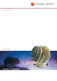
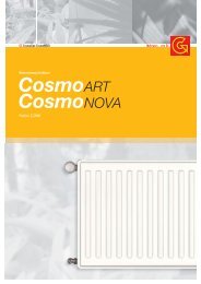
ca. 75 50 A B I ACHTUNG ! Heizkörperrückansicht ATTENTION ! Back of radiator 2 1 BL X 4 7 3 5 8 50 X/2 X/2 Abb. 2 6 A B I Entlüftung Ventilation Entlüftung B I BH min. 150 mm Y 126 Rücklauf Return pipe 64 - 76 38 - 50 50 Abb. 1 A B Abb. 3 BL X 500 400 600 495 750 645 BH Y 1220 1008 1766 1554 Vorlauf Flow pipe B I
INSTALLATION / MONTAGE <strong>FULDA</strong> D Die Installation und Inbetriebnahme Ihres Designheizkörpers <strong>FULDA</strong>-<strong>VM</strong> ist von einer zugelassenen Fachfirma durchzuführen. Bei der Installation sind die einschlägigen Normen bzw. die nationalen elektrotechnischen Sicherheitsvorschriften wie ÖVE- und VDE-Bestimmungen zu beachten. Unter Berücksichtigung der geometrischen Maße des Designheizkörpers <strong>FULDA</strong>-<strong>VM</strong> und der Anschlussarmatur ist die Verrohrung vorzubereiten (siehe Abb. 1 bzw. Abb 3). Wir empfehlen einen seitlichen Mindestabstand zum Heizkörper von 100 mm einzuhalten. Dabei ist Nachfolgendes zu berücksichtigen. Wird ein Elektroheizelement verwendet, kann dieses in eine der beiden 1/2" Muffen I eingedichtet werden. Dabei sind die Hinweise der Montageanleitung für das PTC-Elektroheizelement zu beachten. Vor der Wandmontage des Heizkörpers ist zu beachten (siehe Abb. 3): Der Vorlaufanschluss befindet sich links von der Mitte des Designheizkörpers. WANDMONTAGE: Aufstecken der beigepackten Blechmuttern 1 auf die Montagestutzen 2 (Abb. 2). Anreißen, bohren der Löcher Position A - Bohrer ø10 - und setzen der Dübel entsprechend den Aufhängungsmaßen - (Abb. 1). Für eine sehr solide Wandmontage wird empfohlen, auch die Wandfüße Position B an die Wand zu schrauben. Erfolgt dies nicht, dann dienen die Wandfüße Position B als Distanzierungen. Empfehlung: Messen Sie bitte vorher zur Heizkörperidentifizierung die Abstandsmaße der Montagestutzen 2 (Abb. 1 u. Abb. 2) nach. Nach Bedarf (Wandbeschaffenheit) sind die beigepackten Kunststoffbeilagen 3 auf die Wandfüße 4 zu kleben (Abb. 2). Bitte auf saubere Klebestellen achten. Befestigung der oberen und eventuell unteren Wandfüße 4 und diese waagrecht bzw. senkrecht ausrichten, wobei die Senklochbohrungen 5 in den Wandfüßen nach außen stehen müssen. Dabei sollen die Wandmontageschrauben 6 in der Mitte der Langlöcher der Wandfüße montiert werden. (Es wird empfohlen, die Abstandsmaße der montierten Wandfüße vor der Heizkörperwandmontage zu kontrollieren.) Falls die unteren Wandfüße B als Distanzierung verwendet werden, sind diese auf die Montagestutzen 2 zu stecken und mit den Blechschrauben 7 zu befestigen. Wandmontage des Heizkörpers, indem die oberen Montagestutzen 2 (eventuell auch unteren Montagestutzen) in die Wandfüße A - eventuell auch B gesteckt und mittels Blechschraube 7 miteinander verbunden werden. Durch das Langloch im Montagestutzen kann der Wandabstand variiert werden. Verstellmöglichkeiten in Baulängen- bzw. Bauhöhenrichtung sind durch das Langloch in der beweglichen Scheibe 8 im Wandfuß gegeben, sollten die hydraulischen Anschlüsse nicht genau passen. Für den hydraulischen Anschluss verwenden Sie bitte die beigepackte Anschlussarmatur und beachten Sie die entsprechende Montageanleitung. Die Designheizkörper <strong>FULDA</strong>-<strong>VM</strong> sind hochwertige Produkte, die nicht nur der Raumheizung dienen, sondern auch zur Trocknung von Handtüchern geeignet sind. Daher ist zu beachten, dass sie heiße Oberflächen besitzen. Es dürfen nur Textilien, die mit Wasser gewaschen wurden, getrocknet werden. Selbstverständlich ist es unzulässig, diesen Heizkörper als Kletteroder Sportgerät zu benutzen. Zur Reinigung der Heizkörperoberflächen sind schonende, nicht scheuernde Reinigungsmittel zu verwenden. (Vergoldete Oberflächen dürfen nur mit warmem Wasser und weichen Lappen gereinigt werden.) Für den Fall des Elektroheizungsbetriebes muss die Heizwasserausdehnung immer bis zum Expansionsgefäß gewährleistet sein, z. B. durch Öffnen des Rücklaufventiles. Um Wärmeverschleppungen in das Heizungsnetz zu vermeiden, wird in diesem Fall empfohlen, das Thermostatventil zu schließen. Selbstverständlich darf die Elektroheizung nur in Betrieb genommen werden, wenn der Heizkörper komplett mit Heizungswasser gefüllt ist. Wird der Heizkörper elektrisch betrieben, darf er aus sicherheitstechnischen Gründen nicht komplett abgedeckt werden. INSTALLATION / ASSEMBLY <strong>FULDA</strong>-<strong>VM</strong> BEDIENUNG UND PFLEGE D OPERATION AND CARE GB GB Your design radiator <strong>FULDA</strong>-<strong>VM</strong> must be installed and commissioned by an authorised company. All relevant installation standards and ÖVE and VDE regulations must be complied with. The applicable standards and national electrotechnical safety regulations such as the ÖVE and VDE regulations must be observed for installation. Prepare the pipework, taking into account the geometric dimensions of the design radiator <strong>FULDA</strong>-<strong>VM</strong> and the connector (see Abb. 1 and 3). We recommend keeping a minimum lateral clearance of 100 mm from the radiator, whereby the following should be noted. If an electrical heater cartridge is used it may be sealed in one of the two 1/2" sleeves l. It is important that the instructions contained in the PTC-Electrical heating assembly instructions are complied with. Before mounting the radiator on the wall, (see Abb. 3): Please note that the flow pipe fitting is to the left of the centre of the valve pipe. WALL INSTALLATION: Place the sheet metal screws 1 provided on the mounting connections 2 (Abb. 2). Mark and drill the holes position A - drill ø10 - and position the dowels according to the suspension dimensions - (Abb. 1). To ensure solid wall fitting for valve radiators we recommend that the wall feet B are screwed to the wall. If this is not done, the wall feet B act as spacers. Recommendation: First verify the distance between the mounting connections 2 (Abb. 1 and 2) in order to identify the radiator. If necessary, (wall condition) stick the transparent plastic shims 3 provided onto the wall feet 4 (Abb. 2). Please ensure that the adhesion surfaces are clean. Fix the upper and possibly lower wall feet 4 in a horizontal, respectively vertical position. The countersunk boreholes 5 in the wall feet must face outwards. The wall mounting screw 6 should be mounted in the middle of the oblong holes of the wall feet. (We recommend that you check the distance between the mounted wall feet before mounting the radiator on the wall.) If the lower wall feet B were used as spacers, screw them to the mounting connections 2 with sheet metal screw 7. Mount the radiator on the wall by putting the upper mounting connections 2 (and possibly the lower mounting connections) in the wall feet A - and possibly B and connect them with the sheet metal screw 7. The wall space can be varied by the oblong hole in the mounting connections. If the hydraulic fittings do not fit exactly, height and length can be adjusted by means of the oblong hole in the movable washer 8 in the wall feet. Use the enclosed connection fittings for the hydraulic connection and observe the corresponding instructions. <strong>FULDA</strong>-<strong>VM</strong> design radiators are high quality products which are suitable for drying towels as well as heating rooms. For this reason it is important to remember that they have hot surfaces. Only textiles that have been washed in water may be dried. Of course it is not permitted to use the radiators as climbing frames or sports equipment. The radiator surfaces must be cleaned with gentle non-scouring cleansing agents. (Gold-plated surfaces may only be cleaned with warm water and soft cloths.) For electrical heating operations the heating water must always be able to expand to the expansion tank, e.g. by opening the non-return valve. To prevent heat being transferred to the heating network in this case, we recommend closing the thermostat valve. Of course, the electrical heating may only be switched on after the radiator has been completely filled with water. For safety reasons, the radiator must not be covered completely if it is operated electrically.