Montageanleitung - ten Haaft GmbH
Montageanleitung - ten Haaft GmbH
Montageanleitung - ten Haaft GmbH

You also want an ePaper? Increase the reach of your titles
YUMPU automatically turns print PDFs into web optimized ePapers that Google loves.
<strong>Montageanleitung</strong><br />
Mounting Instruction / Notice de montage<br />
Innovative Mobile Technology<br />
Vision III<br />
01/2013 Sprache / language / langue: deutsch / englisch / français
Inhaltsverzeichnis<br />
Table of con<strong>ten</strong>t<br />
Manuel d’utilisation<br />
<strong>Montageanleitung</strong> 5<br />
Assembly Instructions<br />
Instructions de montage<br />
Lieferumfang 7<br />
Scope of delivery<br />
Con<strong>ten</strong>u de la fourniture<br />
Montagevorarbei<strong>ten</strong> 9<br />
Mounting preparation<br />
Mounting preparation<br />
Montageplatte montieren 14<br />
Mounting of the assembly plate<br />
Pose de la plaque de fixation<br />
System aufsetzen 16<br />
Locating the external unit<br />
Mise en place du système<br />
Spannungsversorgung 22<br />
Power supply<br />
Alimentation électrique<br />
Sicherheitsschaltung 28<br />
Protection circuit<br />
Circuit de sécurité<br />
Receiver-Anschluss 29<br />
Connecting the receiver<br />
Connexion du récepteur<br />
Bedienung der Anlage (Kurzanleitung) 30<br />
Operating the system (quick reference)<br />
Utilisation de système (instructions sommaires)<br />
Demontage der Anlage 32<br />
Removal of the system<br />
Démontage du système<br />
Erste Hilfe bei Störungen 33<br />
First help with malfunctions<br />
Premières mesures à prendre en cas d’anomalie<br />
Hinweise zum Umweltschutz 35<br />
Notes on the protection of the environment<br />
Consignes sur la protection de l´environnement
<strong>Montageanleitung</strong><br />
Assembly Instructions<br />
Instructions de montage<br />
Keine Angst, dieses mobile Satelli<strong>ten</strong>empfangssystem zu montieren ist kein Hexenwerk. Einige Punkte sind allerdings zu<br />
beach<strong>ten</strong>. Bitte folgen Sie daher genau dieser <strong>Montageanleitung</strong>, damit Ihre Anlage nachher auch zu Ihrer vollen Zufriedenheit<br />
arbeitet. Montage- und Bedienungsanleitungen können bei Bedarf auch über das<br />
Internet von www.<strong>ten</strong>-haaft.de herunter geladen werden.<br />
Lesen Sie jeden Punkt vorher einmal ganz durch, bevor Sie anfangen ihn auszuführen.<br />
Arbei<strong>ten</strong> Sie auf diese Weise Punkt für Punkt nacheinander durch.<br />
Achtung:<br />
Empfindliches Gerät. Nicht am Spiegelarm reißen. Spiegelarm nicht manuell heben oder drehen, Spiegelarm darf nur<br />
motorisch bewegt werden. Nur an Kunststoffabschirmung oder Aluplatte hochheben. Die Schrauben am Gehäuse dürfen<br />
nur vom Hersteller der Anlage gelöst werden.<br />
Vorsicht:<br />
Fassen Sie niemals in den Bereich der Außeneinheit während sich diese bewegt!<br />
Hinweis für den Betrieb auf Caravans/Wohnanhängern:<br />
Die 12V Bordnetzversorgung, die von standardmäßig in Caravans eingebau<strong>ten</strong> Spannungswandlern erzeugt wird, ist<br />
häufig nicht stabil genug für den Betrieb des Satelli<strong>ten</strong>systems. Wir empfehlen für den Einbau in Caravans den von uns<br />
zu beziehenden Zusatzwandler.<br />
Don’t worry – it does not require any witchcraft to assemble the mobile satellite system. Some points should be observed,<br />
however. Please accurately follow these assembly instructions so that afterwards your unit will operate to your full<br />
satisfaction. If necessary, mounting and operating instructions can also be downloaded over the internet from www.<br />
<strong>ten</strong>-haaft.de.<br />
Please completely read each point at least once before you begin to execute it.<br />
In this way, complete point for point successively.<br />
Note:<br />
This is a sensitive device. Do not tear at the dish arm. Do not manually lift or turn the dish arm; the dish arm may only be<br />
moved by the motor. Only raise at plastic screen or aluminium plate. The screws at the plastic housing may be loosened<br />
only<br />
by the manufacturer of the unit.<br />
Caution:<br />
Never grip into the range of the external unit while it is moving!<br />
Note for operation on caravans/trailers:<br />
The 12 V board system power supply which is generated by voltage transformers built into caravans as a standard is<br />
frequently not stable enough for the operation of the satellite system. We recommend the auxiliary transducer which can<br />
be ordered from us for installation into caravans.<br />
5
Ne vous inquiétez pas, le montage du système satellite mobile n’a rien de sorcier. Il convient toutefois d’observer quelques<br />
points. Suivez précisément les présentes instructions de montage pour garantir le bon fonctionnement ultérieur de<br />
votre système. Si besoin est, les instructions de montage et d’installation sont également disponibles sur le site www.<br />
<strong>ten</strong>-haaft.de.<br />
Lisez soigneusement et complètement chaque point des instructions de montage avant de commencer à l’exécuter.<br />
Procédez de cette manière point par point et dans l’ordre indiqué.<br />
At<strong>ten</strong>tion :<br />
Appareil sensible. Ne pas tirer sur le bras de l’an<strong>ten</strong>ne parabolique. Ne pas soulever ou tourner manuellement le bras de<br />
l’an<strong>ten</strong>ne parabolique, le bras ne doit être déplacé que par le moteur. Ne le soulever que par le capot en plastique ou la<br />
plaque en aluminium. Les vis sur le boîtier en plastique ne doivent être desserrées que par le fabricant du système.<br />
At<strong>ten</strong>tion :<br />
Ne rien saisir à proximité de l’unité extérieure lorsque celle-ci est en mouvement !<br />
Instructions pour l’utilisation sur les caravanes :<br />
L’alimentation de réseau de bord 12 V produite par les convertisseurs de <strong>ten</strong>sion montés d’origine dans les caravanes<br />
n‘est souvent pas assez stable pour le système satellite. Pour les caravanes, nous vous recommandons de poser le convertisseur<br />
auxiliaire figurant dans notre catalogue.<br />
6
Lieferumfang<br />
Scope of delivery<br />
Con<strong>ten</strong>u de la fourniture<br />
Das sollte jetzt vor Ihnen liegen:<br />
l Bedienteil<br />
l Steuerbox (versteckt einbaubar)<br />
l Außeneinheit<br />
l Spiegel (je nach Modell schon montiert)<br />
l Montageplatte (an der Außeneinheit montiert)<br />
l Schraubenpackung<br />
l Kabelsatz zur Außeneinheit (weißes Koaxkabel gemeinsam mit Steuerkabel in schwarzer Ummantelung,<br />
bei manchen Modellen schon montiert)<br />
l Koaxkabel zur Verbindung Ihres Sat- Empfängers mit der Steuerbox<br />
l Western Kabel (Verbindung zwischen Steuerbox und Bedienteil)<br />
l Stromversorgungskabel (Steuerbox)<br />
l Bedienungsanleitung<br />
l <strong>Montageanleitung</strong><br />
l Außerdem wird für den Fernsehempfang benötigt: Satelli<strong>ten</strong>-Receiver (nicht im Lieferumfang enthal<strong>ten</strong>)<br />
The following items should now be in front of you:<br />
l Operating device<br />
l Control unit<br />
l External unit<br />
l Dish<br />
l Mounting plate<br />
l Screw package<br />
l Cable set to the external unit (white coax cable together with control cable in black sheath)<br />
l Coax cable for connection of your satellite receiver with the control unit<br />
l Western cable (connection between control unit and Operating device)<br />
l Power cable (control unit)<br />
l Operating instructions<br />
l Assembly instructions<br />
l In addition required for television reception: Satellite receiver (not comprised in the scope of delivery)<br />
Vous devriez avoir devant vous :<br />
l Boîtier de commande<br />
l Appareil de commande<br />
l Unité extérieure<br />
l An<strong>ten</strong>ne parabolique<br />
l Plaque de fixation<br />
l Jeu de vis<br />
l Faisceau de câblage allant à l’unité extérieure (câble coaxial blanc et câble de commande dans une gaine noire)<br />
l Câble coaxial pour relier votre récepteur satellite à l‘appareil de commande<br />
l Câble Western (liaison appareil de commande-boîtier de commande)<br />
l Câble d’alimentation (appareil de commande)<br />
l Instructions d’utilisation<br />
l Instructions de montage<br />
l Pour la réception TV, vous aurez aussi besoin d’un : Récepteur satellite (non fourni)<br />
7
Entsorgungshinweis für Verpackungen<br />
Verpackungen und Packhilfsmittel sind recyclingfähig und müssen grundsätzlich der stofflichen Wiederverwertung zugeführt<br />
werden. Verpackungsmaterialien wie z.B. Folienbeutel gehören nicht in Kinderhände.<br />
Bitte beach<strong>ten</strong> Sie auch die Hinweise zum Umweltschutz.<br />
Disposal note for packaging material<br />
Packaging materials and packaging auxiliaries are recyclable and must in principle be supplied to material recycling.<br />
Packaging materials, e.g. plastic bags, should not be made accessible to children.<br />
Please also observe the notes regarding environmental protection.<br />
Instructions concernant l’élimination des emballages<br />
Les emballages et matériaux d’emballage sont recyclables et doivent être soumis à la valorisation matières.<br />
Ne pas laisser à la portée des enfants les matériaux d’emballage comme des sacs en plastique.<br />
Veuillez également observer les consignes concernant la protection de l‘environnement.<br />
8
Montagevorarbei<strong>ten</strong><br />
Mounting preparation<br />
Mounting preparation<br />
1. Vorbereitung / Preparation / Preparation:<br />
Bevor Sie die Montage beginnen, ach<strong>ten</strong> Sie bitte darauf, dass das Dach Ihres Fahrzeugs ausreichend stabil ist. Weiterhin<br />
soll<strong>ten</strong> Sie die bei der Montage und beim Besteigen des Daches die zulässige Dachlast Ihres Wohnmobils nicht überschrei<strong>ten</strong>.<br />
Bei ungenügender oder zweifelhafter Dachstabilität für die Anlage kann ein ca. 3 mm starkes Blech mit ca. 100 x 100<br />
cm auf der Dachaußenhaut befestigt werden, um die Dachstabilität zu verbessern. Erkundigen Sie sich dazu bei Ihrem<br />
Fahrzeughersteller.<br />
Before starting with the mounting, take care, that the equipment must only be installed on hard vehicle roofs which are<br />
sufficiently strong and inherently stable. Furthermore consider the maximum critical roof load before ascend on it.<br />
If there is not sufficient or in case of doubts about the sturdiness of the roof, a sheet metal plate of the size 3 x 1000 x<br />
1000 mm may improve the situation. Make enquiries about it at your vehicle manufacturer.<br />
Avant de commencer le montage assurez vous que le toit de votre véhicule soit assez stable. En grimpant sur votre toit<br />
pendant le montage, vous ne devrez pas dépasser la charge autorisée du toit de votre camping-car.<br />
En cas d´incertitude vous avez la possibilité de fixer une tôle de 100 sur 100 cm et de 3 mm d´épaisseur sur le toit du<br />
véhicule afin d´améliorer sa stabilité. Pour cela veuillez vous renseigner auprès du constructeur du véhicule.<br />
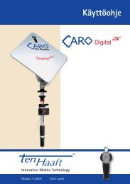
2. Platzbedarf der Oyster 65- und 85-Anlage / required space for the Oyster 65- and 85 system /<br />
Encombrement des Oyster 65 et 85:<br />
Ach<strong>ten</strong> Sie darauf, dass für die zusammengeklappte Oyster Digital sowie für den Aktionsradius (Drehradius) ausreichend<br />
Platz vorhanden ist.<br />
Generell wird folgender Platz für die zusammengeklappte Oyster Digital benötigt: Hal<strong>ten</strong> Sie den unmontier<strong>ten</strong> Spiegel<br />
probeweise über den Spiegelarm und planen Sie von Dach bis Spiegelunterkante 9 cm Höhe ein. Die Oyster muss später<br />
so montiert sein, dass das LNB zum Fahrzeugheck zeigt (siehe Zeichnung).<br />
Take care, that there is enough spare for the fold Oyster DIGITAL just as for the Operating range (cruising radius). In<br />
general, this of space for a folded OYSTER Digital is needed: Take a not mounted satellite dish for test purposes above the<br />
satellite dish arm holder and calculate a height of 9 cm between roof and under edge of the satellite dish. The OYSTER<br />
has to be later mounted so, that the LNB points to the rear of the vehicle. (See drawing)<br />
Veillez à ce qu´une surface suffisante soit disponible aussi bien pour l´an<strong>ten</strong>ne Osyter numérique repliée que pour son<br />
rayon d´action (rotation).<br />
En général, voilà la place nécessaire à l´an<strong>ten</strong>ne repliée : Pour essayer, <strong>ten</strong>ez la parabole démontée au-dessus du bras de<br />
l´an<strong>ten</strong>ne et prévoyez 9 cm de hauteur entre le toit et le bord inférieur de l´an<strong>ten</strong>ne. Plus tard l´Oyster sera montée de<br />
façon à ce que le LNB paraisse à l´arrière du véhicule (voir croquis)<br />
Oyster 85: 111,5 cm<br />
O<br />
y<br />
s<br />
t<br />
e<br />
r<br />
Oyster 65: 91,5 cm<br />
37 cm<br />
Oyster 65:<br />
72 cm<br />
Oyster 85:<br />
92 cm<br />
Fahrtrichtung<br />
driving direction<br />
sens de la marche<br />
9<br />
Abbildung 1: Draufsicht auf eine Oyster<br />
Digital Anlage<br />
Picture 1: top view on an OYSTER System<br />
Image 1: vue au-dessus système Oyster
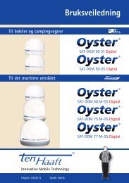
Für den Aktionsradius beim Drehen der Oyster® Digital, muss erst ab einer Höhe von 135 mm ab Dachoberkante Platz<br />
vorgesehen werden. Das bedeutet, Dachaufbau<strong>ten</strong> wie z.B. Klimaanlagen, Dachfenster in geöffnetem Zustand, Dachkoffer<br />
usw. müssen sich ab dieser Höhe außerhalb des un<strong>ten</strong> angegebenen Aktionsradius befinden. Gegenstände, welche niedriger<br />
als 135 mm ab Dachoberkante sind, wie z.B. die meis<strong>ten</strong> Dachrelingar<strong>ten</strong>, können sich auch innerhalb des Aktionsradius<br />
befinden und schränken diesen nicht ein.<br />
For the operating range of the Oyster® Digital, there has to considered space only from 135 mm height, above the edge<br />
of the roof vehicle. This means, that items of the roof system - like air condition, open roof-lights, luggage boxes etc.<br />
- which do exceed this height of 135 mm , have to outside of the indicated operating range. Items less than 135 mm<br />
height, like the most roof railings, can be inside this range without constricting it.<br />
C´est à partir d´une hauteur de 135 mm à partir du bord supérieur du toit qu´il faudra prévoir une surface nécessaire<br />
utile au rayon d´action. Cela signifie qu´à partir de cette hauteur toutes les installations montées sur le toit telles que la<br />
climatisation, les luca rnes en position ouvertes, box, etc...devront se trouver à l´extérieur du rayon de rotation mentionné.<br />
Les objets d´une hauteur inférieure à 135 mm du bord supérieur du toit, comme par exemple la plupart des batayoles<br />
peuvent se trouver à l´intérieur du rayon d´action sans pour autant gêner sa rotation.<br />
Fahrzeugheck<br />
vehicle rear<br />
vehicule arrière<br />
O<br />
y<br />
s<br />
t<br />
e<br />
r<br />
11cm<br />
Drehpunkt / center of rotation / point de rotation<br />
Abbildung 2: Aktionsradius der Oyster Digital 65- und 85- Anlage<br />
Picture 2: Operating range of the Oyster 65- and 85 System<br />
Image 2: Rayon d´action de la Oyster Digital 65- et 85- système<br />
~ 111,5 cm<br />
~ 7,8 cm<br />
~ 50 cm<br />
~ 15,9<br />
cm<br />
10<br />
Fahrtrichtung<br />
driving direction<br />
sens de la marche<br />
Radius Oyster 65: 54 cm (ab 13,5cm bis 55cm Höhe)<br />
radius Oyster 65: 54 cm (from 13,5cm to 55cm height)<br />
rayon Oyster 65: 54 cm (de 13,5cm à 55cm hauteur)<br />
Radius Oyster 85: 65 cm (ab 13,5cm bis 55cm Höhe)<br />
radius Oyster 85: 65 cm (from 13,5cm to 55cm height)<br />
rayon Oyster 85: 65 cm (de 13,5cm à 55cm hauteur)<br />
~ 23 cm<br />
Abbildung 3: Oyster Digital 85-Anlage<br />
Picture 3: Oyster 85 System<br />
Image 3: Oyster Digital 85-système
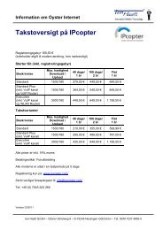
3. Platzbedarf der CARO Digital Anlage / required space for the CARO Digital system /<br />
Encombrement des CARO Digital système<br />
Ach<strong>ten</strong> Sie darauf, dass für die zusammengeklappte CARO Digital Anlage sowie für den Aktionsradius (Drehradius) ausreichend<br />
Platz vorhanden ist.<br />
Take care, that there is enough spare for the fold CARO Digital, just as for the Operating range (cruising radius).<br />
Veillez à ce qu´une surface suffisante soit disponible aussi bien pour la CARO Digital repliée que pour son rayon d´action<br />
(rotation).<br />
75 cm<br />
55 cm<br />
~ 19 cm<br />
A<br />
Radius 31cm bis Aufbau<strong>ten</strong>höhe 10cm<br />
radius 31cm up to a height of 10cm<br />
rayon 31cm jusqu´à une hauteur de 10cm<br />
Abbildung 4: Aktionsradius der CARO Digital Anlage<br />
Picture 4: operating radius CARO Digital system<br />
Image 4: rayon d´action du CARO Digital système<br />
Fahrzeugheck<br />
vehicle rear<br />
vehicule arrière<br />
Steckergehäuse<br />
plug casing<br />
Boîtier à prises<br />
~ 36 cm<br />
Fahrtrichtung<br />
driving direction<br />
sens de la marche<br />
55 cm<br />
11<br />
Mitte der Dreheinheit<br />
center of the rotation unit<br />
centre de l´unité de rotation<br />
Aktionsradius<br />
operating radius<br />
rayon d´action<br />
Radius / rayon<br />
45cm<br />
C<br />
Radius / rayon<br />
39cm<br />
B<br />
Radius / rayon<br />
31cm<br />
A<br />
C<br />
Radius 45cm bis Aufbau<strong>ten</strong>höhe 22cm<br />
radius 45cm up to a height of 22cm<br />
rayon 45cm jusqu´à une hauteur de 22cm<br />
10cm<br />
17cm<br />
22cm
4. Platzbedarf der COSMO-Anlage / required space for the COSMO Digital system /<br />
Encombrement des COSMO Digital système<br />
Ach<strong>ten</strong> Sie darauf, dass für die zusammengeklappte COSMO Digital Anlage sowie für den Aktionsradius (Drehradius)<br />
ausreichend Platz vorhanden ist.<br />
Take care, that there is enough spare for the fold COSMO Digital, just as for the Operating range (cruising radius).<br />
Veillez à ce qu´une surface suffisante soit disponible aussi bien pour la Cosmo numérique repliée que pour son rayon<br />
d´action (rotation).<br />
Fahrzeugheck<br />
vehicle rear<br />
vehicule arrière<br />
Drehzentrum<br />
Fahrtrichtung<br />
center of rotation driving direction<br />
centre de rotation sens de la marche<br />
Radius / rayon 38 cm<br />
77 cm<br />
50 cm<br />
16 cm<br />
12<br />
37 cm<br />
63 cm<br />
Radius / rayon<br />
33 cm<br />
Radius / rayon<br />
26 cm<br />
Radius /<br />
rayon<br />
19 cm<br />
15 cm<br />
20 cm<br />
30 cm<br />
Das bedeutet z. B., dass sich bis zu einem Radius von 19 cm<br />
nichts befinden darf, ab einem Radius von 19 bis 26 cm keine<br />
Gegenstände, die höher sind als 15 cm, ab einem Radius von 26<br />
cm bis 33 cm keine Gegenstände die höher sind als 20 cm, etc.<br />
This means, within a radius of 19 cm nothing; from radius 19<br />
up to 26 cm no items higher than 15 cm are allowed, from<br />
radius 26 up to 33 cm no items higher than 20 cm, etc.<br />
Cela signifie que jusqu´à 19 cm de rayon rien ne devra s´y<br />
trouver, qu´à partir de 19 à 26 cm de rayon aucun objet plus<br />
haut que 15 cm, et à partir de 26 cm à 33 cm de rayon aucun<br />
objet plus haut que 20 cm etc.
5. Platzbedarf der SAMY-Anlage / required space for the SAMY Digital system /<br />
Encombrement des SAMY Digital système<br />
Ach<strong>ten</strong> Sie darauf, dass für die zusammengeklappte SAMY Digital Anlage sowie für den Aktionsradius (Drehradius)<br />
ausreichend Platz vorhanden ist.<br />
Take care, that there is enough spare for the fold SAMY Digital, just as for the Operating range (cruising radius).<br />
Veillez à ce qu´une surface suffisante soit disponible aussi bien pour la Cosmo numérique repliée que pour son rayon<br />
d´action (rotation).<br />
Fahrzeugheck<br />
vehicle rear<br />
vehicule arrière<br />
63 cm<br />
Drehzentrum<br />
center of rotation<br />
centre de rotation<br />
88 cm<br />
Fahrtrichtung<br />
driving direction<br />
sens de la marche<br />
15,5 cm<br />
13<br />
Radius / rayon 70 cm<br />
Radius / rayon<br />
55 cm<br />
Radius /<br />
rayon<br />
40 cm<br />
15 cm<br />
35 cm<br />
Das bedeutet z. B., dass sich bis zu einem Radius von 40<br />
cm nichts befinden darf, ab einem Radius von 40 bis 55<br />
cm keine Gegenstände, die höher sind als 15 cm, ab einem<br />
Radius von 55 cm bis 70 cm keine Gegenstände die höher<br />
sind als 35 cm, etc.<br />
This means, within a radius of 40 cm nothing; from radius<br />
40 up to 55 cm no items higher than 15 cm are allowed,<br />
from radius 55 up to 70 cm no items higher than 35 cm,<br />
etc.<br />
Cela signifie que jusqu´à 40 cm de rayon rien ne devra s´y<br />
trouver, qu´à partir de 40 à 55 cm de rayon aucun objet<br />
plus haut que 15 cm, et à partir de 55 cm à 70 cm de<br />
rayon aucun objet plus haut que 35 cm etc.
Montageplatte montieren<br />
Mounting of the assembly plate<br />
Pose de la plaque de fixation<br />
Nachdem nun der endgültige Montageplatz der Anlage feststeht und Sie sich nochmals von der korrek<strong>ten</strong> Lage in<br />
Bezug auf die Fahrtrichtung überzeugt haben (Kabelauslass der Anlage zeigt in Richtung Fahrzeugheck), markieren<br />
Sie die Eckpunkte der Montageplatte.<br />
Nehmen Sie das System jetzt nach Lösen der vier Befestigungsmuttern durch Anheben von der Montageplatte ab.<br />
Die Montageplatte wird auf dem Fahrzeugdach mit handelsüblicher Karosserieklebedichtmasse verklebt und anschließend<br />
verschraubt. Für die Reinigung von Montageplatte und Dach verwenden Sie bitte ein spezielles Reinigungsmittel,<br />
welches vom Hersteller der stark klebenden Karosseriedichtmasse (z.B. Sikaflex, Teroson 1K-Pur, Würth<br />
„Klebt und Dichtet“) empfohlen wird. Tragen Sie nach Ablüf<strong>ten</strong> des Reinigers die Dichtmasse auf die Unterseite der<br />
Montageplatte auf und verschrauben Sie diese nach dem Aufsetzen auf das Dach mit den beiliegenden Blechschrauben<br />
(siehe Zeichnung).<br />
Beach<strong>ten</strong> Sie hinsichtlich der Verarbeitungszeit und der Trocknungszeit die Angaben des Herstellers der Klebedichtmasse,<br />
bevor Sie das Fahrzeug bewegen!<br />
Once you have determined the final installation position of the system and you have checked again that it is correctly<br />
positioned in relation to the driving direction (cable outlet pointing towards the rear of the vehicle), mark the corner<br />
points of the mounting plate.<br />
Next, undo the four retaining nuts and lift the system off the mounting plate.<br />
The mounting plate is bonded to the roof of the vehicle using commercially available highly adhesive body sealing<br />
compound and is then secured by screws. Please use a special cleaning agent to clean the mounting plate and roof as<br />
recommended by the manufacturer of the body sealing compound (e.g. Sikaflex, Teroson 1K-Pur, Würth Klebt und Dichtet).<br />
Once the cleaner has dried off, apply the sealing compound to the underside of the mounting plate. After fitting the<br />
mounting plate, secure it to the roof using the self-tapping screws provided (see drawing).<br />
Take note of the manufacturer’s instructions regarding processing and curing times of the adhesive sealing compound<br />
before moving the vehicle!<br />
Vehicle roof<br />
Klebedichtung<br />
Fahrzeugdach<br />
Montageplatte<br />
Sealing compound<br />
Assembly plate<br />
Fahrzeugheck Fahrtrichtung<br />
Rear of vehicle Driving direction<br />
14
Une fois que vous avez défini l´emplacement définitif du système et que vous avez vérifié que l´emplacement était<br />
correct par rapport au sens de déplacement du véhicule (sortie de câblage du système orientée vers l´arrière du véhicule)<br />
repérez les angles de la plaque de fixation.<br />
Retirez main<strong>ten</strong>ant le système de la plaque de fixation après avoir desserré les quatre écrous de fixation.<br />
La plaque de fixation doit être collée sur le toit du véhicule au moyen d´un adhésif d´étanchéité de carrosserie acheté<br />
dans le commerce puis vissée. Pour le nettoyage de la plaque et du toit utilisez le produit de nettoyage spécialement<br />
recommandé par le fabricant de l´adhésif (x. : Sikaflex, Teroson à 1 composant polyuréthane, adhésif klebt und dichtet<br />
Würth) Après séchage du produit de nettoyage, appliquez l´adhésif d´étanchéité sur le dessous de la plaque de fixation,<br />
positionnez la plaque sur le toit et vissez-la avec les vis à tôles fournies (voir dessin)<br />
Suivez les indications du fabricant de l‘adhésif d‘étanchéité concernant les temps d’utilisation et de séchage avant<br />
de prendre la route !<br />
Adhésif d´ étanchéité<br />
Plaque de xation<br />
Toit de véhicule<br />
Arrière du véhicule Sens du conduite<br />
15
System aufsetzen<br />
Locating the external unit<br />
Mise en place du système<br />
Setzen Sie die Außeneinheit auf die Montageplatte so auf, dass das Steckergehäuse und der Kabelauslass der Außeneinheit<br />
zum Fahrzeugheck zeigen. Mit 4 Muttern festschrauben und die kleinen Abdeckungen aufsetzen. Jede andere<br />
Position der Anlage ist nicht zulässig und führt zum Erlöschen der Gewährleistung. Wurde die Montageplatte vorher<br />
richtig montiert, so zeigen das LNB und der Kabelauslass jetzt in Richtung Fahrzeugheck.<br />
Befestigen der Winkelverschraubung (Dachdurchführung)<br />
Die Winkelverschraubung muss auf dem Fahrzeugdach so montiert werden, dass sie in Richtung Fahrzeugheck<br />
zeigt und dementsprechend der Kabeleingang spritzwassergeschützt hin<strong>ten</strong> liegt.<br />
Für eine unkomplizierte Kabelverlegung innerhalb des Fahrzeugs ist es von Vorteil, die Entfernung zwischen Winkelverschraubung<br />
und Bedienteil sowie Receiver so kurz wie möglich zu hal<strong>ten</strong>.<br />
a) Fertigen Sie für die Kabeldurchführung einen Dachdurchbruch mit ca.<br />
20-30 mm Durchmesser an.<br />
Winkelverschraubung<br />
ø 20-30 mm<br />
b) Verlegen Sie das Kabel ordentlich auf dem Fahrzeugdach z.B. in einem<br />
Kabelkanal und führen dann das aus der Winkelverschraubung kommende<br />
Kabel nach un<strong>ten</strong> zum Bedienteil.<br />
c) Die kleine Montageplatte für die Winkelverschraubung wird auf dem<br />
Fahrzeugdach mit handelsüblicher Karosserieklebedichtmasse verklebt und<br />
anschließend verschraubt. Für die Reinigung der kleinen Montageplatte<br />
und des Daches verwenden Sie bitte ein spezielles Reinigungsmittel, welches<br />
vom Hersteller der stark klebenden Karosseriedichtmasse (z.B. Sikaflex,<br />
Teroson 1K-Pur, Würth Klebt und dichtet) empfohlen wird. Tragen Sie nach<br />
Ablüf<strong>ten</strong> des Reinigers die Dichtmasse auf die Unterseite der Montageplatte<br />
auf und verschrauben Sie diese nach dem Aufsetzen auf das Dach mit den<br />
beiliegenden 4 Blechschrauben.<br />
16
Drehen Sie die Hutmutter der Winkelverschraubung erst zu, nachdem Sie die Kabellänge auf dem Dach angepasst haben*.<br />
Abdichtung der Dachdurchführung<br />
Sikaflex auf<br />
Schrauben<br />
und Muttern<br />
Sikaflex<br />
rundum<br />
Wichtig:<br />
Nach Abdichtung und<br />
Trocknung unbedingt<br />
Dichtigkeitsprüfung vornehmen<br />
*Kabellänge auf dem<br />
Dach anpassen<br />
d) Dich<strong>ten</strong> Sie den unteren Rand der Winkelverschraubung sowie die<br />
Blechschrauben ebenfalls mit Dichtmasse durchgehend rundum ab.<br />
e) Sollte das Kabel innerhalb des Fahrzeugs zu lang sein, können Sie es auch<br />
aufwickeln.<br />
Prüfen Sie abschließend die Dichtigkeit an der Kabeleinführung, an den Blechschrauben und am Fuß der Winkelverschraubung.<br />
17
Place the external unit on the mounting plate with the connector housing and the cable outlet of the external unit<br />
facing towards the rear of the vehicle. Screw down the 4 nuts and put on the small covers. An installation in any other<br />
position is not permitted and will cause the warranty to be invalidated.<br />
When the mounting plate is positioned correctly, the LNB and the connecting cable outlet must point towards the rear of<br />
the vehicle.<br />
Attaching the threaded elbow fitting (cable feed-through)<br />
The threaded elbow fitting on the roof must be located with the cable inlet pointing to the rear of the vehicle,<br />
thus protecting it against splash water.<br />
To make the routing of the cables inside the vehicle easier, the distance between the elbow fitting and the control panel<br />
and the receiver should be as short as possible.<br />
a) Fabricate a hole of 20 to 30 mm diameter in the roof for the cable feed-through.<br />
Elbow connector<br />
ø 20-30 mm<br />
b) Route the cable tidily on the roof of the vehicle (e.g. using a cable duct) and<br />
guide the cable coming out of the threaded elbow fitting downwards to the<br />
control panel.<br />
c) The small mounting plate of the threaded elbow fitting is bonded to the roof<br />
of the vehicle using commercially available body sealing compound and is<br />
then secured to the roof with screws. Please use a special cleaning agent to<br />
clean the mounting plate and roof as recommended by the manufacturer of a<br />
highly adhesive body sealing compound (e.g. Sikaflex, Teroson 1K-Pur, Würth<br />
Klebt und Dichtet). Once the cleaner has dried off, apply the sealing<br />
compound to the underside of the mounting plate. After fitting the mounting<br />
plate, secure it to the roof using the 4 supplied self-tapping screws.<br />
18
Do not tigh<strong>ten</strong> the union nut of the elbow fitting before having adjusted the length of the cable on the roof*.<br />
Dealing of the lead - through roof<br />
Sikaflex on<br />
screws and<br />
screw nuts<br />
Important:<br />
After sealing and drying -<br />
verify the impermeability!<br />
Sikaflex<br />
all around<br />
*Cabel length to adapt<br />
on the roof<br />
d) Use the sealing compound to seal all around the lower edge of the threaded<br />
elbow joint and the self-tapping screws.<br />
e) The cable can be coiled up if it is too long inside the vehicle.<br />
Check the cable inlet, the self-tapping screws and the foot of the threaded elbow fitting for leaks.<br />
19
Positionner l’unité extérieure sur la plaque de fixation de telle sorte que le boîtier de connecteurs et la sortie de câblage<br />
de l‘unité extérieure soient orientés vers l‘arrière du véhicule. Serragez avec les 4 noix et mettez les petites couvrirs.<br />
Toute autre position du système est interdite et entraîne l’annulation de la garantie.<br />
Lorsque la plaque de fixation a été correctement montée, le LNB et la sortie de câblage sont orientées vers l‘arrière du<br />
véhicule.<br />
Fixation du raccordement coudé (traversée de toit)<br />
Le raccordement coudé doit être monté sur le toit du véhicule de telle sorte qu’il soit orienté vers l’arrière du<br />
véhicule et que l’entrée de câblage se trouve donc à l‘arrière, protégée contre les projections d‘eau.<br />
Pour faciliter le câblage à l´intérieur du véhicule, il est important que le raccordement coudé, le boîtier de commande<br />
ainsi que le récepteur soient le plus près possible les uns des autres.<br />
a) Pour la traversée de câble, découpez une ouverture d’ environ 20-30 mm de diamètre dans le toit.<br />
Raccordement coudé<br />
ø 20-30 mm<br />
b) Posez proprement le câble sur le toit du véhicule (dans un conduit de câbles par exemple) et faites passer le<br />
câble sortant du raccordement coudé vers le bas jusqu’au boîtier de commande.<br />
c) La petite plaque de fixation pour le raccordement coudé doit être collée sur le toit du véhicule avec de<br />
l’adhésif d’étanchéité de carrosserie du commerce puis vissée. Pour le nettoyage de la petite plaque de fixation<br />
et du toit, utilisez le produit de nettoyage spécial recommandé par le fabricant de l’adhésif d’étanchéité de<br />
carrosserie à fort pouvoir adhésif (ex : Sikaflex, Teroson à 1 composant polyuréthane, adhésif « Klebt und<br />
Dichtet » Würth). Après séchage du produit de nettoyage, appliquez l’adhésif d’étanchéité sur<br />
le dessous de la plaque de fixation, positionnez la plaque sur le toit et vissez-la au moyen des 4 vis à<br />
tôle fournies.<br />
20
Ne serrez pas l’écrou borgne du raccordement coudé avant d´avoir adapté la longueur du câble au toit*.<br />
Etanchéisation de la traversée de toit<br />
Sikaflex sur<br />
les vis et<br />
écrous<br />
Important:<br />
Après étanchéisation et<br />
séchange, impérativement<br />
contôler l´étanchéité.<br />
Sikaflex tout<br />
autour<br />
*adapter la longueur du<br />
câble sur le toit<br />
d) Posez de l’adhésif d’étanchéité sur tout le bord inférieur du raccordement<br />
coudé ainsi que tout autour des vis à tôle.<br />
e) Si le câble est trop long à l’intérieur du véhicule, vous pouvez aussi l’enrouler.<br />
Veuillez vérifier l´étanchéité de la conduite du câble, des vis parker, et autour du pied du raccordement coudé<br />
21
Spannungsversorgung<br />
Power supply<br />
Alimentation électrique<br />
1. Sorgen Sie für eine ausreichende Spannungsversorgung des Systems<br />
a) Die Anlage benötigt den Anschluss an 12 V oder 24 V Bordspannung.<br />
b) Zum Anschluss an die Bordspannung darf der Kabelquerschnitt 2,5 mm² nicht unterschrei<strong>ten</strong>. Verwenden Sie ab 6 m<br />
Kabellänge einen Querschnitt von mindes<strong>ten</strong>s 4,0 mm².<br />
c) Der Anschluss an die Bordspannung über bestehende Leitungen ist in aller Regel nicht ideal. Oftmals ist der<br />
Kabelquerschnitt zu gering und / oder bereits andere Verbraucher wie z.B. der Fernseher, werden über diese<br />
Leitungen versorgt. Die zur Verfügung stehende Spannung reicht dann meist nicht aus.<br />
d) Empfehlenswert und gleichzeitig die optimale Lösung ist, eine separate Bordspannungsleitung für die Anlage zur<br />
Batterie zu verlegen.<br />
Die batterieseitige Absicherung dieser Leitung muss zwischen 10 und 20 A betragen.<br />
2. Spannungsversorgung in Caravans / Wohnanhängern<br />
In Caravans steht häufig keine stabile bzw. batteriegepufferte 12V Bordnetzversorgung zur Verfügung. In diesem Fall<br />
ist es notwendig, die Anlage über einen geeigne<strong>ten</strong> Spannungswandler 220V/12V aus dem Wechselspannungsnetz zu<br />
versorgen.<br />
Verwenden Sie keinesfalls Batterieladegeräte, einfache Transformatoren oder ungeregelte Netzteile. Geeignet sind<br />
ausschließlich elektronisch geregelte Festspannungsnetzteile mit einer Nennspannung von 13,8V und einer<br />
Dauerstrombelastbarkeit vom mindes<strong>ten</strong>s 6A.<br />
Wir empfehlen den Einsatz des von uns zu beziehenden Zusatzwandlers.<br />
1. Provide for a sufficient power supply of the system.<br />
a) The system requires connection to 12 V or 24 V on-board power.<br />
b) For the connection to the on-board power, the cable diameter must not be below 2.5 mm². For cable lengths of 6 m<br />
or more, use a cross section of at least 4.0 mm².<br />
c) In most cases, a connection to the on-board power over existing lines is not ideal. Of<strong>ten</strong> the cable diameter is too<br />
low and/or different users, e.g. the television set, are already being supplied via these lines. The available voltage is<br />
then usually not sufficient.<br />
d) Recommended and at the same time the optimal solution is to install a separate on-board power line for the unit to<br />
the battery.<br />
The fuse protection (battery side) of this line must be between 10 and 20 A.<br />
2. Power supply in caravans / trailers<br />
In caravans there is frequently no stable and/or battery backed-up 12 V board power supply available. In this case it is<br />
necessary to supply the system via a suitable voltage transformer 220 V/12 V from the mains power net.<br />
Do not use under any circumstances battery chargers, simple transformers, or non-stabilized power packs. Suitable are<br />
exclusively electronically controlled stabilized power packs with a nominal voltage of 13,8 V and a permanent current<br />
load capability of at least 6 A.<br />
We strongly recommend the use of the auxiliary transducer which can be obtained from us.<br />
22
1. Veillez à ce que l’alimentation électrique du système soit suffisante<br />
a) Le système doit être relié à une <strong>ten</strong>sion de bord de 12 V ou 24 V.<br />
b) Pour le raccordement au réseau de bord, le câble utilisé ne doit pas avoir une section inférieure à 2,5 mm2. Si<br />
toutefois la longueur du câble dépasse 6 m, utilisez une section de 4,0 mm2 minimum.<br />
c) Dans tous les cas, le raccordement au réseau de bord par les lignes existantes n’est pas idéal. Souvent, la section<br />
du câble est insuffisante et/ou d‘autres consommateurs (comme le téléviseur) sont déjà alimentés par ces lignes.<br />
La <strong>ten</strong>sion disponible est alors insuffisante la plupart du temps.<br />
d) La solution optimale (et recommandée) consiste à poser une ligne de <strong>ten</strong>sion de bord séparée pour relier le système<br />
à la batterie.<br />
Cette ligne doit être protégée par un fusible compris entre 10 et 20 A (côté de la batterie).<br />
2. Alimentation électrique des caravanes<br />
Souvent, les caravanes ne disposent pas d’une alimentation par réseau de bord 12 V stable et/ou protégée par batterie.<br />
Dans ce cas, il convient d’alimenter le système à partir du réseau à courant alternatif via un convertisseur de <strong>ten</strong>sion 220<br />
V/12 V.<br />
Ne jamais utiliser un chargeur de batterie, un transformateur simple ou un bloc d’alimentation non régulé. Seuls conviennent<br />
les blocs d’alimentation à <strong>ten</strong>sion fixe à régulation électronique d’une <strong>ten</strong>sion nominale de 13,8 V et d’une<br />
in<strong>ten</strong>sité maximale admissible d’au moins 6 A.<br />
Nous vous recommandons d’utiliser le convertisseur auxiliaire figurant dans notre catalogue.<br />
23
Vision III<br />
1<br />
3<br />
7 6<br />
8<br />
Zeichnung für Oyster Vision III<br />
Drawing for Oyster Vision III<br />
Dessin pour Oyster Vision III<br />
3<br />
6<br />
2<br />
10<br />
10A 3A<br />
9<br />
1<br />
31/30/15<br />
SAT OUT<br />
SAT IN<br />
4<br />
5<br />
24<br />
11<br />
4<br />
14<br />
5<br />
13<br />
16<br />
2<br />
12<br />
17<br />
15
Anschlusskennzeichnung an der Steuerbox:<br />
1<br />
1<br />
2<br />
3<br />
4<br />
5<br />
6<br />
7<br />
8<br />
9<br />
10<br />
11<br />
12<br />
13<br />
14<br />
15<br />
16<br />
17<br />
2<br />
3<br />
4<br />
5<br />
6<br />
31 / 30 / 15<br />
Receiver<br />
SAT OUT<br />
An<strong>ten</strong>ne<br />
SAT IN<br />
Schließen Sie hier das mitgelieferte Stromversorgungskabel an.<br />
ACHTUNG!<br />
Stellen Sie vorher sicher, dass das Stromversorgungskabel am anderen Ende korrekt an das<br />
Stromnetz des Fahrzeuges angeschlossen ist, bei Falschpolung kann die Steuerbox zerstört<br />
werden!<br />
Schließen Sie hier den 4-poligen weißen Stecker des mitgeliefer<strong>ten</strong> Steuerkabels zur Außeneinheit<br />
an. (Steuerkabel und Koaxkabel zur Außeneinheit befinden sich gemeinsam in einer<br />
schwarzen Ummantelung)<br />
Schließen Sie hier das mitgelieferte Westernkabel (ähnlich einem Telefonkabel) an und stecken<br />
das andere Kabelende im Bedienteil ein.<br />
Verbinden Sie diese Buchse mit der Eingangsbuchse ihres Satelli<strong>ten</strong>receivers unter Verwendung<br />
des beiliegenden kürzeren Koaxkabels.<br />
Schließen Sie hier den An<strong>ten</strong>nenstecker (F-Stecker) des mitgeliefer<strong>ten</strong> Steuerkabels zur<br />
Außeneinheit an. (Steuerkabel und Koaxkabel zur Außeneinheit befinden sich gemeinsam in<br />
einer schwarzen Ummantelung)<br />
AUX-Relais optionaler Schaltkontakt für TV Gerät<br />
Fahrzeugheck<br />
Fahrtrichtung<br />
Winkelverschraubung<br />
Außeneinheit<br />
Montageplatte<br />
Sat-Zuleitung Länge 4,5 m ab Außeneinheit<br />
Bedienteil<br />
Westernkabel Länge 2,5m ab Steuerbox<br />
Sicherungen<br />
Vision III Steuergerät<br />
Receiver-Sat-Kabel-Ausgang Länge 1,5m ab Steuerbox<br />
Kabel (Schwarz)<br />
Receiver (nicht im Lieferumfang enthal<strong>ten</strong>)<br />
Kabel (Braun - Minuspol)<br />
Kabel (Rot - Pluspol)<br />
Aufbau-Batterie<br />
Zündung Klemme 15<br />
25
Connector identification at the control unit:<br />
1<br />
2<br />
3<br />
4<br />
5<br />
6<br />
7<br />
8<br />
9<br />
10<br />
11<br />
12<br />
13<br />
14<br />
15<br />
16<br />
17<br />
1<br />
2<br />
3<br />
4<br />
5<br />
6<br />
31 / 30 / 15<br />
Receiver<br />
SAT OUT<br />
an<strong>ten</strong>na<br />
SAT IN<br />
Connect here the provided power cable.<br />
ATTENTION!<br />
Make sure beforehand that the power cable is correctly connected to electricity mains of the<br />
vehicle at the other end; in case of wrong polarity the control unit can be destroyed!<br />
Connect here the white 15 pin plug of the provided control cable to the external unit. (Control<br />
cable and coax cable to the external unit are together in a black sheath.)<br />
Connect here the provided Western cable (similar to a telephone line), and plug the other cable<br />
end into the operating control device.<br />
Connect this socket with the input socket of your satellite receiver using the included shorter<br />
coax cable.<br />
Connect here the an<strong>ten</strong>na plug (F plug) of the provided control cable to the external unit.<br />
(Control cable and coax cable to the external unit are together in a black sheath.)<br />
AUX-Relais optional switch contact für TV device<br />
Rear of the vehicle<br />
Driving direction<br />
Elbow connector<br />
External unit<br />
Assembly plate<br />
Length 4.5 m from external unit<br />
Operating device<br />
Western cable length 6.5 m from Operating device<br />
fuse fixing<br />
Control unit<br />
Coax cable Length 1.5 m from control unit<br />
Cable (black)<br />
Receive (not comprised in scope of delivery)<br />
Cable (brown - minus pole)<br />
Cable (red - plus pole)<br />
On-board battery<br />
Ignition Pin 15<br />
26
Identification des connexions sur l’appareil de commande:<br />
1<br />
2<br />
3<br />
4<br />
5<br />
6<br />
7<br />
8<br />
9<br />
10<br />
11<br />
12<br />
13<br />
14<br />
15<br />
16<br />
17<br />
1<br />
2<br />
3<br />
4<br />
5<br />
6<br />
31 / 30 / 15<br />
Récepteur<br />
SAT OUT<br />
An<strong>ten</strong>ne<br />
SAT IN<br />
Branchez ici le câble d’alimentation fourni.<br />
ATTENTION !<br />
Assurez-vous au préalable que l’autre extrémité du câble d‘alimentation est correctement<br />
raccordée au réseau de bord du véhicule. Une erreur de polarité peut détruire l‘appareil de<br />
commande !<br />
Branchez ici le connecteur blanc à 15 broches du câble de commande fourni allant à l‘unité<br />
extérieure. (Le câble de commande et le câble coaxial allant à l’unité extérieure sont réunis<br />
dans une gaine noire).<br />
Branchez ici le câble Western fourni (ressemblant à un câble de téléphone) et l’autre extrémité<br />
du câble dans l‘appareil de commande.<br />
Reliez cette douille à la douille d’entrée de votre récepteur satellite au moyen du câble coaxial<br />
court fourni.<br />
Branchez ici le connecteur d’an<strong>ten</strong>ne (connecteur F) du câble de commande fourni allant à<br />
l‘unité extérieure. (Le câble de commande et le câble coaxial allant à l’unité extérieure sont<br />
réunis dans une gaine noire).<br />
AUX-Relais contact réglementation pour TV - optional<br />
Arrière du véhicule<br />
Sens de conduite<br />
Raccordement coudé<br />
Unité extérieure<br />
Plaque de fixation<br />
Longueur 4,5 m depuis l‘unité extérieure<br />
Appareil de commande<br />
Longueur 4 m entre l‘unité extérieure et la dérivation<br />
Porte-fusibles<br />
boîtier de commande<br />
Câble coaxial: longueur 1,5 m depuis l‘appareil de commande<br />
Câble (noir)<br />
Récepteur (non fourni)<br />
Câble (brun - pôle négatif)<br />
Câble (rouge - pôle positif)<br />
Batterie de cellule<br />
Borne 15<br />
27
Sicherheitsschaltung<br />
Protection circuit<br />
Circuit de sécurité<br />
Um Schäden durch ein versehentliches Fahren mit ausgeklappter Außeneinheit zu verhindern, muss die schwarze Leitung<br />
der Spannungsversorgung des Steuerbox mit der „Klemme 15“ verbunden werden (Klemme 15 ist eine Leitung, die<br />
bei eingeschalteter Zündung Spannung führt und bei ausgeschalteter Zündung keine Spannung). Die Anlage fährt dann<br />
automatisch ein, sobald die Zündung eingeschaltet wird.<br />
Außerdem lässt sich bei eingeschalteter Zündung die Anlage nicht ausfahren.<br />
Hinweis:<br />
Verwenden Sie zum Anschluss nur eine geschaltete Plusleitung, nicht die D-Plus Leitung der Lichtmaschine. Die D-Plus<br />
Leitung schaltet bei vielen Fahrzeugen keine saubere Gleichspannung durch, außerdem liegen auf dieser Leitung nicht<br />
sofort ca. 12 Volt an, sondern oftmals eine sich langsam aufbauende Spannung. Dies kann zu Funktionsproblemen beim<br />
Prozessor in der Steuerbox führen.<br />
Die Umsetzung dieses Hinweises ist vom Hersteller <strong>ten</strong> <strong>Haaft</strong> verbindlich vorgeschrieben!<br />
Ebenso die Funktionsprüfung durch den Monteur!<br />
In order to prevent damage by inadver<strong>ten</strong>tly driving with a folded-up external unit, the black line of the voltage supply of<br />
the receiver must be connected to „pin 15“ (pin 15 is a line which does lead voltage during switched-on ignition and no<br />
voltage with switched-off ignition). The unit will then automatically retract as soon as the ignition is switched on.<br />
In addition, the unit cannot be ex<strong>ten</strong>ded with switched-on ignition.<br />
Note:<br />
Use for the connection only a switched plus wire, not the D-plus line of the generator. With many vehicles, the D-plus<br />
line does not switch through a clean DC voltage; in addition there are not immediately available approx. 12 volts on this<br />
line but of<strong>ten</strong> a voltage is only slowly built up. This can lead to functional problems with the processor in the receiver.<br />
The implementation of this information is from the manufacturer <strong>ten</strong> <strong>Haaft</strong> mandatory!<br />
Likewise, the function test by the installer!<br />
Pour éviter des dommages dus à l’oubli de replier l’unité extérieure pendant la conduite, reliez le fil noir du câble<br />
d’alimentation électrique du récepteur à la borne 15 (la borne 15 est une ligne qui est sous <strong>ten</strong>sion lorsque le contact<br />
est établi et hors <strong>ten</strong>sion lorsque le contact est coupé). De cette manière, le système se rétracte automatiquement à<br />
l’établissement du contact.<br />
De plus, lorsque le contact est établi, le système ne peut pas se déployer.<br />
Conseil :<br />
Pour le raccordement, utilisez uniquement une ligne positive commutée, pas la ligne D+ de l’alternateur. Dans de nombreux<br />
véhicules, cette dernière ne fournit pas une <strong>ten</strong>sion continue de qualité. De plus, elle ne délivre pas immédiatement<br />
la <strong>ten</strong>sion 12 volts : cette valeur n’est souvent atteinte que progressivement, ce qui peut affecter le bon fonctionnement<br />
du processeur dans le récepteur.<br />
La mise en œuvre de cette information est tirée du fabricant <strong>ten</strong> <strong>Haaft</strong> obligatoire!<br />
De même, le test de fonctionnement par l‘installateur!<br />
28
Receiver-Anschluss<br />
Connecting the receiver<br />
Connexion du récepteur<br />
Schließen Sie die Anlage an Ihren Receiver (nicht im Lieferumfang enthal<strong>ten</strong>) an, in dem Sie den F-Stecker am weißen<br />
Koax-Kabel auf die F-Buchse des Sat-Eingangs schrauben<br />
Connect your system to your receiver (not included in scope of supply) by screwing the F-type connector of the white<br />
coaxial cable to the F-type port at the input of the satellite receiver.<br />
Vous pouvez main<strong>ten</strong>ant raccorder le système à votre récepteur (non fourni) en vissant le connecteur F du câble coaxial<br />
blanc sur la douille F de l’entrée satellite.<br />
29
Bedienung der Anlage (Kurzanleitung)<br />
Operating the system (quick reference)<br />
Utilisation de système (instructions sommaires)<br />
Beach<strong>ten</strong> Sie bitte vor dem Einschal<strong>ten</strong>, dass Sie freie Sicht nach Süden haben, denn sonst ist kein Satelli<strong>ten</strong>-<br />
Empfang möglich.<br />
1. Schal<strong>ten</strong> Sie Ihr TV-Gerät und den Receiver ein und stellen Sie am Receiver<br />
ein empfangbares Programm ein.<br />
2. Drücken Sie zum Einschal<strong>ten</strong> des Systems auf die Taste am Bedienteil.<br />
Alles weitere bis zur Bild-Übertragung funktioniert ab jetzt vollautomatisch.<br />
Die An<strong>ten</strong>ne fährt grundsätzlich zuerst in die letzte Empfangsposition.<br />
Benützen Sie die Anlage das erste Mal, bzw. haben Sie Ihren Standort gewechselt, so kann das System in der letz<strong>ten</strong><br />
Empfangsposition kein Bild auswer<strong>ten</strong> und es beginnt die „Vollautomatische Suche“. Anschließend erhal<strong>ten</strong> Sie sofort Ihr<br />
Fernsehbild.<br />
Haben Sie die Anlage an dem gleichen Standort und in der gleichen Fahrzeugposition schon einmal benützt, so empfängt<br />
sie ohne Suche sofort in der letz<strong>ten</strong> Empfangsposition.<br />
Deutschsprachiges Programm wird in der Regel über den Satelli<strong>ten</strong> Astra1 übertragen, der in den meis<strong>ten</strong> Teilen Europas<br />
auch mit der Spiegelgröße 65 cm empfangen werden kann.<br />
In manchen Regionen (z.B. in Griechenland, in der Türkei) strahlt der Satellit Astra keine ausreichenden Signale aus und<br />
kann daher nicht empfangen werden. Wählen Sie dann einen anderen Suchsatelli<strong>ten</strong>, z.B. Eutelsat-Hotbird (siehe ausführliche<br />
Bedienungsanleitung).<br />
Nach erfolgter Satelli<strong>ten</strong>findung schal<strong>ten</strong> Sie die Programme mit Ihrer Receiver-Fernbedienung um.<br />
Ausgeschaltet wird das System durch Drücken der Taste am Bedienteil. Die Anlage fährt dann ein und schaltet ab.<br />
1. Switch on your TV set and the receiver and select a receivable programme at<br />
the receiver.<br />
2. Press at the control panel to switch on the system.<br />
That‘s all you have to do – anything else required to receive a TV image will happen automatically.<br />
The an<strong>ten</strong>na will always move into the last reception position.<br />
If you use the system for the first time or if you have moved the system to a different location, the system will not receive<br />
a signal in this position and hence starts the „automatic search“. This will soon yield a TV picture.<br />
If you have used the system at the same location and in the same vehicle position before, then it will immediately receive<br />
signals without a prior search.<br />
English-language channels are mostly transmitted via Astra II, which can be received in most parts of Europe with a 85cm<br />
parabolic an<strong>ten</strong>na.<br />
In some regions (e.g. in Greece, Turkey) the Astra signals are too weak to be received. In this case, select a different<br />
search satellite such as Hotbird/Eutelsat (see comprehensive Operating Instructions).<br />
Once the satellite has been found, you can select channels with the remote control of your receiver.<br />
To switch off the system, press at the control panel. The an<strong>ten</strong>na will retract and the system will switch off.<br />
30
1. Allumez le téléviseur et sélectionnez une chaîne captable sur le récepteur.<br />
2. Pour mettre le système sous <strong>ten</strong>sion, appuyez sur la touche du boîtier<br />
de commande.<br />
Tout le reste, jusqu’à la transmission de l’image, s’effectue désormais de manière entièrement automatique.<br />
L’an<strong>ten</strong>ne commence par se placer dans la dernière position de réception.<br />
Si vous utilisez le système pour la première fois ou si votre véhicule a changé d’emplacement, le système ne peut restituer<br />
aucune image sur la dernière position de réception et la « recherche entièrement automatique » s’effectue.<br />
Vous recevez alors immédiatement l’image de télévision.<br />
Si vous l’avez déjà utilisé au même endroit et dans la même position du véhicule, le système reçoit immédiatement<br />
l’image sur la dernière position de réception, sans recherche.<br />
Les chaînes en langue française sont généralement diffusées par les satellites Astra 1, Eutelsat Hotbird ou AtlanticBird<br />
qui peuvent être captés un peu partout en Europe avec une an<strong>ten</strong>ne parabolique de 65 cm de diamètre.<br />
Dans certaines régions (comme une partie de la Grèce et en Turquie), le satellite Astra n’émet pas des signaux d’une force<br />
suffisante et ne peut donc pas être capté. Dans ce cas, choisissez un autre satellite à rechercher, comme Hotbird/Eutelsat<br />
(se reporter aux instructions d‘utilisation détaillées).<br />
Une fois le satellite localisé, changez de chaîne au besoin à l’aide de la télécommande du récepteur.<br />
On deconnecte le système en appuyant sur la touche de la commande. L´an<strong>ten</strong>ne se retracte et s´eteind.<br />
31
Demontage der Anlage<br />
Removal of the system<br />
Démontage du système<br />
Für die Demontage der Außeneinheit benötigen Sie zusätzlich einen Gabelschlüssel SW 13.<br />
Es ist nicht notwendig die Zuleitung zu demontieren.<br />
Gehen Sie wie folgt vor:<br />
l Lösen Sie die vier Muttern M8, welche die Grundplatte mit der Montageplatte<br />
verbinden. Dann heben Sie die Anlage ab.<br />
l Lösen Sie die vier Muttern M6 am Abdeckblech unterhalb des kleinen weißen<br />
Steckergehäuses und ziehen Sie das Abdeckblech heraus (je nach Modell).<br />
l Lösen Sie die Steckverbindung des Da<strong>ten</strong>- und des Stromkabels an den<br />
Steckern der Zuleitung.<br />
l Lösen Sie die Steckverbindung des Sat-Kabels durch Drehen gegen den<br />
Uhrzeigersinn an dem Stecker des Koax-Kabels der Zuleitung.<br />
l Jetzt können Sie die Anlage entfernen.<br />
Um die Anlage wieder zu montieren gehen Sie in der umgekehr<strong>ten</strong> Reihenfolge vor.<br />
The removal of the exterior unit requires a 13-mm open-end spanner.<br />
The supply line does not need to be removed.<br />
Proceed as follows:<br />
l Undo the four M8 nuts securing the base plate to the mounting plate. Lift off<br />
the system.<br />
l Remove the four M6 nuts at the cover panel below the small white connector<br />
housing and pull out the cover panel (depending on model).<br />
l Disconnect the data and power cables.<br />
l Disconnect the satellite cable by rotating the connector counter-clockwise.<br />
l The system can now be removed.<br />
To reinstall the unit, perform the steps above in reversed order.<br />
Pour démonter l’unité extérieure, vous aurez en plus besoin d’une clé à fourche de 13 mm.<br />
Il n’est pas nécessaire de démonter la ligne d’alimentation.<br />
Procédez comme suit:<br />
l Desserrez les quatre écrous M8 qui fixent la plaque de base sur la plaque de<br />
fixation puis détachez le système.<br />
l Desserrez les quatre écrous M6 sur le panneau de protection sous le petit<br />
boîtier de connecteurs blanc et retirez le panneau (Selon le modèle).<br />
l Détachez les connecteurs des câbles de données et d’alimentation.<br />
l Détachez le connecteur du câble satellite en tournant dans le sens contraire<br />
des aiguilles d’une montre le connecteur du câble coaxial de la ligne<br />
d’alimentation.<br />
l Vous pouvez main<strong>ten</strong>ant retirer le système.<br />
Pour reposer le système, procédez dans l’ordre inverse .<br />
32
Erste Hilfe bei Störungen<br />
First help with malfunctions<br />
Premières mesures à prendre en cas d’anomalie<br />
Beim Betrieb der automatischen An<strong>ten</strong>neneinheit kann es zu Störungen kommen, wenn z.B. die Bewegungsfreiheit der<br />
An<strong>ten</strong>ne nicht gewährleistet ist (Äste, Schnee etc.).<br />
Derartige Störungen werden zum Teil automatisch erkannt und auf dem Display des Bedienteils dargestellt<br />
Fehlerbeschreibung Störungsbeseitigung<br />
Bei der Suche nach einem<br />
Satelli<strong>ten</strong> konnte kein Signal<br />
empfangen werden.<br />
Im Display erscheint „YMotor-<br />
Fehler“ oder „XMotor-<br />
Fehler“<br />
An<strong>ten</strong>ne reagiert nach dem<br />
Einschal<strong>ten</strong> nicht oder reagiert<br />
nicht auf Kommandos.<br />
Haben Sie freie Sicht nach Süden?<br />
Sind Sie im Empfangsbereich des eingestell<strong>ten</strong> Suchsatelli<strong>ten</strong>?<br />
Müsste aufgrund Ihres Standorts der Skew-Winkel des LNB geändert werden (siehe<br />
Bedienungsanleitung)<br />
Ragen Gegenstände in den Bewegungsbereich der An<strong>ten</strong>ne?<br />
Ist die Versorgungsspannung zu gering (Batterie schwach)?<br />
Ist die Sicherung in Ordnung?<br />
Sind alle Kabel ordnungsgemäß eingesteckt.<br />
During the operation of the automatic an<strong>ten</strong>na system there might occur malfunctions, e.g. if the unobstructed movement<br />
of the an<strong>ten</strong>na is not ensured (branches, snow etc.).<br />
In part, such malfunctions are automatically identified and represented on the display of the control device.<br />
Error description Fault correction<br />
During the search for a<br />
satellite, no signal could be<br />
received.<br />
„Y motor error“ or „X motor<br />
error“ appears in the<br />
display.<br />
An<strong>ten</strong>na does not react after<br />
switching on, or does not<br />
react to commands.<br />
Do you have free line of view towards the south?<br />
Are you within the reception range of the selected search satellite?<br />
Should the skew angle of the LNB be modified with reference to your location?<br />
Are any objects interfering with the movement of the an<strong>ten</strong>na? Is the supply<br />
voltage too low (weak battery)?<br />
Is the fuse OK?<br />
Are all cables correctly plugged in?<br />
33
Pendant l’utilisation de l’unité d’an<strong>ten</strong>ne automatique, des anomalies peuvent survenir lorsque par exemple la liberté de<br />
mouvement de l’an<strong>ten</strong>ne n’est plus assurée (branches, neige, etc.).<br />
Certaines de ces anomalies sont automatiquement détectées et signalées sur l’écran de l’appareil de commande.<br />
Description de l’anomalie Remède<br />
Aucun signal n’a été reçu lors de<br />
la recherche d’un satellite<br />
Le message « erreur de moteur<br />
Y » ou « erreur de moteur X »<br />
apparaît dans l’affichage<br />
L’an<strong>ten</strong>ne ne réagit pas après la<br />
mise sous <strong>ten</strong>sion ou ne répond<br />
pas aux commandes.<br />
La vue vers le sud est-elle dégagée ?<br />
Vous trouvez-vous dans la zone de réception du satellite défini ?<br />
L’angle d’obliquité de la tête de réception a-t-il dû être modifié en raison de votre<br />
emplacement ?<br />
Des objets dépassent-ils dans le rayon de rotation de l’an<strong>ten</strong>ne ? La<br />
<strong>ten</strong>sion d’alimentation est-elle trop faible (batterie déchargée) ?<br />
Le fusible est-il grillé ?<br />
Tous les câbles sont-ils correctement branchés ?<br />
34
Hinweise zum Umweltschutz<br />
Notes on the protection of the environment<br />
Consignes sur la protection de l´environnement<br />
Dieses Produkt darf am Ende seiner Lebensdauer nicht über den normalen Haushaltsabfall entsorgt<br />
werden, sondern muss an einem Sammelpunkt für das Recycling von elektrischen und elektronischen<br />
Gerä<strong>ten</strong> abgegeben werden. Das Symbol auf dem Produkt, der Gebrauchsanleitung oder der Verpackung<br />
weist darauf hin.<br />
Die Werkstoffe sind gemäß ihrer Kennzeichnung wiederverwertbar. Mit der Wiederverwertung, der<br />
stofflichen Verwertung oder anderen Formen der Verwertung von Altgerä<strong>ten</strong> leis<strong>ten</strong> Sie einen wichtigen<br />
Beitrag zum Schutze unserer Umwelt. Bitte erfragen Sie bei der Gemeindeverwaltung die zuständige<br />
Entsorgungsstelle.<br />
Altfahrzeugverordnung - ELV<br />
Das An<strong>ten</strong>nen-System ist als Zubehör zur Verwendung auf Kraftfahrzeugen zertifiziert und vorgesehen. Die Entsorgung<br />
kann demgemäß im Rahmen der Altfahrzeug-Verordnung (Europäische Altfahrzeugrichtlinie ELV, 2000/ 53/EG; für<br />
Deutschland: AltfahrzeugV) zusammen mit dem Kraftfahrzeug erfolgen. Das An<strong>ten</strong>nen-System enthält keine der gemäß<br />
Richtlinie als umweltschädlich eingestuf<strong>ten</strong> Stoffe.<br />
Abschließend wünschen wir Ihnen viel Freude mit Ihrem neuen <strong>ten</strong> <strong>Haaft</strong> Produkt!<br />
At the end of its lifecycle, this product must not be disposed of with your normal waste, but instead<br />
must be returned to a recycling facility for electric and electronic devices. This is indicated by the<br />
symbol on the product, the operating manual or the packaging.<br />
The materials can be reused in accordance with their identification. By reusing or recycling old equipment<br />
or making use of it in other ways you are making an important contribution to protecting our<br />
environment. Please contact your local council to find out where your nearest disposal facility is.<br />
EC End-of-Life Vehicle Directive<br />
The an<strong>ten</strong>na-system is certified and in<strong>ten</strong>ded for use as an accessory of a motor vehicle. The system may be disposed of<br />
together with the vehicle in accordance with the End-of-Life Vehicle Directive ELV, 2000/53/EC. an<strong>ten</strong>na-system does not<br />
contain any materials rated as hazardous to the environment according to the directive.<br />
We hope you get a lot of enjoyment out of your new <strong>ten</strong> <strong>Haaft</strong> product!<br />
35
Á la fin de sa vie, ce produit ne devra pas être éliminé avec les déchets ménagers habituels. Il devra<br />
être déposé dans un point de collecte spécifique au recyclage d´appareils électroniques et électriques.<br />
C´est ce que signifie le symbole figurant sur le produit, sur l´emballage ou dans le mode d´emploi.<br />
Conformément à leur identification, les matériaux sont récupérables. En procédant à ce recyglage, aini<br />
qu ´au recyclage des matières premières ou autre recyclage, vous contribuez de façon importante à<br />
la protection de notre environnent. Veuillez demander à la municipalité où se trouve votre point de<br />
recyclage.<br />
Les vieux véhicules selon le décret ELV<br />
Le système d‘an<strong>ten</strong>ne est un accessoire prévu et certifié pour son utilisation sur les véhicules automobiles. Par conséquent<br />
son élimination pourra ce faire dans le cadre du décret correspondant aux vieux véhicules et véhicules automobiles<br />
(directives Européennes concernant les vieux véhicules ELV2000/53/EG, pour l´Allemagne: vieux véhicules).<br />
Le système d‘an<strong>ten</strong>ne ne contient aucune substance considérée comme dangereuse pour l´environnement.<br />
Pour terminer, nous vous souhaitons un bon divertissement avec votre nouveau produit <strong>ten</strong> <strong>Haaft</strong>!<br />
36
<strong>ten</strong> <strong>Haaft</strong> <strong>GmbH</strong><br />
Oberer Strietweg 8<br />
75245 Neulingen-Göbrichen<br />
GERMANY<br />
Telefon + 49 (0) 72 37 / 48 55– 0<br />
Telefax + 49 (0) 72 37 / 48 55– 50<br />
E-Mail: info@<strong>ten</strong>-haaft.com<br />
Öffnungszei<strong>ten</strong> / hours of opening / temps d‘ouverture :<br />
MO – FR / 08:00 – 12:00 h<br />
LU – VE 13:00 – 16:30 h<br />
www.<strong>ten</strong>-haaft.com