Thermo Top C Coolant Heater - Techwebasto.com
Thermo Top C Coolant Heater - Techwebasto.com
Thermo Top C Coolant Heater - Techwebasto.com

You also want an ePaper? Increase the reach of your titles
YUMPU automatically turns print PDFs into web optimized ePapers that Google loves.
<strong>Thermo</strong> <strong>Top</strong> C <strong>Coolant</strong> <strong>Heater</strong><br />
Operating Instructions<br />
Maintenance Instructions<br />
Service Parts Listing
Webasto TSL 17 <strong>Coolant</strong> <strong>Heater</strong><br />
Contents Page<br />
Foreword 3<br />
General Information . . . . . . . . . . . . . . . . . . . . . . . . . . . . . . . . . . . . . . . . . . . . . . . . . . . . . . . . . . . . . . . . . . . . . . . . . . . . . . . 3<br />
Safety and Information Symbols and their Meaning . . . . . . . . . . . . . . . . . . . . . . . . . . . . . . . . . . . . . . . . . . . . . . . . . . . . . . . 3<br />
Maintenance and Safety Information – Read Before Operating the <strong>Thermo</strong> <strong>Top</strong> C <strong>Heater</strong>! . . . . . . . . . . . . . . . . . . . . . . . . . . 3<br />
The Webasto <strong>Thermo</strong> <strong>Top</strong> C <strong>Coolant</strong> <strong>Heater</strong> - Overview . . . . . . . . . . . . . . . . . . . . . . . . . . . . . . . . . . . . . . . . . . . . . . . . . . . . 4<br />
Operating Instructions 5<br />
Operating the Webasto <strong>Coolant</strong> <strong>Heater</strong> . . . . . . . . . . . . . . . . . . . . . . . . . . . . . . . . . . . . . . . . . . . . . . . . . . . . . . . . . . . . . . . . 5<br />
<strong>Heater</strong> Activation with the Standard Equipped Rocker Switch . . . . . . . . . . . . . . . . . . . . . . . . . . . . . . . . . . . . . . . . . . . . . . 5<br />
<strong>Heater</strong> Deactivation. . . . . . . . . . . . . . . . . . . . . . . . . . . . . . . . . . . . . . . . . . . . . . . . . . . . . . . . . . . . . . . . . . . . . . . . . . . . . . 5<br />
Operating the <strong>Coolant</strong> <strong>Heater</strong> with the OPTIONAL 7-Day Digital Timer . . . . . . . . . . . . . . . . . . . . . . . . . . . . . . . . . . . . . . . . . 6<br />
Startup Sequence/Preheat Sequence with OPTIONAL Timer. . . . . . . . . . . . . . . . . . . . . . . . . . . . . . . . . . . . . . . . . . . . . . . . . . 7<br />
Technical Data 8<br />
Technical Data and Information. . . . . . . . . . . . . . . . . . . . . . . . . . . . . . . . . . . . . . . . . . . . . . . . . . . . . . . . . . . . . . . . . . . . . . . 8<br />
Electrical Components . . . . . . . . . . . . . . . . . . . . . . . . . . . . . . . . . . . . . . . . . . . . . . . . . . . . . . . . . . . . . . . . . . . . . . . . . . . . . 9<br />
Fuel Requirements . . . . . . . . . . . . . . . . . . . . . . . . . . . . . . . . . . . . . . . . . . . . . . . . . . . . . . . . . . . . . . . . . . . . . . . . . . . . . . . . 9<br />
Dimensions. . . . . . . . . . . . . . . . . . . . . . . . . . . . . . . . . . . . . . . . . . . . . . . . . . . . . . . . . . . . . . . . . . . . . . . . . . . . . . . . . . . . . . 9<br />
Functional Description. . . . . . . . . . . . . . . . . . . . . . . . . . . . . . . . . . . . . . . . . . . . . . . . . . . . . . . . . . . . . . . . . . . . . . . . . . . . . 10<br />
Switch ON. . . . . . . . . . . . . . . . . . . . . . . . . . . . . . . . . . . . . . . . . . . . . . . . . . . . . . . . . . . . . . . . . . . . . . . . . . . . . . . . . . . . 10<br />
Heating Operation . . . . . . . . . . . . . . . . . . . . . . . . . . . . . . . . . . . . . . . . . . . . . . . . . . . . . . . . . . . . . . . . . . . . . . . . . . . . . 10<br />
Switch OFF . . . . . . . . . . . . . . . . . . . . . . . . . . . . . . . . . . . . . . . . . . . . . . . . . . . . . . . . . . . . . . . . . . . . . . . . . . . . . . . . . . . 10<br />
Annual Maintenance 11<br />
General Information . . . . . . . . . . . . . . . . . . . . . . . . . . . . . . . . . . . . . . . . . . . . . . . . . . . . . . . . . . . . . . . . . . . . . . . . . . . . . . 11<br />
<strong>Heater</strong> . . . . . . . . . . . . . . . . . . . . . . . . . . . . . . . . . . . . . . . . . . . . . . . . . . . . . . . . . . . . . . . . . . . . . . . . . . . . . . . . . . . . . . . . 11<br />
Electrical System . . . . . . . . . . . . . . . . . . . . . . . . . . . . . . . . . . . . . . . . . . . . . . . . . . . . . . . . . . . . . . . . . . . . . . . . . . . . . . . . . 11<br />
Combustion Air System. . . . . . . . . . . . . . . . . . . . . . . . . . . . . . . . . . . . . . . . . . . . . . . . . . . . . . . . . . . . . . . . . . . . . . . . . . . . 11<br />
Exhaust System. . . . . . . . . . . . . . . . . . . . . . . . . . . . . . . . . . . . . . . . . . . . . . . . . . . . . . . . . . . . . . . . . . . . . . . . . . . . . . . . . . 11<br />
Fuel System . . . . . . . . . . . . . . . . . . . . . . . . . . . . . . . . . . . . . . . . . . . . . . . . . . . . . . . . . . . . . . . . . . . . . . . . . . . . . . . . . . . . 11<br />
<strong>Coolant</strong> System . . . . . . . . . . . . . . . . . . . . . . . . . . . . . . . . . . . . . . . . . . . . . . . . . . . . . . . . . . . . . . . . . . . . . . . . . . . . . . . . . 11<br />
Operational Test . . . . . . . . . . . . . . . . . . . . . . . . . . . . . . . . . . . . . . . . . . . . . . . . . . . . . . . . . . . . . . . . . . . . . . . . . . . . . . . . . 11<br />
Basic Troubleshooting 12<br />
General Information . . . . . . . . . . . . . . . . . . . . . . . . . . . . . . . . . . . . . . . . . . . . . . . . . . . . . . . . . . . . . . . . . . . . . . . . . . . . . . 12<br />
General Malfunction Table . . . . . . . . . . . . . . . . . . . . . . . . . . . . . . . . . . . . . . . . . . . . . . . . . . . . . . . . . . . . . . . . . . . . . . . . . 12<br />
<strong>Heater</strong> Lockout Reset Procedure . . . . . . . . . . . . . . . . . . . . . . . . . . . . . . . . . . . . . . . . . . . . . . . . . . . . . . . . . . . . . . . . . . . . . 13<br />
PC Diagnostics Kit. . . . . . . . . . . . . . . . . . . . . . . . . . . . . . . . . . . . . . . . . . . . . . . . . . . . . . . . . . . . . . . . . . . . . . . . . . . . . . . . 13<br />
Schematics 14<br />
Wiring Schematic - On/Off Switch. . . . . . . . . . . . . . . . . . . . . . . . . . . . . . . . . . . . . . . . . . . . . . . . . . . . . . . . . . . . . . . . . . . . 14<br />
Wiring Schematic - Optional Timer 1529. . . . . . . . . . . . . . . . . . . . . . . . . . . . . . . . . . . . . . . . . . . . . . . . . . . . . . . . . . . . . . . 15<br />
Canadien Français Section 17<br />
Service Parts Listing 32<br />
www.webasto.us 1 Webasto Product N.A., Inc.
Webasto TSL 17 <strong>Coolant</strong> <strong>Heater</strong><br />
Webasto Product N.A., Inc. 2 www.webasto.us
Webasto TSL 17 <strong>Coolant</strong> <strong>Heater</strong><br />
Foreword<br />
General Information<br />
Dear Webasto Customer,<br />
We assume that the workshop / service center that carried out the installation explained to you the operation and<br />
principle of functioning of your Webasto heater to your <strong>com</strong>plete satisfaction. With these operating instructions we<br />
would like to provide you with an overview of the use of the <strong>Thermo</strong> <strong>Top</strong> C coolant heater.<br />
Safety and Information Symbols and their Meaning<br />
WARNING!<br />
This symbol is used to highlight that non-<strong>com</strong>pliance with instructions or procedures can result in serious<br />
injuries or death to personnel.<br />
CAUTION!<br />
This symbol is used to highlight that non-<strong>com</strong>pliance with instructions or procedures may cause damage<br />
to equipment.<br />
ATTENTION<br />
This symbol is used to highlight and draw specific attention to important information.<br />
Maintenance and Safety Information – Read Before Operating the <strong>Thermo</strong> <strong>Top</strong> C <strong>Heater</strong>!<br />
The heater must be switched off:<br />
before entering filling stations and fuel depots.<br />
before entering locations where flammable vapors or dust may accumulate (e.g. in the<br />
vicinity of fuel, coal, sawdust or grain depots). Do not operate heater over dry grass or<br />
other dry ground cover.<br />
Danger of explosion<br />
before entering enclosed spaces (e.g. garages). This should also be considered when<br />
and asphyxiation!<br />
pre-setting heater operating times with the optional timer.<br />
The heater must not be:<br />
Foreword<br />
exposed to temperatures greater than 120 °C (storage temperature). Exposure to such<br />
temperatures may cause damage to the electronic <strong>com</strong>ponents.<br />
operated without a minimum level of 20% of good quality antifreeze in the water of the<br />
heating circuit.<br />
www.webasto.us 3 Webasto Product N.A., Inc.
Foreword<br />
Maintenance and Safety Information – Continued<br />
The heater must:<br />
Liability claims:<br />
be operated with the fuel specified on the nameplate.<br />
Webasto TSL 17 <strong>Coolant</strong> <strong>Heater</strong><br />
In the case of a severe build-up of smoke, unusual <strong>com</strong>bustion noises or fuel smell, the<br />
heater is to be put out of operation by removing the fuse and may only be restarted after<br />
it has been inspected by qualified personnel.<br />
be operated at least once a month for 20 minutes, with the vehicle engine cold.<br />
The heater should be checked annually by a qualified expert, preferably prior to the<br />
heating season <strong>com</strong>mencing.<br />
Webasto will not assume any liability if the installation instructions and the notes<br />
contained therein are not observed. The same applies to improperly performed repairs or<br />
those where other than genuine replacement parts have been used. In those cases, the<br />
heater's General Design Certification will be invalidated as a consequence.<br />
Claims can only be asserted if the claimant can prove that the maintenance and safety<br />
notes were adhered to.<br />
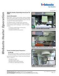
The Webasto <strong>Thermo</strong> <strong>Top</strong> C <strong>Coolant</strong> <strong>Heater</strong> - Overview<br />
Figure 1. <strong>Thermo</strong> <strong>Top</strong> C <strong>Coolant</strong> <strong>Heater</strong><br />
Webasto Product N.A., Inc. 4 www.webasto.us
Webasto TSL 17 <strong>Coolant</strong> <strong>Heater</strong><br />
Operating the Webasto <strong>Coolant</strong> <strong>Heater</strong><br />
Before switching on the Webasto <strong>Thermo</strong> <strong>Top</strong> C, review the following procedures on the proper operating techniques<br />
to ensure a <strong>com</strong>fortable interior. The Webasto can be activated either by a supplied ON / OFF rocker switch, or optional<br />
7 Day Digital Timer.<br />
<strong>Heater</strong> Activation with the Standard Equipped Rocker Switch<br />
Figure 2. Standard Equipped Rocker Switch<br />
The <strong>Thermo</strong> <strong>Top</strong> C heater is activated by depressing the rocker switch to the ‘ON’ position. Once switched on, the<br />
heater begins operation and shortly thereafter, heated coolant is circulated through the engine’s coolant system.<br />
<strong>Heater</strong> Deactivation<br />
Operating Instructions<br />
ATTENTION<br />
The heater will not operate using the rocker switch unless the vehicle’s ignition key is switched to the<br />
‘ACCESSORIES’ position for preheat (engine not running) or ‘IGNITION’ position (engine running) for boost<br />
heating.<br />
Manually:<br />
By returning the rocker switch to the ‘OFF’ position or, if the optional timer is installed, by pressing the “<strong>Heater</strong> On/Off<br />
Button” on the timer (see timer operating instructions on next page). The heater can be switched off at any time<br />
during operation.<br />
Automatically:<br />
Whenever the ignition key is switched off, the heater will also shut-down. If the optional timer is installed, the heater<br />
will be switched off automatically once the timer reaches the end of a timed cycle (preheat mode) or whenever the<br />
ignition is switched off while the heater is running (boost heat mode).<br />
In all cases, whenever the heater is turned off, it will immediately begin a brief cool-down period. The cool-down<br />
period allows the heater to burn off any residual fuel and purge the <strong>com</strong>bustion chamber with cool air.<br />
ATTENTION<br />
The heater will automatically shut-down anytime the ignition key is switched to the ‘OFF’ position. This<br />
prevents the heater from being unintentionally left on for extended periods and possibly discharging the<br />
vehicle batteries.<br />
WARNING!<br />
To avoid the possibility of fire or explosion causing injury or death, the Webasto heater MUST be<br />
switched off before entering fueling stations, during refueling or entering areas where flammable or<br />
explosive materials, gases, fumes or dusts are present.<br />
www.webasto.us 5 Webasto Product N.A., Inc.
Operating Instructions<br />
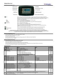
Operating the <strong>Coolant</strong> <strong>Heater</strong> with the OPTIONAL 7-Day Digital Timer<br />
1<br />
2<br />
3<br />
1<br />
2<br />
1<br />
2<br />
3<br />
1<br />
2<br />
Timer Memory Selection<br />
Number<br />
Clock Button<br />
Program<br />
Selection<br />
Button<br />
Day of<br />
the Week<br />
Time of Day<br />
and Timer Display<br />
<strong>Heater</strong><br />
On/Off<br />
Button<br />
Setting the Time and Day of the Week<br />
Press and hold for 2 seconds. Time of day will start flashing.<br />
Webasto TSL 17 <strong>Coolant</strong> <strong>Heater</strong><br />
Day/Time<br />
Reverse<br />
Button<br />
Press Or to adjust time setting. Once time is set, release button.<br />
Flashing will stop after 5 seconds and day of the week will begin flashing.<br />
Press Or to select the day of the week. Once set, wait for flashing to stop.<br />
Operating the <strong>Heater</strong> in Manual Mode<br />
Press to activate the heater. The operation indicator will light up.<br />
Press to deactivate the heater. The operation indicator will go out.<br />
Programming <strong>Heater</strong> Starting Times<br />
Press to begin timer programming. The timer memory selection number starts flashing.<br />
Continue to press button until the desired memory selection number (1, 2 or 3) is visible.<br />
Press Or to adjust heater start time setting. Once start time is set, release button.<br />
Flashing will stop after 5 seconds and day of the week will begin flashing.<br />
Press Or to select day of the week. Once set, wait for flashing to stop.<br />
The heater will start on the time and day selected. To program the other two<br />
memory locations, repeat the above 3 steps for each location.<br />
Recalling or Cancelling a Programmed Starting Times<br />
On/Off<br />
Operation<br />
Indicator<br />
Day/Time<br />
Forward<br />
Button<br />
Press to cycle through the selection numbers. Any one of the three memory numbers can be activated<br />
each time the button is pressed.<br />
After selecting the memory number you desire, you can recall or change the day and time setting<br />
if desired be repeating steps 1, 2 and 3 under “Programming <strong>Heater</strong> Starting Times”.<br />
Press repeatedly until no memory location number is visible on the timer display.<br />
Webasto Product N.A., Inc. 6 www.webasto.us
Webasto TSL 17 <strong>Coolant</strong> <strong>Heater</strong><br />
Startup Sequence / Preheat Sequence with OPTIONAL Timer<br />
To further ensure a warm and <strong>com</strong>fortable interior temperature, the following preheating and operational sequence is<br />
re<strong>com</strong>mended:<br />
1. Preheat the vehicles engine using ONLY the Webasto heater (Engine Off).<br />
2. Start the vehicles engine.<br />
DO NOT leave engine idling with all heater fans in the ‘ON’ position. Doing so will decrease the<br />
amount of heat available.<br />
3. Start the driving route, leaving the Webasto heater in the ‘ON’ position.<br />
Operating Instructions<br />
ATTENTION<br />
The Webasto heater has a start up and shut down procedure that takes several minutes to <strong>com</strong>plete.<br />
Repeatedly turning the Webasto heater on and off will result in a malfunction, and can potentially damage<br />
the heater.<br />
www.webasto.us 7 Webasto Product N.A., Inc.
Technical Data<br />
Technical Data and Information<br />
Webasto TSL 17 <strong>Coolant</strong> <strong>Heater</strong><br />
Unless tolerances are shown within the technical data table, a tolerance of ± 10% applies at an ambient temperature<br />
of +20 °C (+68 °F) and at the rated voltage and conditions.<br />
Table 1: Technical Data<br />
<strong>Heater</strong> <strong>Thermo</strong> <strong>Top</strong> C<br />
Mark of Approval: ~S 289<br />
Design Type: <strong>Coolant</strong> heater with evaporator burner (Ferro-Tech Technology)<br />
Heat Output Rating:<br />
- full load<br />
- part load<br />
5.0 kW (17,076 Btu/hr)<br />
2.5 kW (8,538 Btu/hr)<br />
Fuel<br />
Fuel Consumption:<br />
Diesel #1 Diesel #2 Arctic and Kerosene<br />
- full load<br />
0.59 l/hr (0.155 US gal/hr)<br />
- part load<br />
0.30 l/hr (0.079 US gal/hr)<br />
Rated Voltage: 12 Volts<br />
Operating Voltage Range:<br />
Rated Power Consumption Without<br />
Circulating Pump:<br />
10.5... 15 Volts<br />
- full load<br />
26 Watts (2.1 Amps)<br />
- part load<br />
Maximum Permissible Ambient Temperature:<br />
18 Watts (1.5 Amps)<br />
<strong>Heater</strong>: - operation<br />
-40°... + 60°C (-40°... +140°F)<br />
- storage<br />
-40°... +120°C (-40°... +248°F)<br />
Metering Pump: - operation<br />
-40°... + 20°C (-40°... +68°F)<br />
Maximum Allowable Working Pressure<br />
(<strong>Coolant</strong> System): 0.4... 2.5 Bar (5.8... 36 PSI)<br />
Capacity of Heat Exchanger: 0.15 Liters (0.039 US gallons)<br />
Min. Capacity of <strong>Coolant</strong> System: 4.0 Liters (1.0 US gallons)<br />
Min. Volume of Flow: 250 l/hr (66 US gal/hr)<br />
CO2 Content in Exhaust Gas<br />
(operating range maximum)<br />
8... 12.0 Vol.-%<br />
Dimensions of <strong>Heater</strong> Length 214 mm (8.42 in.)<br />
Width 106 mm (4.17 in.)<br />
Height 168 mm (6.61 in.)<br />
Weight of <strong>Heater</strong> 2.9 kg (6.3 lb.)<br />
Circulating Pump Model U 4847<br />
Volume Flow Against 0.1 Bar (1.45 PSI): 900 l/hr (237.75 gal/hr)<br />
Rated Voltage: 12 Volts<br />
Operating Voltage Range: 10.5... 15 Volts<br />
Rated Power Consumption 14 Watts (1.16 Amps)<br />
Dimensions of Circulating Pump: L 95 mm X W 61 mm X H 61 mm (3.74 in. X 2.4 in. X 2.4 in.)<br />
Weight of <strong>Heater</strong> 0.3 kg (0.66 lb.)<br />
Webasto Product N.A., Inc. 8 www.webasto.us
Webasto TSL 17 <strong>Coolant</strong> <strong>Heater</strong><br />
Electrical Components<br />
Control unit, fan motor, fuel metering pump, digital timer and pencil-type glow pin are designed for 12-volt operation.<br />
The temperature limiter and flame detector are voltage-independent <strong>com</strong>ponents<br />
Fuel Requirements<br />
The Diesel fuel re<strong>com</strong>mended for use by the vehicle manufacturer is suitable as fuel for the heater. When changing to<br />
cold-resistant fuels, the heater must be operated for approximately 15 minutes to ensure that the fuel line and the fuel<br />
pump are also filled with the new type of fuel.<br />
Any negative effect caused by fuel additives is not known. The addition of waste oil is not permitted.<br />
Dimensions<br />
Figure 3. <strong>Heater</strong> Dimensions<br />
40 mm<br />
(1.57 in.)<br />
Figure 4. Fuel Pump Dimensions<br />
137 mm (5.39 in.)<br />
Technical Data<br />
ATTENTION<br />
The fuel pump must be<br />
mounted horizontally (level)<br />
to operate properly.<br />
www.webasto.us 9 Webasto Product N.A., Inc.
Technical Data<br />
Functional Description<br />
Switch ON<br />
Webasto TSL 17 <strong>Coolant</strong> <strong>Heater</strong><br />
Upon switching the heater on by the rocker switch or the optional timer, the ceramic igniter pin, the <strong>com</strong>bustion air fan<br />
and the circulation pump are activated. After 30 seconds the fuel metering (dosing) pump starts operation and<br />
<strong>com</strong>bustion air fan operation is suspended for 3 seconds.<br />
Subsequently the <strong>com</strong>bustion air fan speed is increased in two ramps within 56 seconds to nearly full load operation.<br />
After a stabilization phase (constant speed) of 15 seconds the <strong>com</strong>bustion air fan speed is again increased in a ramp<br />
within 50 seconds to nearly full load.<br />
After reaching full load fuel delivery, the ceramic igniter pin is deactivated and the <strong>com</strong>bustion air fan operation is<br />
increased to full load.<br />
During the subsequent 45 seconds as well as in normal operation the ceramic igniter pin functions as a flame sensor to<br />
monitor the flame condition.<br />
Once all these events are <strong>com</strong>pleted, the heater begins the automatically controlled heating period of operation.<br />
In case of a no flame condition or a flameout, a restart is automatically initiated. If the no flame condition persists, fuel<br />
delivery is stopped and the heater enters an error lockout with a cool-down of the <strong>com</strong>bustion air fan.<br />
A flameout during normal <strong>com</strong>bustion operation causes an automatic restart.<br />
Heating Operation<br />
When the temperature rises to reach 161° F (72° C) the heater switches to the energy saving part load operation.<br />
A further rise in temperature up to 171° F (77° C) causes the heater to enter a control idle period. This also happens<br />
when exceeding a total heating operating time of 76 minutes.<br />
The circulation pump and the operation indicator light (if equipped) remain on during control idle.<br />
After cool-down of the coolant to 160° F (71° C) the heater resumes part load operation. Another rise in temperature<br />
to 171° F (77° C) causes the heater to enter again the control idle period. A drop in the coolant temperature during<br />
part load operation due to an increased demand in heat will cause the heater to switch to full load operation at 133° F<br />
(56° C).<br />
Should the coolant temperature however not drop within 15 minutes during the control idle period to below 160° F<br />
(71° C), a subsequent drop in the coolant temperature below 160° F (71° C) causes the heater to perform a regular<br />
starting sequence into full load operation.<br />
Switch Off<br />
When turning the heater off the <strong>com</strong>bustion process terminates and cool-down <strong>com</strong>mences. The circulation pump<br />
and the <strong>com</strong>bustion air fan first continue operation to cool the heater down (cool-down) to be automatically switched<br />
off afterwards.<br />
NOTE<br />
The cool-down time and the <strong>com</strong>bustion air fan speed depend on the heater operating condition at the time of deactivation.<br />
Cool-down time is 175 seconds when deactivated in full load operation and 100 seconds when deactivated in part load operation.<br />
Dependent on the software variant implemented in the control unit there might be deviations from those cool-down periods.<br />
Webasto Product N.A., Inc. 10 www.webasto.us
Webasto TSL 17 <strong>Coolant</strong> <strong>Heater</strong><br />
Annual Maintenance<br />
General Information<br />
The <strong>Thermo</strong> <strong>Top</strong> C coolant heater requires a minimum of maintenance to keep it in good operating condition.<br />
The following maintenance procedures should be performed annually before each heating season:<br />
<strong>Heater</strong><br />
– Clean the heater of any accumulated debris or dust with <strong>com</strong>pressed air.<br />
– Inspect all <strong>com</strong>ponents for wear and damage. Repair or replace worn and damaged <strong>com</strong>ponents.<br />
Electrical System<br />
– Check wiring harnesses for damage, repair or replace damaged wiring.<br />
– Check the condition of the batteries and the connections.<br />
– Load test the batteries and replace if necessary.<br />
Combustion Air System<br />
– Check for obstructions at air intake port.<br />
– Check air intake tube carefully for restrictions and damage. Repair or replace if damaged.<br />
Exhaust System<br />
– Check the exhaust system carefully for restrictions or corrosion. Repair or replace if damaged.<br />
Fuel System<br />
– Change fuel filter once a year preferably before the heating season. Inspect fuel line for damage, restrictions,<br />
routing or loose connections. Repair or replace if damaged.<br />
<strong>Coolant</strong> System<br />
– Inspect all coolant lines and clamps for leakage, restrictions or damage. Repair or replace.<br />
– Inspect coolant circulation pump for leakage. Repair or replace if leaking or damaged.<br />
Operational Test<br />
– Run your heating system for at least 15 minutes.<br />
– Check water and fuel connections for leakage. Re-tighten hose clamps if necessary.<br />
ATTENTION<br />
The heater will not function properly with defective or discharged batteries.<br />
Annual Maintenance<br />
ATTENTION<br />
Operate the Webasto <strong>Thermo</strong> <strong>Top</strong> C coolant heater at least once a month for 20 minutes to keep it in<br />
optimal operating condition.<br />
www.webasto.us 11 Webasto Product N.A., Inc.
Basic Troubleshooting<br />
Basic Troubleshooting<br />
General Information<br />
Webasto TSL 17 <strong>Coolant</strong> <strong>Heater</strong><br />
This section describes basic troubleshooting procedures for the <strong>Thermo</strong> <strong>Top</strong> C coolant heater. Troubleshooting is<br />
normally limited to the isolation of defective <strong>com</strong>ponents. For more in depth troubleshooting, servicing and repair of<br />
the heater, refer to the Workshop Handbook available from Webasto Product N.A., Inc.<br />
CAUTION!<br />
Troubleshooting requires profound knowledge about structure and theory of operation of the heater<br />
<strong>com</strong>ponents and should only be performed by trained personnel familiar with Webasto heating systems.<br />
Before troubleshooting, check for and eliminate the following for possible causes of a malfunction:<br />
blown fuses<br />
fuel supply (plugged fuel filter)<br />
corroded battery terminals, electrical wiring, connections and fuses<br />
loose contacts at connections and connectors<br />
shut-down initiated by temperature limiter<br />
NOTE<br />
After any correction of a malfunction, a functional test has to be performed with the heater normally installed in the vehicle.<br />
General Malfunction Table<br />
The following table lists possible malfunctions, probable causes and remedies.<br />
Malfunction Probable Cause Remedy<br />
<strong>Coolant</strong> heater switches<br />
off unexpectedly<br />
(Fault lockout)<br />
<strong>Heater</strong> expels black<br />
smoke from exhaust<br />
No <strong>com</strong>bustion after start<br />
or automatic restart<br />
Flame extinguishes during<br />
operation<br />
<strong>Heater</strong> overheats<br />
Vehicle electrical system<br />
voltage too low<br />
Combustion air and/or<br />
exhaust tubing blocked<br />
Switch off heater momentarily and switch on once again<br />
Switch off heater momentarily and switch on once again<br />
Check for closed coolant circuit valves, obstructed coolant<br />
lines. Check coolant level. Allow heater to cool down.<br />
Switch off heater momentarily and switch on once again.<br />
Should heater fail to activate, see “<strong>Heater</strong> Lockout Reset<br />
Procedure” on following page.<br />
Charge battery<br />
Switch off heater momentarily and switch on once again<br />
Check <strong>com</strong>bustion and exhaust tubing for obstructions and<br />
clear<br />
Webasto Product N.A., Inc. 12 www.webasto.us
Webasto TSL 17 <strong>Coolant</strong> <strong>Heater</strong><br />
<strong>Heater</strong> Lockout Reset Procedure<br />
The Webasto <strong>Thermo</strong> <strong>Top</strong> C coolant heater is designed with a lockout safety feature built into the control unit. After 3<br />
consecutive unsuccessful startup attempts, the heater will lock itself out from any further start attempts. The heater<br />
may also enter the lockout mode after experiencing an overheat condition.<br />
1. Ensure switch or optional timer is in the “OFF” position. Turn switch or timer to the “On” position. Remove main<br />
fuse F1 (20 Amp), reinsert after 5 seconds.<br />
2. Cycle switch or timer off and then back on once more. Remove fuse F1 once again and reinsert after 5 seconds.<br />
<strong>Heater</strong> should attempt to start after inserting fuse.<br />
NOTE<br />
<strong>Coolant</strong> temperature must be below the lower threshold before heater will attempt to start.<br />
PC Diagnostics Kit<br />
Basic Troubleshooting<br />
It is possible to read and remove (reset) stored malfunction codes from the <strong>Thermo</strong> <strong>Top</strong> C’s internal memory.<br />
This is achieved through the use of a diagnostic interface kit connected to the <strong>Thermo</strong> <strong>Top</strong> C and a PC <strong>com</strong>puter with<br />
Microsoft Windows operating system and the PC Diagnostic software loaded.<br />
The PC Diagnostic Interface Kit <strong>com</strong>es <strong>com</strong>plete with connecting hardware including software and user’s guide on<br />
<strong>com</strong>pact disc. Order PC Diagnostics Kit under part number 1301728B.<br />
Kit includes the required adapter for the <strong>Thermo</strong> <strong>Top</strong> C/Z and Air <strong>Top</strong> 2000 heaters. More adapters are available for<br />
other Webasto heaters with internal diagnostic capabilities.<br />
In addition to working with stored malfunction codes, the PC Diagnostics Kit allows you to do several other functions<br />
such as reading values while the heater is in operation or testing individual <strong>com</strong>ponents.<br />
Print out capability of malfunction codes and heater data is also provided (user supplied printer required).<br />
For further capabilities and instructions for use with the <strong>Thermo</strong> <strong>Top</strong> C heater, refer to the user’s guide on <strong>com</strong>pact disc<br />
supplied with the PC Diagnostics Kit.<br />
www.webasto.us 13 Webasto Product N.A., Inc.
Schematics<br />
Figure 5.<br />
Webasto TSL 17 <strong>Coolant</strong> <strong>Heater</strong><br />
X2 Connector 2–Way<br />
X3 Connector 2–Way<br />
X4 Connector 2–Way<br />
X5 Connector 2–Way<br />
X6 Connector 3–Way<br />
X7 Connector 2–Way<br />
B2 Temperature Sensor<br />
E Ceramic Igniter/Flame Sensor<br />
F1 20A Fuse<br />
F2 2A Fuse<br />
M1 Combustion Air Fan<br />
M2 <strong>Coolant</strong> Circulation Pump<br />
X1 Connector 6–Way<br />
Webasto Product N.A., Inc. 14 www.webasto.us
Webasto TSL 17 <strong>Coolant</strong> <strong>Heater</strong><br />
Figure 6.<br />
Service Parts Listing<br />
X2 Connector 2–Way<br />
X3 Connector 2–Way<br />
X4 Connector 2–Way<br />
X5 Connector 2–Way<br />
X6 Connector 3–Way<br />
X7 Connector 2–Way<br />
B2 Temperature Sensor<br />
E Ceramic Igniter/Flame Sensor<br />
F1 20A Fuse<br />
F2 2A Fuse<br />
M1 Combustion Air Fan<br />
M2 <strong>Coolant</strong> Circulation Pump<br />
X1 Connector 6–Way<br />
www.webasto.us 15 Webasto Product N.A., Inc.
Webasto TSL 17<br />
Table des matières Page<br />
Avant-propos 19<br />
Renseignements généraux . . . . . . . . . . . . . . . . . . . . . . . . . . . . . . . . . . . . . . . . . . . . . . . . . . . . . . . . . . . . . . . . . . . . . . . . . 19<br />
Renseignements et symboles de sécurité et leurs significations . . . . . . . . . . . . . . . . . . . . . . . . . . . . . . . . . . . . . . . . . . . . . . 19<br />
Renseignements sur l’entretien et la sécurité, à lire avant d’utiliser le réchauffeur <strong>Thermo</strong> <strong>Top</strong> C . . . . . . . . . . . . . . . . . . . . . 19<br />
Vue d’ensemble du réchauffeur Webasto <strong>Thermo</strong> <strong>Top</strong> C . . . . . . . . . . . . . . . . . . . . . . . . . . . . . . . . . . . . . . . . . . . . . . . . . . 20<br />
Consignes d’utilisation 21<br />
Utilisation du réchauffeur de liquide de refroidissement Webasto . . . . . . . . . . . . . . . . . . . . . . . . . . . . . . . . . . . . . . . . . . . . 21<br />
Mise en marche du réchauffeur à l’aide du <strong>com</strong>mutateur à bascule livré de série. . . . . . . . . . . . . . . . . . . . . . . . . . . . . . . 21<br />
Arrêt du réchauffeur . . . . . . . . . . . . . . . . . . . . . . . . . . . . . . . . . . . . . . . . . . . . . . . . . . . . . . . . . . . . . . . . . . . . . . . . . . . . 21<br />
Utilisation du réchauffeur équipé de la minuterie numérique de 7 jours . . . . . . . . . . . . . . . . . . . . . . . . . . . . . . . . . . . . . . . 22<br />
Séquence de la mise en marche/séquence de réchauffage avec minuterie OPTIONNELLE . . . . . . . . . . . . . . . . . . . . . . . . . . . 23<br />
Spécifications techniques 24<br />
Renseignements et spécifications techniques. . . . . . . . . . . . . . . . . . . . . . . . . . . . . . . . . . . . . . . . . . . . . . . . . . . . . . . . . . . . 24<br />
Composants électriques . . . . . . . . . . . . . . . . . . . . . . . . . . . . . . . . . . . . . . . . . . . . . . . . . . . . . . . . . . . . . . . . . . . . . . . . . . . 25<br />
Propriétés du carburant. . . . . . . . . . . . . . . . . . . . . . . . . . . . . . . . . . . . . . . . . . . . . . . . . . . . . . . . . . . . . . . . . . . . . . . . . . . . 25<br />
Dimensions. . . . . . . . . . . . . . . . . . . . . . . . . . . . . . . . . . . . . . . . . . . . . . . . . . . . . . . . . . . . . . . . . . . . . . . . . . . . . . . . . . . . . 25<br />
Description du fonctionnement. . . . . . . . . . . . . . . . . . . . . . . . . . . . . . . . . . . . . . . . . . . . . . . . . . . . . . . . . . . . . . . . . . . . . . 26<br />
Commutateur à la position marche . . . . . . . . . . . . . . . . . . . . . . . . . . . . . . . . . . . . . . . . . . . . . . . . . . . . . . . . . . . . . . . . . 26<br />
Fonctionnement du système de réchauffage . . . . . . . . . . . . . . . . . . . . . . . . . . . . . . . . . . . . . . . . . . . . . . . . . . . . . . . . . . 26<br />
Commutateur à la position arrêt . . . . . . . . . . . . . . . . . . . . . . . . . . . . . . . . . . . . . . . . . . . . . . . . . . . . . . . . . . . . . . . . . . . 26<br />
Entretien annuel 27<br />
Renseignements généraux . . . . . . . . . . . . . . . . . . . . . . . . . . . . . . . . . . . . . . . . . . . . . . . . . . . . . . . . . . . . . . . . . . . . . . . . . 27<br />
Réchauffeur . . . . . . . . . . . . . . . . . . . . . . . . . . . . . . . . . . . . . . . . . . . . . . . . . . . . . . . . . . . . . . . . . . . . . . . . . . . . . . . . . . . . 27<br />
Système électrique . . . . . . . . . . . . . . . . . . . . . . . . . . . . . . . . . . . . . . . . . . . . . . . . . . . . . . . . . . . . . . . . . . . . . . . . . . . . . . . 27<br />
Système d’air <strong>com</strong>burant . . . . . . . . . . . . . . . . . . . . . . . . . . . . . . . . . . . . . . . . . . . . . . . . . . . . . . . . . . . . . . . . . . . . . . . . . . 27<br />
Système d’échappement. . . . . . . . . . . . . . . . . . . . . . . . . . . . . . . . . . . . . . . . . . . . . . . . . . . . . . . . . . . . . . . . . . . . . . . . . . . 27<br />
Circuit d’alimentation en carburant. . . . . . . . . . . . . . . . . . . . . . . . . . . . . . . . . . . . . . . . . . . . . . . . . . . . . . . . . . . . . . . . . . . 27<br />
Système de refroidissement. . . . . . . . . . . . . . . . . . . . . . . . . . . . . . . . . . . . . . . . . . . . . . . . . . . . . . . . . . . . . . . . . . . . . . . . . 27<br />
Essai de fonctionnement. . . . . . . . . . . . . . . . . . . . . . . . . . . . . . . . . . . . . . . . . . . . . . . . . . . . . . . . . . . . . . . . . . . . . . . . . . . 27<br />
Dépannage de base 28<br />
Renseignements généraux . . . . . . . . . . . . . . . . . . . . . . . . . . . . . . . . . . . . . . . . . . . . . . . . . . . . . . . . . . . . . . . . . . . . . . . . . 28<br />
Tableau général des dysfonctionnements . . . . . . . . . . . . . . . . . . . . . . . . . . . . . . . . . . . . . . . . . . . . . . . . . . . . . . . . . . . . . . 28<br />
Modalité de réinitialisation du dispositif de verrouillage du réchauffeur . . . . . . . . . . . . . . . . . . . . . . . . . . . . . . . . . . . . . . . . 29<br />
Trousse de diagnostic pour ordinateur personnel. . . . . . . . . . . . . . . . . . . . . . . . . . . . . . . . . . . . . . . . . . . . . . . . . . . . . . . . . 29<br />
Schémas 30<br />
Schéma de câblage – <strong>com</strong>mutateur marche/arrêt . . . . . . . . . . . . . . . . . . . . . . . . . . . . . . . . . . . . . . . . . . . . . . . . . . . . . . . . 30<br />
Schéma de câblage – minuterie optionnelle 1529 . . . . . . . . . . . . . . . . . . . . . . . . . . . . . . . . . . . . . . . . . . . . . . . . . . . . . . . . 31<br />
Liste des pièces d’entretien 32<br />
www.webasto.us 17 Webasto Product N.A., Inc.
Webasto TSL 17<br />
Webasto Product N.A., Inc. 18 www.webasto.us
Webasto TSL 17<br />
Foreword<br />
General Information<br />
Aux clients de Webasto,<br />
Nous prenons pour acquis que l’atelier ou le centre de service qui a procédé à l’installation de votre réchauffeur<br />
Webasto vous en a expliqué le mode d’exploitation et les principes de fonctionnement de façon satisfaisante. Les<br />
consignes d’utilisation contenues dans ce manuel vous donnent une vue d’ensemble du fonctionnement de votre<br />
réchauffeur <strong>Thermo</strong> <strong>Top</strong> C.<br />
Renseignements et symboles de sécurité et leurs significations<br />
Avant-propos<br />
PRUDENCE!<br />
Ce symbole rappelle à l’utilisateur que la non conformité aux consignes et modalités d’exploitation peut<br />
entraîner des blessures sérieuses ou la mort.<br />
PRUDENCE!<br />
Ce symbole rappelle à l’utilisateur que la non conformité aux consignes et modalités d’exploitation peut<br />
causer des dommages au matériel.<br />
ATTENTION<br />
Ce symbole est employé pour mettre en évidence et signaler certains renseignements importants.<br />
Renseignements sur l’entretien et la sécurité, à lire avant d’utiliser le réchauffeur <strong>Thermo</strong> <strong>Top</strong> C!<br />
Le <strong>com</strong>mutateur doit être placé à la position arrêt:<br />
Avant de pénétrer dans un poste d’essence et un dépôt de carburant.<br />
Avant de pénétrer dans un endroit où des vapeurs et des poussières inflammables<br />
peuvent s’accumuler (ex.: près des dépôts de carburant, de charbon de sciure de bois ou<br />
de grain). Il ne faut pas utiliser le réchauffeur sur des surfaces de gazon sec et autres<br />
Danger d'explosion surfaces sèches.<br />
et d’ asphyxie<br />
Avant de pénétrer dans un endroit fermé, entre autres dans un garage. Il importe de tenir<br />
<strong>com</strong>pte de telles précautions lors du réglage des périodes de fonctionnement du<br />
réchauffeur au moyen de la minuterie.<br />
Le réchauffeur ne doit pas être:<br />
Exposé à des températures supérieures à 120C (température d’entreposage). Une telle<br />
exposition peut endommager les <strong>com</strong>posants électroniques.<br />
Utilisé en deçà d’un niveau minimal de 20% d’antigel de bonne qualité dans l’eau du<br />
circuit de chauffage.<br />
www.webasto.us 19 Webasto Product N.A., Inc.
Avant-propos<br />
Renseignements sur l’entretien et la sécurité - suite<br />
Le réchauffeur doit être:<br />
Utilisé en se servant du carburant spécifié sur la plaque signalétique.<br />
Webasto TSL 17<br />
Mis hors service en cas d’une accumulation importante de fumée, de bruits de<br />
<strong>com</strong>bustion inhabituels ou d’odeurs de carburant. Pour ce faire, on retire le fusible.<br />
La remise en marche se fait uniquement après que le matériel ait été inspecté par une<br />
personne qualifiée.<br />
Mis en exploitation au moins une fois par mois pendant dix minutes alors que le moteur<br />
est froid. Le réchauffeur doit être vérifié annuellement par un spécialiste qualifié,<br />
préférablement avant que la saison de chauffage ne <strong>com</strong>mence.<br />
Demandes de règlement en responsabilité:<br />
La société Webasto n'assume aucune responsabilité si les consignes d'installation et les<br />
notes de sécurité contenues dans cette publication ne sont pas observées. La même<br />
dénégation de responsabilité s'applique si les réparations sont mal exécutées ou si les<br />
pièces utilisées ne sont pas des pièces de rechange d'origine. Dans ces cas, la certification<br />
des caractéristiques de fabrication générales sont nulles et non avenues.<br />
Les demandes de règlement ne sont respectées que si le demandeur peut prouver que les<br />
consignes et les notes de sécurité ont été observées.<br />
Vue d’ensemble du réchauffeur de liquide de refroidissement Webasto <strong>Thermo</strong> <strong>Top</strong> C<br />
Ensemble du ventilateur d’air <strong>com</strong>burant<br />
Pompe de circulation du<br />
liquide de refroidissement<br />
Module de <strong>com</strong>mande/<br />
Échangeur de chaleur<br />
Chambre de <strong>com</strong>bustion<br />
Figure 1. Réchauffeur de liquide de refroidissement <strong>Thermo</strong> <strong>Top</strong> C<br />
Webasto Product N.A., Inc. 20 www.webasto.us
Webasto TSL 17<br />
Utilisation du réchauffeur de liquide de refroidissement Webasto<br />
Avant de mettre en marche le réchauffeur Webasto <strong>Thermo</strong> <strong>Top</strong> C, passer en revue les consignes suivantes sur les<br />
techniques d’utilisation appropriées aux fins d’un confort intérieur maximal. Le réchauffeur Webasto peut être mis en<br />
marche au moyen du <strong>com</strong>mutateur à bascule MARCHE/ARRÊT livré de série ou de la minuterie numérique de 7 jours<br />
livrée sur option.<br />
Mise en marche du réchauffeur à l’aide du <strong>com</strong>mutateur à bascule livré de série<br />
Le réchauffeur RSL 17 est mis en marche en plaçant le <strong>com</strong>mutateur à bascule à la position marche.<br />
Une fois à cette position, le réchauffeur <strong>com</strong>mence à fonctionner et peu de temps après le liquide de<br />
refroidissement réchauffé circule dans le système de refroidissement du moteur.<br />
Figure 2. Commutateur à bascule livré de série<br />
ATTENTION<br />
Le réchauffeur ne peut être mis en marche au moyen du <strong>com</strong>mutateur à bascule à moins que la clé de<br />
contact du véhicule ne soit placée à la position ACCESSOIRES pour le réchauffage (moteur arrêté) ou à la<br />
position ALLUMAGE (moteur en marche) pour le chauffage d’appoint.<br />
Arrêt du réchauffeur<br />
Consignes d'utilisation<br />
Mode manuel:<br />
Replacer le <strong>com</strong>mutateur à bascule à la position arrêt ou, si l’appareil est pourvu de la minuterie optionnelle, presser sur<br />
le bouton marche/arrêt de la minuterie (se reporter aux consignes d’utilisation de la minuterie à la page suivante). Il est<br />
possible de fermer le réchauffeur en tout temps pendant qu’il est en cours de fonctionnement.<br />
Mode automatique:<br />
Dès que la clé de contact est placée en position arrêt, le réchauffeur s’arrête immédiatement. Si l’appareil est doté<br />
d’une minuterie optionnelle, le réchauffeur s’arrête automatiquement dès que celle-ci <strong>com</strong>plète son cycle de<br />
fonctionnement chronométré (mode de réchauffage) ou dès que la clé de contact est placée à la position arrêt alors<br />
que le réchauffeur fonctionne (mode de chauffage d’appoint).<br />
Dans tous les cas, dès que réchauffeur est arrêté, il amorce immédiatement une brève période de refroidissement. La<br />
période de refroidissement permet au réchauffeur de brûler le carburant résiduel et de purger la chambre de<br />
<strong>com</strong>bustion avec l’apport d’air frais.<br />
ATTENTION<br />
Le réchauffeur s’arrête automatiquement dès que la clé de contact est placée à la position arrêt. Cette<br />
caractéristique fonctionnelle prévient les longues périodes de fonctionnement fortuites et le<br />
déchargement possible des batteries.<br />
AVERTISSEMENT!<br />
Pour éviter les risques d’incendie ou d’explosion susceptibles de causer des blessures ou la mort, le<br />
réchauffeur Webasto DOIT être mis hors service avant de pénétrer dans les postes d’essence, de faire le<br />
plein d’essence et de pénétrer dans les endroits où se trouvent des poussières, des fumées, des<br />
matériaux ou des gaz inflammables.<br />
www.webasto.us 21 Webasto Product N.A., Inc.
Consignes d'utilisation<br />
Utilisation du réchauffeur équipé de la minuterie numérique de 7 jours<br />
Sélection des nombres<br />
mémorisés par la minuterie<br />
1<br />
2<br />
3<br />
1<br />
2<br />
1<br />
2<br />
3<br />
Bouton de l’horloge<br />
Bouton de<br />
sélection du<br />
programme<br />
Jour de la<br />
semaine<br />
Heure du jour et affichage<br />
de la minuterie<br />
Réchauffeur<br />
Bouton<br />
arrêt/marche<br />
Réglage de l’heure et du jour de la semaine<br />
Appuyer sur et maintenir 2 secondes. L’heure du jour clignote.<br />
Jour/heure<br />
Bouton vers<br />
l'arrière<br />
Webasto TSL 17<br />
Appuyer sur ou pour mettre au point le réglage de l’heure. Une fois la mise au point terminée,<br />
relâcher le bouton.<br />
Le clignotement cesse après 5 secondes et le jour de la semaine se met à son tour<br />
à clignoter.<br />
Appuyer sur ou pour sélectionner le jour de la semaine. Une fois la sélection faite, attendre que le<br />
clignotement cesse.<br />
Mode de fonctionnement manuel du réchauffeur<br />
Appuyer sur et mettre en marche le réchauffeur. L’indicateur de fonctionnement s’allume.<br />
Appuyer sur pour arrêter le réchauffeur. L’indicateur de fonctionnement s’éteint.<br />
Programmation des heures de mise en marche du réchauffeur<br />
Indicateur de<br />
fonctionnement<br />
marche/arrêt<br />
Jour/heure<br />
Bouton vers<br />
l'avant<br />
Appuyer sur pour amorcer la programmation de la minuterie. Le numéro de sélection de mémorisation<br />
inscrit dans la minuterie se met à clignoter.<br />
Garder le bouton en position enfoncée jusqu’à ce que le numéro de sélection de<br />
mémorisation désiré (1, 2 ou 3) soit visible.<br />
Appuyer sur ou pour mettre au point l’heure de mise en marche du réchauffeur. Une fois l’heure<br />
de mise en marche réglée, relâcher le bouton.<br />
Le clignotement cesse après 5 secondes et le jour de la semaine se met à son tour<br />
à clignoter.<br />
Appuyer sur ou pour sélectionner le jour de la semaine. Le réchauffeur se met en marche à<br />
l’heure et au jour sélectionnés. Pour programmer les deux autres sélections de<br />
mémorisation, répéter les trois étapes précédentes pour chacune des sélections.<br />
Webasto Product N.A., Inc. 22 www.webasto.us
Webasto TSL 17<br />
1<br />
2<br />
Rappel et annulation des heures de mise en marche programmées<br />
Séquence de mise en marche/séquence de réchauffage avec minuterie OPTIONNELLE<br />
De manière à maintenir une température chaude et confortable dans la cabine, il importe de se conformer à la<br />
séquence de fonctionnement et de réchauffage suivante:<br />
1. Réchauffer le moteur du véhicule en utilisant UNIQUEMENT le réchauffeur Webasto (le moteur étant<br />
arrêté).<br />
2. Démarrer le moteur du véhicule.<br />
NE PAS laisser tourner le moteur au ralenti alors que tous les ventilateurs du réchauffeur sont à la<br />
position MARCHE. En ce faisant, on réduit la quantité de chaleur disponible.<br />
3. Amorcer votre voyage en laissant le réchauffeur Webasto à la position MARCHE.<br />
Operating Instructions<br />
Appuyer sur pour passer en revue les numéros de sélection. L’un quelconque des trois numéros de<br />
mémorisation peut être sollicité en appuyant sur le bouton.<br />
Une fois le numéro de mémorisation désiré sélectionné, rappeler ou modifier les réglages du jour ou de<br />
l’heure si nécessaire en répétant les étapes 1, 2 et 3 de la section « Programmation des heures de mise en<br />
marche du réchauffeur ».<br />
Appuyer sur de façon itérative jusqu’à ce qu’aucun numéro de sélection de mémorisation ne soit visible<br />
sur l’affichage de la minuterie.<br />
ATTENTION<br />
Les modalités de mise en marche et d’arrêt du réchauffeur Webasto s’échelonnent sur plusieurs minutes.<br />
Le réglage répétitif du réchauffeur Webasto aux positions arrêt et marche peut entraîner le mauvais<br />
fonctionnement de l’appareil et peut endommager celui-ci.<br />
www.webasto.us 23 Webasto Product N.A., Inc.
Spécifications techniques<br />
Renseignements et spécifications techniques<br />
Webasto TSL 17<br />
À moins que les tolérances ne soient indiquées dans le tableau des spécifications techniques, un écart de +/- 10%<br />
s’applique à une température ambiante de +20 ºC (68 ºF) et à la tension et aux conditions nominales.<br />
Réchauffeur Modèle <strong>Thermo</strong> <strong>Top</strong> C<br />
Marque d’homologation ~S 289<br />
Type de modèle Réchauffeur de liquide de refroidissement avec brûleur à évaporateur<br />
(technologie Ferro-Tech)<br />
Puissance calorifique nominale:<br />
- pleine charge<br />
- charge partielle<br />
Tableau 1: spécifications techniques<br />
5,0 kW (17,076 Btu/h)<br />
2,5 kW (8,538 Btu/h)<br />
Carburant Diesel nº 1 et diesel nº 2, Arctique et Kérosène<br />
Consommation de carburant:<br />
- pleine charge<br />
- charge partielle<br />
0,59 l/h (0,155 gal US/h)<br />
0,30 l/h (0,079 gal US/h)<br />
Tension nominale 12 volts<br />
Plage des tensions de fonctionnement<br />
Consommation énergétique nominale sans la<br />
pompe de circulation:<br />
10,5 à 15 volts<br />
pleine charge<br />
26 watts (2,1 A)<br />
charge partielle<br />
Température ambiante maximale autorisée du<br />
18 watts (1,5 A)<br />
brûleur: - en marche<br />
-40º à +60ºC (-40º à +140ºF)<br />
- en entreposage<br />
-40º à +120ºC (-40º à +248ºF)<br />
Pompe de dosage: - en marche<br />
-40º à +20ºC (-40º à +68ºF)<br />
Pression de service maximale autorisée (système<br />
de refroidissement):<br />
0,4 à 2,5 bars (5,8 à 36 lb/po2 )<br />
Capacité de l’échangeur de chaleur 0,15 litres (0,039 gal US)<br />
Capacité minimale du système de<br />
refroidissement:<br />
4,0 litres (1,0 gal US)<br />
Volume d’écoulement minimal 250 l/h (66 gal US/h)<br />
Contenu de CO2 dans les gaz d’échappe-ment<br />
(plage de fonctionnement, max.)<br />
8 à 1,20 vol. -%<br />
Dimensions du réchauffeur Longueur de 235 mm (9,25 po)<br />
Largeur de 104.5 mm (4,11 po)<br />
Hauteur de 162.8 mm (6,40 po)<br />
Poids du réchauffeur 2,9 kg (6,3 lb)<br />
Pompe circulatrice Modèle U 4847<br />
Volume d’écoulement à 0,1 bar (1,45 lb/po2) 900 l/h (237,75 gal/h)<br />
Tension nominale: 12 volts<br />
Plage des tensions de fonctionnement: 10,5 à 15 volts<br />
Consommation énergétique minimale 14 watts (1,16 A)<br />
Dimensions de la pompe circulatrice: Lon. de 95 mm x Lar. de 61 mm x H de 61 mm (3,74 po x 2,4 po x 2,4<br />
po)<br />
Poids de la pompe circulatrice 0,3 kg (0,66 lb)<br />
Webasto Product N.A., Inc. 24 www.webasto.us
Webasto TSL 17<br />
Composants électriques<br />
Le module de <strong>com</strong>mande, le moteur du ventilateur, la pompe de dosage du carburant et la tige à incandescence de<br />
préchauffage sont conçus pour une tension de fonctionnement de 12 volts. Le limiteur de température et l’indicateur<br />
d’extinction ne sont pas affectés par la tension de fonctionnement.<br />
Propriétés du carburant<br />
Le carburant diesel re<strong>com</strong>mandé par le constructeur du camion convient au fonctionnement du réchauffeur. Lors du<br />
passage aux carburants résistant au froid, il est nécessaire de faire fonctionner le réchauffeur pendant environ 15<br />
minutes afin que la canalisation de carburant et la pompe à carburant soient remplies du nouveau type de carburant.<br />
Les effets négatifs engendrés par les additifs ne sont pas connus. L’addition d’huile usagée n’est pas permise.<br />
Dimensions<br />
Figure 3. Dimensions du réchauffeur<br />
40 mm<br />
(1,57 po)<br />
137 mm (5,39 po)<br />
Figure 4. Dimensions de la pompe à carburant<br />
Spécifications techniques<br />
ATTENTION<br />
La pompe à carburant doit<br />
être montée à l’horizontale<br />
(de niveau) pour fonctionner<br />
adéquatement.<br />
www.webasto.us 25 Webasto Product N.A., Inc.
Spécifications techniques<br />
Description du fonctionnement<br />
Commutateur à la position marche<br />
Webasto TSL 17<br />
Quand le réchauffeur est mis en marche au moyen du <strong>com</strong>mutateur à bascule ou de la minuterie optionnelle, la tige<br />
d’allumage en céramique, le ventilateur de l’air <strong>com</strong>burant et la pompe circulatrice sont activés. Après 30 secondes, la<br />
pompe de dosage du carburant entre en fonction et le fonctionnement du ventilateur de l’air <strong>com</strong>burant est suspendu<br />
pendant 3 secondes.<br />
Par la suite, le régime du ventilateur de l’air <strong>com</strong>burant s’accroît en une double accélération d’une durée de 56<br />
secondes pour atteindre pratiquement son stade de fonctionnement en pleine charge. Après une phase de<br />
stabilisation (régime constant) de 15 secondes, le régime du ventilateur de l’air <strong>com</strong>burant s’accroît de nouveau en une<br />
accélération d’une durée de 50 secondes pour atteindre pratiquement son stade de fonctionnement en pleine charge.<br />
Après avoir atteint le niveau d’alimentation en carburant de plein débit, la tige d’allumage en céramique est désactivée<br />
et le régime de fonctionnement du ventilateur de l’air <strong>com</strong>burant grimpe à son niveau optimal.<br />
Durant les 45 secondes suivantes et en cours de fonctionnement normal, la tige d’allumage en céramique agit <strong>com</strong>me<br />
indicateur d’extinction de manière à contrôler la condition de la flamme.<br />
Une fois ces diverses étapes franchies, le réchauffeur amorce la période de fonctionnement à réglage automatique de<br />
la chaleur. En cas d’absence ou d’arrêt de flamme, l’appareil déclenche automatiquement une remise en marche. Si<br />
l’absence de flamme persiste, l’alimentation en carburant est arrêtée et le réchauffeur se place en mode verrouillage,<br />
ce qui donne lieu au refroidissement du ventilateur de l’air <strong>com</strong>burant. L’arrêt de flamme durant une période de<br />
<strong>com</strong>bustion normale donne lieu à une remise en marche automatique.<br />
Fonctionnement du système de réchauffage<br />
Lorsque la température atteint 72º C (161º F), le réchauffeur passe au mode d’économie d’énergie en charge partielle.<br />
Un nouvel accroissement de température jusqu’à 77º C (171º F) fait entrer le réchauffeur dans une période de marche<br />
au ralenti surveillée. Le réchauffeur fait de même lorsque la période de <strong>com</strong>bustion totale dépasse les 76 minutes.<br />
La pompe circulatrice et le voyant de fonctionnement (si installé sur l’appareil) restent en marche durant la période de<br />
marche au ralenti surveillée.<br />
Après le refroidissement du liquide de refroidissement jusqu'à 71º C (160º F), le réchauffeur retourne au mode de<br />
charge partielle. Une nouvelle augmentation de la température jusqu’à 77º C (171º F) retourne le réchauffeur à la<br />
période de marche au ralenti surveillée. Une diminution de la température du liquide de refroidissement durant le<br />
fonctionnement au mode en charge partielle engendrée par une demande accrue de chaleur renvoie le réchauffeur au<br />
mode en pleine charge lorsque la température est de 56º C (133º C).<br />
Si toutefois la température du liquide de refroidissement ne tombe pas à moins de 71º C (160º F) dans les 15 minutes<br />
du fonctionnement au mode de marche au ralenti surveillée, la diminution subséquente de la température du liquide<br />
de refroidissement sous les 71º C (160º F) incite le réchauffeur à exécuter une séquence de démarrage régulière au<br />
mode en pleine charge.<br />
Commutateur à position arrêt<br />
Quand le réchauffeur est placé à la position arrêt, le phénomène de <strong>com</strong>bustion cesse et le refroidissement <strong>com</strong>mence.<br />
La pompe circulatrice et le ventilateur de l’air <strong>com</strong>burant continuent à fonctionner pour refroidir le réchauffeur<br />
(refroidissement) et lui permettre de s’arrêter automatiquement par la suite.<br />
NOTA<br />
La durée du refroidissement et le régime du ventilateur de l’air <strong>com</strong>burant dépendent des conditions d’exploitation du réchauffeur<br />
au moment de désactivation. La durée du refroidissement est de 175 secondes quand la désactivation se fait au mode de<br />
fonctionnement en pleine charge et de 100 secondes quand elle se fait au mode en charge partielle. Selon les variantes du logiciel<br />
implanté dans le module de <strong>com</strong>mande, il peut y avoir des écarts avec les durées de refroidissement indiquées ici.<br />
Webasto Product N.A., Inc. 26 www.webasto.us
Webasto TSL 17<br />
Entretien annuel<br />
Entretien annuel<br />
Renseignements généraux<br />
Un minimum d’entretien est requis pour conserver le réchauffeur de liquide de refroidissement <strong>Thermo</strong> <strong>Top</strong> C dans un<br />
bon état de marche. Les tâches d’entretien suivantes doivent être effectuées annuellement au début de la saison de<br />
chauffage.<br />
Réchauffeur<br />
– Nettoyer le réchauffeur à l’air <strong>com</strong>primé pour chasser la poussière et les débris accumulés<br />
– Inspecter tous les <strong>com</strong>posants pour y découvrir l’usure et les dommages possibles. Réparer ou remplacer les<br />
<strong>com</strong>posants endommagés.<br />
Système électrique<br />
– Vérifier l’état des faisceaux de câbles. Réparer ou remplacer les câbles endommagés.<br />
– Vérifier la condition des batteries et des connecteurs.<br />
– Vérifier la charge des batteries et les remplacer au besoin.<br />
Système d’air <strong>com</strong>burant<br />
– Vérifier l’ouverture d’admission de l’air pour y déloger les obstructions.<br />
– Examiner soigneusement la canalisation d’admission de l’air pour y relever les dommages et chasser les<br />
obstructions. Réparer ou remplacer en cas d’endommagement.<br />
Système d’échappement<br />
– Examiner soigneusement le système d’échappement pour y noter les dommages possibles et la corrosion. Réparer<br />
ou remplacer les <strong>com</strong>posants endommagés.<br />
Circuit d’alimentation en carburant<br />
– Remplacer le filtre à carburant une fois par année, préférablement avant la saison de chauffage. Inspecter la<br />
canalisation de carburant en vue d’y noter les dommages, les obstructions, le routage des câbles et les connexions<br />
lâches. Remplacer ou réparer les pièces en mauvais état.<br />
Système de refroidissement<br />
– Inspecter tous les colliers et les canalisations du système de refroidissement en termes de fuites, d’obstructions et<br />
de dommages. Réparer ou remplacer les <strong>com</strong>posants au besoin.<br />
– Inspecter la pompe circulatrice du liquide de refroidissement sur le plan des fuites. Réparer ou remplacer s’il y a<br />
fuite ou dommage.<br />
Essai de fonctionnement<br />
– Faire fonctionner le système de réchauffage pendant au moins 15 minutes.<br />
– Vérifier les connexions d’eau et de carburant pour y noter les fuites. Resserrer les colliers des canalisations au<br />
besoin.<br />
ATTENTION<br />
Le réchauffeur ne peut fonctionner adéquatement si les batteries sont déchargées ou défectueuses.<br />
ATTENTION<br />
Faire fonctionner le réchauffeur de liquide de refroidissement Webasto <strong>Thermo</strong> <strong>Top</strong> C au moins une fois<br />
par mois pendant 20 minutes pour le conserver en condition de fonctionnement optimale.<br />
www.webasto.us 27 Webasto Product N.A., Inc.
Dépannage de base<br />
Dépannage de base<br />
Renseignements généraux<br />
Webasto TSL 17<br />
La présente section décrit les méthodes de dépannage de base applicables à votre réchauffeur de liquide de<br />
refroidissement <strong>Thermo</strong> <strong>Top</strong> C. Le dépannage se limite normalement à la détermination des <strong>com</strong>posants défectueux.<br />
Pour une recherche des pannes plus approfondie, l’entretien et la réparation de votre réchauffeur, se reporter au<br />
manuel d’atelier distribué par Webasto Product N.A., Inc.<br />
PRUDENCE!<br />
Le dépannage exige une profonde connaissance de la construction et de la théorie de fonctionnement<br />
des <strong>com</strong>posants du réchauffeur. Il importe donc de confier cette tâche uniquement à un personnel<br />
qualifié et familier avec les systèmes de chauffage Webasto.<br />
Avant d’entreprendre la recherche des pannes, vérifier l’appareil afin d’éliminer les causes possibles de mauvais<br />
fonctionnement énumérées ci-après:<br />
Fusibles fondus<br />
Alimentation en carburant (filtre à carburant colmaté)<br />
Bornes de batterie corrodées, câblage électrique, connexions et fusibles<br />
Contacts lâches aux connexions et connecteurs<br />
Mise hors service engendrée par le limiteur de température<br />
NOTA<br />
Une fois le dysfonctionnement corrigé, il convient de faire subir un essai de fonctionnement au réchauffeur installé dans le véhicule.<br />
Tableau général des dysfonctionnements<br />
Le tableau suivant énumère les dysfonctionnements possibles, les causes probables et les mesures correctives à prendre.<br />
Dysfonctionnement Cause probable Mesures correctives<br />
Réchauffeur mis hors Aucune <strong>com</strong>bustion après la Mettre momentanément le réchauffeur hors tension et le<br />
tension soudainement mise en marche ou remise en remettre sous tension une fois encore.<br />
(verrouillage défaillant) marche automatique<br />
Réchauffeur laisse<br />
s’échapper une fumée<br />
noire par l’échappement<br />
La flamme s’éteint en cours<br />
de fonctionnement<br />
Surchauffe du réchauffeur<br />
Tension du véhicule trop<br />
faible<br />
Les canalisations de l’air<br />
<strong>com</strong>burant ou<br />
d’échappement sont<br />
colmatées<br />
Mettre momentanément le réchauffeur hors tension et le<br />
remettre sous tension une fois encore.<br />
Examiner les soupapes du circuit de refroidissement pour savoir si<br />
elles sont fermées et les canalisations aux fins de colmatage.<br />
Vérifier le niveau du liquide de refroidissement. Laisser refroidir<br />
le réchauffeur. Mettre momentanément le réchauffeur hors<br />
tension et le remettre sous tension une fois encore. Si le<br />
réchauffeur ne démarre pas, voir les « Modalités de<br />
réinitialisation du dispositif de verrouillage du réchauffeur» en<br />
page suivante.<br />
Recharger la batterie.<br />
Mettre momentanément le réchauffeur hors tension et le<br />
remettre sous tension une fois encore.<br />
Vérifier les canalisations de l’air <strong>com</strong>burant et d’échappement<br />
aux fins de colmatage et nettoyer au besoin.<br />
Webasto Product N.A., Inc. 28 www.webasto.us
Webasto TSL 17<br />
Modalités de réinitialisation du dispositif de verrouillage du réchauffeur<br />
Le réchauffeur de liquide de refroidissement Webasto <strong>Thermo</strong> <strong>Top</strong> C est muni d’un dispositif de verrouillage de sécurité<br />
logé dans le module de <strong>com</strong>mande. Après trois tentatives consécutives infructueuses, le réchauffeur se verrouille pour<br />
empêcher toute nouvelle tentative de démarrage. Le réchauffeur peut aussi passer au mode verrouillage s’il y a<br />
surchauffe.<br />
1. S’assurer que le <strong>com</strong>mutateur ou la minuterie est à la position ARRÊT. Placer le <strong>com</strong>mutateur ou la minuterie à la<br />
position MARCHE. Enlever le fusible principal F1 (20 A) et le réinstaller 5 secondes plus tard.<br />
2. Faire passer le <strong>com</strong>mutateur ou la minuterie de la position ARRÊT à la position MARCHE une fois de plus. Retirer<br />
de nouveau le fusible F1 et le réinstaller 5 secondes plus tard.<br />
NOTA<br />
La température du liquide de refroidissement doit être inférieure au seuil le plus bas avant que le réchauffeur ne tente d’exécuter<br />
une nouvelle mise en marche.<br />
Trousse de diagnostic pour ordinateur personnel<br />
Dépannage de base<br />
Il est possible de lire et de décharger (restaurer) les codes de dysfonctionnement stockés dans la mémoire interne du<br />
<strong>Thermo</strong> <strong>Top</strong> C. Ces opérations se font au moyen d’une trousse de diagnostic d’interface raccordée au <strong>Thermo</strong> <strong>Top</strong> C et<br />
à un ordinateur personnel doté du système d’exploitation Microsoft Windows et du logiciel de diagnostic PC.<br />
La trousse de diagnostic d’interface pour ordinateur personnel inclut un matériel de connexion qui s’ac<strong>com</strong>pagne d’un<br />
logiciel et d’un guide d’utilisation sur disque <strong>com</strong>pact. Commander la trousse de diagnostic pour ordinateur personnel<br />
en utilisant le numéro de pièce 1301728B.<br />
La trousse <strong>com</strong>prend l’adaptateur pour le <strong>Thermo</strong> <strong>Top</strong> C, le <strong>Thermo</strong> <strong>Top</strong> Z/C et les réchauffeurs Air <strong>Top</strong> 2000. D’autres<br />
adaptateurs sont offerts pour les autres réchauffeurs Webasto dotés de capacités de diagnostic internes.<br />
En plus de fonctionner de concert avec les codes de dysfonctionnements mémorisés, la trousse de diagnostic pour<br />
ordinateur personnel permet à l’utilisateur d’effectuer plusieurs autres fonctions telles la lecture des valeurs alors que le<br />
réchauffeur est en exploitation ou en train de faire l’essai de chacun des <strong>com</strong>posants.<br />
L’impression des codes de dysfonctionnement et des données du réchauffeur est une fonction disponible (imprimante<br />
fournie par l’utilisateur).<br />
Pour d’autres fonctions et les directives d’utilisation du réchauffeur <strong>Thermo</strong> <strong>Top</strong> C, se référer au guide de l’utilisateur<br />
sur le disque <strong>com</strong>pact fourni avec la trousse de diagnostic pour ordinateur personnel.<br />
www.webasto.us 29 Webasto Product N.A., Inc.
Schémas<br />
Figure 5.<br />
Webasto TSL 17<br />
X1 Connecteur à 6 positions<br />
X2 Connecteur à 2 positions<br />
X3 Connecteur à 2 positions<br />
X4 Connecteur à 2 positions<br />
X5 Connecteur à 2 positions<br />
X6 Connecteur à 3 positions<br />
X7 Connecteur à 2 positions<br />
B2 Détecteur de température<br />
E Igniteur en céramique /<br />
détecteur de flamme<br />
F1 Fusible de 20 A<br />
F2 Fusible de 2 A<br />
M1 Ventilateur de l’air <strong>com</strong>burant<br />
M2 Pompe circulatrice du liquide<br />
de refroidissement<br />
Webasto Product N.A., Inc. 30 www.webasto.us
Webasto TSL 17<br />
Figure 6.<br />
X1 Connecteur à 6 positions<br />
X2 Connecteur à 2 positions<br />
X3 Connecteur à 2 positions<br />
X4 Connecteur à 2 positions<br />
X5 Connecteur à 2 positions<br />
X6 Connecteur à 3 positions<br />
X7 Connecteur à 2 positions<br />
B2 Détecteur de température<br />
E Igniteur en céramique /<br />
détecteur de flamme<br />
F1 Fusible de 20 A<br />
F2 Fusible de 2 A<br />
M1 Ventilateur de l’air <strong>com</strong>burant<br />
M2 Pompe circulatrice du liquide<br />
de refroidissement<br />
Schémas<br />
www.webasto.us 31 Webasto Product N.A., Inc.
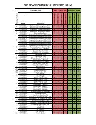
Contents / Table des matières <strong>Thermo</strong> <strong>Top</strong> C (12 Volt, Diesel)<br />
<strong>Top</strong>ic / Matière<br />
<strong>Heater</strong>s / Réchauffeur . . . . . . . . . . . . . . . . . . . . . . . . . . . . . . . . . . . . . . . . . . . . . . . . . . . . . . . . . . . . . . Page 33<br />
Parts for heater / Pièces pour le réchauffeur . . . . . . . . . . . . . . . . . . . . . . . . . . . . . . . . . . . . . . . . . . . . . . Figure 1<br />
Electrical parts / Pièces électriques . . . . . . . . . . . . . . . . . . . . . . . . . . . . . . . . . . . . . . . . . . . . . . . . . . . . . Figure 2<br />
Parts for fuel supply / Pièces afférentes au alimentation en <strong>com</strong>bustible . . . . . . . . . . . . . . . . . . . . . . . . . Figure 3<br />
Parts for <strong>com</strong>bustion air system / Pièces afférentes au système d'air <strong>com</strong>burant . . . . . . . . . . . . . . . . . . . Figure 3<br />
Parts for exhaust system / Pièces afférentes au système d'échappement . . . . . . . . . . . . . . . . . . . . . . . . . Figure 4<br />
Parts for heating water system / Pièces afférentes au système d’eau chaude. . . . . . . . . . . . . . . . . . . . . . Figure 4<br />
Diagnostic Tools / Outils Diagnostiques. . . . . . . . . . . . . . . . . . . . . . . . . . . . . . . . . . . . . . . . . . . . . . . . . . Figure 5<br />
For additional accesssory parts refer to the accessories catalogue.<br />
Pour d'autres accessoires consulter le catalogue d'accessoires.<br />
For replacement heater see / Pour le réchauffeur de rechange voyez:<br />
<strong>Thermo</strong> <strong>Top</strong> C . . . . .12 V Diesel . . . . . . . . . . . . . . . . . . . . . . . . . . . . . . . . . . . . . . . . . . . . . . . . . . . . . . Figure 1<br />
Column A/N: lndicates which parts are modified, which parts are new:<br />
A = modification N = new part<br />
Column Description: Sub-assemblies or <strong>com</strong>ponents (marked by a point) - offset to the right - are contained in<br />
the assembly which is offset one point less.<br />
Example:<br />
fuel pump = assembly<br />
solenoid valve = sub-assembly<br />
gasket = <strong>com</strong>ponent<br />
The parts dependent on 12 Volt with red label or dot<br />
voltage are marked: 24 Volt with green label or dot<br />
Séparation A/N: Afin de mettre en évidence les nouvelles pièces et les pièces transformées, vous trouverez<br />
le repère suivant:<br />
A = transformation N = nouvelles pièces<br />
Désignation abrégée: Les sous-ensembles marqués par points sont inclus dans les pièces les précédant et étant<br />
précédés d'un nombre de points inférieurs ou d'aucun point.<br />
Exemple:<br />
pompe à <strong>com</strong>bustible = pièce principale<br />
électrovanne = sous-ensemble inclus dans la pompe à <strong>com</strong>bustible<br />
joint torique = inclus dans I'électrovanne<br />
Pièces différentes selon 12 volts avec inscription rouge ou point rouge<br />
tension 12 ou 24 volts: 24 volts avec inscription verte ou point vert<br />
Subject to modification / Sous réserve de modifications<br />
32 Webasto Product N.A., Inc. www.techwebasto.<strong>com</strong>
Item<br />
Repére<br />
Quantity<br />
Nombre<br />
TTC<br />
Part No.<br />
Référence<br />
A/N<br />
Description<br />
Désignation<br />
<strong>Thermo</strong> <strong>Top</strong> C (TTC) - 12 Volt, Diesel <strong>Heater</strong>s / Réchauffeur<br />
1<br />
2-10<br />
1 89073K <strong>Thermo</strong> <strong>Top</strong> C - 12 V, Diesel replacement heater<br />
réchauffeur de rechange<br />
Parts for heater / Pièces pour le réchauffeur<br />
11<br />
12<br />
1 92995C burner (Diesel)<br />
brûleur (Gas-oil)<br />
12 V<br />
13<br />
14<br />
1 9001383A <strong>com</strong>bustion air fan<br />
turbine d’air<br />
12 V<br />
15 1 93008A circulation pump<br />
pompe de circulation<br />
U 4847 - 12 V<br />
16 1 93011C pump housing<br />
Corps de pompe<br />
193°<br />
17 1 93012C pump housing<br />
Corps de pompe<br />
axial<br />
18<br />
19<br />
1 92998E burner head + heat exchanger + control unit<br />
tête de brûleur + échangeur de chaleur + boîtier de <strong>com</strong>mande<br />
20 1 87394B universal mounting plate<br />
plat de support universel<br />
21 1 901088 mounting plate - heavy duty truck applications<br />
plat de support - applications résistantes de camion<br />
22 3 86889B screw<br />
vis<br />
EJOT PT 10 DG 60 x 18<br />
<strong>Thermo</strong> <strong>Top</strong> C (12 Volt, Diesel) - fig. 1<br />
Remarks<br />
Remarques<br />
with screws and gaskets / avec vis et<br />
joints<br />
with seals and screws / avec pièces<br />
d’étanchéité et vis<br />
for / pour U 4847<br />
for / pour U 4847<br />
for fastening bracket to heater / pour le<br />
support d'attache au réchauffeur<br />
www.webasto.us Webasto Product N.A., Inc. 33
Item<br />
Repére<br />
Quantity/<br />
Nombre<br />
TTC<br />
Part No.<br />
Référence<br />
A/N<br />
Description<br />
Désignation<br />
Electrical parts / Piéces électriques<br />
1 1 89372A A dosing pump - DP 30<br />
pompe doseur - DP 30<br />
12 V<br />
2 1 21499A clamp<br />
collier de fixation<br />
Ø 35mm<br />
3<br />
4<br />
1 462543 rubber anti-vibration mount<br />
silentbloc en caoutchouc<br />
5 1 462543 rubber anti-vibration mount<br />
silentbloc en caoutchouc<br />
M6<br />
6 1 255149 clamp<br />
collier de serrage<br />
7<br />
8-9<br />
1 131320 rubber mounting<br />
couche intermédiaire<br />
10 1 906108A timer - 1531<br />
temporisateur - 1531<br />
12 V<br />
11 1 90807A light bulb<br />
lampe<br />
12 V<br />
12 1 474630 mounting kit (digital timer)<br />
cadre avec support<br />
13 1 475866 mounting case<br />
habillage de montre<br />
14<br />
15-19<br />
1 905103 toggle switch<br />
interrupteur à levier<br />
12 V, illuminated/ illuminé<br />
<strong>Thermo</strong> <strong>Top</strong> C (12 Volt, Diesel) - fig. 2<br />
Remarks<br />
Remarques<br />
alternatives for item 3<br />
facultativement pour rep. 3<br />
3 preset times<br />
3 temps préaffichés<br />
with On/Off plate<br />
avec le plat "Marche/Arrêt"<br />
34 Webasto Product N.A., Inc. www.techwebasto.<strong>com</strong>
Item<br />
Repére<br />
Quantity/<br />
Nombre<br />
TTC<br />
Part No.<br />
Référence<br />
A/N<br />
20 X 32099A silicone seal<br />
joint de silicone<br />
21 X 84346A flat spring contact 2.8<br />
contact à ressort à lame<br />
22 X 84348A jack 0.75<br />
contact à douille<br />
23 X 24990A receptacle<br />
cosse femelle<br />
24 1 5000756A plug connector 2 pole, 2.8<br />
25-26<br />
douille à cosses femelles 2 poteau, 2.8<br />
27 1 5000524A wiring harness - Thomas Bus<br />
faisceau des câbles - Thomas Bus<br />
X = Quantity as required / Nombre suivant les besoins<br />
Description<br />
Désignation<br />
for digital timer connector / pour fiche<br />
d’horloge<br />
metering pump<br />
pompe de dosage<br />
Remarks<br />
Remarques<br />
Thomas Bus - replacement part<br />
Autobus de Thomas - pièce de rechange<br />
www.webasto.us Webasto Product N.A., Inc. 35
Item<br />
Repére<br />
Quantity/<br />
Nombre<br />
TTC<br />
Part No.<br />
Référence<br />
A/N<br />
Description<br />
Désignation<br />
Parts for fuel supply / Pièces afférentes au alimentation en <strong>com</strong>bustible<br />
1 X 50483931A fuel line<br />
tuyau de <strong>com</strong>bustible<br />
id.Ø 2 x od.Ø 5mm<br />
2 1 903200A fuel standpipe<br />
dispositif de prise, réservoir<br />
Ø 5.5mm<br />
3 1 5000553A fuel standpipe<br />
dispositif de prise, réservoir<br />
Ø 5.5mm<br />
4 5 50484032B fuel line connector<br />
tuyau de <strong>com</strong>bustible connecteur.<br />
id.Ø 4.5mm x 50mm lg.<br />
5 X 34859B fuel line connector - 90° id.Ø 4.5mm<br />
tuyau de <strong>com</strong>bustible connecteur - 90°<br />
6 10 330027 hose clamp<br />
collier de serrage<br />
Ø 10mm<br />
7 X 379670 hose clamp<br />
pince pour tuyau flexible<br />
Ø 12mm<br />
8<br />
9<br />
X 463949 hose clamp<br />
collier de serrage<br />
Ø 10mm<br />
10<br />
11-20<br />
1 50487171A fuel filter<br />
filtre de <strong>com</strong>bustible<br />
Parts for <strong>com</strong>bustion air system / Pièces afférentes au système d’air <strong>com</strong>burant<br />
21 1 29516B protecting cap<br />
capot de protection<br />
Ø 27mm<br />
22 X 243744 hose clamp<br />
pince pour tuyau flexible<br />
Ø 20 - 27mm<br />
<strong>Thermo</strong> <strong>Top</strong> C (12 Volt, Diesel) - fig. 3<br />
Remarks<br />
Remarques<br />
per meter<br />
au Métre<br />
alternate part 35320A<br />
article alternatif 35320A<br />
36 Webasto Product N.A., Inc. www.techwebasto.<strong>com</strong>
Item<br />
Repére<br />
Quantity/<br />
Nombre<br />
TTC<br />
Part No.<br />
Référence<br />
A/N<br />
23 X 362891 pipe clip Ø 29mm<br />
collier de fixation<br />
24 1 66113A air intake silencer<br />
silencieux d'aspiration d'air<br />
25 1 5023298A flexible pipe PAP<br />
tuyau flexible<br />
Ø 22mm x 500mm PAP<br />
26 1 5000641A flexible pipe AA<br />
tuyau flexible<br />
Ø 22mm x 450mm AA<br />
27 1 5000642A flexible pipe AA<br />
tuyau flexible<br />
Ø 22mm x 500mm AA<br />
28 1 5000643A flexible pipe AA<br />
tuyau flexible<br />
Ø 22mm x 1m AA<br />
29 1 5000644A flexible pipe AA<br />
tuyau flexible<br />
Ø 22mm x 1.5m AA<br />
30 X 5000645A flexible pipe AA<br />
tuyau flexible<br />
Ø 22mm x 5m AA<br />
X = Quantity as required / Nombre suivant les besoins<br />
Description<br />
Désignation<br />
Remarks<br />
Remarques<br />
<strong>com</strong>bustion tubing - Thomas Bus<br />
tuyauterie de <strong>com</strong>bustion - Thomas Bus<br />
<strong>com</strong>bustion tubing<br />
tuyauterie de <strong>com</strong>bustion<br />
www.webasto.us Webasto Product N.A., Inc. 37
Item<br />
Repére<br />
Quantity/<br />
Nombre<br />
TTC<br />
Part No.<br />
Référence<br />
A/N<br />
Description<br />
Désignation<br />
<strong>Thermo</strong> <strong>Top</strong> C (12 Volt, Diesel) - fig. 4<br />
Remarks<br />
Remarques<br />
Parts for exhaust system / Pièces afférentes au système d’échappement<br />
1 1 86450C exhaust silencer Ø 22mm<br />
rustproof<br />
silencieux d’echappement<br />
antirouille<br />
2 1 20844E exhaust silencer<br />
silencieux d’echappement<br />
Ø 22mm<br />
3 X 242780 angle bracket<br />
support équerre<br />
4 X 242888 mounting strip<br />
ruban de montage<br />
5 1 20965A exhaust clamp<br />
bride d'échappement<br />
Ø 24 - 26mm<br />
6 X 405256 pipe clip<br />
collier de serrage<br />
Ø 25mm<br />
7 1 50900126A flexible exhaust pipe,<br />
with cap<br />
Ø 22mm x 1m, stainless steel Thomas Bus - replacement part<br />
pipe d'échappement<br />
flexible, avec capot<br />
Ø 22mm x 1m, acier inoxydable Autobus de Thomas - pièce de rechange<br />
8 X 5000322A flexible exhaust pipe Ø 22mm x 5m<br />
stainless steel<br />
pipe d'échappement flexible<br />
acier inoxydable<br />
9 X 5000323A flexible exhaust pipe Ø 22mm x 10m<br />
stainless steel<br />
pipe d'échappement flexible<br />
acier inoxydable<br />
10 X 50337390A flexible exhaust pipe Ø 22mm x 20m<br />
stainless steel<br />
pipe d'échappement flexible<br />
acier inoxydable<br />
11 1 28472C exhaust elbow<br />
coude d'échappement<br />
Ø 22mm<br />
12 X 18137A rubber ring (red)<br />
anneau caoutchouc (rouge)<br />
38 Webasto Product N.A., Inc. www.techwebasto.<strong>com</strong>
Item<br />
Repére<br />
13 1 24048A protection cap Ø 26.3mm<br />
capot de protection<br />
14-20<br />
Quantity/<br />
Nombre<br />
TTC<br />
Part No.<br />
Référence<br />
A/N<br />
Parts for heating water system / Pièces afférentes au système d’eau chaude<br />
21 X 50126840A formed hose<br />
tuyau formé<br />
Ø 20mm x 2.2m lg.<br />
22 X 66934B hose connector<br />
connecteur de tuyau<br />
Ø 20 x 20mm<br />
23 66908B hose connector<br />
connecteur de tuyau<br />
Ø 18 x 20mm<br />
24 2 900611 hose connector<br />
connecteur de tuyau<br />
Ø 5/8” x 3/4”<br />
25 X 901052 hose clamp<br />
pince pour tuyau flexible<br />
Ø 19 - 27mm<br />
26 X 901097 hose clamp<br />
pince pour tuyau flexible<br />
Ø 23 - 32mm<br />
X = Quantity as required / Nombre suivant les besoins<br />
Description<br />
Désignation<br />
Remarks<br />
Remarques<br />
180° formed ends<br />
extrémités formées par 180°<br />
alternate item / article alternatif 66908B<br />
www.webasto.us Webasto Product N.A., Inc. 39
Item<br />
Repére<br />
Quantity<br />
Nombre<br />
TTC<br />
Part No.<br />
Référence<br />
A/N<br />
1 2<br />
Description<br />
Désignation<br />
Diagnostic Tools / Outils Diagnostiques<br />
1 1 1301728B A PC diagnosis<br />
diagnostic PC<br />
2 1 92566B A test adapter<br />
examinez l'adapteur<br />
3 1 50000043 N dielectric silicone grease<br />
graisse diélectrique de silicone<br />
2 oz.<br />
no fig. 1 63378A workshop manual - English <strong>Thermo</strong> Z/C<br />
manuel d'atelier - l'anglais <strong>Thermo</strong> Z/C<br />
no fig. 1 907636 troubleshooting guide<br />
guide de dépannage<br />
<strong>Thermo</strong> <strong>Top</strong> C (12 Volt, Diesel) - fig. 5<br />
Dielectric Silicone<br />
Grease 2 oz. Tube<br />
40 Webasto Product N.A., Inc. www.techwebasto.<strong>com</strong><br />
3<br />
Remarks<br />
Remarques<br />
includes software and adapter / inclut le<br />
logiciel et l'adapteur 92566B<br />
for electrical connectors<br />
pour les connecteurs électriques<br />
available at www.techwebasto.<strong>com</strong><br />
disponible à www.techwebasto.<strong>com</strong><br />
available at www.techwebasto.<strong>com</strong><br />
disponible à www.techwebasto.<strong>com</strong>
Org. 06/2004 Rev. 10/2010 P/N 5000838B<br />
Webasto Product N.A., Inc.<br />
15083 North Road<br />
Fenton, MI 48430<br />
Technical Assistance Hotline<br />
USA: (800) 555-4518<br />
Canada: (800) 667-8900<br />
Numéro d’assistance technique<br />
É.-U. (800) 555-4518<br />
Canada (800) 667-8900<br />
www.webasto.us<br />
www.techwebasto.<strong>com</strong>