Montageanleitung Einbausatz AUTA 74 F W 210 823 417-001
Montageanleitung Einbausatz AUTA 74 F W 210 823 417-001
Montageanleitung Einbausatz AUTA 74 F W 210 823 417-001

Create successful ePaper yourself
Turn your PDF publications into a flip-book with our unique Google optimized e-Paper software.
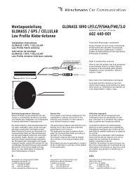
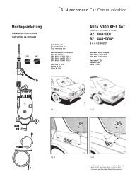
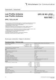
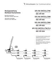
<strong>Montageanleitung</strong><br />
<strong>Einbausatz</strong><br />
Installation instructions<br />
Mounting set<br />
Instruction de montage<br />
Set de montage<br />
38,5°<br />
A535<br />
<strong>AUTA</strong> <strong>74</strong> F W <strong>210</strong><br />
Bestell-Nr. / Ord. code / Réf. de cde.<br />
<strong>823</strong> <strong>417</strong>-<strong>001</strong><br />
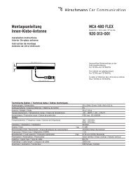
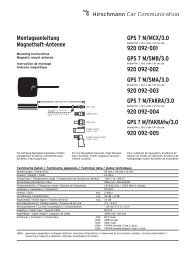
Für Automatic-Antennen-Grundtyp<br />
For automatic antenna basic type<br />
Pour l'antenne automatique de base<br />
<strong>AUTA</strong> 6000 KE-F 10<br />
921 504-002<br />
1355 B<br />
Zum Einbau in:<br />
For installation in:<br />
Pour montage sur:<br />
Mercedes E-Klasse Limousinen<br />
E 200 - E 420 Limousine<br />
E 50 AMG Limousine<br />
Baureihe / Series / Série W <strong>210</strong><br />
Fig. 1<br />
90<br />
81<br />
A405
Fig. 2<br />
➔<br />
Fig. 6<br />
Fig. 7<br />
2<br />
➔<br />
➔<br />
Fig. 3 Fig. 4<br />
2x<br />
9x<br />
1x<br />
A397<br />
+<br />
3x<br />
12 V<br />
➔<br />
➔<br />
CODE<br />
➔<br />
➔<br />
Fig. 5
➔<br />
➔<br />
➔<br />
➔<br />
Fig. 8<br />
Fig. 11<br />
Fig. 13 Fig. 14<br />
Fig. 15<br />
Fig. 16<br />
➔<br />
➔<br />
R<br />
➔<br />
M6<br />
Fig. 9 Fig. 10<br />
Fig. 12<br />
R<br />
Fig. 17<br />
Minus<br />
Karosserie<br />
Ø 6,5 mm<br />
3
Einbau<br />
Der Einbau der Automatic-Antennen<br />
<strong>AUTA</strong> 6000 KE-F 10 mit dem <strong>Einbausatz</strong><br />
<strong>AUTA</strong> <strong>74</strong> F W <strong>210</strong> erfolgt bei den angegebenen<br />
Mercedes-Benz E-Klasse-Limousinen<br />
in den linken hinteren Kotflügel (Fig. 1<br />
und 7).<br />
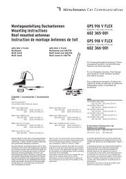
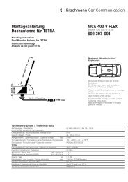
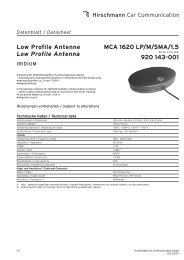
Vorbereitungen am Fahrzeug<br />
Batterie<br />
Zur Sicherheit Batterie Minuspol abklemmen.<br />
Hierzu im Innenraum die hintere<br />
Sitzbank ausbauen (Fig. 2).<br />
Linke hintere Wagentüre<br />
Im Bereich der linken hinteren Wagentüre<br />
Schwellerleiste entfernen (1 Blechschraube,<br />
2 Klipse). Dichtleiste am Türrahmen<br />
abziehen (Fig. 3).<br />
C-Säule links<br />
Abdeckung über Kabelführung aushebeln<br />
(3 Klammern) und C-Säulenabdeckung<br />
entfernen, dazu Handgriff abschrauben.<br />
2 Klipse vom Türrahmen ausrasten,<br />
danach 2 Klammern durch Hintergreifen<br />
mit der Hand ausrasten. C-Säulenverkleidung<br />
etwas vorziehen und abheben<br />
(Fig. 4 und 5).<br />
Kofferraum (Fig. 6)<br />
Im Kofferraum Bodeneinlage entfernen.<br />
Wagenheber herausnehmen.<br />
Heckleiste lösen (9 Klipse aushebeln und<br />
die 2 Einhängehaken abschrauben).<br />
Linke Seitenwandabdeckung entfernen<br />
(1 Spreizdorn aushebeln).<br />
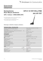
Montagearbeiten am Fahrzeug<br />
An der Einbaustelle nach Fig. 7 die beiliegende<br />
Bohrschablone anlegen, das<br />
Karosserieloch anzeichnen und maßhaltig<br />
einarbeiten. Zum Schutz des Lackes<br />
vorher mit Klebeband abkleben.<br />
Die Bohrung entgraten und die blanke<br />
Kante gegen Korrosion mit Grundlack<br />
bestreichen und antrocknen lassen.<br />
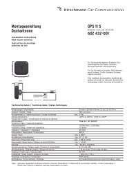
An der freigelegten C-Säule das HF-Kabel<br />
und die Steuerleitung (blau) vom Antennenverstärker<br />
abschließen, ausklammern,<br />
ein kurzes Stück ausbinden und entsprechend<br />
den vorhandenen Leitungen in den<br />
Kofferraum verlegen (Fig. 8, 9 und 10).<br />
Die beigefügte Motorleitung wie folgt<br />
anschließen:<br />
Rote Ader entlang den vorhandenen<br />
Leitungen in den Innenraum bis unter die<br />
hintere Sitzbank verlegen. Die isolierte<br />
Flachsteckhülse aufcrimpen, Kabelsicherung<br />
und Anschlußkabel bis zum Batterie-<br />
Pluspol verlegen und anklemmen (Fig. 11).<br />
Schwarze Ader entlang der Seitenwand<br />
zur linken Heckleuchte verlegen und an<br />
vorhandenen Massekontakt anschließen<br />
(Fig. 12).<br />
Weiße Ader mit isoliertem Flachstecker<br />
an der in den Kofferraum verlegten Steuerleitung<br />
(blau) aufstecken.<br />
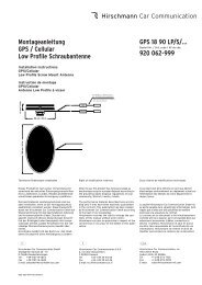
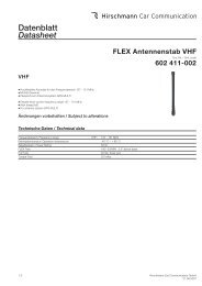
Einbau der Antenne<br />
Befestigungsteil „R“ am Antennengehäuse<br />
wie abgebildet einsetzen (Fig. 13).<br />
Halter am Befestigungsteil „R“ mit M5-<br />
Sechskantschraube, Scheibe und Mutter<br />
befestigen (Fig. 14).<br />
Die Dichttülle von oben in das Karosserieloch<br />
einsetzen (Fig. 15).<br />
Das Antennenkabel am Antennenstutzen<br />
fest anschrauben und die Motorleitung<br />
einstecken.<br />
Die Antenne vom Kofferraum aus in die<br />
bereits eingesetzte Dichttülle eindrücken;<br />
dazu empfiehlt es sich, den Kugelstutzen<br />
vorher mit etwas Fett zu bestreichen, z. B.<br />
mit <strong>AUTA</strong> 115 (Fig. 15 und 16).<br />
Halter an dem vorhandenen Langloch der<br />
Verstrebungswand mit M6-Schraube<br />
anschrauben (Fig. 14 und 16).<br />
Für das Masseband im oberen Bereich<br />
ein Loch mit Ø 6,5 mm bohren. Um die<br />
Bohrung herum blank schaben, mit Kontaktschutzfett<br />
einstreichen und wie abgebildet<br />
mit M6-Schraube, Scheiben und<br />
Mutter anschließen (Fig. 15 und 16).<br />
Nach Beendigung der Installation Batterie<br />
wieder anklemmen und Antenne durch<br />
Einschalten des Radios ausfahren. Die<br />
Neigung des Teleskops kontrollieren, die<br />
Stellung der Antenne eventuell korrigieren<br />
und danach die Schrauben am Halter<br />
fest anziehen (Fig. 16).<br />
Die Kappe von oben auf die Dichttülle<br />
aufsetzen, leicht nachdrücken bis sie eingerastet<br />
ist. Bei korrektem Einbau muß<br />
die Außenkante der Karosserietülle<br />
gleichmäßig an der Karosserieoberfläche<br />
anliegen (Fig. 15 und 17).<br />
Auskleidung im Kofferraum, entfernte<br />
Verkleidungen und den Rücksitz im Innenraum<br />
wieder einbauen.<br />
D GB<br />
Pflegehinweise<br />
Reinigen Sie bitte das Teleskop möglichst<br />
oft von anhaftendem Staub und Schmutz.<br />
Verwenden Sie nur ganz wenig von unserem<br />
Spezialfett in Tuben <strong>AUTA</strong> 235 oder benutzen<br />
Sie unser Autoantennen-Pflegetüchlein<br />
<strong>AUTA</strong> 135, das gleichzeitig reinigt<br />
und fettet.<br />
Bitte die beigefügte Gebrauchs- und<br />
Pflegeanleitung mit Garantiekarte und<br />
den beiden Autoantennen-Pflegetüchlein<br />
(<strong>AUTA</strong> 135) dem Kunden aushändigen.<br />
Ersatzteile bitte unter den angegebenen<br />
Nummern bestellen.<br />
Technische Änderungen vorbehalten.<br />
Die beschriebenen Leistungsmerkmale sind nur<br />
dann verbindlich, wenn sie bei Vertragsabschluss<br />
ausdrücklich vereinbart wurden.<br />
Diese Druckschrift wurde von<br />
Hirschmann Car Communication GmbH auf Übereinstimmung<br />
mit den beschriebenen Antennen<br />
und Antennenzubehör (Kabel, Stecker etc.)<br />
geprüft. Dennoch können Abweichungen hinsichtlich<br />
der Richtigkeit oder Genauigkeit nicht ausgeschlossen<br />
werden, sodass Hirschmann für die<br />
vollständige Übereinstimmung keine Gewähr<br />
übernimmt. Hirschmann behält sich das Recht<br />
vor, den Inhalt dieser Druckschrift ohne Ankündigung<br />
zu ändern.<br />
Installation<br />
Installation of the automatic antenna<br />
<strong>AUTA</strong> 6000 KE-F 10 with the installation set<br />
<strong>AUTA</strong> <strong>74</strong> F W <strong>210</strong> is appointed left-side in<br />
the rear wings of the stated Mercedes Emodel<br />
limousines (fig. 1 and 7).<br />
Preparing the vehicle<br />
Battery<br />
Disconnect the minus pole of the battery<br />
for security. Remove the rear seat bench<br />
from the passenger compartment therefore<br />
(fig. 2).<br />
Left-hand rear door<br />
Remove the sill strip at the left-hand rear<br />
door (1 sheet metal screw, 2 clips). Remove<br />
the sealing strip from the door frame<br />
(fig. 3).<br />
C-pillar left hand<br />
Prise out the cap covering the cable guide<br />
(3 clasps) and remove the C-pillar cover<br />
(to do this, unscrew the handhold). Release<br />
the clips from the door frame, release<br />
the 2 clasps behind the frame using your<br />
hand, and then pull out the C-pillar panel<br />
slightly and remove (fig. 4 and 5).<br />
Luggage compartment (fig. 6)<br />
Remove the floor cover panel from the<br />
luggage compartment.<br />
Remove the jack.<br />
Release the rear strip (prise out the 9<br />
clips and unscrew the 2 mounting hooks).<br />
Remove the cover panel on the left-hand<br />
side (prise out the 1 split pin).<br />
Apply the attached drilling pattern according<br />
to fig. 7, mark the installation place<br />
and properly drill the hole. Before drilling<br />
cover the paintwork with adhesive tape<br />
for protecting.<br />
Remove the burr, spread the bare edge<br />
with primer to protect against corrosion<br />
and allow to dry.<br />
At the cleared C-pillar, disconnect the HF<br />
cable and control cable (blue) from the<br />
antenna amplifier. Release these cables<br />
and then pull out a short length and<br />
install in the luggage compartment corresponding<br />
to the existing cables<br />
(fig. 8, 9 and 10).<br />
Laying cables:<br />
Red lead: Install the red lead along the<br />
existing cables in the passenger compartment<br />
so that it reaches below the rear<br />
seat bench. Crimp on the insulated pushon<br />
receptacle. Lay the cable guard and<br />
connection cable up to the positive terminal<br />
of the battery and then connect<br />
(fig. 11).<br />
Black lead: Install the black lead along<br />
the side panel to the left-hand rear-lamp<br />
unit and connect to the existing ground<br />
contact (fig. 12).<br />
White lead: Connect the white lead with<br />
the insulated flat connector to the control<br />
cable (blue) installed in the luggage compartment.<br />
Antenna installation<br />
Insert the fixing part „R“ to the antennahousing<br />
at the position as shown (fig. 13).<br />
Fasten the bracket to the fixing part „R“<br />
using the M5 hex head screw, washer<br />
and nut (fig. 14).<br />
Insert the sealing sleeve from top into the<br />
car body hole (fig. 15).<br />
4
Tighten the antenna cable to the antenna<br />
case and plug-in the motor cable.<br />
Insert the antenna from the luggage-boot<br />
through the sleeve inserted before; it is<br />
recommended to preciously apply some<br />
grease, e.g. <strong>AUTA</strong> 115 to the spherical<br />
antenna head (fig. 15 and 16).<br />
Fasten the bracket at the existing oblong<br />
hole to the brace wall (fig. 14 and 16).<br />
Drill a hole (Ø 6.5 mm) for the grounding<br />
strip in the upper section. Scrape the<br />
drill-hole clean, smear with contact protective<br />
grease, and connect using M6<br />
bolt, washers, and nut as shown in the<br />
illustration (fig. 15 and 16).<br />
After completion of installation reconnect<br />
battery and extend the antenna by switching<br />
on the radio. Check the angle of the<br />
telescope, adjust if necessary and then<br />
tighten the screws at the bracket (fig. 16).<br />
Apply the cap on top of the sleeve and<br />
press slightly until snapping-on. If installed<br />
correctly, the outer edge of the body<br />
protection sleeve should make uniform<br />
contact with the body surface (fig. 15<br />
and 17).<br />
Replace all removed linings and reinstall<br />
the rear seat in the passenger compartment.<br />
Maintenance<br />
Please clean the telescope as often as possible<br />
of adhering dust and dirt. Use only a<br />
little of our special grease <strong>AUTA</strong> 235 supplied<br />
in tubes or our car antenna tissue<br />
<strong>AUTA</strong> 135 for both cleaning and greasing.<br />
Please hand over to the customer the<br />
enclosed instructions for use and<br />
maintenance with guarantee certificate<br />
as well as the two car antenna tissues<br />
(<strong>AUTA</strong> 135).<br />
Please state order codes when ordering<br />
spare parts.<br />
Right of modification reserved.<br />
The performance features described here are binding<br />
only if they have been expressly guaranteed<br />
in the contract.<br />
This publication has been created by Hirschmann<br />
Car Communication GmbH according to the best<br />
of our knowledge.<br />
Hirschmann reserves the right to change the<br />
contents of this manual without prior notice.<br />
Hirschmann can give no guarantee in respect of<br />
the correctness or accuracy of the details in this<br />
publication.<br />
F<br />
Installation<br />
Le montage de l'antenne automatique<br />
<strong>AUTA</strong> 6000 KE-F 10 avec le set de montage<br />
<strong>AUTA</strong> <strong>74</strong> F W <strong>210</strong> se fait sur les berlines<br />
indiqués de Mercedes classe E sur l'aile<br />
arrière gauche (fig.1 et 7).<br />
Preparing the vehicle<br />
La batterie<br />
Pour des raisons de sécurité, débrancher<br />
le pôle négatif de la batterie. Démonter la<br />
banquette arrière dans l'habitacle (fig. 2).<br />
La portière arrière de gauche<br />
Retirer la baguette de seuil au niveau de<br />
la portière arrière de gauche (1 vis à tôle,<br />
2 clips). Retirer la baguette d'étanchéité<br />
du cadre de la porte (fig. 3).<br />
Le montant C de gauche<br />
Dégager le cache au-dessus de la goulotte<br />
de câbles (3 pinces) et retirer le cache<br />
du montant C en dévissant, pour ce faire,<br />
la poignée. Dégager les 2 clips du cadre<br />
de la portière puis dégager les 2 pinces<br />
en passant la main derrière, avancer<br />
légèrement l'habillage du montant C et<br />
l'enlever (fig. 4 et 5).<br />
Le coffre (fig. 6)<br />
Retirer le tapis de sol dans le coffre<br />
Sortir le cric.<br />
Libérer la baguette arrière (dégager les 9<br />
clips et dévisser les 2 crochets).<br />
Retirer le cache de gauche de la paroi<br />
latérale (dégager 1 broche à expansion).<br />
Montage à la voiture<br />
Appliquer le gabarit de perçage ci-inclus<br />
à l'endroit de montage selon fig. 7, marquer<br />
le trou de perçage pour l'antenne<br />
sur la carrosserie et percer précisement.<br />
Auparavant, coller un ruban adhésif pour<br />
protéger la laque.<br />
Supprimer les bavures du perçage,<br />
enduire le bord nu de laque de base<br />
comme protection contre la corrosion et<br />
laisser sécher.<br />
Débrancher le câble HF et le câble de<br />
commande (bleu), sur le montant C<br />
dégagé de l'amplificateur d'antenne, le<br />
libérer, ligaturer un court morceau et le<br />
poser dans le coffre conformément aux<br />
câbles existants (fig. 8, 9 et 10).<br />
Brancher le câble de moteur joint de la<br />
manière suivante:<br />
Conduite rouge: Poser le câble rouge le<br />
long des câbles existants, dans l'habitacle,<br />
jusque sous la banquette arrière.<br />
Sertir l'alvéole pour contact plat isolée,<br />
poser le protège-câble et le câble de raccordement<br />
jusqu'au pôle positif de la batterie<br />
et le brancher (fig. 11).<br />
Conduite noire: Poser le câble noir le<br />
long de la paroi latérale, vers le feu arrière<br />
de gauche et le raccorder au contact de<br />
masse existant (fig. 12).<br />
Conduite blanche: Raccorder le câble<br />
blanc avec la fiche plate isolée au câble<br />
de commande (bleu) posé dans le coffre.<br />
Montage de l'antenne<br />
Mettre la pièce de fixation „R“ au boîtier<br />
de l'antenne dans la position de la fig. 13.<br />
Fixer le support à la pièce de fixation „R“<br />
avec le boulon hexagonal M5, la rondelle<br />
et l'écrou (fig. 14).<br />
Placer le manchon étanchéité d'en haut<br />
dans le perçage de la carrosserie (fig. 15).<br />
Visser à fond le câble d'antenne à la rallonge<br />
d'antenne et enficher la conduite<br />
du moteur.<br />
Du côté du coffre, presser l'antenne dans<br />
le manchon étanchéité déjà mis; pour<br />
cela nous vous recommandons de commencer<br />
par enduire la rallonge à bille<br />
d'un peu de graisse, p. ex. avec <strong>AUTA</strong> 115<br />
(fig. 15 et 16).<br />
Visser le support au trou oval existant à<br />
l'entretoise de la carrosserie (fig. 14 et 16).<br />
Percer, pour la tresse de masse, un trou<br />
de 6,5 mm de diamètre dans la partie<br />
supérieure, mettre le métal à nu autour<br />
du perçage, enduire de graisse de protection<br />
pour contacts et effectuer le raccordement<br />
comme indiqué sur l'illustration,<br />
avec le boulon M6, les rondelles et<br />
l'écrou (fig. 15 et 16).<br />
Une fois finie l'installation, rébrancher la<br />
batterie et sortir l'antenne en mettant en<br />
marche la radio. Contrôler l'inclinaison<br />
du télescope; si besoin est, corriger la<br />
position de l'antenne et ensuite serrer à<br />
fond les vis au support (fig. 16).<br />
Placer le recouvrement d'en haut sur le<br />
manchon d'étanchéité, appuyer légèrement,<br />
jusqu'à ce qu'il encliquette. Si le<br />
montage est correct, le bord extérieur du<br />
manchon doit toucher la surface de la<br />
carrosserie de manière homogène<br />
(fig. 15 et 17).<br />
Remonter le revêtement du coffre ainsi<br />
que les autres revêtements démontés et<br />
remonter le siège arrière dans l'habitacle.<br />
Conseils d'entretien<br />
Veuillez nettoyer le télescope le plus souvent<br />
possible de la poussière adhérente et<br />
de la saleté. N'utilisez que très peu de notre<br />
graisse spéciale en tube <strong>AUTA</strong> 235 ou bien<br />
notre essuie-antenne <strong>AUTA</strong> 135 qui nettoie<br />
et graisse en même temps.<br />
Veuillez transmettre au client le mode<br />
d'emploi et d'entretien ci-jointe avec le<br />
bulletin de garantie et les deux essuiesantenne<br />
(<strong>AUTA</strong> 135).<br />
Veuillez commander les pièces détachées<br />
sous les numéros indiqués.<br />
Sous réserve de modifications techniques.<br />
La société Hirschmann Car Communication GmbH<br />
ne se porte garante de la véracité des informations<br />
techniques que si elles ont été spécifiées de<br />
manière expresse à la signature du contrat.<br />
Le contenu de ce document a été minutieusement<br />
contrôlé afin de s’assurer qu’il corresponde<br />
bien aux antennes et accessoires (câbles,<br />
connecteurs) décrits. Toutefois, Hirschmann ne<br />
peut en aucun cas être tenu responsable de<br />
l’exactitude de ces informations. Hirschmann se<br />
réserve le droit de modifier sans préavis le contenu<br />
de ce document.<br />
5
Hirschmann Car Communication GmbH<br />
Stuttgarter Strasse 45 - 51<br />
D-72654 Neckartenzlingen<br />
Tel (07127) 14-1873<br />
Fax (07127) 14-1428<br />
025 081-<strong>001</strong>-01-396-N<br />
Printed in Federal Republic of Germany . Imprimé en République Fédérale d´Allemagne