APC Back-UPS Pro® - APC Media
APC Back-UPS Pro® - APC Media
APC Back-UPS Pro® - APC Media

You also want an ePaper? Increase the reach of your titles
YUMPU automatically turns print PDFs into web optimized ePapers that Google loves.
4<br />
3. Presentation<br />
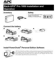
3.1 Front panel<br />
Press the on/of on/of on/off on/of button with the <strong>UPS</strong> plugged in to turn the <strong>UPS</strong> on or off. See Sec. 5.1.<br />
On/of On/off On/of also activates the <strong>UPS</strong>’s self-test. See section 5.2.<br />
The over er er erload er load LED illuminates when the loads connected to the <strong>UPS</strong> exceed the <strong>UPS</strong>’s power capacity. See<br />
section 6.2.<br />
The replace place ba batter ba tter ttery tter LED illuminates when the <strong>UPS</strong>’s battery is no longer useful and must be replaced. See<br />
section 10.<br />
The on-ba on-ba on-batter on-ba tter ttery tter LED illuminates when the <strong>UPS</strong> is supplying battery power to the loads.<br />
The on-line on-line LED means that filtered utility line is passing through the <strong>UPS</strong> to your equipment.<br />
The input input input po power po er connector connector is a power cord with a NEMA 5-15P connector.<br />
The output output po power po er receptacles are NEMA 5-15R type.<br />
The RJ-45/RJ-11 modular combination is used for tele telephone/netw<br />
tele phone/netw phone/networ<br />
phone/netw or ork or k sur surge sur e e pr protection pr otection with single telephone<br />
lines and 10Base-T networks. See section 4.5.<br />
The computer computer interf interface interf ace por port por is for <strong>UPS</strong> monitoring and control. See section 4.4.