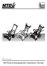
MTD Products Aktiengesellschaft • Saarbrücken ... - MTD Europe
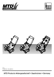
MTD Products Aktiengesellschaft • Saarbrücken ... - MTD Europe
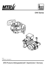
MTD Products Aktiengesellschaft • Saarbrücken ... - MTD Europe

Create successful ePaper yourself
Turn your PDF publications into a flip-book with our unique Google optimized e-Paper software.
1<br />
3 4<br />
5<br />
D03<br />
FORM NO. 769-00356<br />
<strong>MTD</strong> <strong>Products</strong> <strong>Aktiengesellschaft</strong> <strong>•</strong> <strong>Saarbrücken</strong> <strong>•</strong> Germany<br />
2<br />
6
7<br />
9<br />
11<br />
1.<br />
2.<br />
2<br />
8<br />
10<br />
12
13<br />
15<br />
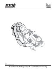
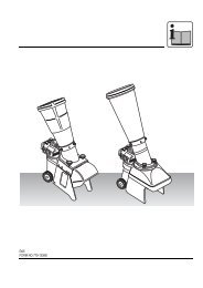
DE Montage Grasfangkorb an 500er Serie<br />
Beachten Sie die Sicherheitshinweise in der Bedienungsanleitung des Gerätes<br />
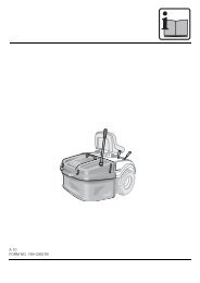
1. Befestigen Sie das untere Auswurfrohrstück mit dem Spanngummi an dem Mähdeck (Bild 1 – 4).<br />
2. Halterung (Bild 5), mit den Haken voran, in die Schlitze der Rückwand einführen und nach unten in die vorhandenen<br />
Bolzen (innen im Rahmen) drücken (Bild 6 und 7).<br />
Achtung: Achten Sie auf festen Sitz der Halterung (Einrasten der Haken auf den Bolzen).<br />
3. Sichern Sie die Halterung mit dem Bolzen und Splint (Bild 8 und 9).<br />
4. Montieren Sie den Grasfangdeckel, indem Sie das Stützrohr durch die beiden äußeren Löcher stecken (Bild 10).<br />
5. Hängen Sie die Grasfangsäcke ein (Bild 11 und 12).<br />
6. Führen Sie das obere Ende des Auswurfrohres in Öffnung des Grasfangdeckes ein (Bild 13).<br />
7. Schieben Sie die 2 Auswurfrohrstücke zusammen und fixieren diese mit den Spanngummis (Bild 14 und 15).<br />
Bedienung: Entleeren der Grasfangeinrichtung<br />
<strong>•</strong> Gerät abschalten<br />
<strong>•</strong> Feststellbremse arretieren<br />
<strong>•</strong> Grasfangdeckel hochklappen<br />
<strong>•</strong> Grasfangkörbe herausnehmen<br />
Zusatzinformation: Um eine optimale Funktion der Grasfangeinrichtnung zu erreichen sollten ggf. die „Highlift-Messer“<br />
(optional) montiert werden (Anzugsdrehmoment der Messerschraube 122 Nm). Wenden Sie sich bitte dann entsprechend<br />
an Ihren Händler vor Ort.<br />
3<br />
14<br />
16
EN Mounting the grass catcher basket on the 500 series<br />
Follow the safety instructions in the operating manual for the unit<br />
1. Attach the lower chute part to the cutting deck by using the rubber strap (Fig.1 – 4).<br />
2. Guide the catcher support bracket (Fig.5) with the hooks forward through the vertical slots in the rear frame and press it<br />
down so it slides into the two bolts inside the frame (Fig. 6 and 7).<br />
NOTE: Ensure the support bracket hooks to be seated into the two bolts inside the frame.<br />
3. Secure the catcher support bracket with the bolt and hair pin (Fig. 8 and 9).<br />
4. Attach the grass catcher cover by inserting the support tube through the two outer holes (Fig. 10).<br />
5. Attach the grass catcher bags (Fig. 11 and 12).<br />
6. Slide the upper chute half into the opening of the grass catcher cover (Fig. 13).<br />
7. Assemble the two chute halfs and secure them with the rubber straps (Fig. 14 and 15).<br />
Operation: Emptying the grass catcher<br />
<strong>•</strong> Switch off the unit<br />
<strong>•</strong> Lock the parking brake<br />
<strong>•</strong> Lift up the grass catcher cover<br />
<strong>•</strong> Take out the grass catcher baskets<br />
Additional information: To ensure that the grass catcher functions properly, the “Highlift” blade (optional) may have to be<br />
attached (tightening torque of the blade bolt 122 Nm). If so, please get in touch with your dealer on site.<br />
FR Montage du panier de ramassage de l'herbe sur la série 500<br />
Veuillez respecter les consignes de sécurité figurant dans la notice d'utilisation de l'appareil<br />
1. Fixer la partie basse du canal d’ejection avec les attaches caoutchouc au carter (fig.1 – 4).<br />
2. Introduire le support (fig. 5) avec les crochets vers l’avant dans les rainures de la plaque arriére et le pousser vers<br />
le bas (fig. 6 et 7).<br />
Attention: Veritier la bonne fixation du support (enclenchement des crochets sur les axes).<br />
3. Securisez le support avec le boulon et la coupille élastique.<br />
4. Montez le couvercle du bac de ramassage : faites passer le tuyau d'appui par les deux trous extérieurs (fig. 10).<br />
5. Accrochez les sacs de ramassage (fig. 11 et 12).<br />
6. Inserer la partie haute du canal d’ejection dans l’ouverture du couvercle de bac (fig. 13).<br />
7. Assembler les deux tuyaux d’ejections avec les attaches caoutchouc (fig. 14 et 15).<br />
Manipulation : vider le dispositif de ramassage de l'herbe<br />
<strong>•</strong> Eteignez l'appareil<br />
<strong>•</strong> Serrez le frein de stationnement<br />
<strong>•</strong> Basculez le couvercle du dispositif de ramassage vers le haut<br />
<strong>•</strong> Retirez les paniers de ramassage<br />
Information supplémentaire: pour que le dispositif de ramassage de l'herbe fonctionne optimalement, montez le cas échéant<br />
les "lames Highlift" (option) (couple de serrage de la vis de lame : 122 Nm). Adressez-vous dans ce cas à votre revendeur<br />
spécialisé sur place.<br />
4
DE Zusätzliche Information zu Montageanleitung 769-00356<br />
EN Additional information to assemblage manual 769-00356<br />
FR Information supplementaire sur notice d‘instruction769-00356<br />
A<br />
B<br />
DE Sollten Sie ein Rasenmäherdeck mit den Besfestigungsteilen 1 bis 4 wie in Bild A haben, so entfernen<br />
Sie diese und ersetzen Sie durch die Teile wie in Bild B und C gezeigt.<br />
Achten Sie auf festen Sitz der Halterung.<br />
EN If your cutting deck is equipped with hardware 1 to 4 as shown in pic.A then please replace this<br />
hardware with the parts shown in pic. B and C.<br />
Ensure the parts to be tightened.<br />
FR Si vous avez un carter de coupe avec les pièces de fixation 1 à 4 comme sur la vue A, veuillez les<br />
supprimer et les remplacer par les pièces indiquer sur les vue B et C.<br />
Veritier la bonne fixation des pièces.<br />
D03<br />
FORM NO. 769-00362<br />
1<br />
2<br />
3<br />
4<br />
<strong>MTD</strong> <strong>Products</strong> <strong>Aktiengesellschaft</strong> <strong>•</strong> <strong>Saarbrücken</strong> <strong>•</strong> Germany<br />
C