Outdoor Motion Sensor Détecteur de mouvements pour l ... - Leviton
Outdoor Motion Sensor Détecteur de mouvements pour l ... - Leviton
Outdoor Motion Sensor Détecteur de mouvements pour l ... - Leviton

Create successful ePaper yourself
Turn your PDF publications into a flip-book with our unique Google optimized e-Paper software.
GaRantIa lEVItOn POR cIncO añOS lIMItaDa<br />
<strong>Leviton</strong> garantiza al consumidor original <strong>de</strong> sus productos y no para<br />
beneficio <strong>de</strong> nadie más que este producto en el momento <strong>de</strong> su venta por<br />
<strong>Leviton</strong> está libre <strong>de</strong> <strong>de</strong>fectos en materiales o fabricación por un período<br />
<strong>de</strong> cinco años <strong>de</strong>s<strong>de</strong> la fecha <strong>de</strong> la compra original. La única obligación<br />
<strong>de</strong> <strong>Leviton</strong> es corregir tales <strong>de</strong>fectos ya sea con reparación o reemplazo,<br />
como opción, si <strong>de</strong>ntro <strong>de</strong> tal período <strong>de</strong> cinco años el producto pagado se<br />
<strong>de</strong>vuelve, con la prueba <strong>de</strong> compra fechada y la <strong>de</strong>scripción <strong>de</strong>l problema<br />
a leviton Manufacturing co., Inc., att.: Quality assurance Department,<br />
59-25 little neck Parkway, little neck, new York 11362-2591, u.S.a.<br />
Esta garantía excluye y renuncia toda responsabilidad <strong>de</strong> mano <strong>de</strong> obra<br />
por remover o reinstalar este producto. Esta garantía es inválida si este<br />
producto es instalado inapropiadamente o en un ambiente ina<strong>de</strong>cuado,<br />
sobrecargado, mal usado, abierto, abusado o alterado en cualquier manera<br />
o no es usado bajo condiciones <strong>de</strong> operación normal, o no conforme con<br />
las etiquetas o instrucciones. no hay otras garantías implicadas <strong>de</strong><br />
cualquier otro tipo, incluyendo mercadotecnia y propiedad para un<br />
propósito en particular pero si alguna garantía implicada se requiere por<br />
la jurisdicción pertinente, la duración <strong>de</strong> cualquiera garantía implicada,<br />
incluyendo mercadotecnia y propiedad para un propósito en particular, es<br />
limitada a cinco años. leviton no es responsable por daños inci<strong>de</strong>ntales,<br />
indirectos, especiales o consecuentes, incluyendo sin limitación,<br />
daños a, o pérdida <strong>de</strong> uso <strong>de</strong>, cualquier equipo, pérdida <strong>de</strong> ventas o<br />
ganancias o retraso o falla para llevar a cabo la obligación <strong>de</strong> esta<br />
garantía. Los remedios provistos aquí son remedios exclusivos para esta<br />
garantía, ya sea basado en contrato, agravio o <strong>de</strong> otra manera.<br />
Para asistencia técnica llame al:<br />
1-800-824-3005 (Sólo en EE.uu.)<br />
www.leviton.com<br />
30<br />
PS/RS-F Mo<strong>de</strong>l<br />
Modèle PS/RS-F<br />
Mo<strong>de</strong>lo PS/RS<br />
<strong>Outdoor</strong> <strong>Motion</strong> <strong>Sensor</strong><br />
Rated: 120VAC, 60Hz<br />
Power Consumption: 4W<br />
InStallatIOn InStRuctIOnS<br />
<strong>Détecteur</strong> <strong>de</strong> <strong>mouvements</strong><br />
<strong>pour</strong> l’extérieur<br />
Valeurs nominales :<br />
120 V c.a., 60 Hz<br />
Consommation <strong>de</strong> 4 W<br />
DIREctIVES<br />
<strong>Sensor</strong> <strong>de</strong> Ocupación<br />
para Exteriores<br />
Capacidad: 120 VCA, 60 Hz<br />
Consumo <strong>de</strong> Energía: 4W<br />
InStRuccIOnES DE<br />
InStalacIOn<br />
PK-92980-10-02-2C
Diagrama <strong>de</strong> cableado 4 - cat. nos. RS110-1F,<br />
PS110-1F y PS200-1F<br />
Fase (negro)<br />
línea<br />
120Vac, 60Hz<br />
neutro (Blanco)<br />
Interruptor<br />
29<br />
cables<br />
p/Portalamparas<br />
negro<br />
Blanco<br />
negro<br />
azul<br />
azul<br />
Blanco<br />
Blanco<br />
negro<br />
cables<br />
p/Portalamparas<br />
<strong>Sensor</strong>
Fase (negro)<br />
línea<br />
120Vac, 60Hz<br />
neutro (Blanco)<br />
Fase (negro)<br />
línea<br />
120Vac, 60Hz<br />
neutro (Blanco)<br />
Fase (negro)<br />
línea<br />
120Vac, 60Hz<br />
Diagrama <strong>de</strong> cableado 1 - nos. <strong>de</strong> cat. RS110-10,<br />
PS110-10 y PS200-10<br />
Blanco<br />
azul<br />
azul<br />
negro<br />
cables<br />
p/Portalamparas<br />
negro<br />
Blanco<br />
negro<br />
azul<br />
azul<br />
Blanco<br />
Blanco<br />
negro<br />
cables<br />
p/Portalamparas<br />
<strong>Sensor</strong><br />
negro<br />
load<br />
Blanco<br />
Diagrama <strong>de</strong> cableado 2 - nos. <strong>de</strong> cat. RS110-1F,<br />
PS110-1F y PS200-1F<br />
Diagrama <strong>de</strong> cableado 3 - nos. <strong>de</strong> cat. RS110-10,<br />
PS110-10 y PS200-10<br />
neutro (Blanco)<br />
Interruptor<br />
Blanco<br />
28<br />
azul<br />
negro<br />
azul<br />
<strong>Sensor</strong><br />
<strong>Sensor</strong><br />
negro Blanco<br />
carga<br />
English<br />
table of contents<br />
SEctIOn PaGE<br />
FEATURES ...................................................................2<br />
SPECIFICATIONS ........................................................2<br />
DESCRIPTION .............................................................2<br />
INSTALLATION INSTRUCTIONS.................................4<br />
ADJUSTMENT AND OPERATION ...............................5<br />
TROUBLESHOOTING GUIDE .....................................7<br />
FRANÇAIS .................................................................10<br />
ESPANOL ...................................................................20<br />
list of Figures<br />
SEctIOn PaGE<br />
Figure 1 - Field-of-View (Horizontal) .............................3<br />
Figure 2 - Field-of-View (Vertical) .................................3<br />
Figure 3 - Mounting Position .........................................5<br />
Figure 4 - Dial Positions ...............................................6<br />
Wiring Diagrams ...........................................................8<br />
1
FEatuRES<br />
• Fully adjustable field-of-view up to a maximum of 200° (PS200) or 110°<br />
(PS110/RS110) using external blin<strong>de</strong>rs<br />
• Sensitivity, light and time adjustable (PS110/PS200)<br />
• Sensitivity and time adjustable (RS110)<br />
• Surge suppressor, RFI immunity and temperature compensation<br />
(PS110/PS200)<br />
• Water-resistant housing<br />
SPEcIFIcatIOnS<br />
Rated: 120Vac, 60Hz<br />
Power consumption: 4W<br />
cat. nos.<br />
PS110-10 (w/o Lamphol<strong>de</strong>r)<br />
PS110-1F (w/Lamphol<strong>de</strong>r)<br />
PS200-10 (w/o Lamphol<strong>de</strong>r)<br />
PS200-1F (w/Lamphol<strong>de</strong>r)<br />
Incan<strong>de</strong>scent: 1000W @ 120V<br />
cat. nos.<br />
RS110-10 (w/o Lamphol<strong>de</strong>r)<br />
RS110-1F (w/Lamphol<strong>de</strong>r)<br />
Incan<strong>de</strong>scent: 500W @ 120V<br />
DEScRIPtIOn<br />
The <strong>Leviton</strong> family of <strong>Outdoor</strong> <strong>Motion</strong> <strong>Sensor</strong>s consists of three mo<strong>de</strong>ls, each<br />
of which employ infrared sensing technology and have <strong>de</strong>tection sensitivity<br />
and load “ON” time adjustments. All three mo<strong>de</strong>ls are capable of three mo<strong>de</strong>s<br />
of operation when they are powered through a switch; Automatic (normal),<br />
Test and Continuous (lights always ON). If they are directly wired to power<br />
without a switch, they will only operate in the Automatic mo<strong>de</strong>. These <strong>Outdoor</strong><br />
<strong>Motion</strong> <strong>Sensor</strong>s are <strong>de</strong>signed to be mounted at a height of 8 to 10 feet and<br />
have similar maximum ranges, although the <strong>de</strong>tection pattern and field-of-view<br />
varies with regard to the mo<strong>de</strong>l number. Each <strong>Sensor</strong> has a sensor and switch<br />
incorporated into one unit, and is installed as part of a lighting circuit. It will turn<br />
light fixture(s) ON when it senses movement of a heat-emitting body in its fieldof-view.<br />
It will also turn the same fixture(s) OFF from a user-<strong>de</strong>termined time<br />
interval after motion stops in the field-of-view.<br />
<strong>Leviton</strong> cat. no. RS110, provi<strong>de</strong>s basic dusk to dawn operation. It has a<br />
field-of-view 110° and a maximum <strong>de</strong>tection range of 50 feet when the <strong>Sensor</strong><br />
head is mounted at a height of 10 feet. It can switch loads of up to 500W of<br />
incan<strong>de</strong>scent lighting.<br />
<strong>Leviton</strong> cat. no. PS110, provi<strong>de</strong>s temperature compensated 110° coverage<br />
at a range of up to 50 feet when the <strong>Sensor</strong> is mounted at a height of 10 feet.<br />
The unit provi<strong>de</strong>s surge suppression and RFI immunity. It also has an ambient<br />
light level adjustment which allows for operation un<strong>de</strong>r a wi<strong>de</strong> range of lighting<br />
conditions. It can switch loads of up to 1000W of incan<strong>de</strong>scent lighting.<br />
<strong>Leviton</strong> cat. no. PS200, provi<strong>de</strong>s temperature compensated 200° coverage<br />
at a range of up to 50 feet when the <strong>Sensor</strong> is mounted at a height of 10 feet.<br />
The unit provi<strong>de</strong>s surge suppression and RFI immunity. It also has an ambient<br />
light level adjustment which allows for operation un<strong>de</strong>r a wi<strong>de</strong> range of lighting<br />
conditions. It can switch loads of up to 1000W of incan<strong>de</strong>scent lighting.<br />
2<br />
- Asegure que el voltaje <strong>de</strong> línea no esté por <strong>de</strong>bajo <strong>de</strong> 100VCA (para<br />
productos <strong>de</strong> 120VCA) <strong>de</strong>bido a la operación <strong>de</strong> un artefacto gran<strong>de</strong> en<br />
el circuito.<br />
• La luz se ENCIENDE en las tormentas<br />
- Lluvia, nieve y vientos fuertes pue<strong>de</strong>n crear cambios en la temperatura<br />
que hagan disparar el <strong>Sensor</strong>. Los falsos disparos se pue<strong>de</strong>n minimizar<br />
instalando el sensor en un lugar protegido y también bajando el control<br />
<strong>de</strong> sensibilidad.<br />
Para información adicional llame a la línea <strong>de</strong>l Departamento técnico <strong>de</strong><br />
leviton.<br />
SÓlO PaRa MÉXIcO<br />
POlIZa DE GaRantIa: LEVITON S. <strong>de</strong> R.L. <strong>de</strong> C. V., LAGO TANA NO. 43 COL.<br />
HUICHAPAN, DEL. M. HIDALGO MÉXICO D. F., MÉXICO. CP 11290 Tel (55) 5082-1040.<br />
Garantiza este producto por el término <strong>de</strong> un año en todas sus partes y mano <strong>de</strong> obra<br />
contra cualquier <strong>de</strong>fecto <strong>de</strong> fabricación y funcionamiento a partir <strong>de</strong> la fecha <strong>de</strong> entrega o<br />
instalación <strong>de</strong>l producto bajo las siguientes cOnDIcIOnES:<br />
1. Para hacer efectiva esta garantía, no podrán exigirse mayores requisitos que la<br />
presentación <strong>de</strong> esta póliza junto con el producto en el lugar don<strong>de</strong> fue adquirido en<br />
cualquiera <strong>de</strong> los centros <strong>de</strong> servicio que se indican a continuación.<br />
2. La empresa se compromete a reemplazar o cambiar el producto <strong>de</strong>fectuoso sin<br />
ningún cargo para el consumidor, los gastos <strong>de</strong> transportación que se <strong>de</strong>riven <strong>de</strong> su<br />
cumplimiento serán cubiertos por: LEVITON, S. <strong>de</strong> R.L. <strong>de</strong> C.V.<br />
3. El tiempo <strong>de</strong> reemplazo en ningún caso será mayor a 30 días contados a partir <strong>de</strong> la<br />
recepción <strong>de</strong>l producto en cualquiera <strong>de</strong> los sitios en don<strong>de</strong> pueda hacerse efectiva la<br />
garantía.<br />
4. Cuando se requiera hacer efectiva la garantía mediante el reemplazo <strong>de</strong>l producto, esto<br />
se podrá llevar a cabo en: LEVITON, S. <strong>de</strong> R.L. <strong>de</strong> C.V.<br />
5. Esta garantía no es válida en los siguientes casos: A) Cuando el producto ha sido<br />
utilizado en condiciones distintas a las normales. B) Cuando el producto no ha sido<br />
operado <strong>de</strong> acuerdo con el instructivo <strong>de</strong> uso en idioma español proporcionado. C)<br />
Cuando el producto ha sido alterado o reparado por personas no autorizadas por<br />
LEVITON, S. <strong>de</strong> R.L. <strong>de</strong> C.V.<br />
6. El consumidor podrá solicitar que se haga efectiva la garantía ante la propia casa<br />
comercial don<strong>de</strong> adquirió el producto.<br />
7. En caso <strong>de</strong> que la presente garantía se extraviara el consumidor pue<strong>de</strong> recurrir a su<br />
proveedor para que se le expida otra póliza <strong>de</strong> garantía previa presentación <strong>de</strong> la nota <strong>de</strong><br />
compra o factura respectiva.<br />
DATOS DEL USUARIO<br />
NOMBRE: DIRECCION:<br />
COL: C.P.<br />
CIUDAD:<br />
ESTADO:<br />
TELEFONO:<br />
DATOS DE LA TIENDA O VENDEDOR<br />
RAZON SOCIAL: PRODUCTO:<br />
MARCA: MODELO:<br />
NO DE SERIE:<br />
NO. DEL DISTRIBUIDOR:<br />
DIRECCION:<br />
COL: C.P.<br />
CIUDAD:<br />
ESTADO:<br />
TELEFONO:<br />
FECHA DE VENTA:<br />
FECHA DE ENTREGA O INSTALACION:<br />
27
ajuste Manual (si es necesario):<br />
Para APAGAR las luces, mueva el interruptor a la posición APAGADO.<br />
Para una operación Automática, ENCIENDA el interruptor <strong>de</strong>spués <strong>de</strong><br />
30 segundos. La unidad está ahora en el modo <strong>de</strong> PRUEBA DE CAMINATA.<br />
Para evitar el modo <strong>de</strong> PRUEBA DE CAMINATA <strong>de</strong> 5 minutos, cambie el<br />
interruptor manual <strong>de</strong> encendido a apagado. Esto le dará un ciclo <strong>de</strong> energia<br />
al sensor y lo colocará el sensor en el modo Automático.<br />
Para mantener las luces ENCENDIDAS, mueva el interruptor a APAGADO<br />
y ENCENDIDO 2 veces en un período <strong>de</strong> 2 a 3 segundos. Para regresar al<br />
modo automático, mueva el interruptor a APAGADO y ENCENDIDO una vez.<br />
Sólo para el mo<strong>de</strong>lo PS110 y PS200:<br />
ajuste al nivel <strong>de</strong> luz <strong>de</strong> ambiente: El Nivel <strong>de</strong> Luz <strong>de</strong> Ambiente, es la<br />
cantidad <strong>de</strong> luz presente. Este ajuste <strong>de</strong>termina a qué nivel <strong>de</strong> luz <strong>de</strong> ambiente<br />
el <strong>Sensor</strong> se ENCENDERA cuando <strong>de</strong>tecte movimiento.<br />
Fije el Disco <strong>de</strong> Luz al intervalo que <strong>de</strong>see. Girando el disco totalmente hacia<br />
la izquierda fija el nivel <strong>de</strong> luz al mínimo <strong>de</strong> 5 LUX. Girando el disco totalmente<br />
hacia la <strong>de</strong>recha fija el nivel <strong>de</strong> luz al máximo <strong>de</strong> 1000 LUX.<br />
compensación <strong>de</strong> temperatura: Estos mo<strong>de</strong>los tienen un compensador<br />
<strong>de</strong> temperatura incorporado. Este compensador automáticamente ajusta la<br />
sensibilidad (alta o baja) <strong>de</strong>pendiendo <strong>de</strong> la temperatura <strong>de</strong>l ambiente exterior.<br />
GuIa DE SOlucIOn DE PROBlEMaS<br />
nOta: Cada sensor está fabricado usando un procedimiento <strong>de</strong> control <strong>de</strong><br />
calidad estricto y pruebas rigurosas antes <strong>de</strong> salir <strong>de</strong> la fábrica. Si la unidad no<br />
trabaja correctamente, siga los siguientes pasos para <strong>de</strong>terminar la causa.<br />
• Las luces no ENCIENDEN<br />
- Verifique que la energía esté ENCENDIDA en interruptor <strong>de</strong> circuitos o<br />
fusible.<br />
- Asegure que los focos y tubos estén buenos.<br />
- Asegure que el cableado esté correcto <strong>de</strong> acuerdo a los Diagramas <strong>de</strong><br />
Cableado.<br />
- Asegure que el <strong>Sensor</strong> esté apuntando apropiadamente.<br />
- Asegure que el lente esté limpio y sin obstrucciones.<br />
- Asegure que el interruptor <strong>de</strong> la unidad esté ENCENDIDO.<br />
• Las luces se ENCIENDEN y APAGAN <strong>de</strong>masiado rápido<br />
- Asegure que ninguna fuente <strong>de</strong> calor (tal como lámparas o ventanas)<br />
estén <strong>de</strong>masiado cerca al <strong>Sensor</strong>.<br />
- Asegure que la luz no se esté reflejando hacia el <strong>Sensor</strong> en superficies<br />
blancas o que reflejen.<br />
- El sensor pue<strong>de</strong> ser más sensitivo en invierno que en verano, <strong>de</strong>bido<br />
al contraste fuerte <strong>de</strong> los rayos infrarrojos.<br />
• Las luces no se APAGAN<br />
- Verifique que el tiempo <strong>de</strong> <strong>de</strong>mora esté fijado en lo mínimo.<br />
- Asegure que la unidad esté montada firmemente en una superficie<br />
estable que no se mueva con el viento.<br />
- Asegure que el <strong>Sensor</strong> no esté apuntando a movimiento <strong>de</strong> las ramas<br />
<strong>de</strong> los árboles, masa <strong>de</strong> agua, aire acondicionado o vientos <strong>de</strong> estufa.<br />
- Asegure que la unidad no esté en el modo <strong>de</strong> ajuste manual. APAGUE<br />
la unidad por 5 segundos y luego la ENCIENDE.<br />
- Si hay un interruptor en el circuito, asegure que esté en la posición<br />
apropiada.<br />
26<br />
The <strong>Outdoor</strong> <strong>Motion</strong> <strong>Sensor</strong> is <strong>de</strong>signed for outdoor use, but may be used<br />
indoors also. It is i<strong>de</strong>ally suited for mounting on outdoor walls utilizing a NEMA<br />
rectangular weather-resistant box.<br />
Cat. Nos. RS110, PS110 and PS200 are UL listed, CSA certified and conform<br />
to California Title 24 requirements.<br />
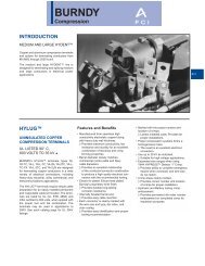
Figure 1 - Field-of-View (Horizontal)<br />
(cat. nos. RS110 and PS110) (cat. no. PS200)<br />
50 ft.<br />
40 ft.<br />
30 ft.<br />
20 ft.<br />
10 ft.<br />
0 ft. 110˚<br />
10 ft.<br />
20 ft.<br />
30 ft.<br />
40 ft.<br />
50 ft.<br />
50 feet<br />
Figure 2 - Field-of-View (Vertical)<br />
0 ft.<br />
3<br />
50 ft.<br />
40 ft.<br />
30 ft.<br />
20 ft.<br />
10 ft.<br />
0 ft. 200˚<br />
10 ft.<br />
20 ft.<br />
30 ft.<br />
40 ft.<br />
50 ft.<br />
50 feet<br />
40 ft.<br />
MaX.<br />
10 ft.<br />
50 ft.<br />
MaX.
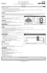
InStallatIOn InStRuctIOnS<br />
WaRnInG: TO BE INSTALLED AND/OR USED IN ACCORDANCE WITH<br />
APPROPRIATE ELECTRICAL CODES AND REGULATIONS.<br />
WaRnInG: IF YOU ARE NOT SURE ABOUT ANY PART OF THESE<br />
INSTRUCTIONS, CONSULT A QUALIFIED ELECTRICIAN.<br />
WaRnInG: TO AVOID OVERHEATING AND POSSIBLE DAMAGE TO THIS<br />
DEVICE AND OTHER EQUIPMENT, DO nOt INSTALL TO CONTROL A<br />
RECEPTACLE, A MOTOR- OR A TRANSFORMER-OPERATED APPLIANCE<br />
OTHER THAN APPROPRIATE LOW-VOLTAGE OR FLUORESCENT<br />
LIGHTING.<br />
WaRnInG: ALTHOUGH WEATHER-RESISTANT, THE SENSOR SHOULD<br />
NOT BE EXPOSED TO DIRECT PRECIPITATION OR ROOF RUNOFF<br />
SINCE PROLONGED EXPOSURE MAY DAMAGE THE DEVICE.<br />
OtHER cautIOnS anD nOtES:<br />
1. DISCONNECT POWER WHEN SERVICING FIXTURE OR CHANGING<br />
BULBS.<br />
2. USE THIS DEVICE WITH COPPER OR COPPER CLAD WIRE ONLY.<br />
WITH ALUMINUM WIRE USE DEVICES MARKED CO/ALR OR CU/AL<br />
ONLY.<br />
3. MOUNT ON STABLE SURFACE AND NOT ABOVE LAMPS OR NEAR AIR<br />
VENTS.<br />
4. DO nOt AIM SENSOR INTO DIRECT SUNLIGHT OR REFLECTED LIGHT<br />
FROM BRIGHT SURFACES.<br />
tO InStall:<br />
1. WaRnInG: TO AVOID FIRE, SHOCK, OR DEATH: tuRn OFF POWER<br />
AT CIRCUIT BREAKER OR FUSE AND TEST THAT THE POWER IS OFF<br />
BEFORE WIRING.<br />
2a. For Installations if there is an existing switch to the lighting<br />
fixture and nO Manual Overri<strong>de</strong> Switch is <strong>de</strong>sired (refer to WIRInG<br />
DIaGRaMS 1 & 2): Remove the switch from its wall box and disconnect<br />
the leads from the terminal screws. Twist the exposed ends tightly<br />
together and screw on wire connector making sure that no bare wire<br />
shows below the connector. Secure the wire connector with electrical<br />
tape. Cover the wall box with a blank wallplate.<br />
2B. For Installations if a Manual Overri<strong>de</strong> Switch is <strong>de</strong>sired (refer to<br />
WIRInG DIaGRaMS 3 & 4): In a retrofit application there may be an<br />
existing switch to the LOAD(S). By leaving this switch in the circuit, it is<br />
possible to shut OFF power to both the <strong>Sensor</strong> and the LOAD, if <strong>de</strong>sired.<br />
Choose the proper switch location.<br />
3. Choose the proper <strong>Sensor</strong> location. Install a NEMA rectangular weatherresistant<br />
fixture fitting at the <strong>Sensor</strong> location.<br />
4. Supply 120VAC power to the <strong>Sensor</strong> mounting location with 14AWG<br />
(minimum) BLACK and WHITE conductors with 600V/105°C insulation.<br />
If applicable, run 14AWG conductors with 600V/105°C insulation to the<br />
selected switch location on the LINE si<strong>de</strong> of the <strong>Sensor</strong>’s location. Refer to<br />
Switch Installation Instructions for mounting and wiring <strong>de</strong>tails.<br />
5. Screw the threa<strong>de</strong>d nipple on the <strong>Sensor</strong> arm into the center hole on the<br />
mounting plate.<br />
4<br />
aJuStE Y OPERacIOn<br />
La Prueba <strong>de</strong> Caminata se usa para verificar y ajustar el campo <strong>de</strong> visión que<br />
cubren los sensores. El sensor entra se pone en la Prueba <strong>de</strong> Caminata 30<br />
segundos <strong>de</strong>spués que se aplica energia a la unidad. Esto iniciará un período<br />
<strong>de</strong> prueba <strong>de</strong> aproximadamente 5 minutos. Durante estos 5 minutos, el sensor<br />
operará durante la luz <strong>de</strong> día y mantendrá la carga <strong>de</strong> iluminación encendida<br />
por 5 segundos <strong>de</strong>spués que cese el movimiento. Pruebe como sigue (vea<br />
Figura 4):<br />
1. Apunte el <strong>Sensor</strong> hacia el área que va a cubrir.<br />
2. ENCIENDA la energía a la unidad con el interruptor <strong>de</strong> circuito o fusible.<br />
3. Después que la energía está ENCENDIDA por lo menos 30 segundos,<br />
el sensor se pondrá automáticamente en el modo <strong>de</strong> PRUEBA DE<br />
CAMINATA.<br />
4. Párese fuera <strong>de</strong>l área cubierta, luego camine a través <strong>de</strong>l campo <strong>de</strong> visión<br />
hasta que la luz (ces) se ENCIENDA.<br />
5. Ajuste lo necesario la dirección <strong>de</strong> la cabeza <strong>de</strong>l <strong>Sensor</strong> para mejorar el<br />
área cubierta.<br />
6. Gire el Disco <strong>de</strong> Sensibilidad hacia la izquierda para disminuir la<br />
sensibilidad, lo cual pue<strong>de</strong> ser necesario si está monitoreando una área<br />
limitada o quiere hacer el <strong>Sensor</strong> menos sensible al viento, a hojas <strong>de</strong><br />
árboles y paso <strong>de</strong> animales. Girando el disco hacia la <strong>de</strong>recha ampliará el<br />
área cubierta.<br />
7. Repita los pasos <strong>de</strong>l 4 al 6 hasta que el área que <strong>de</strong>sea cubrir sea<br />
satisfactoria. Para realizar otra Prueba <strong>de</strong> Caminata <strong>de</strong>spués que la unidad<br />
ha regresado al modo automático, APAGUE la unidad por 15 segundos y<br />
ENCIENDALA otra vez. Vea el paso 3.<br />
8. Apriete las tuercas <strong>de</strong> seguridad y los tornillos <strong>de</strong>l brazo para asegurar la<br />
posición <strong>de</strong> la cabeza <strong>de</strong>l <strong>Sensor</strong>.<br />
9. Fije el Disco <strong>de</strong> Tiempo en el intervalo que <strong>de</strong>see. Girando el disco<br />
totalmente hacia la izquierda fija el tiempo en 20 segundos (<strong>de</strong>spués <strong>de</strong>l<br />
tiempo <strong>de</strong> espera y que no <strong>de</strong>tecte movimiento el <strong>Sensor</strong> APAGARA las<br />
luces). Girando el disco totalmente hacia la <strong>de</strong>recha fija el tiempo en<br />
15 minutos (<strong>de</strong>spués <strong>de</strong>l tiempo <strong>de</strong> espera y que no <strong>de</strong>tecte movimiento el<br />
<strong>Sensor</strong> APAGARA las luces).<br />
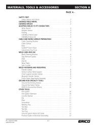
Figura 4 - Posición <strong>de</strong> Discos<br />
®<br />
SENS LIGHT TIME<br />
25<br />
Sólo los nos. <strong>de</strong> cat.<br />
PS110 and PS200 Only
4. Suministre energía <strong>de</strong> 120VCA en la ubicación <strong>de</strong>l <strong>Sensor</strong> con conductores<br />
Blanco y Negro <strong>de</strong> 14AWG con aislante <strong>de</strong> 600V/105°C. Si es necesario,<br />
corra conductores <strong>de</strong> 14AWG con aislante <strong>de</strong> 600V/105°C a la ubicación<br />
seleccionada <strong>de</strong>l interruptor, al lado <strong>de</strong> LINEA don<strong>de</strong> está don<strong>de</strong> está el<br />
sensor. Vea las Instrucciones <strong>de</strong> Instalación <strong>de</strong>l Interruptor para <strong>de</strong>talles <strong>de</strong><br />
montaje y cableado.<br />
5. Atornille la perilla roscada en el brazo <strong>de</strong>l <strong>Sensor</strong> en el hueco <strong>de</strong>l centro <strong>de</strong><br />
la placa <strong>de</strong> pared.<br />
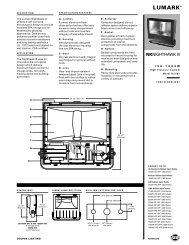
Figura 3 - Posición <strong>de</strong> Montaje<br />
correcto<br />
Incorrecto<br />
6. nOta: Asegure que la empaquetadura esté metida en la placa <strong>de</strong> Montaje<br />
<strong>de</strong>l <strong>Sensor</strong> antes <strong>de</strong> cablear.<br />
Conecte los conductores <strong>de</strong> acuerdo al DIAGRAMA DE CABLEADO y<br />
como sigue: Tuerce los hilos <strong>de</strong> cada conexión bien apretados y empújelos<br />
firmemente en el conector <strong>de</strong> alambres. Enrosque cada conector hacia la<br />
<strong>de</strong>recha, asegurando que no se vea ningún conductor <strong>de</strong>snudo <strong>de</strong>bajo <strong>de</strong>l<br />
conector. Asegure cada conector con cinta aislante.<br />
7. Coloque los conductores <strong>de</strong>ntro <strong>de</strong>l sujetador, luego monte la placa <strong>de</strong>l<br />
<strong>Sensor</strong> en el sujetador <strong>de</strong> montaje resistente a la intemperie, con los<br />
tornillos provistos.<br />
8. Después <strong>de</strong> colocar y ajustar el <strong>Sensor</strong> (ver Figura 4). Restablezca la<br />
corriente con el fusible o interruptor <strong>de</strong> circuito. la InStalacIOn ESta<br />
cOMPlEta.<br />
24<br />
Incorrecto<br />
Figure 3 - Mounting Position<br />
correct<br />
Incorrect<br />
6. nOtE: Ensure that Gasket is seated on <strong>Sensor</strong> Mounting Plate before<br />
wiring.<br />
Connect wires per appropriate WIRING DIAGRAM as follows: Twist<br />
strands of each lead tightly and, with circuit conductors, push firmly into the<br />
appropriate wire connector. Screw connector on clockwise making sure that<br />
no bare wire shows below the connector. Secure each wire connector with<br />
electrical tape.<br />
7. Carefully position the wires into the fixture, then mount the <strong>Sensor</strong> Mounting<br />
Plate onto the weather-resistant fixture fitting with the screws provi<strong>de</strong>d.<br />
8. After positioning and adjusting the sensor (refer to Figure 3), restore power<br />
at circuit breaker or fuse. InStallatIOn IS cOMPlEtE.<br />
aDJuStMEnt anD OPERatIOn<br />
The Walk Test is used to check and adjust the coverage pattern of the<br />
<strong>Sensor</strong>s. The <strong>Sensor</strong> will enter the WALK TEST mo<strong>de</strong> 30 seconds after power<br />
has been applied to the unit. This will initiate approximately a 5 minute WALK<br />
TEST period. During these 5 minutes, the sensor will operate in daylight and<br />
will keep its lighting load on for 5 seconds after motion ceases. Test as follows<br />
(refer to Figure 4):<br />
1. Aim the <strong>Sensor</strong> across the area it will be monitoring.<br />
2. Turn ON power to the unit at the fuse or circuit breaker.<br />
3. After power has been ON for at least 30 seconds, the sensor is<br />
automatically set for the WALK TEST mo<strong>de</strong>.<br />
5<br />
Incorrect
SENS LIGHT TIME<br />
4. Stand well outsi<strong>de</strong> the coverage area then start walking across the field-ofview<br />
until the light(s) turn ON.<br />
5. Adjust the aim of the <strong>Sensor</strong> head as necessary to improve coverage.<br />
6. Turn the Sensitivity Dial counter-clockwise to reduce the sensitivity, which<br />
may be necessary if monitoring a limited area or to make the <strong>Sensor</strong> less<br />
sensitive to wind, blown foliage and wan<strong>de</strong>ring animals. Turning the dial<br />
clockwise will maximize the <strong>Sensor</strong>’s coverage area.<br />
7. Repeat steps 4 through 6 until the coverage is satisfactory. To set another<br />
WALK TEST after the unit has returned to the automatic mo<strong>de</strong>, turn power<br />
to the unit OFF for at least 15 seconds and ON again. Refer to<br />
step 3.<br />
8. Tighten the locknuts and arm screws to secure the position of the <strong>Sensor</strong><br />
head.<br />
9. Set the Time Dial to the <strong>de</strong>sired interval. Turning the dial fully counterclockwise<br />
sets the time at 20 seconds (after the time <strong>de</strong>lay and motion is no<br />
longer <strong>de</strong>tected, the <strong>Sensor</strong> will turn the Load OFF). Turning the dial fully<br />
clockwise sets the time at 15 minutes, (after the time <strong>de</strong>lay and motion is no<br />
longer <strong>de</strong>tected, the <strong>Sensor</strong> will turn the Load OFF).<br />
Manual Overri<strong>de</strong> (if applicable):<br />
Figure 4 - Dial Positions<br />
®<br />
To turn the lights OFF, flip the switch to the OFF position.<br />
For Automatic operation, turn the switch ON for 30 seconds. The unit is now<br />
in WALK TEST mo<strong>de</strong>. To bypass the 5 minute WALK TEST mo<strong>de</strong>, flip the<br />
manual overri<strong>de</strong> switch on and off. This will cycle the power to the sensor and<br />
place the sensor into Automatic mo<strong>de</strong>.<br />
To keep the lights ON, flip the switch OFF and ON 2 times within a 2 to 3<br />
second period. To return to Automatic mo<strong>de</strong>, flip the switch OFF and ON once.<br />
For mo<strong>de</strong>ls PS110 and PS200 OnlY:<br />
ambient light level adjustment: The Ambient Light Level is the amount<br />
of light present. This setting will <strong>de</strong>termine at what level of ambient light the<br />
<strong>Sensor</strong> will turn ON when motion is <strong>de</strong>tected.<br />
6<br />
cat. nos. PS110<br />
and PS200 Only<br />
InStRuccIOnES DE InStalacIOn<br />
aDVERtEncIa: PARA INSTALARSE Y/O USARSE DE ACUERDO CON<br />
LOS CODIGOS ELECTRICOS Y NORMAS APROPIADAS.<br />
aDVERtEncIa: SI USTED NO ESTÁ SEGURO ACERCA DE ALGUNA<br />
DE LAS PARTES DE ESTAS INSTRUCCIONES, CONSULTE A UN<br />
ELECTRICISTA CALIFICADO.<br />
aDVERtEncIa: PARA EVITAR SOBRECALENTAMIENTO Y POSIBLE<br />
DAÑO A ESTE PRODUCTO Y OTROS EQUIPOS, nO lO INSTALE PARA<br />
CONTROLAR UN RECEPTACULO O ARTEFACTO OPERADO POR MOTOR<br />
O TRANSFORMADOR APARTE DE ILUMINACION APROPIADA DE BAJO<br />
VOLTAJE O FLUORESCENTE.<br />
aDVERtEncIa: APESAR QUE ES RESISTENTE AL AGUA, ESTE<br />
SENSOR NO SE DEBE EXPONER A PRECIPITACIONES DIRECTAS O<br />
CANALETAS DE SALIDA DE AGUA DEL TECHO, YA QUE EXPONERLO<br />
PROLONGADAMENTE PUEDE DAÑAR EL PRODUCTO.<br />
OtRaS PREcaucIOnES Y nOtaS:<br />
1. DESCONECTE LA ENERGIA CUANDO DE SERVICIO A LOS<br />
SUJETADORES DE LUZ O CAMBIE FOCOS.<br />
2. USE ESTE PRODUCTO SOLO CON CABLE DE COBRE O REVESTIDO<br />
DE COBRE. PARA CABLE DE ALUMINIO USE SOLO PRODUCTOS<br />
MARCADOS CON EL SIMBOLO CO/ALR O CU/AL.<br />
3. MONTE EN UNA SUPERFICIE ESTABLE Y NO SOBRE FOCOS O<br />
CORRIENTES DE AIRE.<br />
4. nO APUNTE EL SENSOR DIRECTAMENTE A LA LUZ SOLAR O AL<br />
REFLEJO DE LUZ DE SUPERFICIES BRILLANTES.<br />
PaRa InStalaR:<br />
1. aDVERtEncIa: PARA EVITAR DESCARGA ELECTRICA, FUEGO,<br />
O MUERTE, IntERRuMPa El PaSO DE EnERGIa MEDIANTE EL<br />
INTERRUPTOR DE CIRCUITO O FUSIBLE. ¡ASEGURESE QUE<br />
EL CIRCUITO NO ESTE ENERGIZADO ANTES DE INICIAR LA<br />
INSTALACION!<br />
2a. Para instalaciones don<strong>de</strong> ya existe un interruptor para la iluminación<br />
y no se <strong>de</strong>sea sobreponer un interruptor manual (ver los Diagramas<br />
<strong>de</strong> cableado 1 y 2): Saque el interruptor <strong>de</strong> la caja <strong>de</strong> pared y<br />
<strong>de</strong>sconecte los conductores <strong>de</strong> los tornillos terminales. Tuerce los hilos <strong>de</strong><br />
cada conexión bien apretados y empújelos firmemente en el conector <strong>de</strong><br />
alambres, asegurando que no se vea ningún conductor <strong>de</strong>snudo <strong>de</strong>bajo<br />
<strong>de</strong>l conector. Asegure cada conector con cinta aislante. Cubra la caja <strong>de</strong><br />
pared con una placa en blanco.<br />
2B. Para instalaciones don<strong>de</strong> se <strong>de</strong>sea sobreponer un interruptor<br />
manual (ver los Diagramas <strong>de</strong> cableado 3 y 4 ). En aplicaciones <strong>de</strong><br />
modificación, pue<strong>de</strong> existir un interruptor en las CARGA(S). Si <strong>de</strong>ja<br />
este interruptor en el circuito, es posible que éste APAGUE la energía<br />
en ambos el <strong>Sensor</strong> y en la CARGA, si se <strong>de</strong>sea. Elija una ubicación<br />
apropiada para el interruptor.<br />
3. Elija una ubicación apropiada para el <strong>Sensor</strong>. Instale el sujetador NEMA<br />
resistente a la intemperie en la ubicación <strong>de</strong>l <strong>Sensor</strong>.<br />
23
El no <strong>de</strong> cat. PS200 <strong>de</strong> leviton, cubre 200° con compensación <strong>de</strong><br />
temperatura a un rango <strong>de</strong> hasta <strong>de</strong> 15 m (50 pies) máximo cuando el sensor<br />
se monta a una altura <strong>de</strong> 3 m (10 pies). La unidad provee supresión <strong>de</strong><br />
sobretensión e inmunidad <strong>de</strong> RFI. También tiene un ajuste <strong>de</strong> nivel <strong>de</strong> luz <strong>de</strong><br />
ambiente que le permite una operación bajo un amplio rango <strong>de</strong> iluminación.<br />
Pue<strong>de</strong> conmutar cargas <strong>de</strong> iluminación incan<strong>de</strong>scente hasta 1000W.<br />
Los <strong>Sensor</strong>es <strong>de</strong> Ocupación están diseñados para su uso en exteriores,<br />
pero también se pue<strong>de</strong> usar en interiores. Está a<strong>de</strong>cuado especialmente<br />
para montarse en pare<strong>de</strong>s exteriores utilizando una caja rectangular NEMA<br />
resistente a la intemperie.<br />
Los Nos. <strong>de</strong> Cat. RS110, PS110 y PS200 están listados por UL, certificados<br />
por CSA y cumplen con los requerimientos <strong>de</strong>l Título 24 <strong>de</strong> California.<br />
Figura 1 - campo <strong>de</strong> Visión (Horizontal)<br />
(no. <strong>de</strong> cat. RS110 and PS110) (no. <strong>de</strong> cat. PS200)<br />
15 m<br />
12 m<br />
9 m<br />
6 m<br />
3 m<br />
0 110˚<br />
3 m<br />
6 m<br />
9 m<br />
12 m<br />
15 m<br />
15 metros<br />
15 m<br />
12 m<br />
9 m<br />
6 m<br />
3 m<br />
0 200˚<br />
3 m<br />
6 m<br />
9 m<br />
12 m<br />
15 m<br />
15 mètres<br />
Figura 2 - campo <strong>de</strong> Visión (Vertical)<br />
0<br />
22<br />
12 m<br />
max.<br />
3 m<br />
15 m<br />
max.<br />
Set the Light Dial to the <strong>de</strong>sired interval. Turning the dial fully counterclockwise<br />
sets the light level to the minimum of 5 LUX. Turning the dial fully<br />
clockwise sets the light level to the maximum of 1000 LUX.<br />
temperature compensation: These mo<strong>de</strong>ls have a built-in automatic<br />
temperature compensator. This compensator automatically adjusts the<br />
sensitivity (higher or lower) <strong>de</strong>pending on the ambient outdoor temperature.<br />
tROuBlESHOOtInG GuIDE<br />
nOtE: Each <strong>Sensor</strong> is manufactured using strict quality control procedure and<br />
rigorous testing before leaving the factory. If the unit performs erratically, follow<br />
the steps below to <strong>de</strong>termine the cause.<br />
• Lights do not turn ON<br />
- Check to see that power is ON at circuit breaker or fuse.<br />
- Ensure that bulbs/tubes are good.<br />
- Ensure wiring is correct per Wiring Diagrams.<br />
- Ensure that <strong>Sensor</strong> is aimed properly.<br />
- Check to see that lens is clean and unobstructed.<br />
- Ensure any switch on the fixture is ON.<br />
• Lights turn ON and OFF too quickly<br />
- Ensure that no source of heat (i.e., lamps or vents) is too close to the<br />
<strong>Sensor</strong>.<br />
- Ensure that light is not reflecting back towards the <strong>Sensor</strong> from white<br />
or reflective surfaces.<br />
- <strong>Sensor</strong> may be more sensitive in winter than summer, due to sharper<br />
contrast in Infrared.<br />
• Lights do not turn OFF<br />
- Check to see that time <strong>de</strong>lay setting is at the minimum.<br />
- Ensure that unit is firmly mounted on a stable surface that does not<br />
sway in the wind.<br />
- Ensure that <strong>Sensor</strong> is not aimed at swaying tree branches, a body of<br />
water, air-conditioning or heater vents.<br />
- Ensure that unit is not in the manual overri<strong>de</strong> mo<strong>de</strong> by turning power<br />
OFF for at least 5 seconds, then ON.<br />
- If there is a switch in the circuit, make sure that it is in the proper<br />
position.<br />
- Check to see that the line voltage has not dropped below 100VAC (for<br />
120VAC <strong>de</strong>vices) due to the operation of a large appliance on the circuit.<br />
• Lights turn ON in storms<br />
Rain, snow and high winds can create changes in temperature that may<br />
trigger the <strong>Sensor</strong>. False triggering can be minimized by installing the<br />
<strong>Sensor</strong> in a protected location and by also turning down the sensitivity<br />
control.<br />
For additional information call leviton’s technical Support line.<br />
7
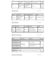
Wiring Diagram 1 - cat. nos. RS110-10, PS110-10 and PS200-10<br />
Hot (Black)<br />
line<br />
120Vac, 60Hz<br />
neutral (White)<br />
Hot (Black)<br />
line<br />
120Vac, 60Hz<br />
neutral (White)<br />
Hot (Black)<br />
line<br />
120Vac, 60Hz<br />
neutral (White)<br />
White<br />
Blue<br />
Blue<br />
Black<br />
Wiring Diagram 2 - cat. nos. RS110-1F,<br />
PS110-1F and PS200-1F<br />
Switch<br />
White<br />
Blue<br />
Blue<br />
lamphol<strong>de</strong>r<br />
Wires<br />
Black<br />
White<br />
Black<br />
Blue<br />
Blue<br />
White<br />
White<br />
Black<br />
lamphol<strong>de</strong>r<br />
Wires<br />
Black<br />
<strong>Sensor</strong><br />
Black<br />
load White<br />
<strong>Sensor</strong><br />
<strong>Sensor</strong><br />
Wiring Diagram 3 - cat. nos. RS110-10, PS110-10 and PS200-10<br />
8<br />
Black<br />
load<br />
White<br />
caRactERIStIcaS<br />
• Campo <strong>de</strong> visión ajustable hasta un máximo <strong>de</strong> 200˚ (PS200) o<br />
110˚ (PS110/RS110) usando rejillas externas<br />
• Sensibilidad, luz y tiempo ajustables (PS110/PS200)<br />
• Sensibilidad y tiempo ajustable (RS110)<br />
• Supresor <strong>de</strong> sobretensión, inmunidad RFI y compensación <strong>de</strong> temperatura<br />
(PS110/PS200)<br />
• Cuerpo resistente al agua<br />
ESPEcIFIcatIOn<br />
capacidad: 120 Vca, 60 Hz<br />
consumo <strong>de</strong> Energía: 4W<br />
nos. <strong>de</strong> cat.<br />
PS110-10 (sin portalámpara)<br />
PS110-1F (con portalámpara)<br />
PS200-10 (sin portalámpara)<br />
PS200-1F (con portalámpara)<br />
Incan<strong>de</strong>scente: 1000W @ 120V<br />
nos. <strong>de</strong> cat.<br />
RS110-10 (sin portalámpara)<br />
RS110-1F (con portalámpara)<br />
Incan<strong>de</strong>scente: 500W @ 120V<br />
DEScRIPcIOn<br />
La familia <strong>de</strong> los <strong>Sensor</strong>es <strong>de</strong> Ocupación para Exteriores consiste <strong>de</strong> tres<br />
mo<strong>de</strong>los, cada uno <strong>de</strong> los cuales usan tecnología <strong>de</strong> sensibilidad infrarroja,<br />
tienen sensibilidad <strong>de</strong> <strong>de</strong>tección y ajustes <strong>de</strong> tiempo <strong>de</strong> Encendido. Los<br />
tres mo<strong>de</strong>los tienen capacidad <strong>de</strong> tres modos <strong>de</strong> operación cuando ellos<br />
son alimentados a través <strong>de</strong> un interruptor; Automático (normal), Prueba y<br />
Continuo (las luces siempre Encendidas). Cuando se conectan directamente<br />
a la corriente sin interruptor, sólo operan en el modo Automático. Estos<br />
<strong>Sensor</strong>es <strong>de</strong> Ocupación para Exteriores están diseñados para ser montados<br />
a una altura entre 2.4 m y 3 m (8 a 10 pies) y tienen niveles máximos<br />
similares, aunque los patrones <strong>de</strong> <strong>de</strong>tección y el campo <strong>de</strong> visión varían<br />
<strong>de</strong> acuerdo con el número <strong>de</strong>l mo<strong>de</strong>lo. Cada sensor tiene un sensor y un<br />
interruptor incorporado en una unidad y se instalan como parte <strong>de</strong> un circuito<br />
<strong>de</strong> iluminación. Este ENCIENDE las luces cuando siente movimiento por<br />
un cuerpo que emite calor <strong>de</strong>ntro su campo <strong>de</strong> visión. También las APAGA<br />
<strong>de</strong>spués que no hay movimiento <strong>de</strong>ntro su campo <strong>de</strong> visión y termina el<br />
tiempo fijado por el usuario.<br />
El no <strong>de</strong> cat. RS110 <strong>de</strong> leviton, provee la función básica <strong>de</strong> anochecer y<br />
amanecer. Tiene un campo <strong>de</strong> visión <strong>de</strong> 110° y un rango <strong>de</strong> <strong>de</strong>tección <strong>de</strong><br />
15 m (50 pies) máximo cuando la cabeza <strong>de</strong>l sensor se monta a una altura<br />
<strong>de</strong> 3 m (10 pies). Pue<strong>de</strong> conmutar cargas <strong>de</strong> iluminación incan<strong>de</strong>scente hasta<br />
500W.<br />
El no <strong>de</strong> cat. PS110 <strong>de</strong> leviton, cubre 110° con compensación <strong>de</strong><br />
temperatura a un rango <strong>de</strong> hasta <strong>de</strong> 15 m (50 pies) máximo cuando el sensor<br />
se monta a una altura <strong>de</strong> 3 m (10 pies). La unidad provee supresión <strong>de</strong><br />
sobretensión e inmunidad <strong>de</strong> RFI. También tiene un ajuste <strong>de</strong> nivel <strong>de</strong> luz <strong>de</strong><br />
ambiente que le permite una operación bajo un rango amplio <strong>de</strong> iluminación.<br />
Pue<strong>de</strong> conmutar cargas <strong>de</strong> iluminación incan<strong>de</strong>scente hasta 1000W.<br />
21
Español<br />
tabla <strong>de</strong> contenido<br />
SEccIOn PaGIna<br />
CARACTERISTICAS ..................................................21<br />
ESPECIFICACIONES ................................................21<br />
DESCRIPCION ...........................................................21<br />
INSTRUCCIONES DE INSTALACION .......................23<br />
ADJUSTE Y OPERACION .........................................25<br />
GUIA DE SOLUCION DE PROBLEMAS ....................26<br />
lista <strong>de</strong> Figuras<br />
SEctIOn PaGE<br />
Figura 1 - Campo <strong>de</strong> Visión (Horizontal) ....................22<br />
Figura 2 - Campo <strong>de</strong> Visión (Vertical) .........................22<br />
Figura 3 - Posición <strong>de</strong> Montaje ...................................24<br />
Figure 4 - Posición <strong>de</strong> Discos .....................................25<br />
Diagramas <strong>de</strong> Cableado .............................................28<br />
20<br />
Hot (Black)<br />
line<br />
120Vac, 60Hz<br />
neutral (White)<br />
Wiring Diagram 4 - cat. nos. RS110-1F,<br />
PS110-1F and PS200-1F<br />
Switch<br />
lIMItED FIVE YEaR WaRRantY anD EXcluSIOnS<br />
<strong>Leviton</strong> warrants to the original consumer purchaser and not for the benefit of anyone<br />
else that this product at the time of its sale by <strong>Leviton</strong> is free of <strong>de</strong>fects in materials<br />
and workmanship un<strong>de</strong>r normal and proper use for five years from the purchase<br />
date. <strong>Leviton</strong>’s only obligation is to correct such <strong>de</strong>fects by repair or replacement, at<br />
its option, if within such five year period the product is returned prepaid, with proof of<br />
purchase date, and a <strong>de</strong>scription of the problem to leviton Manufacturing co., Inc.,<br />
att: Quality assurance Department, 59-25 little neck Parkway, little neck, new<br />
York 11362-2591. This warranty exclu<strong>de</strong>s and there is disclaimed liability for labor for<br />
removal of this product or reinstallation. This warranty is void if this product is installed<br />
improperly or in an improper environment, overloa<strong>de</strong>d, misused, opened, abused,<br />
or altered in any manner, or is not used un<strong>de</strong>r normal operating conditions or not in<br />
accordance with any labels or instructions. there are no other or implied warranties<br />
of any kind, including merchantability and fitness for a particular purpose, but if<br />
any implied warranty is required by the applicable jurisdiction, the duration of any such<br />
implied warranty, including merchantability and fitness for a particular purpose, is limited<br />
to five years. leviton is not liable for inci<strong>de</strong>ntal, indirect, special, or consequential<br />
damages, including without limitation, damage to, or loss of use of, any equipment,<br />
lost sales or profits or <strong>de</strong>lay or failure to perform this warranty obligation. The<br />
remedies provi<strong>de</strong>d herein are the exclusive remedies un<strong>de</strong>r this warranty, whether based<br />
on contract, tort or otherwise.<br />
For technical assistance call:<br />
1-800-824-3005 (u.S.a. Only)<br />
www.leviton.com<br />
9<br />
lamphol<strong>de</strong>r<br />
Wires<br />
Black<br />
White<br />
Black<br />
Blue<br />
Blue<br />
White<br />
White<br />
Black<br />
lamphol<strong>de</strong>r<br />
Wires<br />
<strong>Sensor</strong>
Français<br />
table <strong>de</strong>s matières<br />
SEctIOn PaGE<br />
Caractéristiques générales .........................................11<br />
Caractéristiques techniques .......................................11<br />
Description ..................................................................11<br />
Directives d'installation ...............................................13<br />
Réglage et fonctionnement .........................................15<br />
Diagnostic <strong>de</strong>s anomalies ...........................................16<br />
liste <strong>de</strong>s Figures<br />
SEctIOn PaGE<br />
Figure 1 - Champ <strong>de</strong> vision (vue plongeante) ............12<br />
Figure 2 - Champ <strong>de</strong> vision (vue latérale) ..................12<br />
Figure 3 - Montage .....................................................14<br />
Figure 4 - Disposition <strong>de</strong>s boutons .............................15<br />
Schémas <strong>de</strong> câblage ..................................................18<br />
10<br />
actif (noir)<br />
ligne<br />
120 V c.a., 60 Hz<br />
neutre (Blanc)<br />
Schéma <strong>de</strong> câblage 4 - n OS <strong>de</strong> cat. RS110-1F,<br />
PS110-1F et PS200-1F<br />
Interrupteur<br />
Fils <strong>de</strong> douille<br />
noir<br />
Blanc<br />
noir<br />
Bleu<br />
Bleu<br />
Blanc<br />
Blanc<br />
noir<br />
Fils <strong>de</strong> douille<br />
<strong>Détecteur</strong><br />
EXcluSIOnS Et GaRantIE lIMItÉE DE 5 anS<br />
<strong>Leviton</strong> garantit au premier acheteur, et uniquement au crédit du dit acheteur, que ce<br />
produit ne présente ni défauts <strong>de</strong> fabrication ni défauts <strong>de</strong> matériaux au moment <strong>de</strong> sa<br />
vente par <strong>Leviton</strong>, et n’en présentera pas tant qu’il est utilisé <strong>de</strong> façon normale et adéquate,<br />
pendant une pério<strong>de</strong> <strong>de</strong> 5 ans suivant la date d’achat. La seule obligation <strong>de</strong> <strong>Leviton</strong><br />
sera <strong>de</strong> corriger les dits défauts en réparant ou en remplaçant le produit défectueux si ce<br />
<strong>de</strong>rnier est retourné port payé, accompagné d’une preuve <strong>de</strong> la date d’achat, avant la fin<br />
<strong>de</strong> la dite pério<strong>de</strong> <strong>de</strong> 5 ans, à la Manufacture leviton du canada limitée, au soin du<br />
service <strong>de</strong> l’assurance Qualité, 165 boul. Hymus, Pointe-claire, (Québec), canada<br />
H9R 1E9. Par cette garantie, <strong>Leviton</strong> exclut et décline toute responsabilité envers les<br />
frais <strong>de</strong> main d’oeuvre encourus <strong>pour</strong> retirer et réinstaller le produit. Cette garantie sera<br />
nulle et non avenue si le produit est installé incorrectement ou dans un environnement<br />
inadéquat, s’il a été surchargé, incorrectement utilisé, ouvert, employé <strong>de</strong> façon abusive<br />
ou modifié <strong>de</strong> quelle que manière que ce soit, ou s’il n’a été utilisé ni dans <strong>de</strong>s conditions<br />
normales ni conformément aux directives ou étiquettes qui l’accompagnent. aucune<br />
autre garantie, explicite ou implicite, y compris celle <strong>de</strong> qualité marchan<strong>de</strong> et <strong>de</strong><br />
conformité au besoin, n’est donnée, mais si une garantie implicite est requise en vertu<br />
<strong>de</strong> lois applicables, la dite garantie implicite, y compris la garantie <strong>de</strong> qualité marchan<strong>de</strong><br />
et <strong>de</strong> conformité au besoin, est limitée à une durée <strong>de</strong> 5 ans. leviton décline toute<br />
responsabilité envers les dommages indirects, particuliers ou consécutifs, incluant,<br />
sans restriction, la perte d’usage d’équipement, la perte <strong>de</strong> ventes ou les manques<br />
à gagner, et tout dommage-intérêt découlant du délai ou du défaut <strong>de</strong> l’exécution<br />
<strong>de</strong>s obligations <strong>de</strong> cette garantie. Seuls les recours stipulés dans les présentes, qu’ils<br />
soient d’ordre contractuel, délictuel ou autre, sont offerts en vertu <strong>de</strong> cette garantie<br />
Pour toute ai<strong>de</strong> technique, composer le :<br />
1 800 405-5320 (canada seulement)<br />
www.leviton.com<br />
19
actif (noir)<br />
lIgne<br />
120 V c.a., 60 Hz<br />
neutre (blanc)<br />
actif (noir)<br />
ligne<br />
120 V c.a., 60 Hz<br />
neutre (Blanc)<br />
actif (noir)<br />
ligne<br />
120 V c.a., 60 Hz<br />
Schéma <strong>de</strong> câblage 1 - n OS <strong>de</strong> cat. RS110-10,<br />
PS110-10 et PS200-10<br />
Blanc<br />
noir<br />
Bleu<br />
Bleu<br />
noir<br />
Blanc<br />
noir<br />
Bleu<br />
Bleu<br />
Blanc<br />
<strong>Détecteur</strong><br />
Schéma <strong>de</strong> câblage 2 - n OS <strong>de</strong> cat. RS110-1F,<br />
PS110-1F et PS200-1F<br />
Fils <strong>de</strong> douille<br />
Blanc<br />
noir<br />
Fils <strong>de</strong> douille<br />
Schéma <strong>de</strong> câblage 3 - n OS <strong>de</strong> cat. RS110-10,<br />
PS110-10 et PS200-10<br />
neutre (Blanc)<br />
Interrupteur<br />
Blanc<br />
18<br />
noir<br />
Bleu<br />
Bleu<br />
noir<br />
charge Blanc<br />
<strong>Détecteur</strong><br />
<strong>Détecteur</strong><br />
noir Blanc<br />
charge<br />
•<br />
•<br />
•<br />
•<br />
•<br />
CARACTÉRISTIQUES GÉNÉRALES<br />
Champ <strong>de</strong> vision entièrement réglable, pouvant atteindre 200° (PS200) ou<br />
110° (PS110/RS110), au moyen d’obturateurs externes<br />
Réglages <strong>de</strong> la sensibilité, <strong>de</strong> l’intensité ambiante et du délai d’éteinte<br />
(PS110/PS200)<br />
Réglage <strong>de</strong> la sensibilité et du délai d’éteinte (RS110)<br />
Limitation <strong>de</strong>s surtensions transitoires, immunité au bruit radioélectrique et<br />
compensation <strong>de</strong> la température (PS110/PS200)<br />
Boîtier hydrorésistant<br />
CARACTÉRISTIQUES TECHNIQUES<br />
Valeurs nominales : 120 V c.a., 60 Hz<br />
consommation <strong>de</strong> 4 W<br />
nos <strong>de</strong> cat.<br />
PS110-10 (sans douille)<br />
PS110-1F (avec douille)<br />
PS200-10 (sans douille)<br />
PS200-1F (avec douille)<br />
À incan<strong>de</strong>scence : 1 000 W à 120 V<br />
nos <strong>de</strong> cat.<br />
RS110-10 (sans douille)<br />
RS110-1F (avec douille)<br />
À incan<strong>de</strong>scence : 500 W à 120 V<br />
DEScRIPtIOn<br />
La gamme <strong>de</strong>s détecteurs <strong>de</strong> <strong>mouvements</strong> <strong>pour</strong> l’extérieur <strong>de</strong> <strong>Leviton</strong> se<br />
compose <strong>de</strong> trois modèles, lesquels fonctionnent tous au moyen <strong>de</strong> la<br />
technologie <strong>de</strong> détection à infrarouge; ils sont tous dotés <strong>de</strong> réglages <strong>de</strong> la<br />
sensibilité et du délai d’éteinte. Raccordé à un interrupteur, chacun <strong>de</strong> ces trois<br />
modèles peut être utilisé en trois mo<strong>de</strong>s distincts : «automatique» (normal),<br />
«vérification» et «continu» (luminaires toujours allumés). D’un autre côté,<br />
s’ils sont raccordés directement à l’alimentation (aucun interrupteur), ils ne<br />
peuvent fonctionner qu’en mo<strong>de</strong> automatique. Ces dispositifs sont conçus<br />
<strong>pour</strong> être installés à une hauteur variant entre 2,5 et 3 mètres (8 à 10 pieds),<br />
et procurent tous une portée maximale semblable, bien que la disposition <strong>de</strong><br />
la zone <strong>de</strong> détection et du champ <strong>de</strong> vision peut varier selon le modèle utilisé.<br />
Chacun <strong>de</strong> ces détecteurs est doté d’un commutateur et d’un capteur intégrés.<br />
Raccordés à un circuit d’éclairage, ces dispositifs allument les luminaires<br />
lorsqu’ils détectent les <strong>mouvements</strong> d’un corps émettant <strong>de</strong> la chaleur dans<br />
leur champ <strong>de</strong> vision, et les éteignent ensuite, une fois le délai d’éteinte (réglé<br />
par l’utilisateur) écoulé, et les <strong>mouvements</strong> arrêtés.<br />
Le no <strong>de</strong> cat. RS110 <strong>de</strong> <strong>Leviton</strong> offre <strong>de</strong>s fonctions <strong>de</strong> base entre le<br />
crépuscule et l’aube. Lorsque sa tête <strong>de</strong> détection est installée à une hauteur<br />
<strong>de</strong> 3 mètres (10 pi), il permet d’obtenir un champ <strong>de</strong> vision <strong>de</strong> 110°, lui donnant<br />
une portée <strong>de</strong> détection <strong>de</strong> 15 mètres (50 pi). Il effectue la commutation <strong>de</strong><br />
charges d’éclairage à incan<strong>de</strong>scence pouvant atteindre 500 W.<br />
Le no <strong>de</strong> cat. PS110 <strong>de</strong> <strong>Leviton</strong> procure une zone <strong>de</strong> détection <strong>de</strong> 110° (avec<br />
compensation <strong>de</strong> température) dont la portée peut atteindre 15 mètres (50 pi)<br />
s’il est installé à une hauteur <strong>de</strong> 3 mètres (10 pi) du sol. Ce dispositif est doté<br />
11
<strong>de</strong> mécanismes <strong>de</strong> limitation <strong>de</strong>s surtensions transitoires et d’immunité au<br />
bruit radioélectrique. Il est en outre muni d’un réglage <strong>de</strong> l’éclairage ambiant<br />
qui lui permet <strong>de</strong> fonctionner dans toute une variété <strong>de</strong> conditions lumineuses.<br />
Il effectue la commutation <strong>de</strong> charges d’éclairage à incan<strong>de</strong>scence pouvant<br />
atteindre 1 000 W.<br />
Le no <strong>de</strong> cat. PS200 <strong>de</strong> <strong>Leviton</strong>, quant à lui, procure une zone <strong>de</strong> détection <strong>de</strong><br />
200° (avec compensation <strong>de</strong> température) dont la portée peut atteindre<br />
15 mètres (50 pi) lorsqu’il est installé à une hauteur <strong>de</strong> 3 mètres (10 pi)<br />
du sol. Lui aussi est doté <strong>de</strong> mécanismes <strong>de</strong> limitation <strong>de</strong>s surtensions<br />
transitoires et d’immunité au bruit radioélectrique, et est muni d’un réglage <strong>de</strong><br />
l’éclairage ambiant qui lui permet <strong>de</strong> fonctionner dans toute une variété <strong>de</strong><br />
conditions lumineuses. Il effectue la commutation <strong>de</strong> charges d’éclairage à<br />
incan<strong>de</strong>scence pouvant atteindre 1 000 W.<br />
Bien que ces détecteurs <strong>de</strong> <strong>mouvements</strong> soient conçus <strong>pour</strong> l’extérieur, on<br />
peut aussi les utiliser à l’intérieur. À l’extérieur, on recomman<strong>de</strong> <strong>de</strong> les installer<br />
au mur, dans <strong>de</strong>s boîtes rectangulaires intempérisées <strong>de</strong> type NEMA.<br />
Les détecteurs RS110, PS110 et PS200 sont homologués UL et CSA (et<br />
conformes aux normes américaines California Title 24).<br />
Figure 1 - champ <strong>de</strong> vision (vue plongeante)<br />
(n OS <strong>de</strong> cat. RS110 et PS110)<br />
15 m<br />
12 m<br />
9 m<br />
6 m<br />
3 m<br />
0 110˚<br />
3 m<br />
6 m<br />
9 m<br />
12 m<br />
15 m<br />
15 mètres<br />
0<br />
(n O <strong>de</strong> cat. PS200)<br />
15 m<br />
12 m<br />
9 m<br />
6 m<br />
3 m<br />
0 200˚<br />
3 m<br />
6 m<br />
9 m<br />
12 m<br />
15 m<br />
15 mètres<br />
Figure 2 - champ <strong>de</strong> vision (vue latérale)<br />
12<br />
12 m<br />
max.<br />
3 m<br />
15 m<br />
max.<br />
- s’assurer que le dispositif ne soit pas en mo<strong>de</strong> <strong>de</strong> comman<strong>de</strong> manuelle<br />
prioritaire en le mettant hors tension pendant 5 secon<strong>de</strong>s puis en le<br />
remettant sous tension;<br />
- s’assurer qu’en présence d’un interrupteur sur le circuit, ce <strong>de</strong>rnier soit<br />
dans la position appropriée;<br />
- s’assurer que la tension du circuit n’ait pas <strong>de</strong>scendu sous 100 V c.a.<br />
(<strong>pour</strong> les modèles <strong>de</strong> 120 V) en raison d’un gros appareil électrique<br />
alimenté sur le même circuit.<br />
• Les luminaires s’allument <strong>de</strong> façon intempestive pendant <strong>de</strong>s orages :<br />
- la pluie, la neige et les vents violents peuvent générer <strong>de</strong>s variations <strong>de</strong><br />
températures qui peuvent faire déclencher le détecteur. Pour éviter les<br />
déclenchements intempestifs, installer le détecteur à l’abri <strong>de</strong>s<br />
intempéries et en réduire la sensibilité.<br />
Pour <strong>de</strong> plus amples renseignements, on peut communiquer avec la<br />
ligne d’assistance technique <strong>de</strong> leviton.<br />
17
Pour passer en mo<strong>de</strong> automatique, mettre l’interrupteur SOUS TENSION;<br />
attendre 30 secon<strong>de</strong>s. Le dispositif se met d’abord en mo<strong>de</strong> d’ESSAI DE<br />
PÉNÉTRATION DE CHAMP. Si on veut omettre cette étape <strong>de</strong> 5 minutes, il<br />
suffit <strong>de</strong> commuter l’interrupteur <strong>de</strong> comman<strong>de</strong> manuelle prioritaire (hors/sous<br />
tension), ce qui mettra le détecteur en mo<strong>de</strong> automatique.<br />
Pour gar<strong>de</strong>r les luminaires continuellement allumés, mettre l’interrupteur<br />
HORS puis SOUS TENSION à <strong>de</strong>ux reprises et ce, dans l’espace <strong>de</strong> 2 à 3<br />
secon<strong>de</strong>s. Pour revenir au mo<strong>de</strong> automatique, remettre l’interrupteur HORS et<br />
SOUS TENSION une fois.<br />
Modèles PS110 et PS200 seulement :<br />
Réglage <strong>de</strong> l’intensité <strong>de</strong> l’éclairage ambiant : ce réglage permet <strong>de</strong><br />
déterminer l’intensité <strong>de</strong> l’éclairage naturel à laquelle le détecteur <strong>de</strong>vra<br />
allumer ses charges d’éclairage s’il détecte <strong>de</strong>s <strong>mouvements</strong>.<br />
Effectuer ce réglage au moyen du bouton prévu à cet effet. En tournant ce<br />
<strong>de</strong>rnier complètement vers la gauche, on obtient le réglage minimal, soit une<br />
intensité <strong>de</strong> 5 lux; en le tournant complètement vers la droite, on obtient le<br />
réglage maximal, soit <strong>de</strong> 1 000 lux.<br />
compensation <strong>de</strong> température : ces modèles sont dotés d’un compensateur<br />
<strong>de</strong> température automatique intégré, lequel règle automatiquement la<br />
sensibilité du détecteur (en l’augmentant ou en la diminuant) en fonction <strong>de</strong> la<br />
température ambiante.<br />
DIaGnOStIc DES anOMalIES<br />
REMaRQuE : chacun <strong>de</strong> ces modèles est fabriqué suivant les procédures<br />
<strong>de</strong> contrôle <strong>de</strong> qualité les plus strictes, et subit <strong>de</strong> rigoureuses mises à<br />
l’essai avant <strong>de</strong> quitter l’usine. Si le dispositif ne semble pas fonctionner<br />
correctement, suivre les étapes ci-<strong>de</strong>ssous <strong>pour</strong> en déterminer la cause.<br />
• Les luminaires ne s’allument pas :<br />
- vérifier si l’alimentation est sous tension au fusible ou au disjoncteur;<br />
- vérifier si les lampes sont en bon état;<br />
- vérifier si le dispositif est raccordé conformément au SCHÉMA DE<br />
CÂBLAGE approprié;<br />
- vérifier si le détecteur est correctement orienté;<br />
- s’assurer que la lentille soit propre et non obstruée;<br />
- s’assurer que l’interrupteur <strong>de</strong> comman<strong>de</strong> manuelle, le cas échéant,<br />
soit hors tension;<br />
- s’assurer que les commutateurs intégrés <strong>de</strong>s luminaires, le cas échéant,<br />
soient sous tension.<br />
• Les luminaires s’allument et s’éteignent trop rapi<strong>de</strong>ment :<br />
- s’assurer que le détecteur ne soit pas installé à proximité d’une source<br />
<strong>de</strong> chaleur (luminaires, bouche d’aération, etc.);<br />
- vérifier si le détecteur reçoit <strong>de</strong> la lumière reflétée par une surface<br />
blanche ou réfléchissante;<br />
- vérifier si le réglage <strong>de</strong> sensibilité est approprié à la saison (le détecteur<br />
risque d’être plus sensible l’hiver puisque le contraste <strong>de</strong>s températures<br />
est plus perceptible).<br />
• Les luminaires ne s’éteignent pas :<br />
- vérifier si le réglage du délai d’éteinte est trop élevé;<br />
- s’assurer que le dispositif soit fixé à une surface bien stable qui<br />
n’oscille pas avec le vent;<br />
- s’assurer que le détecteur ne soit pas orienté vers du branchage en<br />
mouvement, une étendue d’eau ou un évent <strong>de</strong> chauffage ou <strong>de</strong><br />
climatisation;<br />
16<br />
DIREctIVES D’InStallatIOn<br />
aVERtISSEMEnt : INSTALLER OU UTILISER CONFORMÉMENT AUX<br />
CODES DE L’ÉLECTRICITÉ EN VIGUEUR.<br />
aVERtISSEMEnt : À DÉFAUT DE BIEN COMPRENDRE LES<br />
PRÉSENTES DIRECTIVES, EN TOUT OU EN PARTIE, ON DOIT FAIRE<br />
APPEL À UN ÉLECTRICIEN QUALIFIÉ.<br />
aVERtISSEMEnt : POUR ÉVITER LA SURCHAUFFE OU<br />
L’ENDOMMAGEMENT ÉVENTUEL DE CE DISPOSITIF ET DES APPAREILS<br />
QUI LUI SONT RACCORDÉS, nE PaS L’INSTALLER POUR COMMANDER<br />
UNE PRISE OU UN APPAREIL MOTORISÉ OU À TRANSFORMATEUR;<br />
CE DISPOSITIF EST CONÇU POUR COMMANDER DES CHARGES<br />
D’ÉCLAIRAGE FLUORESCENTES OU À BASSE TENSION.<br />
aVERtISSEMEnt : BIEN QU’IL SOIT INTEMPÉRISÉ, LE DÉTECTEUR<br />
NE DOIT PAS êTRE DIRECTEMENT EXPOSÉ AUX PRÉCIPITATIONS OU<br />
À L’EAU D’ÉCOULEMENT D’UN TOIT; L’EXPOSITION PROLONGÉE À DE<br />
TELS ÉLÉMENTS PEUT CAUSER L’ENDOMMAGEMENT DU DISPOSITIF.<br />
MISES En GaRDE Et REMaRQuES cOMPlÉMEntaIRES :<br />
1. COUPER LE COURANT AVANT DE PROCÉDER À L’ENTRETIEN DES<br />
LUMINAIRES OU AU REMPLACEMENT DES LAMPES.<br />
2. N’UTILISER CE DISPOSITIF QU’AVEC DU FIL DE CUIVRE; EN<br />
PRÉSENCE DE FIL D’ALUMINIUM, UTILISER SEULEMENT LES<br />
DISPOSITIFS PORTANT LA MARQUE CU/AL OU CO/ALR.<br />
3. CE DISPOSITIF DOIT êTRE FIXÉ À UNE SURFACE STABLE; IL NE DOIT<br />
PAS êTRE INSTALLÉ AU-DESSUS D’UN LUMINAIRE OU À PROXIMITÉ<br />
D’UNE BOUCHE D’AÉRATION.<br />
4. LE DÉTECTEUR nE DOIt PaS êTRE ORIENTÉ VERS LE SOLEIL NI<br />
VERS DES SURFACES QUI RÉFLÉCHISSENT LA LUMIèRE.<br />
InStallatIOn :<br />
1. aVERtISSEMEnt : POUR ÉVITER LES RISQUES D’INCENDIE, DE<br />
CHOC ÉLECTRIQUE OU D’ÉLECTROCUTION, cOuPER lE cOuRant<br />
AU FUSIBLE OU AU DISJONCTEUR ET S’ASSURER QUE LE CIRCUIT<br />
SOIT BIEN COUPÉ AVANT DE PROCÉDER À L’INSTALLATION.<br />
2a. applications où un interrupteur existant comman<strong>de</strong> les luminaires et<br />
où la comman<strong>de</strong> manuelle prioritaire n’ESt PaS requise (se reporter<br />
aux ScHÉMaS DE cÂBlaGE 1 et 2) : retirer l’interrupteur existant <strong>de</strong><br />
sa boîte et retirer les fils <strong>de</strong>s bornes à vis. Torsa<strong>de</strong>r soli<strong>de</strong>ment ensemble<br />
les extrémités dénudées et enfoncer fermement dans <strong>de</strong>s marettes <strong>de</strong><br />
grosseur appropriée, en vissant ces <strong>de</strong>rnières et en s’assurant qu’aucun<br />
brin <strong>de</strong> cuivre ne dépasse; protéger au moyen <strong>de</strong> ruban isolant. Recouvrir<br />
la boîte murale d’une plaque d’obturation.<br />
2B. applications où un interrupteur <strong>de</strong> comman<strong>de</strong> manuelle prioritaire<br />
est prévu (se reporter aux ScHÉMaS DE cÂBlaGE 3 et 4) : s’il s’agit<br />
d’une installation rétroactive, il est possible que les charges d’éclairages<br />
soient commandées par <strong>de</strong>s interrupteurs. Si désiré, on peut laisser ces<br />
interrupteurs raccordés au circuit et les utiliser <strong>pour</strong> couper (ou rétablir)<br />
l’alimentation à la fois au détecteur et aux charges d’éclairage. Le cas<br />
échéant, déterminer l’emplacement <strong>de</strong> l’interrupteur.<br />
3. Déterminer l’emplacement du détecteur; y installer une boîte rectangulaire<br />
intempérisée <strong>de</strong> type NEMA <strong>pour</strong> luminaires.<br />
13
4. Raccor<strong>de</strong>r la boîte au circuit d’alimentation <strong>de</strong> 120 V c.a. au moyen <strong>de</strong><br />
conducteurs NOIR et BLANC <strong>de</strong> calibre 14 AWG, isolés (600 V / 105°) ou,<br />
le cas échéant, raccor<strong>de</strong>r <strong>de</strong> tels conducteurs entre l’interrupteur voulu<br />
et le côté LIGNE <strong>de</strong> la boîte où le détecteur sera installé. Se reporter aux<br />
directives <strong>de</strong> montage et <strong>de</strong> câblage fournies avec l’interrupteur.<br />
5. Visser le raccord fileté situé sur la tige du détecteur dans le trou central <strong>de</strong><br />
la plaque <strong>de</strong> montage.<br />
Figure 3 - Montage<br />
correct<br />
Incorrect<br />
6. REMaRQuE : s’assurer que le joint d’étanchéité soit correctement<br />
placé sur la plaque <strong>de</strong> montage du détecteur avant d’effectuer le<br />
câblage. Raccor<strong>de</strong>r les fils conformément au SCHÉMA DE CÂBLAGE<br />
approprié et <strong>de</strong> la façon suivante : torsa<strong>de</strong>r soli<strong>de</strong>ment ensemble les brins<br />
<strong>de</strong> chaque fil <strong>de</strong> sortie avec le conducteur correspondant et enfoncer<br />
fermement les raccords dans une marette <strong>de</strong> grosseur appropriée, en<br />
vissant cette <strong>de</strong>rnière et en s’assurant qu’aucun brin <strong>de</strong> cuivre ne dépasse.<br />
Protéger les raccords au moyen <strong>de</strong> ruban isolant.<br />
7. Disposer soigneusement les fils dans la boîte; fixer la plaque <strong>de</strong> montage du<br />
détecteur dans la boîte intempérisée au moyen <strong>de</strong>s vis fournies.<br />
8. Après avoir placé et orienté le détecteur <strong>de</strong> façon appropriée (Figure 4),<br />
rétablir le courant au fusible ou au disjoncteur; l’InStallatIOn ESt<br />
tERMInÉE.<br />
14<br />
Incorrect<br />
RÉGlaGE Et FOnctIOnnEMEnt<br />
On procè<strong>de</strong> à un ESSAI DE PÉNÉTRATION DU CHAMP (WALK TEST)<br />
<strong>pour</strong> vérifier et modifier au besoin la plage <strong>de</strong> couverture <strong>de</strong>s détecteurs. Le<br />
dispositif entre automatiquement dans ce mo<strong>de</strong> <strong>de</strong> vérification 30 secon<strong>de</strong>s<br />
après sa mise sous tension, et y reste pendant cinq minutes.<br />
Pendant ce délai, le détecteur ne se préoccupe pas <strong>de</strong> la luminosité ambiante<br />
et maintient ses charges allumées pendant cinq secon<strong>de</strong>s après l’absence <strong>de</strong><br />
<strong>mouvements</strong>. Procé<strong>de</strong>r alors <strong>de</strong> la manière suivante (figure 4) :<br />
1. Orienter le détecteur vers la zone qu’il doit surveiller.<br />
2. Alimenter le dispositif en rétablissant le courant au fusible ou au disjoncteur.<br />
3. Après un délai d’au moins 30 secon<strong>de</strong>s, le dispositif entre automatiquement<br />
en mo<strong>de</strong> d’ESSAI DE PÉNÉTRATION.<br />
4. Aller se placer hors <strong>de</strong> la zone <strong>de</strong> détection puis lentement y pénétrer<br />
jusqu’à ce que les luminaires s’allument.<br />
5. Réajuster l’orientation <strong>de</strong> la tête <strong>de</strong> détection <strong>de</strong> manière à obtenir le champ<br />
<strong>de</strong> vision requis.<br />
6. Le cas échéant, réduire la sensibilité <strong>de</strong> détection en tournant le bouton<br />
approprié vers la gauche; cela peut s’avérer nécessaire si la zone <strong>de</strong><br />
détection est petite ou si le détecteur est trop sensible aux <strong>mouvements</strong><br />
du vent, du feuillage ou d’animaux errants. Tourner le bouton vers la droite<br />
<strong>pour</strong> augmenter la zone <strong>de</strong> détection ou la sensibilité du détecteur.<br />
7. Reprendre les étapes 4 à 6 jusqu’à l’obtention <strong>de</strong> la couverture voulue. Pour<br />
refaire un essai <strong>de</strong> pénétration après que le dispositif soit revenu en mo<strong>de</strong><br />
automatique, mettre l'unité hors tension pendant au moins 15 secon<strong>de</strong>s,<br />
puis le remettre sous tension. Se reporter à l’étape 3.<br />
8. Serrer les contre-écrous ainsi que les vis <strong>de</strong> la tige afin d’assujettir<br />
soli<strong>de</strong>ment la tête <strong>de</strong> détection.<br />
9. Régler le délai d’éteinte à la valeur désirée. En tournant le bouton<br />
complètement vers la gauche, on obtient le réglage minimal <strong>de</strong> 20<br />
secon<strong>de</strong>s (délai suivant lequel le détecteur éteint les charges d’éclairage s’il<br />
ne capte plus <strong>de</strong> mouvement); en le tournant complètement vers la droite,<br />
on obtient le délai maximal, soit <strong>de</strong> 15 minutes.<br />
comman<strong>de</strong> manuelle prioritaire (selon l’application) :<br />
Pour éteindre les luminaires, mettre l’interrupteur en position HORS TENSION.<br />
Figure 4 - Disposition <strong>de</strong>s boutons<br />
®<br />
SENS LIGHT TIME<br />
15<br />
n OS <strong>de</strong> cat. PS110<br />
et PS200 seulement