Silofrit (d,e,f) - Bent Brandt WebShop
Silofrit (d,e,f) - Bent Brandt WebShop
Silofrit (d,e,f) - Bent Brandt WebShop

Create successful ePaper yourself
Turn your PDF publications into a flip-book with our unique Google optimized e-Paper software.
Smartline<br />
SILOFRIT<br />
Installationsanleitung<br />
Instructions pour l'installation<br />
Installation Instructions<br />
Technische Daten / Spécifications techniques / Specifications<br />
Typ<br />
Type<br />
Type<br />
ASF1<br />
BSF1<br />
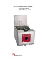
Aufstellung Tischmodell / Installation modèle de table / Installation table top model<br />
! & #<br />
Anschlusswert<br />
Raccordements<br />
Voltage<br />
230V 1N AC 50/60Hz<br />
230V 1N AC 50/60Hz<br />
1. Der Apparat darf nicht auf brennbarer<br />
Unterlage oder an brennbaren<br />
Wänden aufgestellt werden.<br />
2. Es muss seitlich mindestens<br />
10 cm Wandabstand eingehalten<br />
werden.<br />
3. Apparat aufstellen und durch Drehen<br />
der Stellfüsse ausnivellieren.<br />
4. Mehrere Geräte können mittels<br />
Schrauben (1) und (2) bündig aneinander<br />
geschraubt werden.<br />
Siehe Fig. 1.<br />
Leistung<br />
Puissance<br />
Power<br />
1000 W<br />
1000 W<br />
! & $ #<br />
Absicherung<br />
Fusible<br />
Fuse<br />
10 A<br />
10 A<br />
1. L'appareil ne peut pas être mis en<br />
service sur une surface ou près<br />
d'un mur combustible.<br />
2. L’espace latéral entre mur et appareil<br />
doit être au moins 10 cm.<br />
3. Poser l'appareil et vérifier qu'il soit<br />
de niveau au moyen des pieds<br />
réglables.<br />
4. Plusieurs appareils peuvent être<br />
vissés ensemble à fleur au moyen<br />
des vis (1) et (2). Voir fig. 1.<br />
Type ASF1<br />
Tisch/Table/<br />
Table top<br />
Kabel/Cable<br />
Typ/Type<br />
H05RN-F 3 x 1 mm2<br />
-<br />
SALVIS AG Dorfbachstrasse 2 CH-4663 Aarburg www.salvis.ch<br />
Type BSF1<br />
Einbau/Encastré/<br />
Built in<br />
1<br />
2<br />
Gewicht<br />
Poids<br />
Weight<br />
17.0 kg<br />
12.3 kg<br />
Fig. 1<br />
1. Make sure that unit is neither placed<br />
on a combustible surface nor<br />
placed against combustible walls.<br />
2. Leave at least 10 cm space laterally<br />
between wall and unit.<br />
3. Place unit in position and rotate<br />
adjustable feet to level it.<br />
4. Several units can be screwed flush<br />
together by means of screws (1)<br />
and (2). See Fig. 1.
349<br />
50<br />
20<br />
331<br />
9<br />
40<br />
6<br />
10<br />
62.5<br />
5<br />
3<br />
4<br />
113<br />
90<br />
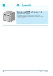
Einbauzeichnung<br />
Dessin de montage<br />
Mounting drawing<br />
13<br />
6<br />
40<br />
Ausschnitt für Instrumentenschild<br />
Découpure pour panneau de commande<br />
Cutout for control panel<br />
64<br />
572<br />
6<br />
Installation von Einbaumodellen,<br />
Typen: BBM 1; BKP 1; BKC 1; BSF 1; BFR 1;<br />
BGH 1; BCG 1; BKG 1<br />
352<br />
Installation des modèls encastrés,<br />
Types: BBM 1; BKP 1; BKC 1; BSF 1; BFR 1;<br />
BGH 1; BCG 1; BKG 1<br />
Ausschnitt für Gerät<br />
Découpure pour appareil<br />
Cutout for unit<br />
Installation of built in models,<br />
Types: BBM 1; BKP 1; BKC 1; BSF 1; BFR 1;<br />
BGH 1; BCG 1; BKG 1<br />
07.00
Einbaubeschrieb<br />
ACHTUNG: Das Gerät darf nicht in<br />
eine brennbare Umgebung eingebaut<br />
werden.<br />
Die Geräte können in CNS- oder<br />
Steinabdeckungen bis 40 mm Dicke<br />
eingebaut werden.<br />
Beim Einbau ist wie folgt vorzugehen:<br />
1. Nach Zeichnung, Einbauöffnungen<br />
ausschneiden und Befestigungslöcher<br />
bohren.<br />
2. Instrumentenschild erst durch die<br />
grosse, dann durch die kleine<br />
Öffnung nach aussen führen.<br />
3. Die zwei lose mitgelieferten Seitenpfosten<br />
(1) auf der Front positionieren<br />
und von innen mit den 4<br />
beiliegenden Schrauben (2) befestigen.<br />
4. Becken umgekehrt auf den Tisch<br />
legen. Im Auflageprofil zum Abdichten<br />
genügend hitzebeständiges<br />
Silikon oder Pactan (3) anbringen.<br />
5. Becken in Ausschnitt einbauen.<br />
6. Die 2 beiliegenden Verstärkungsschienen<br />
(6) über die Befestigungsbolzen<br />
legen. Dann mit beiliegenden<br />
6-kt Muttern (4) befestigen.<br />
7. Instrumentenschild an die zwei<br />
Seitenpfosten montieren. Zuerst<br />
oben, dann unten einhängen und<br />
anschrauben (5).<br />
Elektroanschluss<br />
- Angaben auf dem Typenschild<br />
beachten. Beim Tischgerät befindet<br />
es sich auf dem Aussenmantel.<br />
Beim Einbaugerät auf der Innenseite<br />
des Instrumentenschildes.<br />
- DIE GERÄTE DÜRFEN NUR VON<br />
AUTORISIERTEN ELEKTRO-<br />
INSTALLATEUREN ANGE-<br />
SCHLOSSEN WERDEN !<br />
- Die landesspezifischen und örtlichen<br />
Vorschriften müssen eingehalten<br />
werden.<br />
- Das Tischgerät wird mit 1.8 m<br />
Kabel ohne Stecker geliefert. Montage<br />
eines Netzsteckers und Anschluss<br />
über eine Steckdose oder<br />
Anschluss an einen Hauptschalter<br />
für allpolige Trennung mit einer<br />
Kontaktöffnung von min. 3 mm.<br />
- Steckdose in der Nähe des Gerätes<br />
plazieren. Der Stecker muss<br />
gut zugänglich sein.<br />
Description du montage<br />
ATTENTION: L’appareil ne doit pas<br />
être encastré dans un environnement<br />
combustible.<br />
L’installation des appareils peut être<br />
effectué dans des recouvrements en<br />
Inox ou en pierre épaisseur max.<br />
40 mm.<br />
Pour le montage, procéder de la manière<br />
suivante:<br />
1. Découper les ouvertures<br />
d’encastrement et percer les trous<br />
de fixation selon le dessin.<br />
2. Passer la plaque de l’instrument<br />
d’abord par la grande ouverture,<br />
puis par la petite.<br />
3. Positionner les deux piliers latéraux<br />
(1) livrés séparément sur la<br />
face et les fixer depuis l’intérieur<br />
avec les 4 vis jointes (2).<br />
4. Poser le bassin renversé sur la<br />
table. Appliquer dans le profil d’appui<br />
suffisamment de Silicone résistant<br />
à la chaleur ou de Pactan<br />
(3).<br />
5. Installer le bassin dans la découpure.<br />
6. Poser les 2 rails de renforts (6)<br />
joints sur les boulons de fixation<br />
puis les fixer avec les écrous hexagonaux<br />
(4).<br />
7. Monter la plaque d’instruments sur<br />
les deux piliers latéraux. Suspendre<br />
d’abord en haut, puis en bas (5)<br />
et visser.<br />
Raccordement électrique<br />
- Observer les indications sur la<br />
plaquette signalétique. Sur<br />
l’appareil de table, elle se trouve<br />
sur le manteau extérieur. Sur<br />
l’appareil encastré, à l’intérieur de<br />
la plaque d’instruments.<br />
- LES APPAREILS NE DOIVENT<br />
ETRE RACCORDES QUE PAR<br />
UN INSTALLATEUR ELECTRICI-<br />
EN AUTORISE !<br />
- Les prescriptions nationales et<br />
locales en vigueur doivent être<br />
respectées.<br />
- L’appareil de table est livré avec<br />
1,8 m de câble, sans fiche. Montage<br />
d’une fiche de réseau et raccordement<br />
par une prise ou raccordement<br />
à un interrupteur principal<br />
pour séparation omnipolaire<br />
avec une ouverture de contact de<br />
3 mm au moins.<br />
- Placer la prise à proximité de<br />
l’appareil. La fiche doit être bien<br />
accessible.<br />
Description of installation<br />
ATTENTION:<br />
The unit must not be installed in a<br />
flammable environment.<br />
Units can be installed in stainless<br />
steel or stone covering up to 40 mm<br />
thickness.<br />
Proceed as follows for installation:<br />
1. Cut out installation openings according<br />
to the drawing and drill<br />
fixing holes.<br />
2. Pass the instrument panel first<br />
through the large opening and<br />
then through the small opening to<br />
the outside.<br />
3. Position the two separately supplied<br />
side posts (1) at the front and<br />
fix from inside with the 4 screws<br />
(2) supplied.<br />
4. Place the tank upside down on the<br />
table. Place sufficient heat-resistant<br />
silicone or Pactan (3) in the<br />
support profile.<br />
5. Mount tank into opening.<br />
6. Place 2 supplied reinforcing rails<br />
(6) over the fixing bolts and then<br />
fix with hexagon nuts (4).<br />
7. Mount the instrument panel on the<br />
two side posts. First suspend from<br />
the top and then screw on (5).<br />
Electrical connection<br />
- Note the information on the rating<br />
plate. In the case of a table top<br />
unit, it is present on the outer jakket.<br />
In the case of a built-in unit, it<br />
is present on the inside of the<br />
instrument panel.<br />
- THE UNITS MAY BE CONNEC-<br />
TED ONLY BY AUTHORIZED<br />
ELECTRICAL FITTERS!<br />
- The national and local regulations<br />
must be observed.<br />
- The table-top unit is supplied with<br />
a 1.8 m cable without a plug.<br />
Mount a mains plug and connect<br />
via a socket or connection to a<br />
main switch for all-pole isolation<br />
with a contact opening of min.<br />
3 mm.<br />
- Position the socket in the vicinity<br />
of the unit. The plug must be easily<br />
accessible.
- Der Elektroanschluss muss mittels<br />
einer Gummischlauchleitung, Typ<br />
H05RN-F, erstellt werden. Die<br />
Anschlussbezeichnung befindet<br />
sich neben der Anschlussklemme.<br />
Der Apparat ist an ein Potentialausgleichsystem<br />
anzuschliessen.<br />
Die Schraube dazu befindet sich<br />
vorne links und ist mit folgendem<br />
Symbol gekennzeichnet:<br />
Art.-Nr. 1G 566'026 3/1999<br />
- Le raccordement électrique doit<br />
être établi au moyen d’une ligne<br />
dans une gaine de caoutchouc<br />
H05RN-F. La désignation du raccordement<br />
se trouve à côté de la<br />
borne. L’appareil doit ‘être raccordé<br />
à un système d’équilibrage<br />
de potentiel. La vis à cet effet se<br />
trouve devant à gauche et elle est<br />
désignée par le symbole suivant:<br />
- The electrical connection must be<br />
made by means of a rubber hose,<br />
type H05RN-F. The connection<br />
coding is located next to the terminal.<br />
The apparatus should be<br />
connected to a potential equalization<br />
system. The screw for this<br />
purpose is located at the front left<br />
and is marked with the following<br />
symbol:
Smartline<br />
<strong>Silofrit</strong><br />
Bedienungsanleitung<br />
Mode d'emploi<br />
Operating Instruction<br />
Die Anleitung muss von jeder Person<br />
gelesen werden, welche mit dem Gerät<br />
arbeitet.<br />
Sie muss ständig am Arbeitsort verfügbar<br />
sein.<br />
Bestimmungsgemässer Gebrauch<br />
Warmhalten von Fritiergut<br />
Sicherheitsvorschriften<br />
- Elektroanschluss muss durch Elektrofachmann<br />
erfolgen.<br />
- Gerät ist nur für beaufsichtigten<br />
Betrieb zugelassen.<br />
- <strong>Silofrit</strong> nicht mit Wasserstrahl reinigen.<br />
Ce mode d’emploi doit avoir été lu par<br />
chaque personne qui travaille avec<br />
l’appareil.<br />
Il doit rester constamment accessible.<br />
Utilisation conforme aux dispositions<br />
Maintien au chaud de mets frits<br />
Prescriptions de sécurité<br />
- Le raccordement électrique doit être<br />
exécuté par un électricien.<br />
- L’emploi de l’appareil n’est autorisé<br />
que sous surveillance.<br />
- Ne jamais nettoyer le <strong>Silofrit</strong> sous<br />
un jet d’eau.<br />
Type ASF1 Type BSF1<br />
Tisch/Table/<br />
Table top<br />
The instructions must be read by<br />
everyone who uses the unit.<br />
They must be constantly available at<br />
the place of work.<br />
Proper use<br />
For keeping fried food warm<br />
SALVIS AG Dorfbachstrasse 2 CH-4663 Aarburg www.salvis.ch<br />
2<br />
1<br />
Einbau/Encastré/<br />
Built in<br />
Safety regulations<br />
- Electrical connections must be<br />
made by a qualified electrician.<br />
- The unit is approved only for operation<br />
under supervision.<br />
- Do not clean the <strong>Silofrit</strong> with a<br />
water jet.
Gefahrenhinweise<br />
Geräteoberflächen, besonders der<br />
Reflektor, werden heiss, Verbrennungsgefahr<br />
!<br />
Bedienungselemente<br />
1 Hauptschalter<br />
2 Signallampe grün, Betrieb<br />
Inbetriebnahme / Bedienung<br />
- Tropfblech einsetzen<br />
- Zum Vorheizen, ca. 30 Minuten vor<br />
Gebrauch Hauptschalter drehen.<br />
Signallampe grün leuchtet.<br />
- Fritiergut in Becken leeren. Idealerweise<br />
Becken nur halb füllen.<br />
- Fritiergut nach spätestens 20 Minuten<br />
verwerten.<br />
- Gerät nach Gebrauch mittels Hauptschalter<br />
ausschalten.<br />
Unterhalt und Reinigung<br />
- Reinigung nur an kaltem Gerät vornehmen.<br />
- Gerät täglich reinigen.<br />
- Tropfblech aus der Wanne nehmen.<br />
- Benützen Sie für die Wanne und<br />
das Tropfblech ein mildes Reinigungsmittel.<br />
- Das Gerät ist aus Chromnickelstahl<br />
gefertigt. Der Aussenmantel kann<br />
mit einem entsprechenden Reinigungsmittel<br />
gereinigt werden.<br />
Kundendienst<br />
Wenden Sie sich bei Betriebsstörungen<br />
an die nächste Servicestelle von<br />
SALVIS.<br />
Vermeiden Sie aber Fehlmeldungen<br />
und prüfen Sie deshalb vor Anforderung<br />
eines Monteurs, ob<br />
- der Netzstecker eingesteckt ist,<br />
- der Hauptschalter eingeschaltet ist,<br />
- die Sicherungen der elektrischen<br />
Zuleitung intakt sind.<br />
Wichtig: Bitte geben Sie bei jeder<br />
Meldung an unsere Servicestelle den<br />
Typ sowie die Apparatenummer an.<br />
Sie finden diese Angaben auf demTypenschild,<br />
welches sich beim ASF1<br />
an der Rückwand und beim BSF1 an<br />
der Innenseite des Instrumentenschildes<br />
des Apparates befindet.<br />
Art.-Nr. 1G 566'004 05/1998<br />
Avertissements de dangers<br />
Les surfaces de l’appareil, en particulier<br />
le réflecteur, deviennent très chaudes,<br />
risque de brûlure!<br />
Eléments de commande<br />
1 Interrupteur principal<br />
2 Lampe de signalisation verte,<br />
marche<br />
Mise en service / utilisation<br />
- Poser la plaque d’égouttement.<br />
- Pour préchauffer, tourner<br />
l’interrupteur principal 30 minutes<br />
environ avant l’emploi. La lampe de<br />
marche verte s’allume.<br />
- Verser les mets frits dans le bassin.<br />
Ne remplir de préférence le bassin<br />
qu’à moitié.<br />
- Utiliser les mets frits après 20 minutes<br />
au plus tard.<br />
- Déclencher l’appareil après usage<br />
avec l’interrupteur principal.<br />
Entretien et nettoyage<br />
- Ne nettoyer l’appareil qu’à l’état<br />
refroidi.<br />
- Nettoyer l’appareil chaque jour.<br />
- Sortir la plaque d’égouttement de la<br />
cuve.<br />
- Utiliser pour la cuve et la plaque<br />
d’égouttement un détergent doux.<br />
- L’appareil est construit en acier<br />
inoxydable. L’habillage extérieur<br />
peut être nettoyé avec un produit de<br />
nettoyage correspondant.<br />
Service après-vente<br />
En cas de dérangement, veuillez vous<br />
adresser au service après-vente SAL-<br />
VIS le plus proche. Evitez toutefois les<br />
indications erronées et contrôlez,<br />
avant d'avoir recours à un monteur les<br />
points suivants:<br />
- la fiche est-elle branchée?<br />
- l'interrupteur principal enclenché?<br />
- les fusibles de la conduite<br />
d'alimentation intact?<br />
Important: Veuillez indiquer le modèle<br />
et le numéro de l'appareil lors de<br />
chaque rapport avec notre Service<br />
après-vente. Vous trouverez ces indications<br />
sur la plaquette signalétique,<br />
qui se trouve pour ASF1 derrière et<br />
pour BSF1 à l'intérieur du panneau de<br />
commande.<br />
Dangers<br />
The surfaces of the unit, especially<br />
the reflector, become hot - danger of<br />
burns!<br />
Controls<br />
1 Main switch<br />
2 Green indicator lamp, operation<br />
Commissioning/operation<br />
- Insert drip tray.<br />
- For preheating, turn on main switch<br />
approx. 30 minutes before use. The<br />
green indicator lamp lights up.<br />
- Empty fried food into the tank. Ideally<br />
only half fill the tank.<br />
- Use fried food after 20 minutes at<br />
the latest.<br />
- After use, switch off the unit by means<br />
of the main switch.<br />
Maintenance and cleaning<br />
- Allow the unit to cool before cleaning.<br />
- Clean the unit daily.<br />
- Remove the drip tray from the trough.<br />
- Use a mild cleaning agent for the<br />
trough and the drip tray.<br />
- The unit is made of chromium nickel<br />
steel. The outer jacket can be cleaned<br />
with an appropriate cleaning<br />
agent.<br />
After sales service<br />
Should your SALVIS electric range<br />
ever require service, contact your<br />
nearest SALVIS service centre. Be<br />
sure the following check up has been<br />
carried out before contacting the service<br />
centre.<br />
- Is unit plugged in?<br />
- Mains switch on?<br />
- Mains fuses intact?<br />
Note: When calling your service centre,<br />
please provide model and serial<br />
numbers shown on the rating plate<br />
located for ASF1 on the rear panel<br />
and for BSF1 on the inside of the control<br />
panel.

![PACOJET-DK[1]:Layout 1 - Bent Brandt WebShop](https://img.yumpu.com/18324212/1/184x260/pacojet-dk1layout-1-bent-brandt-webshop.jpg?quality=85)