Recommandations pour attelages
Recommandations pour attelages
Recommandations pour attelages

Create successful ePaper yourself
Turn your PDF publications into a flip-book with our unique Google optimized e-Paper software.
07-2004<br />
<strong>Recommandations</strong> <strong>pour</strong> <strong>attelages</strong><br />
(crochets, anneaux et têtes de flèches)<br />
Un appareil d’attelage constituant l’interface entre le véhicule tracteur et la remorque est un élément de SECURITE, aussi faut-il<br />
prendre en compte, dans l’ordre, chaque critère de sélection afin d’être sûr de choisir l’appareil qui convient le mieux.<br />
Afin de vous aider dans votre démarche, il nous est paru nécessaire de regrouper dans le glossaire qui suit, la terminologie<br />
couramment employée <strong>pour</strong> définir le choix de votre appareil répondant à une fonction et à un cahier des charges donnés.<br />
PTR (t) : Poids Total Remorqué en charge.<br />
PTRA (t) : Poids Total Roulant Autorisé.<br />
PTAC (t) : Poids Total Autorisé en Charge (masse du véhicule).<br />
D (KN) : Effort dynamique horizontal maximal généré par un convoi à flèche articulée (figure 1).<br />
Dc (KN) : Effort dynamique horizontal maximal généré par un convoi à essieu(x) central(aux) (figure 3).<br />
T (t) : PTAC du véhicule tracteur.<br />
R (t) : PTR de la remorque à flèche articulée.<br />
C (t) : PTR de la remorque à essieu(x) central(aux).<br />
V (KN) : Effort dynamique vertical maximal admissible généré par un convoi avec une remorque à essieu(x) central(aux).<br />
S (Kg) : Charge statique verticale.<br />
X (m) : Longueur du plateau d’une remorque à essieu(x) central(aux).<br />
L (m) : Longueur de l’anneau au centre des essieux.<br />
a : Coefficient égal à 2,4 <strong>pour</strong> un véhicule tracteur ayant une suspension mécanique.<br />
Coefficient égal à 1,8 <strong>pour</strong> un véhicule tracteur ayant une suspension pneumatique.<br />
U ( t ) : Charge verticale appliquée à la sellette.<br />
Convoi à flèche articulée Convoi à essieu central<br />
Figure 1 Figure 2 Figure 3 Figure 4<br />
EFFORTS ET CHARGES :<br />
Les évaluations qui suivent doivent se faire en considérant les valeurs en ordre de marche, c’est à dire véhicule tracteur et remorque<br />
tous deux chargés.<br />
Le critère employé est le Poids Total Remorqué (R ou C) mais celui-ci ne suffit pas, il faut lui adjoindre en fonction de la<br />
configuration du convoi les caractéristiques suivantes :<br />
1er cas : remorque à flèche articulée : (figure 1 et figure 2).<br />
Evaluer l’effort dynamique D généré par le convoi<br />
T x R<br />
D = x 9,81<br />
T + R<br />
Dans ce cas on considère qu’il n’y a pas de composante verticale d’effort, ceci correspond à une flèche horizontale,<br />
parallèle au sol. Si ce n’est pas le cas, tenter d’obtenir cette horizontalité par le réglage de l’anneau ou du crochet afin<br />
de ne pas limiter les débattements angulaires.<br />
2ème cas : Remorque à essieu(x) central(aux) : (figure 3 et 4).<br />
Evaluer les efforts dynamiques suivants générés par le convoi :<br />
T x C X x X x C x a<br />
Dc = x 9,81 et V =<br />
T + C L x L<br />
et rechercher la charge statique : S.<br />
Les valeurs D, Dc, V, S données dans ce catalogue correspondent aux capacités maximales des produits présentés. Il appartient au client<br />
de choisir en fonction du convoi à équiper et dans le respect du code de la route (R54...), le ou les produits présentant une capacité<br />
supérieure aux efforts générés par le convoi. A titre d’exemple une feuille de calcul modèle se trouve en page A05-03.<br />
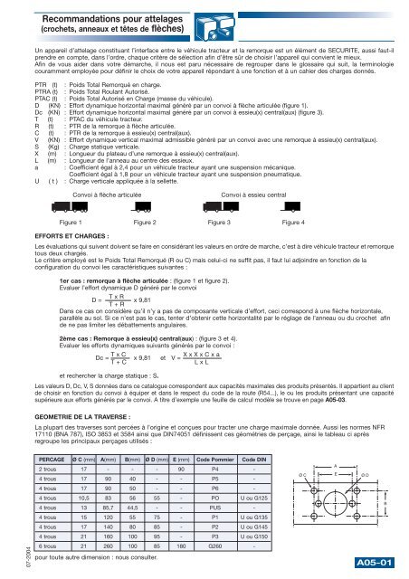
GEOMETRIE DE LA TRAVERSE :<br />
La plupart des traverses sont percées à l’origine et conçues <strong>pour</strong> tracter une charge maximale donnée. Aussi les normes NFR<br />
17110 (BNA 787), ISO 3853 et 3584 ainsi que DIN74051 définissent ces géométries de perçage, ainsi le tableau ci après<br />
regroupe les principaux perçages utilisés :<br />
PERCAGE Ø C (mm) A(mm) B(mm) Ø D (mm) E (mm) Code Pommier Code DIN<br />
2 trous 17 - - - 90 P4 -<br />
4 trous 17 90 40 - - P5 -<br />
4 trous 17 90 50 - - P6 -<br />
4 trous 10,5 83 56 55 - PO U ou G125<br />
4 trous 13 85,7 44,5 - - PUS -<br />
4 trous 15 120 55 75 - P1 U ou G135<br />
4 trous 17 140 80 85 - P2 U ou G145<br />
4 trous 21 160 100 95 - P3 U ou G150<br />
6 trous 21 260 100 85 180 G260 -<br />
<strong>pour</strong> toute autre dimension : nous consulter.<br />
Ø C<br />
A<br />
E<br />
Ø D<br />
B<br />
A05-01
<strong>Recommandations</strong> <strong>pour</strong> <strong>attelages</strong><br />
(crochets, anneaux et têtes de flèches)<br />
COMPATIBILITE :<br />
Dans certains cas Il se peut que le choix de l’anneau ou de l’attelage soit déja figé et qu’il faille déterminer l’élément complémentaire,<br />
il est alors nécessaire de prendre en compte la COMPATIBILITE des produits entre eux, le tableau suivant donne en zone<br />
ombrée la compatibilité des différents couples.<br />
APPAREILS D’ATTELAGE<br />
29.05001<br />
29.05006 à 007<br />
29.05009 à 014<br />
29.05015, 017, 026<br />
29.05019, 022 à 024, 027<br />
29.05100 à 107<br />
29.05300 à 302<br />
29.05400 à 402<br />
29.05020-021-025-030-050-051<br />
29.05110 à 116-119 à 121<br />
29.05200 à 203-205-206<br />
29.05305-306<br />
29.05405-406-410-411<br />
29.05500 à 502, 650 à 658<br />
29.05600 à 608-670<br />
29.05140 à 145<br />
29.05701 à 703<br />
29.05711 à 715<br />
29.05720, 721<br />
29.05722<br />
29.05723<br />
29.05750<br />
29.05730, 740, 741<br />
Dans tous les cas de figure, compte tenu des normes NFR 411.01 et 02 (BNA 263 et 264) et la spécification technique DEFA STAC<br />
1814 (militaire) et <strong>pour</strong> éviter tout danger :<br />
– <strong>pour</strong> une utilisation civile, le Bureau National de l’Automobile préconise un crochet bloqué en rotation autour de son axe<br />
longitudinal accouplé à son anneau (ou tête de flèche) pouvant tourner autour de son axe longitudinal,<br />
– en ce qui concerne l’application militaire, le crochet est tournant et l’anneau (42 x 76) fixe,<br />
– il en est de même <strong>pour</strong> les versions civiles des <strong>attelages</strong> à accoupler avec les anneaux DIN bagués de 40 et de 50mm d’après<br />
les normes DIN 74051, 74053, 74054 et ISO s’y rapportant.<br />
PARAMETRES DE MONTAGE :<br />
Sauf spécification contraire mentionnée dans la notice de montage, tous les appareils sont prévus <strong>pour</strong> être boulonnés. Les vis de<br />
fixation doivent être au minimum de classe 8.8, les écrous indesserrables ou équipés d’une rondelle grower sont d’une classe associée<br />
à la qualité de la vis. Les couples de serrage, fonction des diamètres sont préconisés dans le tableau ci-après :<br />
Classe des vis 8.8 10.9 12.9<br />
Diamètre (mm) 10 12 14 16 20 10 12 14 16 20 10 12 14 16 20<br />
Couple de serrage (m.daN) 5 8 13 20 40 6 11 18 30 55 8 13 22 30 65<br />
ENTRETIEN SECURITE :<br />
Ne le négligez pas !!<br />
Votre attelage est une pièce de sécurité. A ce titre, il doit être entretenu et surveillé régulièrement tous les 10 000 km ou tous les<br />
mois, premier échu.<br />
Lubrifier fréquemment, par l’intermédiaire des graisseurs ou par accès direct aux pièces mobiles, au moins tous les 10 000 km ou<br />
tous les mois.<br />
Vérifier en même temps que les usures et matages ne dépassent pas ce qui est préconisé dans la notice de montage livrée avec<br />
le produit ou à défaut de spécification 0,5 mm.<br />
PIECES DE RECHANGE :<br />
Consultez nous, nous vous conseillerons selon vos besoins.<br />
En cas de démontage, changer les goupilles et les accessoires “consommables“.<br />
ETUDES CONSEIL :<br />
Nous nous tenons à votre disposition <strong>pour</strong> répondre à tous vos besoins spécifiques et ponctuels de conseil, d’études et de fabrication.<br />
Nous nous réservons le soin d’apporter sur toutes les pièces constituants nos appareils, toute modification pouvant contribuer à<br />
une amélioration, ainsi toutes les dimensions reprises dans ce catalogue ne sont données qu’à titre informel et peuvent donner lieu<br />
à modification sans préavis de notre part.<br />
A05-02<br />
ANNEAUX<br />
20 x 40 30 x 50,6 36 x 56 42 x 68 42 x 76 29.44703 DIN 40 DIN 50<br />
29.44704 74054 74053<br />
07-2004
07-2004<br />
Exemples de calculs<br />
Utilisation d'une tête de flèche sur remorque à flèche articulée<br />
Recherche du D' (kN)<br />
Formule: D = T x R<br />
T + R<br />
x 9,81<br />
Il s'agit de trouver une tête de flèche sur le catalogue général ayant une valeur D supérieure ou égale à la valeur D'<br />
du convoi.<br />
Exemple numérique:<br />
D’ = 37 x 38<br />
37 + 38<br />
x 9,81<br />
P.T.R.A. 75<br />
D' = 183,9 kN<br />
P.T.R. remorque : R 38<br />
P.T.A.C. porteur : T 37<br />
Nous obtenons une valeur D' = 183,9 kN <strong>pour</strong> ce convoi. A partir de cette valeur D', rechercher la valeur D supérieure<br />
figurant au catalogue.<br />
Exemple: les têtes de flèches référencées ci-dessous peuvent répondre à ce cas d'utilisation.<br />
Réf. 29.05922 et 29.05917<br />
NOTA: sur une remorque à flèche articulée, les valeurs V (kN) et S (kg) sont négligeables. Elles ne seront pas prises<br />
en compte <strong>pour</strong> le calcul, dans la mesure où la flèche est horizontale parallèle au sol.<br />
Utilisation d'une tête de flèche sur remorque à essieu(x) central(aux)<br />
Recherche de V' (kN) et du Dc (kN)<br />
Formule: V =<br />
C x X x X x a<br />
L x L<br />
Dc = T x C<br />
T + C<br />
x 9,81<br />
Il s'agit de trouver une tête de flèche sur le catalogue général ayant à la fois une valeur de D et une valeur V<br />
supérieure ou égale à la valeur V' et DC’ du convoi.<br />
Exemple numérique : X = 6500 ; L = 5030 ; a = 1,80 (suspension pneumatique)<br />
P.T.R.A. 44<br />
P.T.R. remorque : C 19<br />
P.T.A.C. porteur : T 25<br />
19 x 6500 x 6500 x 1,80 25 x 19<br />
V’ = Dc’ = x 9,81<br />
5030 x 5030 25 + 19<br />
V' = 57,11 kN<br />
Pour le convoi cité ci-dessus, la valeur D'c est de 105,90 kN.<br />
Nous obtenons une valeur V' = 57,11 kN et D'c = 105,90 kN <strong>pour</strong> ce convoi. A partir de ces deux valeurs, rechercher<br />
les valeurs V et Dc supérieures figurant au catalogue.<br />
Exemple: les têtes de flèches référencées ci-dessous peuvent répondre à ce cas d'utilisation.<br />
Ref. 29.05922 et 29.05917<br />
Recommandation: <strong>pour</strong> contrôler la valeur de S (kg) (charge statique maximale admissible), nous conseillons de la<br />
mesurer en bout de flèche de remorque une fois celle-ci en ordre de marche (chargement uniformément réparti à<br />
l'intérieur de la remorque).<br />
L<br />
X<br />
A05-03
A trailer coupling, as the interface between a tractor and trailer, is an essential SAFETY item. Each selection criterion must be reviewed in<br />
sequence to be sure of selecting the best equipment for the trailer. In order to provide guidance for selecting the right coupling, we have<br />
compiled the following glossary of the terms commonly used to determine a coupling for a given function and to meet given specifications.<br />
TTW (t): Total Trailer Load<br />
TTWA (t): Authorised Total Trailer Load<br />
GVWR (t): Gross vehicle weight rating<br />
D (kN): Maximum Horizontal Dynamic Force produced by an articulated drawbar trailer (Figure 1)<br />
Dc (kN): Maximum Horizontal Dynamic Force produced by a central axle(s) trailer (Figure 3)<br />
T (t): TTW of the tractor<br />
R (t): TTW of the articulated drawbar trailer<br />
C (t): TTW of the central axle trailer<br />
V (kN): Maximum Acceptable Vertical Dynamic Force produced by a central axle trailer<br />
S (kg): Vertical static load<br />
X (m): Length of the loading platform of a central axle trailer<br />
L (m): Length of the drawbar at the centre of the axle<br />
a: Coefficient of 2.4 for a tractor with mechanical suspension<br />
Coefficient of 1.8 for a tractor with pneumatic suspension<br />
U (t): Vertical load applied to the fifth wheel<br />
Articulated drawbar trailer Central axle trailer<br />
Figure 1 Figure 2 Figure 3 Figure 4<br />
FORCES AND LOADS<br />
The following evaluations should be made assuming values encountered during services, i. e. with the tractor and trailer loaded.<br />
The criteria used is the Total Trailer Load (R or C), however, this is not sufficient. The characteristics values indicators must also be<br />
incorporated to reflect the configuration of the truck:<br />
Case 1: trailer with articulated drawbar: (Figures 1 and 2).<br />
Evaluate dynamic loads generated by the truck<br />
T x R<br />
D = x 9,81<br />
T+R<br />
In this case, it is assumed that there is no vertical load component; this corresponds to a horizontal drawbar which is parallel to the<br />
ground. If this is not the case, attempt to achieve horizontality by adjustment of the coupling or the drawbar without restricting<br />
angular displacement.<br />
Case 2: trailer with central axle(s): (Figures 3 and 4).<br />
Evaluate the following dynamic loads generated by the truck:<br />
T x C X x X x C x a<br />
Dc = x 9,81 and V =<br />
T + C L x L<br />
Find the static load, S.<br />
The D, Dc, V and S values given in this catalogue are the maximum capabilities of the products presented. In the respect of the<br />
highway code in force, the buyer is responsible for selecting a product (or products) with capabilities greater than the forces<br />
generated in a given truck. A typical calculation is presented for illustration purposes on page A05-06.<br />
UNDER BAR GEOMETRY<br />
Most under bar geometry are pre-drilled and designed to tract a predetermined maximum load. Standards NFR 17110 (BNA 787), ISO<br />
3853 and DIN 74051 establish hole geometries. The table below gives the principal mounting dimensions and holes we use :<br />
HOLE Ø C (mm) A(mm) B(mm) Ø D (mm) E (mm) Code Pommier Code DIN<br />
2 holes 17 - - - 90 P4 -<br />
4 holes 17 90 40 - - P5 -<br />
4 holes 17 90 50 - - P6 -<br />
4 holes 10,5 83 56 55 - PO U ou G125<br />
4 holes 13 85,7 44,5 - - PUS -<br />
4 holes 15 120 55 75 - P1 U ou G135<br />
4 holes 17 140 80 85 - P2 U ou G145<br />
4 holes 21 160 100 95 - P3 U ou G150<br />
6 holes 21 260 100 85 180 G260 -<br />
For other dimensions, consult us.<br />
A05-04<br />
Recommendations for couplings<br />
(couplings, drawbar eyes and drawbars heads)<br />
Ø C<br />
A<br />
E<br />
Ø D<br />
B<br />
07-2004
07-2004<br />
COMPATIBILITY<br />
In some cases, the coupling or drawbar eyes selection may already be made and additional hardware must be provided. In such<br />
cases, COMPATIBILITY of products is important. The shaded areas of the following table indicate compatible combinations.<br />
COUPLING DEVICES<br />
29.05001<br />
29.05006 to 007<br />
29.05009 to 014<br />
29.05015, 017, 026<br />
29.05019, 022 to 024, 027<br />
29.05100 to 107<br />
29.05300 to 302<br />
29.05400 to 402<br />
29.05020-021-025-030-050-051<br />
29.05110 to 116-119 to 121<br />
29.05200 to 203-205-206<br />
29.05305-306<br />
29.05405-406-410-411<br />
29.05500 to 502, 650 to 658<br />
29.05600 to 608-670<br />
29.05140 to 145<br />
29.05701 to 703<br />
29.05711 to 715<br />
29.05720, 721<br />
29.05722<br />
29.05723<br />
29.05750<br />
29.05730, 740, 741<br />
In all cases, given specifications NFR 411.01 and 02 (BNA 263 and 264) and the DEFA STAC (military) technical specification and<br />
to eliminate risks:<br />
- for non-military applications, the French "National Automotive Bureau" specifies that the coupling should be fixed to prevent<br />
rotation around its longitudinal axis and coupled to a ring (or drawbar) which is free to rotate around its longitudinal axis.<br />
- for military applications, the hook must be free to rotate and the drawbar (42 x 76) fixed.<br />
- the same applies to civil versions or drawbar to be coupled to DIN drawbar with 40 or 50 mm supports as per DIN standards<br />
74051, 74053, and 74054 and applicable ISO standards.<br />
ASSEMBLY PARAMETERS<br />
Excepted opposite otherwise mentioned in the technical notice, all drawbar devices are designed to be bolted. The bolt fastener<br />
must be minimum at least class 8.8, the locknuts or nuts with split lock washers should be of a class commensurate with the bolt<br />
used. Tightening torques as a function of diameter are tabulated below.<br />
Screw grade 8.8 10.9 12.9<br />
Diameter (mm) 10 12 14 16 20 10 12 14 16 20 10 12 14 16 20<br />
Tightening torque (m.daN) 5 8 13 20 40 6 11 18 30 55 8 13 22 30 65<br />
SAFETY MAINTENANCE<br />
Do not neglect safety maintenance.<br />
Your drawbar is an important safety item. As such, it should be maintained and inspected regularly every 10,000 km, or every<br />
month, whichever comes first.<br />
Lubricate drawbar frequently, either using lubricators or by directly accessing mobile components. Lubricate every 10,000 km, or<br />
every month.<br />
When lubricating, check that wear or peening depth does not exceed 0,5 mm.<br />
SPARE PARTS<br />
Consult us. We will advise you based on your needs.<br />
If the equipment is disassembled, reassemble using new pins and consumables.<br />
Recommendations for couplings<br />
(couplings, drawbar eyes and drawbars heads)<br />
20 x 40 30 x 50,6 36 x 56<br />
RINGS<br />
42 x 68 42 x 76 29.44703 DIN 40 DIN 50<br />
29.44704 74054 74053<br />
DESIGN SERVICES<br />
We are available to help with any of your specific requirements in the fields of consulting, design and manufacturing.<br />
We reserve the right to modify any component of our product to help improve them. All dimensions given in this catalogue are<br />
given for information only and may be modified at any time without prior notice.<br />
A05-05
Find D' (kN)<br />
Formula: D = T x R x 9,81<br />
T + R<br />
This calculation is performed to identify a drawbar in the catalogue with a D value greater than or equal to D'.<br />
T.T.W.A. 75<br />
Using a drawbar on a trailer with articulate drawbar<br />
T.T.W. Trailer : R 38<br />
T.T.W. Tractor : T 37<br />
Illustration<br />
D’ = 37 x 38<br />
x 9,81<br />
37 + 38<br />
D' = 183,9 kN<br />
This gives D' = 183.9 kN for this particular truck. Use the calculated D' value and find drawbar in our catalogue with<br />
a D value just above this value.<br />
Example: the drawbar references below are suitable for this case.<br />
Ref.: 29.05922 and 29.05917<br />
Note: On a trailer with an articulated drawbar, the V (kN) and S (kg) values are negligible. They can be ignored in the<br />
calculation if the boom is horizontal and parallel to the ground<br />
Using a drawbar on a trailer a central axle(s) trailer<br />
Find V' (kN)<br />
Formule: V =<br />
C x X x X x a<br />
L x L<br />
Dc’ =<br />
T x C<br />
T + C<br />
x 9,81<br />
This calculation is performed to identify a trailer in the catalogue with a V value greater than or equal to the V' value<br />
for the truck.<br />
Illustration: X = 6,500; L = 5,030; a = 1.80 (with pneumatic suspension).<br />
T.T.W.A. 44<br />
T.T.W. Trailer : C 19<br />
T.T.W. Tractor : T 25<br />
19 x 6500 x 6500 x 1,80 25 x 19<br />
V’ = Dc’ = x 9,81<br />
5030 x 5030 25 + 19<br />
V' = 57,11 kN<br />
For the above truck, the value of D'c is 105.90 kN.<br />
We obtain V' = 57.11 kN and D'c = 105.90 for this particular truck. Now find a model in the catalogue with V and Dc<br />
values greater the minimum calculated.<br />
Example: the drawbar head references below are suitable for this case.<br />
Ref.: 29.05922 and 29.05917<br />
Suggestion: to check the value of maximum admissible static loads, S (kg), we recommend you measure it at the<br />
end of the trailer drawbar once the trailer is in working condition (loads uniformly distributed on the trailer)<br />
A05-06<br />
Examples of calculations<br />
L<br />
X<br />
07-2004
07-2004<br />
Crochet 03.<br />
Coupling 03.<br />
Crochet 21 C.<br />
Coupling 21 C.<br />
Crochet 25 C.<br />
Coupling 25 C.<br />
Utilisation Utilisation<br />
Référence Type flèche articulée essieux centraux<br />
Part number Type Articulated Central axles<br />
drawbar utilisation utlisation<br />
29.05001<br />
29.05006<br />
29.05007<br />
29.05011<br />
29.05012<br />
29.05013<br />
29.05014<br />
29.05009<br />
Crochets fixes<br />
Kg<br />
Kg<br />
Kg<br />
1,200<br />
2,700<br />
3,600<br />
Conforme à la Directive Européenne 94/20/CEE<br />
In accordance to E.E.C. standard 94/20<br />
e2*94/20<br />
CEE<br />
*7511*<br />
e2*94/20<br />
CEE<br />
*7009*<br />
15<br />
10<br />
55<br />
95<br />
95<br />
155<br />
e2*94/20<br />
CEE<br />
*7008*<br />
Ø 23<br />
80 90<br />
50<br />
Ø 45<br />
74<br />
199<br />
160<br />
4 x Ø 13<br />
90 2 x Ø 17<br />
2 x Ø 17<br />
D (kN) Dc (kN) S (kg) (t) maxi (t) maxi**<br />
03 11 11 120 4,5 2<br />
21C/1<br />
21C/2<br />
25C/1<br />
25C/2<br />
17 17 120 7<br />
3,5<br />
25C/3<br />
25C/4<br />
25C/5<br />
20 20 120 8,5<br />
3,5<br />
95<br />
124<br />
Percé 2 trous Ø 17.<br />
2 holes Ø 17.<br />
90 4 x Ø 17<br />
** P.T.R. de la remorque donné à titre indicatif, à vérifier en fonction des caractéristiques du convoi, voir page A05-03.<br />
The max. permissible mass of the trailer is given for information. This value must be verified in accordance to the formula page A05-06.<br />
85,7<br />
44,5<br />
Percé 4 trous Ø 13.<br />
4 holes Ø 13.<br />
95<br />
Fixed couplings<br />
124<br />
90 2 x Ø 17<br />
Percé 2 trous Ø 17.<br />
2 holes Ø 17.<br />
40<br />
Percé 4 trous Ø 17.<br />
4 holes Ø 17.<br />
52<br />
126<br />
90<br />
29.05001 . 03<br />
Percé 2 trous Ø 17.<br />
2 holes Ø 17.<br />
85,7<br />
4 x Ø 13<br />
44,5<br />
29.05006 . 21C/1 29.05007 . 21C/2<br />
Percé 4 trous Ø 13.<br />
4 holes Ø 13.<br />
83<br />
4 x Ø 10,5<br />
29.05011 . 25C/1 29.05012 . 25C/2<br />
56<br />
Percé 4 trous Ø 10,5.<br />
4 holes Ø 10,5.<br />
90 4 x Ø 17<br />
29.05013 . 25C/3 29.05014 . 25C/4 29.05009 . 25C/5<br />
50<br />
Percé 4 trous Ø 17.<br />
4 holes Ø 17.<br />
A10-01
Crochet 35 C<br />
Coupling 35 C<br />
15<br />
95<br />
155<br />
Ø 45<br />
74<br />
199<br />
160<br />
29.05017<br />
Percé 4 trous Ø 13.<br />
4 holes Ø 13.<br />
29.05026<br />
Percé 4 trous Ø 17.<br />
4 holes Ø 17.<br />
** P.T.R. de la remorque donné à titre indicatif, à vérifier en fonction des caractéristiques du convoi, voir page A05-03.<br />
The max. permissible mass of the trailer is given for information. This value must be verified in accordance to the formula page A05-06.<br />
4 x Ø 13<br />
Utilisation Utilisation<br />
Référence flèche articulée essieux centraux<br />
Part number Articulated Central axles<br />
drawbar utilisation utilisation<br />
29.05017<br />
29.05026<br />
A10-02<br />
Crochet fixe<br />
Kg<br />
3,600<br />
Fixed coupling<br />
85,7<br />
44,5<br />
4 x Ø 17<br />
D (kN) (t) maxi (t) maxi** Dc (kN) S (kg) V (kN) (t) maxi (t) maxi**<br />
27 11 5 20 200 18 11 5<br />
27 11 5 27 200 25 11 5<br />
90<br />
40<br />
07-2004
07-2004<br />
Crochets fixes à boule<br />
e2*94/20<br />
CEE<br />
*0062*<br />
Crochet à boule.<br />
Ball coupling.<br />
124<br />
90 2 x Ø 17<br />
29.05019. 70C/1<br />
Percé 2 trous Ø 17.<br />
2 holes Ø 17.<br />
95<br />
Kg<br />
83<br />
29.05022. 70C/2<br />
Percé 4 trous Ø10,5.<br />
4 holes Ø 10,5.<br />
Conforme à la Directive Européenne 94/20/CEE<br />
In accordance to E.E.C. standard 94/20<br />
4 x Ø 10,5<br />
56<br />
85,7<br />
29.05023. 70C/3<br />
Percé 4 trous Ø 13.<br />
4 holes Ø 13.<br />
13<br />
78<br />
124<br />
160<br />
90 4 x Ø 17<br />
29.05024. 70C/4<br />
Percé 4 trous Ø 17.<br />
4 holes Ø 17.<br />
Ø 45<br />
Ø 50 205<br />
165<br />
77<br />
29.05027. 70C/5<br />
Percé 4 trous Ø 17.<br />
4 holes Ø 17.<br />
** P.T.R. de la remorque donné à titre indicatif, à vérifier en fonction des caractéristiques du convoi, voir page A05-03.<br />
The max. permissible mass of the trailer is given for information. This value must be verified in accordance to the formula page A05-06.<br />
4 x Ø 13<br />
Utilisation Utilisation<br />
Référence flèche articulée essieux centraux<br />
Part number Articulated Central axles<br />
drawbar utilisation utilisation<br />
29.05019, 022, 023, 024, 027<br />
4,200<br />
Modèle breveté<br />
Patented<br />
44,5<br />
Ball fixed couplings<br />
40<br />
90 4 x Ø 17<br />
D (kN) Dc (kN) S (kg) (t) maxi (t) maxi**<br />
31 31 375 35,5 3,5<br />
50<br />
A10-03
Crochet 39.<br />
Coupling 39.<br />
Crochet 45.<br />
Coupling 45.<br />
60<br />
109<br />
167<br />
Utilisation Utilisation<br />
Référence flèche articulée essieux centraux<br />
Part number Articulated Central axles<br />
drawbar utilisation utilisation<br />
29.05101<br />
29.05103<br />
29.05050<br />
29.05051<br />
fixe / fixed<br />
tournant / swivelling<br />
94<br />
127<br />
185<br />
Ø 45<br />
74<br />
197<br />
161<br />
195<br />
155<br />
D (kN) (t) maxi (t) maxi** Dc (kN) S (kg) V (kN) (t) maxi (t) maxi**<br />
Ø 45<br />
68<br />
29.05100 *<br />
Fixe à percer.<br />
Fixed to be drilled.<br />
29.05102*<br />
Tournant à percer.<br />
Rotating to be drilled.<br />
29.05050<br />
Fixe, percé 4 trous Ø 15.<br />
Fixed, 4 holes Ø 15.<br />
29.05051<br />
Tournant, percé 4 trous Ø 15.<br />
Rotating, 4 holes Ø 15.<br />
* Pour ces produits, se reporter aux conditions générales page A05-01 à A05-02. * For these products, see general specifications page A05-04 to A05-05<br />
** P.T.R. de la remorque donné à titre indicatif, à vérifier en fonction des caractéristiques du convoi, voir page A05-03.<br />
The max. permissible mass of the trailer is given for information. This value must be verified in accordance to the formula page A05-06.<br />
A10-04<br />
Crochets fixes<br />
ou tournants<br />
Kg<br />
Kg<br />
4,420<br />
9<br />
fixe / fixed<br />
tournant / swivelling<br />
Fixed or swivelling<br />
couplings<br />
155<br />
170<br />
80<br />
83 4 x Ø 10,5<br />
120 4 x Ø 15<br />
55<br />
56<br />
29.05101<br />
Fixe, percé 4 trous Ø 10,5<br />
Fixed, 4 holes Ø 10,5.<br />
29.05103<br />
Tournant, percé 4 trous Ø 10,5.<br />
Rotating, 4 holes Ø 10,5.<br />
25 10,5 5 14 250 6 8,5 2,5<br />
70 28,5 16 50 650 18 40 6,5<br />
90<br />
07-2004
07-2004<br />
Crochet 57 B.<br />
Coupling 57 B.<br />
Crochet 57 BC.<br />
Coupling 57 BC.<br />
Crochet 57 BD.<br />
Coupling 57 BD.<br />
Utilisation Utilisation<br />
Référence flèche articulée essieux centraux<br />
Part number Articulated Central axles<br />
drawbar utilisation utilisation<br />
29.05021<br />
29.05025<br />
29.05030<br />
Crochets fixes<br />
Kg<br />
Kg<br />
Kg<br />
6,500<br />
9,240<br />
9,770<br />
D (kN) (t) maxi (t) maxi** Dc (kN) S (kg) V (kN) (t) maxi (t) maxi**<br />
70 28,5 14 50 650 18 40 6,5<br />
195<br />
190<br />
29.05020 *<br />
A percer.<br />
To be drilled.<br />
Fixed couplings<br />
100<br />
200<br />
140<br />
120 4 x Ø 15<br />
29.05021<br />
Percé 4 trous Ø 15.<br />
4 holes Ø 15.<br />
29.05025<br />
Percé 4 trous Ø 17.<br />
4 holes Ø 17.<br />
29.05030<br />
Percé 4 trous Ø 21.<br />
4 holes Ø 21.<br />
100 44 20 70 900 25 44 9<br />
130 44 25 90 1000 35 44 13<br />
* Pour ces produits, se reporter aux conditions générales page A05-01 à A04-02. * For these products, see general specifications page A05-04 to A05-05.<br />
** P.T.R. de la remorque donné à titre indicatif, à vérifier en fonction des caractéristiques du convoi, voir page A05-03.<br />
The max. permissible mass of the trailer is given for information. This value must be verified in accordance to the formula page A05-06.<br />
200<br />
160<br />
55<br />
4 x Ø 17<br />
80 120<br />
4x Ø 21<br />
100 145<br />
A10-05
Crochet 41 A.<br />
Coupling 41 A.<br />
Crochet 57 C.<br />
Coupling 57 C.<br />
Crochet 64 A.<br />
Coupling 64 A.<br />
Utilisation Utilisation<br />
Référence flèche articulée essieux centraux<br />
Part number Articulated Central axles<br />
drawbar utilisation utilisation<br />
29.05106 - 29.05107<br />
29.05111 - 29.05113<br />
29.05116 - 29.05119<br />
D (kN) (t) maxi (t) maxi** Dc (kN) S (kg) V (kN) (t) maxi (t) maxi**<br />
50 20 8 27 650 14 11 5<br />
180<br />
190<br />
95<br />
29.05105*<br />
Fixe à percer.<br />
Fixed to be drilled.<br />
29.05104 *<br />
Tournant à percer.<br />
Rotating to be drilled.<br />
29.05110 *<br />
Fixe, à percer.<br />
Fixed, to be drilled.<br />
29.05112 *<br />
Tournant, à percer.<br />
Rotating, to be drilled.<br />
29.05115 *<br />
Fixe à percer.<br />
Fixed to be drill.<br />
29.05114 *<br />
Tournant, à percer.<br />
Rotating, to be drilled.<br />
120<br />
120 4 x Ø 15<br />
55<br />
29.05106<br />
Fixe, percé 4 trous Ø 15.<br />
Fixed, 4 holes Ø 15.<br />
29.05107<br />
Tournant, percé 4 trous Ø 15.<br />
Rotating, 4 holes Ø 15.<br />
140 4 x Ø 17<br />
80<br />
29.05116<br />
Fixe, percé 4 trous Ø 17.<br />
Fixed, 4 holes Ø 17.<br />
29.05119<br />
Tournant, percé 4 trous Ø 17.<br />
Rotating, 4 holes Ø 17.<br />
*Pour ces produits, se reporter aux conditions générales page A05-01 à A05-02. *For these products, see general specifications page A05-04 to A05-05.<br />
**P.T.R. de la remorque donné à titre indicatif, à vérifier en fonction des caractéristiques du convoi, voir page A05-03.<br />
The max. permissible mass of the trailer is given for information. This value must be verified in accordance to the formula page A05-06.<br />
A10-06<br />
Crochets fixes<br />
ou tournants<br />
Kg<br />
Kg<br />
Kg<br />
5,850<br />
11<br />
13<br />
Fixed or rotating<br />
couplings<br />
190<br />
120<br />
140 4 x Ø 17<br />
80<br />
29.05111<br />
Fixe, percé 4 trous Ø 17.<br />
Fixed, 4 holes Ø 17.<br />
29.05113<br />
Tournant, percé 4 trous Ø 17.<br />
Rotating, 4 holes Ø 17.<br />
80 36 16 40 650 18 17 7<br />
90 36 20 70 900 25 44 9,5<br />
07-2004
07-2004<br />
Crochets fixes ou tournants<br />
à double semelle<br />
Crochet 64 CP1.<br />
Coupling 64 CP1.<br />
Crochet 64 CP2.<br />
Coupling 64 CP2.<br />
Crochet 64 DP3.<br />
Coupling 64 DP3.<br />
Kg<br />
Kg<br />
Utilisation Utilisation<br />
Référence flèche articulée essieux centraux<br />
Part number Articulated Central axles<br />
drawbar utilisation utilisation<br />
29.05200 - 29.05202<br />
29.05201 - 29.05203<br />
29.05205 - 29.05206<br />
15,500<br />
19<br />
Fixed or swivelling coupling<br />
with double sole<br />
29.05200<br />
64 CP1 fixe, percé 4 trous Ø 15.<br />
64 CP1 fixed, 4 holes Ø 15.<br />
29.05202<br />
64 CP1 tournant, percé 4 trous Ø 15.<br />
64 CP1 rotating, 4 holes Ø 15.<br />
29.05201<br />
64 CP2 fixe, percé 4 trous Ø 17.<br />
64 CP2 fixed, 4 holes Ø 17.<br />
29.05203<br />
64 CP2 tournant, percé 4 trous Ø 17.<br />
64 CP2 rotating, 4 holes Ø 17.<br />
D (kN) (t) maxi (t) maxi** Dc (kN) S (kg) V (kN) (t) maxi (t) maxi**<br />
70 28,5 16 50 650 18 40 6,5<br />
100 40 20 70 900 25 44 9<br />
190<br />
140<br />
120 4 x Ø 15<br />
200<br />
160<br />
55<br />
4 x Ø 17<br />
80 120<br />
4 x Ø 21<br />
100 140<br />
29.05205<br />
64 DP3 fixe, percé 4 trous Ø 21.<br />
64 DP3 fixed, 4 holes Ø 21.<br />
29.05206<br />
64 DP3 tournant, percé 4 trous Ø 21.<br />
64 DP3 rotating, 4 holes Ø 21.<br />
120 50 30 100 1000 45 44 17<br />
** P.T.R. de la remorque donné à titre indicatif, à vérifier en fonction des caractéristiques du convoi, voir page A05-03.<br />
The max. permissible mass of the trailer is given for information. This value must be verified in accordance to the formula page A05-06.<br />
A10-07
Crochets élastiques en<br />
applique non tournants<br />
Crochet 32 B.<br />
Coupling 32 B.<br />
Crochet 51 B.<br />
Coupling 51 B.<br />
29.05305 *<br />
A percer.<br />
To be drilled.<br />
Utilisation Utilisation<br />
Référence flèche articulée essieux centraux<br />
Part number Articulated Central axles<br />
drawbar utilisation utilisation<br />
29.05302<br />
29.05306<br />
14<br />
230<br />
280<br />
Ø 45<br />
190<br />
150<br />
29.05300 *<br />
A percer.<br />
To be drilled.<br />
29.05302<br />
Percé 4 trous Ø 15.<br />
4 holes Ø 15.<br />
29.05306<br />
Percé 4 trous Ø 17.<br />
4 holes Ø 17.<br />
D (kN) (t) maxi (t) maxi** Dc (kN) S (kg) V (kN) (t) maxi (t) maxi**<br />
25 10 5 23 200 6 9,5 2,5<br />
200<br />
62<br />
120<br />
180<br />
92<br />
120 4 x Ø 15<br />
80 32 16 38 650 16 18,5 5,5<br />
* Pour ces produits, se reporter aux conditions générales page A05-01 à A05-02. * For these products, see general specifications page A05-04 to A05-05.<br />
** P.T.R. de la remorque donné à titre indicatif, à vérifier en fonction des caractéristiques du convoi, voir page A05-03.<br />
The max. permissible mass of the trailer is given for information. This value must be verified in accordance to the formula page A05-06.<br />
A10-08<br />
Kg<br />
Kg<br />
7,400<br />
18,200<br />
No rotating flexible<br />
couplings<br />
140<br />
55<br />
4 x Ø 17<br />
80<br />
07-2004
07-2004<br />
Utilisation Utilisation<br />
Référence flèche articulée essieux centraux<br />
Part number Articulated Central axles<br />
drawbar utilisation utilisation<br />
29.05401<br />
29.05406<br />
29.05410<br />
Crochets élastiques<br />
non tournants<br />
Crochet 36 B.<br />
Coupling 36 B.<br />
Crochet 55 B.<br />
Coupling 55 B.<br />
Crochet 56 A.<br />
Coupling 56 A.<br />
Kg<br />
Kg<br />
Kg<br />
6,900<br />
16,400<br />
19<br />
e2*94/20<br />
CEE<br />
*0053*<br />
Ø 77<br />
12<br />
120 109<br />
No rotating flexible<br />
couplings<br />
197<br />
160<br />
29.05401<br />
Percé 4 trous Ø 10,5.<br />
4 holes Ø 10,5.<br />
29.05405 *<br />
A percer.<br />
To be drilled.<br />
D (kN) (t) maxi (t) maxi** Dc (kN) S (kg) V (kN) (t) maxi (t) maxi**<br />
31 35,5 3,5 31 375 - 35,5 3,5<br />
165<br />
Ø 45<br />
76<br />
200<br />
83 4 x Ø 10,5<br />
Conforme à la Directive Européenne 94/20/CEE<br />
In accordance with E.E.C. standard 94/20<br />
56<br />
110<br />
140 4 x Ø 17<br />
29.05406<br />
Percé 4 trous Ø 17.<br />
4 holes Ø 17.<br />
29.05410<br />
Percé 4 trous Ø 21.<br />
4 holes Ø 21.<br />
80 32 16 38 650 16 18,5 5,5<br />
120 50 25 106 1000 50 44 19<br />
* Pour ces produits, se reporter aux conditions générales page A05-01 à A05-02. * For these products, see general specifications page A05-04 to A05-05.<br />
** P.T.R. de la remorque donné à titre indicatif, à vérifier en fonction des caractéristiques du convoi, voir page A05-03.<br />
The max. permissible mass of the trailer is given for information. This value must be verified in accordance to the formula page A05-06.<br />
200<br />
29.05411*<br />
A percer.<br />
To be drilled.<br />
160<br />
80<br />
140<br />
4 x Ø 21<br />
100<br />
A10-09
Crochets amortis fixes Fixed shock absorber<br />
couplings<br />
Crochet 64 EP1.<br />
Coupling 64 EP1.<br />
Crochet 64 EP2.<br />
Coupling 64 EP2.<br />
Crochet 64 EP3.<br />
Coupling 64 EP3.<br />
29.05501<br />
Fixe 64 EP2, percé 4 trous Ø 17.<br />
Fixed 64 EP2, 4 holes Ø 17.<br />
Utilisation Utilisation<br />
Référence flèche articulée essieux centraux<br />
Part number Articulated Central axles<br />
drawbar utilisation utilisation<br />
29.05500<br />
29.05501<br />
29.05502<br />
Ø 108<br />
Ø 137<br />
182<br />
140<br />
132<br />
145<br />
80 122<br />
20 maxi<br />
172<br />
25 maxi<br />
29.05502<br />
Fixe 64 EP3, percé 4 trous Ø 21.<br />
Fixed 64 EP3, 4 holes Ø 21.<br />
D (kN) (t) maxi (t) maxi** Dc (kN) S (kg) V (kN) (t) maxi (t) maxi**<br />
70 28,5 16 50 650 18 44 6,5<br />
17<br />
23<br />
235<br />
170<br />
240<br />
Ø 45<br />
238<br />
195<br />
85<br />
Ø 45<br />
85<br />
150<br />
120<br />
238<br />
195<br />
205<br />
160<br />
4 x Ø 15<br />
55 87<br />
29.05500<br />
Fixe, percé 4 trous Ø 15.<br />
Fixed, 4 holes Ø 15.<br />
100 40 20 70 900 25 44 9<br />
120 44 30 90 1000 35 44 13<br />
** P.T.R. de la remorque donné à titre indicatif, à vérifier en fonction des caractéristiques du convoi, voir page A05-03.<br />
The max. permissible mass of the trailer is given for information. This value must be verified in accordance to the formula page A05-06.<br />
A10-10<br />
Kg<br />
Kg<br />
Kg<br />
14,500<br />
18,500<br />
19<br />
4 x Ø 21<br />
100 142<br />
07-2004
07-2004<br />
Crochet fixe ou tournant<br />
automatique<br />
Utilisation Utilisation<br />
Référence flèche articulée essieux centraux<br />
Reference Articulated Central axles<br />
drawbar utilisation utlisation<br />
29.05120<br />
29.05121<br />
Kg 25<br />
Crochet 77<br />
Coupling 77<br />
Ce modèle existe en version amortie, nous consulter<br />
Exist in shock absorber version, please consult us<br />
Fixed : Swivelling<br />
automatic coupling<br />
D (kN) (t) maxi (t) maxi** Dc (kN) S (kg) V (kN) (t) maxi (t) maxi**<br />
206<br />
160<br />
4 x Ø 21<br />
100 140<br />
29.05120<br />
Fixe, percé 4 trous Ø 21.<br />
Fixed, 4 holes Ø 21.<br />
29.05121<br />
Tournant, percé 4 trous Ø 21.<br />
Rotating, 4 holes Ø 21.<br />
120 44 22 85 1000 30 44 12<br />
** P.T.R. de la remorque donné à titre indicatif, à vérifier en fonction des caractéristiques du convoi, voir page A05-03.<br />
The max. permissible mass of the trailer is given for information. This value must be verified in accordance to the formula page A05-06.<br />
A10-11
INTEGRAL asservi avec<br />
rattrapage de jeu<br />
L’attelage INTEGRAL à broche automatique est conçu <strong>pour</strong> être accouplé avec des anneaux tournants BNA (42 x 68) ou DEFA (42 x 76).<br />
The INTEGRAL automatic coupling is designed to be coupled rotating-drawbar eyes to BNA (Ø 42 x Ø 68) or DEFA (Ø 42 x Ø 76).<br />
e2*94/20<br />
356<br />
CEE<br />
*5001*<br />
e2*94/20<br />
CEE<br />
*5003*<br />
e2*94/20<br />
CEE<br />
*5002*<br />
INTEGRAL asservi, Kg 43<br />
visserie classe 12,9 fournie.<br />
Actuator operated INTEGRAL,<br />
delivered with class 12.9 bolts.<br />
2. Fermé<br />
Closed<br />
133<br />
Ø 50<br />
125<br />
33<br />
112 387<br />
Compatibilité longueur anneau BNA–DEFA.<br />
Longueur mini entre l’axe de l’oeil et la base de la collerette.<br />
Length compatibility between BNA-DEFA drawbar eyes.<br />
Minimal length between ring axle and flange.<br />
Ø 84<br />
Utilisation Utilisation<br />
Référence flèche articulée essieux centraux<br />
Part number Articulated Central axles<br />
drawbar utilisation utlisation<br />
29.05653<br />
29.05654<br />
29.05655<br />
A15-01<br />
1. Ouvert<br />
Openend<br />
Conforme à la Directive Européenne 94/20/CEE<br />
In accordance to E.E.C. standard 94/20<br />
Ø 68 mini<br />
124 mini<br />
Actuator operated INTEGRAL<br />
with shock absorber<br />
Boitier de commande pneumatique.<br />
Air remote control.<br />
*Index de contrôle<br />
*Control index<br />
Position sortie : déverrouillé<br />
Visible index : unlocked<br />
Position rentrée : verrouillé<br />
Unvisible index : locked<br />
D (kN) (t) maxi (t) maxi** Dc (kN) S (kg) V (kN) (t) maxi (t) maxi**<br />
180 75 37 125 1000 90 44 26<br />
100 40 21 70 900 25 29 13<br />
180 75 37 120 1000 50 44 19<br />
** P.T.R. de la remorque donné à titre indicatif, à vérifier en fonction des caractéristiques du convoi, voir page A05-03.<br />
The max. permissible mass of the trailer is given for information. This value must be verified in accordance to the formula page A05-06.<br />
1<br />
2<br />
180<br />
260<br />
140<br />
160<br />
300<br />
Broche<br />
Pin<br />
2 x M20<br />
100<br />
4 x Ø 21<br />
29.05653<br />
INTÉGRAL G260 asservi. A utiliser sur<br />
des traverses ép. 24 mm mini.<br />
Actuator operated INTEGRAL G260.<br />
To be used on tow bar mini 24 mm th.<br />
80<br />
4 x M 16<br />
29.05654<br />
INTÉGRAL G145 asservi. A utiliser<br />
sur des traverses ép. 10 mm mini.<br />
Actuator operated INTEGRAL G 145.<br />
To be used on tow bar mini 10 mm th.<br />
100 150<br />
4 x M 20<br />
29.05655<br />
INTÉGRAL G150 asservi. A utiliser<br />
sur des traverses ép. 24 mm mini.<br />
Actuator operated INTEGRAL G 150.<br />
To be used on tow bar mini 24 mm th.<br />
07-2004
07-2004<br />
356<br />
INTEGRAL manuel avec<br />
rattrapage de jeu<br />
INTEGRAL manuel, Kg 40,500<br />
visserie classe 12,9 fournie.<br />
Manually INTEGRAL,<br />
delivered with class 12.9 bolts.<br />
2. Fermé<br />
Closed<br />
133<br />
Ø 50<br />
125<br />
33<br />
112 387<br />
Ø 84<br />
Utilisation Utilisation<br />
Référence flèche articulée essieux centraux<br />
Part number Articulated Central axles<br />
drawbar utilisation utlisation<br />
29.05650<br />
29.05651<br />
29.05652<br />
1. Ouvert<br />
Opened<br />
Ø 68 mini<br />
124 mini<br />
Compatibilité longueur anneau BNA–DEFA.<br />
Longueur mini entre l’axe de l’oeil et la base de la collerette.<br />
Length compatibility between BNA-DEFA drawbar eyes.<br />
Minimal length between ring axle and flange.<br />
Manually operated INTEGRAL<br />
with shock absorber<br />
L’attelage INTEGRAL à broche automatique est conçu <strong>pour</strong> être accouplé avec des anneaux tournants BNA (42 x 68) ou DEFA (42 x 76).<br />
The INTEGRAL automatic coupling is designed to be coupled rotating-drawbar eyes to BNA (Ø 42 x Ø 68) or DEFA (Ø 42 x Ø 76).<br />
e2*94/20<br />
CEE<br />
*5001*<br />
e2*94/20<br />
CEE<br />
*5003*<br />
e2*94/20<br />
CEE<br />
*5002*<br />
Conforme à la Directive Européenne 94/20/CEE<br />
In accordance to E.E.C. standard 94/20<br />
*Index de contrôle<br />
*Control index<br />
D (kN) (t) maxi (t) maxi** Dc (kN) S (kg) V (kN) (t) maxi (t) maxi**<br />
180 75 37 125 1000 90 44 26<br />
100 40 21 70 900 25 29 13<br />
180 75 37 120 1000 50 44 19<br />
** P.T.R. de la remorque donné à titre indicatif, à vérifier en fonction des caractéristiques du convoi, voir page A05-03.<br />
The max. permissible mass of the trailer is given for information. This value must be verified in accordance to the formula page A05-06.<br />
1<br />
2<br />
Position sortie : déverrouillé<br />
Visible index : unlocked<br />
Position rentrée : verrouillé<br />
Unvisible index : locked<br />
180<br />
260<br />
140<br />
160<br />
300<br />
Broche<br />
Pin<br />
2 x M20<br />
100<br />
4 x Ø 21<br />
29.05650<br />
INTÉGRAL G260 manuel. A utiliser<br />
sur des traverses ép. 24 mm mini.<br />
Manually INTEGRAL G260. To be<br />
used on tow bar mini 24 mm th.<br />
80<br />
4 x M 16<br />
29.05651<br />
INTÉGRAL G145 manuel. A utiliser<br />
sur des traverses ép. 10 mm mini.<br />
Manually INTEGRAL G 145. To be<br />
used on tow bar mini 10 mm th.<br />
100 150<br />
4 x M 20<br />
29.05652<br />
INTÉGRAL G150 manuel. A utiliser<br />
sur des traverses ép. 24 mm mini.<br />
Manually INTEGRAL G 150. To be<br />
used on tow bar mini 24 mm th.<br />
A15-02
INTEGRAL manuel sans<br />
rattrapage de jeu<br />
INTEGRAL manuel, Kg 35<br />
visserie classe 12,9 fournie.<br />
Manually INTEGRAL,<br />
delivered with class 12.9 bolt.<br />
2. Fermé<br />
Closed<br />
356<br />
133<br />
Ø 50<br />
112<br />
125<br />
33<br />
Utilisation Utilisation<br />
Référence flèche articulée essieux centraux<br />
Part number Articulated Central axles<br />
drawbar utilisation utlisation<br />
29.05656<br />
29.05657<br />
29.05658<br />
1. Ouvert<br />
Open<br />
Ø 68 mini<br />
124 mini<br />
Compatibilité longueur anneau BNA–DEFA.<br />
Longueur mini entre l’axe de l’oeil et la base de la collerette.<br />
Length compatibility between BNA-DEFA drawbar eyes..<br />
Minimal length between ring axle and flange.<br />
Actuator operated INTEGRAL<br />
without shock absorber<br />
L’attelage INTEGRAL à broche automatique est conçu <strong>pour</strong> être accouplé avec des anneaux tournants BNA (42 x 68) ou DEFA (42 x 76).<br />
The INTEGRAL automatic coupling is designed to be coupled rotating-drawbar eyes to BNA (Ø 42 x Ø 68) or DEFA (Ø 42 x Ø 76).<br />
e2*94/20<br />
CEE<br />
*5001*<br />
e2*94/20<br />
CEE<br />
*5003*<br />
e2*94/20<br />
CEE<br />
*5002*<br />
A15-03<br />
Conforme à la Directive Européenne 94/20/CEE<br />
In accordance to E.E.C. standard 94/20<br />
*Index de contrôle<br />
*Control index<br />
Position sortie : déverrouillé<br />
Visible index : unlocked<br />
Position rentrée : verrouillé<br />
Unvisible index : locked<br />
D (kN) (t) maxi (t) maxi** Dc (kN) S (kg) V (kN) (t) maxi (t) maxi**<br />
180 75 37 125 1000 90 44 26<br />
100 40 21 70 900 25 29 13<br />
180 75 37 120 1000 50 44 19<br />
1<br />
2<br />
180<br />
260<br />
140<br />
160<br />
300<br />
Broche<br />
Pin<br />
2 x M20<br />
100<br />
4 x Ø 21<br />
29.05656<br />
INTÉGRAL G260 manuel. A utiliser sur<br />
des traverses ép. 24 mm mini.<br />
Manually INTEGRAL G260. To be<br />
used on tow bar mini 24 mm th.<br />
80<br />
4 x M 16<br />
29.05657<br />
INTÉGRAL G145 manuel. A utiliser<br />
sur des traverses ép. 10 mm mini.<br />
Manually INTEGRAL G 145. To be<br />
used on tow bar mini 10 mm th.<br />
100 150<br />
4 x M 20<br />
29.05658<br />
INTÉGRAL G150 manuel. A utiliser<br />
sur des traverses ép. 24 mm mini.<br />
To be used on tow bar mini 24 mm th.<br />
Manually INTEGRAL G 150.<br />
** P.T.R. de la remorque donné à titre indicatif, à vérifier en fonction des caractéristiques du convoi, voir page A05-03.<br />
The max. permissible mass of the trailer is given for information. This value must be verified in accordance to the formula page A05-06.<br />
07-2004
07-2004<br />
L'attelage à broche automatique A500 est prévu <strong>pour</strong> être acouplé avec un anneau bagué à alésage de 40 mm et d'épaisseur 30,5 mm (conforme à la norme DIN 74054).<br />
The A500 automatic coupling is designed to be coupled to a ring with a 40 mm hole and 30,5 mm thickness (in accordance with norm DIN 74054).<br />
Fermé<br />
Locked<br />
2<br />
A 500 manuel tournant<br />
Ouvert<br />
Open<br />
1<br />
Conforme à la norme DIN 74051 et homologué T.Ü.V.<br />
In accordance with DIN 74051 and T.Ü.V. approved<br />
* Système de verrouillage assurant une double sécurité.<br />
* Locking system allowing a double security.<br />
Utilisation Utilisation<br />
Référence flèche articulée essieux centraux<br />
Part number Articulated Central axles<br />
drawbar utilisation utlisation<br />
155<br />
120<br />
180<br />
140<br />
D (kN) (t) maxi (t) maxi** Dc (kN) S (kg) V (kN) (t) maxi (t) maxi**<br />
29.05600 –A 500-G 135 70 28,5 14,5 54 700 18 40 6,5<br />
29.05601 –A 500-G 145 100 40 19 70 950 23 44 9<br />
29.05602 –A 500-G 150 120 44 25 72 950 24 44 9,5<br />
29.05608 –A 500-EC 13 120 44 30 91 1000 33 44 13<br />
4 x Ø 15<br />
55<br />
29.05600 G 135<br />
Percé 4 trous Ø 15.<br />
4 holes Ø 15.<br />
90<br />
4 x Ø 17<br />
80 120<br />
29.05601 G 145<br />
Percé 4 trous Ø 17.<br />
4 holes Ø 17.<br />
Rotating manual A 500<br />
200<br />
160<br />
Position sortie : déverrouillé<br />
Visible index : unlocked<br />
*Index de contrôle<br />
*Control index<br />
Position rentrée : verrouillé<br />
Unvisible index : locked<br />
4 x Ø 21<br />
100 140<br />
29.05602 G 150 – 29.05608 EC 13<br />
Percé 4 trous Ø 21.<br />
4 holes Ø 21.<br />
** P.T.R. de la remorque donné à titre indicatif, à vérifier en fonction des caractéristiques du convoi, voir page A05-03.<br />
The max. permissible mass of the trailer is given for information. This value must be verified in accordance to the formula page A05-06.<br />
1<br />
2<br />
Attelage A 500<br />
A 500 coupling<br />
G 135 : Kg 36<br />
G 145; G 150; EC 13 :<br />
Ø 40<br />
Kg<br />
Broche<br />
Pin<br />
41<br />
30,5<br />
Compatibilité avec anneau D40 (74054).<br />
Compatibility with D40 drawbar eyes (74054).<br />
A15-04
L’attelage à broche automatique Compact 40 est prévu <strong>pour</strong> être accouplé avec un anneau bagué à alésage de 40 mm et d’épaisseur 30,5 mm (conforme à la norme DIN 74054))<br />
The Compact 40 automatic coupling is designed to be coupled to a ring with a 40 mm hole and 30,5 thickness (in accordance with DIN 74054).<br />
Utilisation Utilisation<br />
Référence flèche articulée essieux centraux<br />
Part number Articulated Central axles<br />
drawbar utilisation utlisation<br />
29.05670<br />
Compact 40 manuel<br />
tournant<br />
e2*94/20<br />
CEE<br />
*1058*<br />
A15-05<br />
Conforme à la Directive Européenne 94/20/CEE<br />
In accordance to E.E.C. standard 94/20<br />
Ouvert<br />
Opened<br />
Compact 40<br />
Compact 40<br />
Amplitude de rotation limitée à +/– 30°<br />
Max. rotation angle : +/– 30°<br />
Fermé<br />
Closed<br />
Rotating manual<br />
Compact 40<br />
Position sortie : déverrouillé<br />
Visible index : unlocked<br />
*Index de contrôle<br />
*Control index<br />
Position rentrée : verrouillé<br />
Unvisible index : locked<br />
29.05670<br />
Percé 4 trous Ø 15.<br />
4 holes Ø 15.<br />
D (kN) (t) maxi (t) maxi** Dc (kN) S (kg) V (kN) (t) maxi (t) maxi**<br />
54 32,5 6,5 54 700 18 32,5 6,5<br />
** P.T.R. de la remorque donné à titre indicatif, à vérifier en fonction des caractéristiques du convoi, voir page A05-03.<br />
The max. permissible mass of the trailer is given for information. This value must be verified in accordance to the formula page A05-06.<br />
1<br />
2<br />
155<br />
120<br />
4 x Ø 15<br />
55<br />
Broche<br />
Pin<br />
Modèle équipé d’une palette avec des<br />
amortisseurs polyuréthane limitant les jeux verticaux<br />
With vertical shock absorber<br />
Kg<br />
17<br />
Ø 40<br />
30,5<br />
Compatibilité avec anneau D40 (74054).<br />
Compatibility with D40 drawbar eyes (74054).<br />
90<br />
07-2004
07-2004<br />
MINITRACT manuel fixe<br />
L’attelage à broche automatique MINITRACT est prévu <strong>pour</strong> être accouplé avec un anneau bagué à alésage de 40 mm et d’épaisseur 30,5 mm (conforme à la norme DIN 74054))<br />
The MINITRACT automatic coupling is designed to be coupled to a ring with a 40 mm hole and 30,5 thickness (in accordance with DIN 74054).<br />
e2*94/20<br />
CEE<br />
*1033*<br />
e2*94/20<br />
CEE<br />
*1034*<br />
MINITRACT manuel fixe<br />
Fixed manual MINITRACT<br />
57<br />
Ø 38,5<br />
85<br />
121<br />
140<br />
52<br />
151<br />
Ouvert<br />
Opened<br />
Fermé<br />
Closed<br />
Utilisation Utilisation<br />
Référence flèche articulée essieux centraux<br />
Part number Articulated Central axles<br />
drawbar utilisation utlisation<br />
29.05680<br />
29.05681<br />
Conforme à la Directive Européenne 94/20/CEE<br />
In accordance to E.E.C. standard 94/20<br />
Kg<br />
5,500<br />
Fixed manual MINITRACT<br />
Position sortie : déverrouillé<br />
Visible index : unlocked<br />
*Index de contrôle<br />
*Control index<br />
Position rentrée : verrouillé<br />
Unvisible index : locked<br />
** P.T.R. de la remorque donné à titre indicatif, à vérifier en fonction des caractéristiques du convoi, voir page A05-03.<br />
The max. permissible mass of the trailer is given for information. This value must be verified in accordance to the formula page A05-06.<br />
1<br />
2<br />
110<br />
83<br />
29.05680<br />
Percé 4 trous Ø 10,5.<br />
4 holes Ø 10,5.<br />
155<br />
120<br />
29.05681<br />
Percé 4 trous Ø 15.<br />
4 holes Ø 15.<br />
Broche<br />
Pin<br />
4 x Ø 10,5<br />
56 85<br />
4 x Ø 15<br />
D (kN) (t) maxi (t) maxi** Dc (kN) S (kg) V (kN) (t) maxi (t) maxi**<br />
31 35,5 3,5 31 375 - 35,5 3,5<br />
31 35,516,7 3,54,2 31 375 12 35,516,7 3,54,2<br />
Ø 40<br />
30,5<br />
Compatibilité avec anneau D40 (74054).<br />
Compatibility with D40 drawbar eyes (74054).<br />
55<br />
90<br />
A15-06
EUROTRACT asservi<br />
tournant<br />
e2*94/20<br />
CEE<br />
*9045*<br />
e2*94/20<br />
CEE<br />
*9046*<br />
L’attelage EUROTRACT tournant à broche automatique est conçu <strong>pour</strong> être accouplé avec un anneau D50 (74053).<br />
The rotating EUROTRACT automatic coupling has been designed for use with D50 drawbar eyes (74053).<br />
Kg<br />
56,500<br />
EUROTRACT asservi tournant<br />
visserie classe 12,9 fournie.<br />
Rotating servo EUROTRACT<br />
delivered with class 12.9 bolts.<br />
360<br />
220<br />
2. Fermé<br />
Closed<br />
246<br />
108<br />
Utilisation Utilisation<br />
Référence Catégorie flèche articulée essieux centraux<br />
Part number type Articulated Central axles<br />
drawbar utilisation utlisation<br />
29.05140<br />
29.05141<br />
29.05142<br />
A15-07<br />
e2*94/20<br />
CEE<br />
*9047*<br />
Conforme à la Directive Européenne 94/20/CEE<br />
In accordance to E.E.C. standard 94/20<br />
302<br />
1. Ouvert<br />
Opened<br />
Broche<br />
Pin<br />
Ø48,9 Ø 48,5<br />
Ø 93<br />
37<br />
178 220<br />
Rotating servo<br />
EUROTRACT<br />
Boîtier de commande<br />
pneumatique<br />
avec équerre<br />
Pneumatic remote<br />
control with square<br />
*Index de contrôle<br />
*Control index<br />
140 100<br />
Position sortie : déverrouillé<br />
Visible index : unlocked<br />
Position rentrée : verrouillé<br />
Unvisible index : locked<br />
D (kN) (t) maxi (t) maxi** Dc (kN) S (kg) V (kN) (t) maxi (t) maxi**<br />
C50-X 190 76 38 135 1000 72,5 52 26<br />
C50-6 190 76 38 120 1000 50 52 19<br />
C50-5 130 52 26 90 1000 35 44 13<br />
** P.T.R. de la remorque donné à titre indicatif, à vérifier en fonction des caractéristiques du convoi, voir page A05-03.<br />
The max. permissible mass of the trailer is given for information. This value must be verified in accordance to the formula page A05-06.<br />
1<br />
2<br />
Ø 50<br />
Broche<br />
Pin<br />
Compatibilité avec anneau D50 (74053)<br />
Compatibility with D50 (74053)<br />
drawbar eyes<br />
160<br />
200<br />
45<br />
07-2004
07-2004<br />
EUROTRACT manuel<br />
tournant<br />
e2*94/20<br />
CEE<br />
*9045*<br />
e2*94/20<br />
CEE<br />
*9046*<br />
e2*94/20<br />
CEE<br />
*9047*<br />
Kg<br />
53<br />
EUROTRACT manuel tournant<br />
visserie classe 12,9 fournie.<br />
Rotating manual EUROTRACT<br />
delivered with class 12.9 bolts.<br />
360<br />
220<br />
2. Fermé<br />
Closed<br />
246<br />
108<br />
Utilisation Utilisation<br />
Référence Catégorie flèche articulée essieux centraux<br />
Part number Type Articulated Central axles<br />
drawbar utilisation utlisation<br />
29.05143<br />
29.05144<br />
29.05145<br />
Conforme à la Directive Européenne 94/20/CEE<br />
In accordance to E.E.C. standard 94/20<br />
302<br />
D (kN) (t) maxi (t) maxi** Dc (kN) S (kg) V (kN) (t) maxi (t) maxi**<br />
C50-X 190 76 38 135 1000 72,5 52 26<br />
C50-6 190 76 38 120 1000 50 52 19<br />
C50-5 130 52 26 90 1000 35 44 13<br />
** P.T.R. de la remorque donné à titre indicatif, à vérifier en fonction des caractéristiques du convoi, voir page A05-03.<br />
The max. permissible mass of the trailer is given for information. This value must be verified in accordance to the formula page A05-06.<br />
178<br />
1. Ouvert<br />
Opened<br />
Broche<br />
Pin<br />
Ø 48,5<br />
Ø 93<br />
37<br />
220<br />
Rotating manual<br />
EUROTRACT<br />
L’attelage EUROTRACT tournant à broche automatique est conçu <strong>pour</strong> être accouplé avec un anneau D50 (74053).<br />
The rotating EUROTRACT automatic coupling has been designed for use with D50 drawbar eyes (74053).<br />
*Index de contrôle<br />
*Control index<br />
140 100<br />
1<br />
2<br />
Position sortie : déverrouillé<br />
Visible index : unlocked<br />
Position rentrée : verrouillé<br />
Unvisible index : locked<br />
Ø 50<br />
Broche<br />
Pin<br />
Compatibilité avec anneau D50 (74053).<br />
Compatibility with D50 (74053) drawbar eyes.<br />
160<br />
200<br />
45<br />
A15-08
07-2004<br />
Barre anti-encastrement<br />
fixe Fixed underrun bar<br />
e2*2000/8<br />
CEE<br />
*2044*<br />
e2*R58<br />
NATIONS UNIES<br />
*2044*<br />
100<br />
Conforme à la Directive Européenne 70/221/CCE, 97/19/CCE et 2000/8.<br />
In accordance to E.E.C. standard 70/221/CCE, 97/19/CCE and 2000/8<br />
64<br />
80<br />
256<br />
Longeron<br />
Beam 80 40 mini<br />
Avec barre acier 100 x 100 ou aluminium 100 x 115<br />
With bumper steel 100 x 100 or aluminium version 100 x 115<br />
375 maxi<br />
100<br />
115<br />
Largeur cadre 700 à 900 mm<br />
Chassis width 700 to 900<br />
2 cordons de<br />
2 cordons de<br />
soudure soudure verticaux verticaux<br />
64<br />
Longeron<br />
Beam<br />
Pour longeron en “U”<br />
Chassis with beam “U”<br />
272 mm Maxi (barre aluminium - bumper aluminium)<br />
356 mm Maxi (barre acier - bumper steel)<br />
Fig. 1a Fig. 1b<br />
Type longeron “A” (voir fig. 4a et 4b) Fig. Barre Référence Kit visserie (non fourni)<br />
Beam “A” (see fig.4a and 4b) Fig. Bumper Reference Screw set (not supplied)<br />
Longeron “I”<br />
Beam “I”<br />
Longeron “U”<br />
Beam “U”<br />
Pour longeron en “I”<br />
Chassis with beam “I”<br />
Largeur cadre 876 à 1360 mm<br />
Chassis width 876 to 1360<br />
A<br />
à mesurer véhicule à vide<br />
Empty load<br />
165 mm Maxi (barre aluminium - aluminium bumper)<br />
255 mm Maxi (barre acier - steel bumper)<br />
Sol - Floor<br />
700 à 975 mm<br />
580 à 950 mm<br />
2 cordons de<br />
soudure verticaux<br />
Produit livré brut<br />
This product is delivered<br />
without threatment<br />
(self colour steel)<br />
280 (barre alu - alum bumper)<br />
355 (barre acier - steel bumper)<br />
1a<br />
1b<br />
A<br />
à mesurervéhicule à vide<br />
Empty load<br />
Acier / Steel 29.06400<br />
Aluminium 29.06401<br />
Acier / Steel 29.06402<br />
Aluminium 29.06403<br />
29.44215<br />
2 x 29.44215<br />
e2*2000/8<br />
CEE<br />
*03016*<br />
e2*R58<br />
NATIONS UNIES<br />
*03016*<br />
Joues livrées non percées<br />
Braket delivered without fixing hole<br />
Sol - Floor<br />
387 (barre alu - alum bumper)<br />
456 (barre acier - steel bumper)<br />
250<br />
480 maxi<br />
200 mini<br />
A20-01
Barre anti-encastrement<br />
fixe inclinée Fixed tilted underrun bar<br />
e2*2000/8<br />
CEE<br />
*03077*<br />
e2*R58<br />
NATIONS UNIES<br />
*03077*<br />
A20-02<br />
Conforme à la Directive Européenne 70/221/CCE, 97/19/CCE et 2000/8.<br />
In accordance to E.E.C. standard 70/221/CCE, 97/19/CCE and 2000/8<br />
Ø 100<br />
Largeur de cadre de 750 à 920 mm.<br />
Chassis width 750 to 920 mm.<br />
Longeron<br />
Longitudinal beam<br />
A<br />
Pour longeron en “U”<br />
Chassis with beam “U”<br />
Assemblage des bras<br />
par soudure<br />
Welded brackets<br />
140 mini<br />
70 500 maxi 350 maxi<br />
Sol - Floor<br />
B<br />
485 maxi<br />
125 mini<br />
550 maxi<br />
Joues livrées non percées<br />
Bracket delivered without fixing hole<br />
avec barre acier / with steel bumper Ø 100<br />
Produit livré brut<br />
This product is delivered<br />
without threatment<br />
(self colour steel)<br />
Référence<br />
Part number<br />
Type de longeron<br />
Beam type<br />
Cote A<br />
A dim.<br />
Cote B<br />
B dim.<br />
Barre<br />
Bumper<br />
Kit visserie<br />
Screw set<br />
29.06404<br />
Longeron “U”<br />
“U” beam<br />
580 à/to 1035 140 à/to 850<br />
Acier Ø 100<br />
Steel Ø 100<br />
29.44243<br />
07-2004
07-2004<br />
100<br />
Barre anti-encastrement<br />
relevable Elevating underrun bar<br />
50<br />
e2*2000/8<br />
CEE<br />
*2037*<br />
e2*R58<br />
NATIONS UNIES<br />
*2037*<br />
Produit livré brut<br />
This product is delivered<br />
without threatment<br />
(self colour steel)<br />
260<br />
Conforme à la Directive Européenne 70/221/CCE, 97/19/CCE et 2000/8.<br />
In accordance to E.E.C. standard 70/221/CCE, 97/19/CCE and 2000/8<br />
Platine basse<br />
Fig. 1<br />
1000<br />
Verrouillage<br />
automatique à la montée<br />
comme à la descente<br />
Automatic locking<br />
Platine haute en “U”<br />
Joues livrées<br />
non percées<br />
Bracket delivered<br />
without fixing hole<br />
Montage avec poignée de manœuvre sous longeron.<br />
With handle fitted under the frame.<br />
Largeur de cadre de 700 à 900 mm.<br />
Chassis width 700 to 900 mm.<br />
Longeron<br />
Longitudinal beam<br />
A<br />
à mesurervéhicule à vide<br />
Empty load<br />
Sol / Floor<br />
155<br />
8<br />
100<br />
75<br />
Y<br />
C<br />
115<br />
X<br />
550<br />
Maxi à vide<br />
Empty load<br />
Platine haute en “S”<br />
Tube acier assemblé par<br />
soudures<br />
Welded alu tube<br />
OPTIONS - OPTIONAL<br />
Fins de châssis biseautées <strong>pour</strong> bras long et court. Réf. 29.44206 / Beveled beam ender. ref. ref. 29.44206<br />
Soudure<br />
avec barre acier / with steel bumper 50 x 100<br />
ou barre alu / or alum. bumper 100 x 115<br />
B<br />
Joues livrées<br />
non percées<br />
Bracket delivered<br />
without fixing hole<br />
Arrière du véhicule<br />
Rear side of the vehicle<br />
320 Maxi barre acier / Maxi steel beam<br />
251 Maxi barre alu / Maxi alu beam<br />
Tube alu assemblé<br />
par vis<br />
Screwed alu tube<br />
Montage “A” de..... à ...... Platine/Bracket Dimensions Bras “B” maxi “C” Référence Référence Kit visserie*<br />
Mounting “A” from.... to...... Type “X” “Y” Acier/Steel Alu Barre acier/steel beam Barre/beam alu Screw set*<br />
580 à 680 Court/Short 405 409 120 29.06410 29.06411<br />
Basse 370 135<br />
Standard 680 à 870 591 595 269 29.06412 29.06413<br />
Haute en S Long 691 695 269 29.06414 29.06415<br />
870 à 1070<br />
318 335<br />
Inversé/Tilted Haute en U 691 695 269 29.06416 29.06417<br />
*non fourni / Not supplied<br />
29.44207<br />
29.44208<br />
A20-03
Barre anti-encastrement<br />
rétractable inclinée<br />
Kit visserie fourni (M14 Cl. 10.9)<br />
Screws set supplied (M14 Cl. 10.9)<br />
174<br />
D<br />
C<br />
B<br />
344 mm maxi<br />
“A” jusqu’à..... B maxi C D Version bras Référence manuelle Référence hydraulique<br />
“A” until...... <strong>pour</strong>/for angle <strong>pour</strong>/for angle <strong>pour</strong>/for angle Arm version Manual reference Hydraulic référence<br />
A20-04<br />
Conforme à la Directive Européenne 70/221/CCE, 97/19/CCE et 2000/8.<br />
In accordance to E.E.C. standard 70/221/CCE, 97/19/CCE and 2000/8<br />
Ø 100<br />
Montage <strong>pour</strong> crochet ou Finisseur réf. 29.44259<br />
Assembly for Hook or Finisher 29.44259<br />
Angle 46°<br />
OPTION - OPTIONAL<br />
Gabarit de montage réf. 29.44261<br />
Gauge of assembly ref. 29.44261<br />
996<br />
OPTION - OPTIONAL<br />
e2*2000/8<br />
CEE<br />
*03029*<br />
Version hydraulique<br />
Hydraulic version<br />
Angle 22°<br />
Angle 34°<br />
e2*R58<br />
UNITED NATIONS<br />
*03029*<br />
Verrouillage<br />
automatiqueà la montée<br />
comme à la descente<br />
Automatic locking<br />
Longeron<br />
Longitudinal beam<br />
"A"<br />
à mesurervéhicule à vide<br />
Empty load<br />
Tilted retractable<br />
underrun bar<br />
Joues livrées non percées<br />
Bracket delivered without fixing hole<br />
Largeur de cadre de 750 à 900 mm<br />
Chassis width 750 to 900 mm<br />
Version manuelle<br />
Manual version<br />
550<br />
Maxi à vide<br />
Empty load<br />
Arrière du véhicule<br />
Rear side of the vehicle<br />
Fig. 1a<br />
22° 34° 46° 22° 34° 46° 22° 34° 46°<br />
943 850 - 491 439 - 199 296 - Long - Long 29.07435 29.07435HY<br />
07-2004
07-2004<br />
B.A.E. rétractable<br />
horizontale<br />
Kit visserie fourni (M14 Cl. 10.9)<br />
Screws set supplied (M14 Cl. 10.9)<br />
Ø 100<br />
Horizontal retractable<br />
underrun bar<br />
Conforme à la Directive Européenne 70/221/CCE, 97/19/CCE et 2000/8.<br />
In accordance to E.E.C. standard 70/221/CCE, 97/19/CCE and 2000/8<br />
e2*2000/8<br />
CEE<br />
*03029*<br />
630<br />
e2*R58<br />
UNITED NATIONS<br />
*03029*<br />
Verrouillage<br />
automatiqueà la montée<br />
comme à la descente<br />
Automatic locking<br />
"A"<br />
à mesurervéhicule à vide<br />
Empty load<br />
“A” jusqu’à..... B maxi C Référence manuelle Référence hydraulique<br />
“A” until...... Manual reference Hydraulic référence<br />
880<br />
Version hydraulique<br />
Hydraulic version<br />
Respecter la dimension 344 “Fin de véhicule fin de barre”<br />
To respect dimension 344 “End of rear side vehicle in<br />
respect with the end of underbar”<br />
100<br />
OPTION - OPTIONAL<br />
Montage <strong>pour</strong> fin de châssis court réf. 29.44241<br />
Assembly for End of short frame ref. 29.44241<br />
Longeron<br />
Longitudinal beam<br />
1540 1090 29.07430 29.07430HY<br />
980 530 29.07431 29.07431HY<br />
850 400 29.07432 29.07432HY<br />
1260 810 29.07433 29.07433HY<br />
Largeur de cadre de 750 à 900 mm<br />
Chassis width 750 to 900 mm<br />
311<br />
Joues livrées non percées<br />
Bracket delivered without fixing hole<br />
106<br />
Fig. 1b<br />
Version manuelle<br />
Manual version<br />
B<br />
344 mm maxi<br />
C<br />
Arrière du véhicule<br />
Rear side of the vehicle<br />
445<br />
100<br />
550<br />
Maxi à vide<br />
Empty load<br />
A20-05
Traverse universelle <strong>pour</strong><br />
remorque ≤ 3,5 t<br />
DÉTERMINATION DE LA RÉFÉRENCE PRODUIT*<br />
La référence est constituée en 3 parties déterminées par les tableaux ci-contre.<br />
HOW TO DETERMINE THE CORRECT PRODUCT PART NUMBER<br />
It is the addition of 3 characteristics that you will choose out of the tables below.<br />
Référence Largeur de cadre<br />
Part number Width<br />
(± 2,5 mm)<br />
29.05630 700<br />
29.05631 751<br />
29.05632 757<br />
29.05633 762<br />
29.05634 770<br />
29.05635 790<br />
29.05636 802<br />
29.05637 852<br />
29.05638 860<br />
20<br />
390<br />
(495)<br />
PLAGES DE POSITIONS POSSIBLES EN HAUTEUR EN FONCTION DU CHOIX DES JOUES<br />
VARIOUS POSSIBLE HEIGHT POSITIONS DEPENDING ON THE BRACKET CHOICE<br />
Joues R<br />
R brackets<br />
71<br />
A20-06<br />
550<br />
(655)<br />
150<br />
45°<br />
e<br />
361<br />
(470)<br />
e<br />
f<br />
305<br />
(405)<br />
20<br />
f<br />
f<br />
300<br />
350 à 420<br />
Joues M (L)<br />
M (L) brackets<br />
L<br />
100<br />
M<br />
350 à/to 420<br />
306<br />
C<br />
Joues H<br />
H brackets<br />
181<br />
e<br />
H<br />
Réf Largeur** intérieure<br />
de cadre (± 0,5 mm)<br />
Ref Inside width**<br />
frame (± 0,5 mm)<br />
* Certains véhicules ont fait l’objet d’une étude spécifique, nous consulter.<br />
* For special applications, please do not hesitate to contact us.<br />
Point d’accrochage<br />
Articulated axis<br />
Conforme à la Directive Européenne 94/20/CEE<br />
In accordance to E.E.C. standard 94/20<br />
* Pour joues “R” uniquement.<br />
Préciser la largeur intérieure du<br />
cadre à la commande<br />
* Only for “R” brackets, please<br />
specify the inside width frame<br />
350 à 420<br />
Ø 15<br />
R<br />
Ex. : 29.05630 PO H<br />
50 50 50<br />
35<br />
40<br />
100 mini<br />
2e + 15 2e + 15<br />
160<br />
480 à 360 350 à 420<br />
206<br />
50 100 mini<br />
A faire selon le type de joue<br />
To be drilled as per bracket type<br />
Universal tow bar for<br />
≤ 3,5 Ton trailer<br />
Perçage<br />
Drilling<br />
Joues C<br />
C brackets<br />
330<br />
3,5 mini<br />
50 mini<br />
Traverse assemblée, joues non montées,<br />
protection cataphorèse<br />
The under bar is supplied complete<br />
(fixing brackets not fitted) and black KTL coated.<br />
A B Ø C A’<br />
P4 - - 17 90<br />
P5 90 40 17 -<br />
P0 83 56 10,5 -<br />
f<br />
e<br />
B<br />
Perçage du support<br />
(voir tableau ci-dessus)<br />
Under bar fitting features<br />
(see table above)<br />
4 x Ø C<br />
2 x Ø C<br />
Joues<br />
Brackets<br />
R Renfort (Position O)<br />
H Horizontales<br />
C Courbes<br />
M Moyennes<br />
L Longues<br />
A<br />
ou / or<br />
A'<br />
07-2004
07-2004<br />
Traverse universelle <strong>pour</strong><br />
remorque ≤ 3,5 t<br />
Choix du crochet (non fourni) Utilisation Point<br />
essieux centraux d’accrochage<br />
How to determine the right hook (not supplied) Central axles Articulated<br />
trailer axis<br />
D (kN) S (kN) t maxi) t (maxi)** f(mm) e(mm)<br />
Crochet à boule / Ball coupling<br />
Référence 29.05019, 022, 023,<br />
024, 027,...<br />
24 290 11 3,5 17 127<br />
Crochet / Hook 25 C<br />
Référence 29.05001, 012, 013,<br />
014, 009,...<br />
20 120 8,5 3,5 0 95<br />
Boule d’attelage / Coupling ball type A50.1<br />
Montage non compatible avec les joues (H) et (R) 17 200 7 3,5 75 75<br />
Mounting not compatible with (H) and (R) brackets<br />
Crochet / Hook 21 C<br />
Référence 29.05706, 007,... 17 120 7 3,5 0 79<br />
Chape / Yoke 93 A<br />
Référence 29.05701 à/to 705,... 20 120 8,5 3,5 0 69<br />
Chape / Yoke 93 R (broche boule / Ball pin) 10,3 120 5 1,5 88 69<br />
Montage non compatible avec les joues (H) et (R) 20 120 8,5 3,5 0 69<br />
Mounting not compatible with (H) and (R) brackets<br />
Minitract / 2<br />
Reference 29.05680 et/and 29.05681 20 240 8,5 3,5 1 85<br />
* Pour autres produits, nous consulter. / For other products please contact us.<br />
** P.T.R. de la remorque donné à titre indicatif, à vérifier en fonction des caractéristiques du convoi, voir page A05-03.<br />
The max. permissible mass of the trailer is given for information. This value must be verified in accordance with the formula page A05-06.<br />
– Support de prise supplémentaire référence 29.44171.<br />
(1 support de prise est déjà inclus dans le kit).<br />
– Prise 12 V mâle référence 38.52248.<br />
– Prise 12 V femelle référence 38.52249.<br />
– Jeu de 12 vis M14 référence 29.44170.<br />
– Faisceau standard avec prise 7 broches référence 29.44192.<br />
Traverse <strong>pour</strong> Nissan Cabstar et Atleon.<br />
Towbar for Nissan Cabstar and Atleon.<br />
Fixation sur perçage existant par 12 vis M12 cl.<br />
8.8, 24 rondelles coniques de blocage (NFE<br />
25510) et 12 écrous hexagonaux<br />
(C = 8 m.daN).<br />
Kit visserie : 29.44185 (fourni).<br />
Mounting on existing holes with 12 screws M12<br />
cl. 8.8, 24 wahers and 12 hexagonal nuts<br />
(C = 8 m.da.N)<br />
Screw kit : 29.44185 (supplied).<br />
Autres modèles / Other models : Mitsubishi, Renault Mascott, ....<br />
OPTIONS POSSIBLES / POSSIBLES OPTIONS<br />
TRAVERSES SPÉCIFIQUES (nous consulter)<br />
SPECIAL TOWBAR (under request)<br />
Universal tow bar for<br />
≤ 3,5 Ton trailer<br />
– Extra plug support reference 29.44171.<br />
(1 plug bracket already included in the kit).<br />
– 12 V male plug, reference 38.52248.<br />
– 12 V female plug, reference 38.52249.<br />
– Set of 12 screws M14 class reference 29.44170.<br />
– Standard bundle with 7 stucks plug reference 29.44192.<br />
Traverse <strong>pour</strong> Iveco 35C, 50C, livrés avec renforts de longerons.<br />
Towbar for Iveco 35C, 50C, livrés avec renforts de longerons.<br />
Fixation sur perçage existant par 12 vis M12 cl.<br />
8.8, 24 rondelles coniques de blocage (NFE<br />
25510) et 12 écrous hexagonaux<br />
(C = 8 m.daN).<br />
Kit visserie : 29.44185 (fourni).<br />
Mounting on existing holes with 12 screws M12<br />
cl. 8.8, 24 wahers and 12 hexagonal nuts<br />
(C = 8 m.da.N)<br />
Screw kit : 29.44185 (supplied).<br />
A20-07
Traverse surbaissée 19<br />
*2040*<br />
160<br />
Ø 95<br />
Perçage de la traverse<br />
Under bar fitting features<br />
4 x Ø 21<br />
100<br />
Largeur du cadre<br />
External chassis width<br />
Traverse assemblée, joues non montées, protection cataphorèse<br />
The under bar is supplied complete (fixing brackets not fitted) and<br />
black KTL loated<br />
Utilisation Utilisation<br />
Perçage du crochet flèche articulée essieux centraux<br />
Coupling fitting featuresArticulated Central axles<br />
drawbar utilisation utlisation<br />
D (kN) (t) maxi (t) maxi** Dc (kN) S (kg) V (kN) (t) maxi (t) maxi**<br />
G 150 110 44 26 110 1000 62 44 19<br />
Pour ces produits, se reporter aux conditions générales page A05-01 à A05-02. For these products, see general specifications page A05-04 to A05-05.<br />
A20-08<br />
Conforme à la Directive Européenne 94/20/CEE<br />
In accordance to E.E.C. standard 94/20<br />
** P.T.R. de la remorque donné à titre indicatif, à vérifier en fonction des caractéristiques du convoi, voir page A05-03.<br />
The max. permissible mass of the trailer is given for information. This value must be checked in accordance to the formula page A05-06.<br />
34<br />
Under bar 19<br />
07-2004
07-2004<br />
“A” à mesurer sur véhicule à mi-charge<br />
“A” should be mesure on the vehicle half loaded<br />
160<br />
180<br />
Traverse surbaissée 19<br />
55<br />
60<br />
55<br />
60<br />
50<br />
110<br />
Sol – Floor<br />
220<br />
165<br />
Renault<br />
Trucks<br />
110<br />
150<br />
Volvo<br />
Mercedes<br />
200<br />
55<br />
Arrière du véhicule<br />
Rear side of vehicle<br />
425 ± 25<br />
PLANS DE POSE (exemples non contractuels de plans de pose à réaliser)<br />
MATING PLANE (examples of putting planes to be realized)<br />
17 x Ø 15,5 ± 0,25<br />
à percer<br />
17 x Ø 15,5 ± 0,25<br />
à percer<br />
160<br />
55<br />
50<br />
55<br />
110<br />
150<br />
200<br />
Mercedes<br />
Actros 160<br />
Atego 160<br />
17 x Ø 15,5 ± 0,25<br />
à percer<br />
DÉTERMINATION DE LA RÉFÉRENCE PRODUIT - REFERENCE PRODUCT DETERMINATION<br />
Exemple : 29.05152 S<br />
Example :<br />
Largeur de 757<br />
Width of 757<br />
29.05152 L<br />
29.44200<br />
Kit de vis M14.<br />
M14 set screws.<br />
29.44201<br />
Kit de vis M16.<br />
M16 set screws.<br />
S = joue courte. Joues livrées non percées.<br />
S = short bracket. Delivered without fixing hole.<br />
L = joue longue. Joues livrées non percées.<br />
L = long bracket. Delivered without fixing hole.<br />
6°<br />
Détermination des joues<br />
Bracket determination<br />
Cote A max Joue type<br />
Dim. A max Bracket type<br />
655 S<br />
720 M<br />
780 L<br />
883 X<br />
Mercedes<br />
Actros 180<br />
Référence<br />
Part number<br />
Largeur de cadre<br />
Chassis width<br />
Kg Kg Kg Kg Principaux cas d’emploi (à vérifier sur véhicule)<br />
Main application (to be checked on vehicle)<br />
± 2,5 mm S M L M<br />
29.05152<br />
757 106 111 116 123 MERCEDES<br />
29.05153<br />
762 107 111 116 124 MAN<br />
29.05154<br />
766 107 112 117 124 MAN<br />
29.05155<br />
770 107 112 117 124 SCANIA-IVECO<br />
29.05156<br />
790 109 114 119 126 DAF<br />
29.05157<br />
802 110 115 120 127 RENAULT VI<br />
29.05158<br />
850 115 120 125 132 VOLVO<br />
29.05159<br />
857 116 121 126 133 IVECO<br />
En option : Sans perçage APS = joues livrées non percées. - Optional: APS = delivered without fixing hole.<br />
Under bar 19<br />
180<br />
180<br />
45<br />
60<br />
60<br />
45<br />
60<br />
50<br />
Daf,<br />
Scania<br />
Volvo<br />
100<br />
120<br />
150<br />
180<br />
200<br />
240<br />
17 x Ø 15,5 ± 0,25<br />
à percer<br />
16 x Ø 16,5 ± 0,25<br />
à percer<br />
A20-09
Traverse surbaissée 26<br />
e2*92/20<br />
CEE<br />
*7010*<br />
Traverse assemblée, joues non montées, protection cataphorèse.<br />
The under bar is supplied complete (fixing brackets not fitted) and<br />
black KTL loated.<br />
260<br />
180<br />
160<br />
Ø 95<br />
Perçage de la traverse<br />
Under bar fitting features<br />
10 x Ø 22<br />
100<br />
Conforme à la Directive Européenne 94/20/CEE<br />
In accordance with E.E.C. standard 94/20<br />
Largeur du cadre<br />
External chassis width<br />
29.44137<br />
Jeu de 34 vis M14 classe 10.9<br />
<strong>pour</strong> liaison chassis/traverse.<br />
Set of 34 screws M14 grad 10.9<br />
for chassis/under bar link.<br />
Utilisation Utilisation<br />
Perçage du crochet flèche articulée essieux centraux<br />
Coupling fitting featuresArticulated Central axles<br />
drawbar utilisation utlisation<br />
OPTIONS :<br />
Support prises<br />
Plug support<br />
D (kN) (t) maxi (t) maxi** Dc (kN) S (kg) V (kN) (t) maxi (t) maxi**<br />
G 260 110 44 26 110 1000 82 44 26<br />
G 150 110 44 26 110 1000 72,5 44 24<br />
Pour ces produits, se reporter aux conditions générales page A05-01 à A05-02. For these products, see general specifications page A05-04 to A05-05.<br />
A20-10<br />
Under bar 26<br />
** P.T.R. de la remorque donné à titre indicatif, à vérifier en fonction des caractéristiques du convoi, voir page A05-03.<br />
The max. permissible mass of the trailer is given for information. This value must be checked in accordance to the formula page A05-06.<br />
17<br />
ABS<br />
737<br />
Freinage (rouge)<br />
Brakes (red)<br />
Freinage (jaune)<br />
Brakes (yellow)<br />
Prises électriques<br />
Electrical plugs<br />
Kg<br />
29.05675 9<br />
Support de prise, acier cataphorèse,<br />
à monter sur traverse surbaissée 26C/L.<br />
Plug support, KTL coated, to be fitted<br />
on the under bar 26C/L.<br />
Possibilité de fixer le boîtier de commande pneumatique<br />
livré avec les crochets INTÉGRAL et EUROTRACT<br />
(voir pages A15-01 et A15-07).<br />
Example of fitting the air remote control box<br />
(see pages A15-01 and A15-07)<br />
200<br />
27<br />
07-2004
07-2004<br />
Traverse surbaissée 26<br />
Sol SOL – Floor<br />
Classe 1400, 1600, 1900<br />
Vehicle classificattion 1400, 1600 1900<br />
“A” à mesurer sur véhicule à mi-charge<br />
“A” should be mesure on the vehicle half loaded<br />
Sol – Floor<br />
200<br />
(360)<br />
425 ± 25<br />
240<br />
(400)<br />
425 ± 25<br />
Arrière du véhicule<br />
Rear side of vehicle<br />
425 ± 25<br />
– L’emplacement du dispositif d’attelage est défini par la norme ISO 11407, le porteur répond à l’une des 3 classes définies : 1400, 1600 ou 1900<br />
qui est la dimension entre l’axe crochet et l’arrière du porteur avec une tolérance de + 0 – 100 mm.<br />
– ISO standard 11407 determines the position of the coupling. Every vehicle belongs to one of three existing classifications : 1400, 1600 or 1900<br />
which themselves set the distance between the center of the coupling pin and the rear side of the truck, with a tolerance of + 0 – 100 mm.<br />
4 POSITIONS POSSIBLES EN HAUTEUR<br />
4 POSSIBLE HEIGHT POSITIONS<br />
Position 1 Position 2 Position 3 Position 4<br />
Position 1<br />
(......).: joues courtes / short bracket<br />
(.....) : joues longues / long bracket<br />
Position 2 Position 3 Position 4<br />
6°<br />
280<br />
(440)<br />
Cote A max Position Joue type<br />
Dim. A max Position Bracket type<br />
425 ± 25<br />
DÉTERMINATION DE LA RÉFÉRENCE PRODUIT - REFERENCE PRODUCT DETERMINATION<br />
Exemple : 29.05642 C<br />
Example :<br />
Largeur de 757<br />
Width of 757<br />
29.05642 L<br />
Under bar 26<br />
C = joue courte. En option : APS = joues livrées non percées.<br />
C = short bracket. Optional : APS = delivered without fixing hole.<br />
L = longue.<br />
L = long bracket.<br />
En option : APS = joues livrées non percées.<br />
Optional : APS = delivered without fixing hole.<br />
Détermination des joues et des positions<br />
Bracket determination and positions<br />
603 1 Courte - Short<br />
643 2 Courte - Short<br />
683 3 Courte - Short<br />
723 4 Courte - Short<br />
763 1 Longue - Long<br />
803 2 Longue - Long<br />
843 3 Longue - Long<br />
883 4 Longue - Long<br />
55<br />
50<br />
55<br />
320<br />
(480)<br />
425 ± 25<br />
367 (395)<br />
110<br />
55<br />
55<br />
55<br />
Référence<br />
Part number<br />
Largeur de cadre<br />
Chassis width<br />
Kg Kg Principaux cas d’emploi (à vérifier sur véhicule)<br />
Main application (characteristics to be checked on vehicle)<br />
± 2,5 mm C (kg) L (kg)<br />
29.05642C - 29.05642L<br />
757 119 132 MERCEDES<br />
29.05643C - 29.05643L<br />
762 120 133 MAN<br />
29.05644C - 29.05644L<br />
766 120 133 MAN<br />
29.05645C - 29.05645L<br />
770 120 133 SCANIA-IVECO<br />
29.05646C - 29.05646L<br />
790 121 134 DAF<br />
29.05647C - 29.05647L<br />
802 122 135 RENAULT VI<br />
29.05648C - 29.05648L<br />
850 125 138 VOLVO<br />
29.05649C - 29.05649L<br />
857 127 140 IVECO<br />
200<br />
32<br />
A20-11
Traverse <strong>pour</strong> crochet<br />
d’attelage<br />
29.05640 Kg 104<br />
Kit complet de traverse à souder <strong>pour</strong> crochet avec perçages G 260 et G 150.<br />
Kit for cross-bar to be weld for coupling with G 260 and G 150 drilling.<br />
29.05641 Kg 45<br />
Traverse avec renfort intérieur <strong>pour</strong> crochet avec perçages G 260 et G 150.<br />
Cross-bar with inside haunch for coupling with G 260 and G 150 drilling.<br />
24<br />
Utilisation Utilisation<br />
Perçage du crochet flèche articulée essieux centraux<br />
Coupling drilling Articulated Central axles<br />
drawbar utilisation utlisation<br />
G 260<br />
G 150<br />
24<br />
204<br />
maxi 850<br />
mini 650<br />
D (kN) (t) maxi (t) maxi** Dc (kN) S (kg) V (kN) (t) maxi (t) maxi**<br />
102 44 17 102 1000 45 44 17<br />
97 44 15 97 1000 40 44 15<br />
Fiche technique de montage livrée avec le produit. Mounting technical sheet delivered with the product.<br />
** P.T.R. de la remorque donné à titre indicatif, à vérifier en fonction des caractéristiques du convoi, voir page A05-03.<br />
The max. permissible mass of the trailer is given for information. This value must be verified in accordance to the formula page A05-06.<br />
A20-12<br />
Cross-bar for coupling<br />
hook<br />
145<br />
12<br />
Ø 95<br />
G260 G150<br />
180<br />
6 x Ø 21<br />
160<br />
260<br />
Ø 95<br />
850<br />
250<br />
100 100<br />
4 x Ø 21<br />
780<br />
07-2004
07-2004<br />
Chapes de manoeuvre et<br />
de remorquage Towing yokes<br />
e2*94/20<br />
CEE<br />
*7510*<br />
Kg 2,240<br />
Chape 93 A.<br />
Yoke 93 A.<br />
e2*94/20<br />
CEE<br />
*7509*<br />
Kg 2,700<br />
Chape 93R.<br />
Yoke 93 R.<br />
Conforme à la Directive Européenne 94/20/CEE<br />
In accordance to E.E.C. standard 94/20<br />
Les chapes doivent être boulonnées et non soudées.<br />
Yokes must be screwed and never welded.<br />
Broche bloquée<br />
en rotation.<br />
Blocked pin in<br />
rotation.<br />
4 x Ø 13 85,7<br />
4 x Ø 17 90<br />
4 x Ø 17 90<br />
44,5<br />
29.05703 . 93A/3<br />
Percée 4 trous Ø 13.<br />
4 holes Ø 13.<br />
4 x Ø 13<br />
Percée 4 trous Ø 13.<br />
4 holes Ø 13.<br />
2 x Ø 17 F/90°<br />
125<br />
90<br />
83 4 x Ø 10,5<br />
85<br />
Percée 2 trous Ø 17.<br />
2 holes Ø 17.<br />
Percée 4 trous Ø 17.<br />
4 holes Ø 17.<br />
40<br />
Percée 4 trous Ø 17.<br />
4 holes Ø 17.<br />
** P.T.R. de la remorque donné à titre indicatif, à vérifier en fonction des caractéristiques du convoi, voir page A05-03.<br />
The max. permissible mass of the trailer is given for information. This value must be verified in accordance to the formula page A05-06.<br />
44,5<br />
85,7<br />
85<br />
125<br />
2 x Ø 17 F/90° 90<br />
4 x Ø 10,5<br />
4 x Ø 17 90<br />
40<br />
Percée 2 trous Ø 17.<br />
2 holes Ø 17.<br />
Visserie Utilisation Utilisation<br />
Référence Type Ø / Classe flèche articulée essieux centraux<br />
Part number Type Bolt Articulated Central axles<br />
Ø / Grade drawbar utilisation utlisation<br />
29.05701*<br />
29.05702<br />
29.05703<br />
29.05704<br />
29.05705<br />
29.05711*<br />
29.05712<br />
29.05713<br />
29.05714<br />
29.05715<br />
29.05711*<br />
29.05712<br />
29.05713<br />
29.05714<br />
29.05715<br />
broche<br />
pin<br />
boule<br />
ball<br />
1,5 t<br />
93A/1 M16 / 10.9<br />
93A/2 M10 / 10.9<br />
93A/3 M12 / 8.8<br />
93A/4 M16 / 8.8<br />
93A/5 M16 / 8.8<br />
93R/1 M16 / 10.9<br />
93R/2 M10 / 10.9<br />
93R/3 M12 / 8.8<br />
93R/4 M16 / 8.8<br />
93R/5 M16 / 8.8<br />
93R/1 M16 / 10.9<br />
93R/2 M10 / 10.9<br />
93R/3 M12 / 8.8<br />
93R/4 M16 / 8.8<br />
93R/5 M16 / 8.8<br />
Percée 4 trous Ø 17.<br />
4 holes Ø 17.<br />
56<br />
Percée 4 trous Ø 10,5.<br />
4 holes Ø 10,5.<br />
56<br />
4 x Ø 17<br />
50<br />
83<br />
90<br />
50<br />
Percée 4 trous Ø 10,5.<br />
4 holes Ø 10,5.<br />
Percée 4 trous Ø 17.<br />
4 holes Ø 17.<br />
D (kN) Dc (kN) S (kg) (t) maxi (t) maxi**<br />
20<br />
20<br />
20<br />
20<br />
12 12<br />
120<br />
120<br />
120<br />
8,5<br />
8,5<br />
5<br />
* Visserie fournie<br />
* Delivered with bolt<br />
29.05701 *. 93A/1 29.05702 . 93A/2<br />
29.05704 . 93A/4 29.05705 . 93A/5<br />
29.05711 *. 93R/1 29.05712 . 93R/2<br />
29.05713 . 93R/3 29.05714 . 93R/4 29.05715 . 93R/5<br />
3,5<br />
3,5<br />
1,5<br />
A25-01
Chapes de manoeuvre et<br />
de remorquage Towing yokes<br />
Kg 3,300<br />
Chape 90 à broche de Ø 25.<br />
Yoke 90 with pin Ø 25.<br />
Kg 3,700<br />
Chape 98 à broche de Ø 35.<br />
Yoke 98 with pin Ø 35.<br />
Les chapes doivent être boulonnées et non soudées.<br />
Yokes must be screwed and never welded.<br />
29.05720 *<br />
A percer.<br />
To be drilled.<br />
29.05722<br />
Percée 4 trous Ø 15.<br />
4 holes Ø 15.<br />
Utilisation Utilisation<br />
Référence flèche articulée essieux centraux<br />
Part number Articulated Central axles<br />
drawbar utilisation utlisation<br />
29.05721<br />
Percée 4 trous Ø 15.<br />
4 holes Ø 15.<br />
D (kN) (t) maxi (t) maxi** Dc (kN) S (kg) V (kN) (t) maxi (t) maxi**<br />
29.05721 50 22 8 50 250 15 22 6,5<br />
29.05722 70 28,5 15 50 650 18 22 6,5<br />
Pour ces produits, se reporter aux conditions générales page A05-01 à A05-02. For these products, see general specifications page A05-04 to A05-05.<br />
** P.T.R. de la remorque donné à titre indicatif, à vérifier en fonction des caractéristiques du convoi, voir page A05-03.<br />
The max. permissible mass of the trailer is given for information. This value must be checked in accordance to the formula page A05-06.<br />
A25-02<br />
07-2004
07-2004<br />
Chapes de manoeuvre et<br />
de remorquage Towing yokes<br />
Kg 4<br />
Chape 98 à broche de Ø 35.<br />
Yoke 98 with pin Ø 35.<br />
Kg 3,900<br />
Chape européenne à broche Ø 30.<br />
European yoke with pin Ø 30.<br />
Recommandé en usage AGRAIRE<br />
Recommaded for applications in the agricultural field<br />
Les chapes doivent être boulonnées et non soudées.<br />
Yokes must be screwed and never welded.<br />
29.05750<br />
Percée 4 trous Ø 15.<br />
4 holes Ø 15.<br />
Utilisation Utilisation<br />
Référence flèche articulée essieux centraux<br />
Part number Articulated Central axles<br />
drawbar utilisation utlisation<br />
29.05723<br />
Percée 4 trous Ø 15.<br />
4 holes Ø 15.<br />
D (kN) (t) maxi (t) maxi** Dc (kN) S (kg) V (kN) (t) maxi (t) maxi**<br />
29.05723 (sur broche) 70 28,5 15 50 650 18 22 6,5<br />
29.05723 (sur boule) 20 16 2,5 20 120 8,5 16 2,5<br />
*<br />
29.05750 70 28,5 15 50 650 18 22 6,5<br />
** P.T.R. de la remorque donné à titre indicatif, à vérifier en fonction des caractéristiques du convoi, voir page A05-03.<br />
The max. permissible mass of the trailer is given for information. This value must be verified in accordance to the formula page A05-06.<br />
A25-03
Chapes de manoeuvre et<br />
de remorquage Towing yokes<br />
Chape 98 K.<br />
Yoke 98 K.<br />
Chape 99 A.<br />
Yoke 99 A.<br />
Kg<br />
Kg<br />
4,700<br />
6,800<br />
Les chapes doivent être boulonnées et non soudées.<br />
Yokes must be screwed and never welded.<br />
Utilisation Utilisation<br />
Référence flèche articulée essieux centraux<br />
Part number Articulated Central axles<br />
drawbar utilisation utlisation<br />
29.05730<br />
Percée 4 trous Ø 17.<br />
4 holes Ø 17.<br />
29.05740 *<br />
A percer.<br />
To be drilled.<br />
29.05741<br />
Percée 4 trous Ø 21.<br />
4 holes Ø 21.<br />
D (kN) (t) maxi (t) maxi** Dc (kN) S (kg) V (kN) (t) maxi (t) maxi**<br />
29.05730 70 30 16 70 900 18 30 6,5<br />
29.05741 110 46 25 90 1000 35 40 13<br />
* Pour ces produits, se reporter aux conditions générales page A05-01 à A05-02. * For these products, see general specifications page A05-04 to A05-05.<br />
** P.T.R. de la remorque donné à titre indicatif, à vérifier en fonction des caractéristiques du convoi, voir page A05-03.<br />
The max. permissible mass of the trailer is given for information. This value must be verified in accordance to the formula page A05-06.<br />
A25-04<br />
07-2004
07-2004<br />
e1*94/20<br />
CEE<br />
*0742*<br />
e1*94/20<br />
CEE<br />
*0690*<br />
e1*94/20<br />
CEE<br />
*0692*<br />
Anneaux DIN<br />
Conforme à la Directive Européenne 94/20/CEE<br />
In accordance to E.E.C. standard 94/20<br />
Usinage sur demande<br />
Machining on request<br />
29.05824 Kg 6,900<br />
Anneau brut DIN 3 (74054-40A, 60 x 55) bagué, soudable.<br />
Rough drawbar eye DIN 3 (74054-40A, 60 x 55) with collar, to be welded.<br />
29.05825 Kg 5,400<br />
Anneau brut DIN 6 (74054-40A, 65 x 55) bagué, soudable.<br />
Rough drawbar eye DIN 6 (74054-40A, 65 x 55) with collar, to be welded.<br />
* Exclu de la directive. Not approved.<br />
29.05828* Kg 2,500<br />
Anneau DIN court, non bagué, soudable.<br />
Short DIN drawbar eye, without collar, to be welded.<br />
29.05850 Kg 9,600<br />
Anneau à platine forme D, (norme DIN 74054-40D) bagué.<br />
D-shape drawbar eye (DIN 74054-40D) with collar.<br />
Utilisation Utilisation<br />
Référence flèche articulée essieux centraux<br />
Part number Articulated Central axles<br />
drawbar utilisation utlisation<br />
DIN drawbar eyes<br />
Ø 40 bagué<br />
Ø 40 with collar<br />
Ø 40 bagué<br />
Ø 40 with collar<br />
Ø 40 bagué<br />
Ø 40 with collar<br />
D (kN) (t) maxi (t) maxi** Dc (kN) S (kg) V (kN) (t) maxi (t) maxi**<br />
29.05824 95 44 30 58 700 17 40 6,5<br />
29.05825 125 44 30 66 900 20 40 8<br />
29.05828 80 44 16 - - - - -<br />
29.05850 125 44 30 100 1000 36 44 13,5<br />
** P.T.R. de la remorque donné à titre indicatif, à vérifier en fonction des caractéristiques du convoi, voir page A05-03.<br />
The max. permissible mass of the trailer is given for information. This value must be verified in accordance to the formula page A05-06.<br />
A30-01
Anneaux D 50 (DIN 50) D 50 (DIN 50) drawbar<br />
eye<br />
e1*94/20<br />
CEE<br />
*0626*<br />
29.05862 Kg 11<br />
Anneau DIN 50 à platine, fournie avec 8 vis CHC M16 x 55<br />
et 8 rondelles W16,<br />
DIN 50 drawbar eye with flange, supplied with 8 CHC M16 x 55 screws<br />
and 8 x W16 washers.<br />
29.05865 Kg 10,700<br />
Anneau DIN 50 soudable sur timon.<br />
Weld-in type for towing bar.<br />
Conforme à la Directive Européenne 94/20/CEE<br />
In accordance to E.E.C. standard 94/20<br />
Utilisation Utilisation<br />
Référence Catégorie flèche articulée essieux centraux<br />
Part number Type Articulated Central axles<br />
drawbar utilisation utlisation<br />
29.05862<br />
29.05865<br />
45<br />
Ø 50<br />
D (kN) (t) maxi (t) maxi** Dc (kN) S (kg) V (kN) (t) maxi (t) maxi**<br />
D50-C* 190 76 38 120 1000 50 52 19<br />
DIN-50*** 190 76 38 135 1000 75 52 26<br />
D50-A* 130 44 30 90 1000 30 44 12<br />
Exemple de montage de l'anneau D 50 sur plaque support mixte<br />
Example of the D 50 drawbar head and the mixte support plate assembly<br />
Couple de serrage : 20 m.daN.<br />
Tighting torque : 20 m.daN.<br />
soudure<br />
welding<br />
Plaque support.<br />
Support plate<br />
250<br />
32<br />
30 ±0,5<br />
200<br />
110 ±0,4<br />
110<br />
8 trous x M20, montage BNA<br />
8 holes x M20, BNA mounting<br />
8 trous x M16 montage DIN<br />
8 holes x M16, DIN mounting<br />
29.05926 Kg 8,500<br />
Plaque support mixte soudable.<br />
Welded mixed support plate.<br />
** P.T.R. de la remorque donné à titre indicatif, à vérifier en fonction des caractéristiques du convoi, voir page A05-03.<br />
The total weight of the trailer is given for information. This value must be verified in accordance with the formula page A05-06.<br />
110<br />
100 8 x Ø 17<br />
45 65<br />
Ø 115<br />
370<br />
Ø 50 bagué<br />
** P.T.R. de la remorque donné à titre indicatif, à vérifier en fonction des caractéristiques du convoi, voir page A05-03.<br />
The max. permissible mass of the trailer is given for information. This value must be checked in accordance to the formula page A05-06.<br />
*** Conforme aux tests TÜV. Tested by TÜV.<br />
A30-02<br />
e1*94/20<br />
CEE<br />
*0625*<br />
60<br />
100 ±0,4 Ø 160<br />
110 200<br />
±0,4<br />
07-2004
07-2004<br />
Anneaux BNA<br />
Anneaux non soudables sauf indications contraires.<br />
These drawbar eyes can’t be welded unless otherwise stated.<br />
* Les capacités de charge de ces produits dépendents des dimensions après usinage. Pour de plus amples informations, nous consulter.<br />
The D, Dc, V values of this product depends on the machining dimensions you specified. For more informations, please consult us.<br />
29.05800 * Kg 8,500<br />
Anneau brut BNA 310 A.<br />
Rough drawbar eye BNA 310 A.<br />
29.05802<br />
Anneau usiné.<br />
Kg 9,100<br />
Tooled drawbar eye.<br />
29.05803 * Kg 5,100<br />
Anneau brut BNA court, soudable.<br />
Short rough drawbar eye BNA, can be welded.<br />
29.05804 * Kg 11,300<br />
Anneau brut BNA.<br />
Rough drawbar eye BNA.<br />
Utilisation Utilisation<br />
Référence flèche articulée essieux centraux<br />
Part number Articulated Central axles<br />
drawbar utilisation utlisation<br />
D (kN) (t) maxi (t) maxi** Dc (kN) S (kg) V (kN) (t) maxi (t) maxi**<br />
29.05802 110 44 25 25 650 10 23 3<br />
Ø 42<br />
Ø 68<br />
BNA drawbar eyes<br />
Ø 75<br />
Conicité 16 x 30°<br />
Conic section 16 x 30°<br />
127<br />
Ø 46<br />
160 210<br />
** P.T.R. de la remorque donné à titre indicatif, à vérifier en fonction des caractéristiques du convoi, voir page A05-03.<br />
The max. permissible mass of the trailer is given for information. This value must be verified in accordance to the formula page A05-06.<br />
Ø 38<br />
A30-03
Anneaux DEFA bruts <strong>pour</strong><br />
usage militaires DEFA drawbar eyes<br />
Anneaux non soudables sauf indications contraires.<br />
These drawbar eyes can’t be welded unless otherwise stated.<br />
* Les capacités de charge de ces produits dépendents des dimensions après usinage. Pour de plus amples informations, nous consulter.<br />
The D, Dc, V values of this product depends on the machining dimensions you specified. For more informations, please consult us.<br />
A30-04<br />
29.05810 * Kg 7,700<br />
Anneau DEFA 400.<br />
DEFA 400 drawbar eye.<br />
29.05811 * Kg 10,100<br />
Anneau DEFA 411.<br />
DEFA 411 drawbar eye.<br />
29.05812 * Kg 11,100<br />
Anneau DEFA 416.<br />
DEFA 416 drawbar eye.<br />
07-2004
07-2004<br />
Anneaux agraires et<br />
divers<br />
* Les capacités de charge de ces produits dépendents des dimensions après usinage. Pour de plus amples informations, nous consulter.<br />
The D, Dc, V values of this product depends on the machining dimensions you specified. For more informations, please consult us.<br />
29.05823 Kg 0,590<br />
Anneau TR2 brut à souder.<br />
Weld-on rough drawbar eye TR2.<br />
29.05820 * Kg 4<br />
Anneau 200 brut non soudable.<br />
Can’t be welded rough drawbar eye 200.<br />
29.05821 Kg 4<br />
Anneau 202 brut à souder.<br />
Weld-on rough drawbar eye 202.<br />
29.05822 * Kg 1,200<br />
Anneau 100 brut non soudable.<br />
Can’t be welded rough drawbar eye 100.<br />
29.05834 Kg 5,800<br />
Anneau agraire brut à souder, normes DIN 9678, NF U 14022, ISO 5692.<br />
Weld-on rough land drawbar eye, norms DIN 9678, NF U 14022, ISO 5692.<br />
Utilisation Utilisation<br />
Référence flèche articulée essieux centraux<br />
Part number Articulated Central axles<br />
drawbar utilisation utlisation<br />
Land and various<br />
drawbar eyes<br />
D (kN) (t) maxi (t) maxi** Dc (kN) S (kg) V (kN) (t) maxi (t) maxi**<br />
29.05821 70 38,5 30 35 400 6 15 5<br />
29.05823 50 22,5 14 - - - - -<br />
29.05834 70 38,5 30 53 3000 45 38,5 22<br />
** P.T.R. de la remorque donné à titre indicatif, à vérifier en fonction des caractéristiques du convoi, voir page A05-03.<br />
The max. permissible mass of the trailer is given for information. This value must be verified in accordance to the formula page A05-06.<br />
A30-05
Têtes de flèches BNA<br />
tournantes<br />
Têtes de flêches DEFA, fabrication spéciale, nous consulter<br />
DEFA drawbar head, special machining, please consult us<br />
Utilisation BNA : crochet fixe, anneau tournant (NF. R.411-02)<br />
BNA utilisation : fixed coupling, rotating drawbar head (NF. R.411-02)<br />
Kg 10,300<br />
29.05904<br />
Tête de flèche BNA.<br />
Drawbar head BNA.<br />
Kg 12,400<br />
29.05913<br />
Tête de flèche BNA.<br />
Drawbar head BNA.<br />
Kg 14<br />
29.05919<br />
Tête de flèche BNA.<br />
Drawbar head BNA.<br />
Kg 20<br />
29.05922<br />
Tête de flèche BNA.<br />
Drawbar head BNA.<br />
Ø42<br />
Ø48<br />
Ø 42<br />
Ø 68<br />
152 145 73<br />
160<br />
Kg 14,800<br />
29.05918<br />
Tête de flèche BNA.<br />
Drawbar head BNA.<br />
Utilisation Utilisation<br />
Référence flèche articulée essieux centraux<br />
Part number Articulated Central axles<br />
drawbar utilisation utlisation<br />
29.05904<br />
29.05913<br />
29.05919<br />
29.05918<br />
29.05914<br />
29.05922<br />
A30-06<br />
Kg 18,500<br />
29.05914<br />
Tête de flèche BNA.<br />
Drawbar head BNA.<br />
Rotating BNA drawbar<br />
heads<br />
80<br />
184 57<br />
(160)<br />
90 (80)<br />
Cote entre<br />
parenthèses : 29.05918<br />
Dimensions between<br />
brackets = 29.05918<br />
D (kN) (t) maxi (t) maxi** Dc (kN) S (kg) V (kN) (t) maxi (t) maxi**<br />
70 80 33 16 55 650 18 40 7<br />
70 80 33 16 36 650 12 40 4<br />
80 110 44 24 36 650 12 40 4<br />
80 120 50 30 36 650 12 40 4<br />
90 110 44 24 36 650 12 40 4<br />
90 200 75 38 120 1000 60 45 20<br />
** P.T.R. de la remorque donné à titre indicatif, à vérifier en fonction des caractéristiques du convoi, voir page A05-03.<br />
The max. permissible mass of the trailer is given for information. This value must be verified in accordance to the formula page A05-06.<br />
07-2004
07-2004<br />
Tête de flèche BNA<br />
tournante à platine<br />
e1*94/20<br />
CEE<br />
*5004*<br />
Conforme à la Directive Européenne 94/20/CEE<br />
In accordance to E.E.C. standard 94/20<br />
29.05917 Kg 25<br />
Tête de flèche BNA tournant à platine, fournie avec 8 vis CHC M20 x 65 et rondelles..<br />
Rotating BNA drawbar eye with plate supplied with 8 x CHC M20 x 65 screws and washers.<br />
Utilisation Utilisation<br />
Référence flèche articulée essieux centraux<br />
Part number Articulated Central axles<br />
drawbar utilisation utlisation<br />
D (kN) (t) maxi (t) maxi** Dc (kN) S (kg) V (kN) (t) maxi (t) maxi**<br />
29.05917 180 72 36 125 1000 90 51 26<br />
Couple de serrage : 41 m.daN.<br />
Tighting torque : 41 m.daN.<br />
Exemple de montage de l'anneau BNA sur plaque support mixte<br />
Example of mounting a BNA drawbar head on a combined bracket sheet<br />
soudure<br />
weld<br />
Utilisation BNA : crochet fixe, anneau tournant (NF. R.411-02)<br />
BNA utilisation : fix coupling, rotating drawbar head (NF. R.411-02)<br />
Swivelling BNA drawbar<br />
head with plate<br />
8 trous Ø 21 à 45° sur rayon de 80<br />
8 x Ø 21 holes to 45° on radius of 80<br />
** P.T.R. de la remorque donné à titre indicatif, à vérifier en fonction des caractéristiques du convoi, voir page A05-03.<br />
The max. permissible mass of the trailer is given for information. This value must be verified in accordance to the formula page A05-06.<br />
8 trous M20 montage BNA.<br />
8 x M20 BNA mounting.<br />
30 200<br />
65 65<br />
R 20<br />
22,5°<br />
8 trous M20 montage DIN 74053 forme D à platine.<br />
8 x M20 mounting a D-shape DIN 74053 drawbar<br />
head with plate.<br />
29.05924 Kg 8<br />
Plaque support mixte soudable.<br />
Mixed bracket sheet welded.<br />
R 80<br />
65<br />
65<br />
45°<br />
200<br />
A30-07
Têtes de flèches<br />
tournantes Rotating drawbar heads<br />
29.05900 Kg 4<br />
Tête de flèche 112.<br />
Drawbar head 112.<br />
29.05901 Kg 6,400<br />
Tête de flèche DEFA 114.<br />
Drawbar head DEFA 114.<br />
29.05902 Kg 5,300<br />
Tête de flèche 132.<br />
Drawbar head 132.<br />
29.05903 Kg 6,700<br />
Tête de flèche BNA 133.<br />
Drawbar head BNA 133.<br />
Utilisation Utilisation<br />
Référence flèche articulée essieux centraux<br />
Part number Articulated Central axles<br />
drawbar utilisation utlisation<br />
D (kN) (t) maxi (t) maxi** Dc (kN) S (kg) V (kN) (t) maxi (t) maxi**<br />
07-2004<br />
29.05900 15 6 3 - - - - -<br />
29.05901 20 8 4 - - - - -<br />
29.05902 35 14 7 6 150 6 4 1<br />
29.05903 35 14 7 6 150 6 4 1<br />
** P.T.R. de la remorque donné à titre indicatif, à vérifier en fonction des caractéristiques du convoi, voir page A05-03.<br />
The max. permissible mass of the trailer is given for information. This value must be verified in accordance to the formula page A05-06.<br />
A30-08
07-2004<br />
Barres de remorquage et<br />
de traction Towing bars<br />
Ø 40 bagué<br />
with collar<br />
BARRES DE REMORQUAGE<br />
TOWING BARS<br />
29.06100 Kg 27<br />
Barre de remorquage à anneau tournant BNA/BNA, P.T.R. = 25 t.<br />
Towing bar with rotating ring BNA/BNA, P.T.R. = 25 t.<br />
29.06101 Kg 28<br />
Barre de remorquage à anneau tournant DIN/BNA, P.T.R. = 25 t.<br />
Towing bar with rotating ring DIN/BNA, P.T.R. = 25 t.<br />
BARRES DE TRACTION<br />
Ne peuvent pas être utilisées en barres de remorquage sur route<br />
TOWING BARS<br />
Can’t be used for towing vehicle on road<br />
29.06110 Kg 21<br />
Barre de traction à anneaux BNA/DIN fixes.<br />
Towing bar with BNA/DIN fixed rings.<br />
29.06111 Kg 19<br />
Barre de traction à anneaux DIN/DIN fixes.<br />
Towing bar with DIN/DIN fixed rings.<br />
A30-09
Triangle de remorquage<br />
* Cote (a) à spécifier à la commande.<br />
Specify dimension (a) on order.<br />
29.06120 Kg 51<br />
Triangle de remorquage 640.<br />
Towing triangle 640.<br />
Ne pas utiliser <strong>pour</strong> le remorquage de véhicule à chenilles.<br />
Can’t be used for towing tracked vehicle<br />
Pour la fabrication d'autres triangles de remorquage avec anneau tournant ou anneau fixe, nous consulter.<br />
For other towing triangle w/without fixed or rotating drawbar head, please consult us.<br />
A30-10<br />
Towing triangle<br />
07-2004
07-2004<br />
<strong>Recommandations</strong> <strong>pour</strong><br />
les pivots<br />
Formule donnant la valeur de D : (Selon la directive européenne 94/20)<br />
T x R<br />
D = 0,6 g avec g = 9,81 m/s2 (D en kN).<br />
T + R - U<br />
T = Poids total autorisé en charge du tracteur (P.T.A.C. en tonnes).<br />
R = Poids total autorisé en charge de la semi-remorque (P.T.A.C. en tonnes).<br />
U = Charge verticale maxi sur la sellette (en tonnes).<br />
Exemple de calcul<br />
Une semi-remorque de masse maximale admissible 31 t doit être attelée derrière un tracteur de masse maximale<br />
admissible 19 t. La charge verticale maxi sur la sellette est de 12 t.<br />
La valeur de D est alors :<br />
19 x 31<br />
D = 0,6 x 9,81 x = 91,23 kN<br />
19 + 31 - 12<br />
Pour un ensemble de 38 t de P.T.R.A., la valeur D ne dépase pas 108 kN.<br />
P.T.R.A. : Poids Total Roulant Autorisé (en tonnes) = poids d'un ensemble routier autorisé par un constructeur et<br />
une réglementation.<br />
Usure admissible des pivots.<br />
Afin de conserver une sécurité optimale de l'ensemble tracteur semi-remorque, l'usure maximale doit être limitée à<br />
1,8 mm - 2 mm sur le diamètre, ce qui se traduit <strong>pour</strong> les pivots 2" et 3,5” par les diamètres mini ci-dessous :<br />
2" 3,5"<br />
Epaulement supérieur Ø 71 Ø 112<br />
Gorge : Ø 49,5 Ø 87<br />
D Definition : maximum dynamic horizontal load at coupling (in kN, 10 kN = 1 t), according to EEC standard 94/20<br />
Formula giving the D value :<br />
T x R<br />
D = 0,6 g with g = 9,81 m/s2 (D in kN).<br />
T + R - U<br />
T = Maximum permissible mass of the towing vehicle.<br />
R = Maximum permissible mass of the trailer.<br />
U = Maximum vertical load on the fifth wheel.<br />
Calculation example<br />
A semi-trailer with 31 t total permissible mass must be coupled to a tractor of 19 t total permissible mass .<br />
The maximum vertical load on the fifth wheel is 12 t.<br />
The D value will be :<br />
19 x 31<br />
D = 0,6 x 9,81 x = 91,23 kN (9,3 t)<br />
19 + 31 - 12<br />
For a road rig with permissible travelling weight of 38 t (P.T.R.A.) the “D”value does'nt exceed 108 kN.<br />
Allowable wear on king pin.<br />
In order to keep a maximum security of the couple tractor / semi-trailer, the maximum wear must be limited to 1,8 -<br />
2 mm. That means for 2" and 3,5" king pins following minimum diameters :<br />
2" 3,5"<br />
Upper Shouldering : Ø 71 Ø 112<br />
Groove : Ø 49,5 Ø 87<br />
MODE DE CALCUL<br />
CALCULATION MODEL<br />
Recommendations for<br />
king pins<br />
A35-01
29.06200<br />
29.06201<br />
29.06202<br />
29.06203<br />
29.06210<br />
29.06211<br />
29.06212<br />
29.06213<br />
Pivots à plateaux 2"<br />
assemblés King pins 2” with plate<br />
Kg 14,500<br />
Pivot complet 720 PN 8, <strong>pour</strong> tôle de 8.<br />
Complete king pin 720 PN 8 for 8 mm sheet.<br />
Kg 14,900<br />
Pivot complet 720 PN 10, <strong>pour</strong> tôle de 10.<br />
Complete king pin 720 PN 10 for 10 mm sheet.<br />
Kg 15,200<br />
Pivot complet 720 PN 12, <strong>pour</strong> tôle de 12.<br />
Complete king pin 720 PN 12 for 12 mm sheet.<br />
Kg 15,200<br />
Pivot complet 720 PN 15, <strong>pour</strong> tôle de 15.<br />
Complete king pin 720 PN 15 for 15 mm sheet.<br />
Kg 16,300<br />
Pivot complet 735 PN 8, <strong>pour</strong> tôle de 8.<br />
Complete king pin 720 PN 8 for 8 mm sheet.<br />
Kg 16,700<br />
Pivot complet 735 PN 10, <strong>pour</strong> tôle de 10.<br />
Complete king pin 720 PN 10 for 10 mm sheet.<br />
Kg 16,900<br />
Pivot complet 735 PN 12, <strong>pour</strong> tôle de 12.<br />
Complete king pin 720 PN 12 for 12 mm sheet.<br />
Kg 16,900<br />
Pivot complet 735 PN 15, <strong>pour</strong> tôle de 15.<br />
Complete king pin 720 PN 15 for 15 mm sheet.<br />
Tôle<br />
Sheet<br />
Conforme à la Directive Européenne 94/20/CEE<br />
In accordance to E.E.C. standard 94/20<br />
Pivots à plateaux 3 1/2"<br />
assemblés<br />
Tôle<br />
Sheet<br />
CONDITIONS DE MONTAGE<br />
Les 8 vis 720-M 14 auto-freinées doivent être serrées à un couple de 19 m.daN.<br />
L'ensemble est livré vis serrées.<br />
A chaque démontage du plateau, changer les vis.<br />
ASSEMBLY CONDITIONS<br />
The 8 720-M 14 self locked screws must be screwed with a 19 m.daN torque.<br />
The set is delivered with tight screws.<br />
After each dismanting, change the screws.<br />
A35-02<br />
e11*94/20<br />
CEE<br />
*5073*<br />
43<br />
84<br />
43<br />
74<br />
Conforme aux normes Valeur de U Valeur de D<br />
According to norms U value D value<br />
DIN 74080<br />
NF R 41 166 20 t 152 kN<br />
ISO 337 type A<br />
Ø 235<br />
Ø 260<br />
Ø 200<br />
Ø 50,8<br />
29.06219 Kg 0,400<br />
Jeu de 8 vis <strong>pour</strong> pivot complet 720 et 735.<br />
Set of 8 screws for king pin 720 and 735.<br />
King pins 3 1/2” with<br />
plate<br />
Conforme aux normes Valeur du P.T.R.A. Valeur de D<br />
According to norms T.T.W.A. value D value<br />
DIN 74083<br />
NF R 41 180 80 t 205 kN<br />
ISO 4086 1 ere partie<br />
Ø 235<br />
Ø 260<br />
Ø 200<br />
Ø 89<br />
07-2004
07-2004<br />
Pivots à plateaux nus 2”<br />
e11*94/20<br />
CEE<br />
*5073*<br />
29.06311 Kg 0,320<br />
Jeu de 8 rondelles et 8 écrous <strong>pour</strong> pivot 29.06221.<br />
Set of 8 washers and 8 nuts for pin 29.06221.<br />
Pivots à plateaux<br />
nus 3 1/2"<br />
Conforme à la Directive Européenne 94/20/CEE<br />
In accordance to E.E.C. standard 94/20<br />
29.06220 Kg 6<br />
Pivot nu 720, 2".<br />
Naked ring pin 720, 2".<br />
29.06221 Kg 6<br />
Pivot nu 702, 2".<br />
Naked ring pin 702, 2".<br />
29.06222 Kg 6<br />
Pivot nu 700, 2".<br />
Naked ring pin 700, 2".<br />
29.06223 Kg 8,100<br />
Pivot nu 735, 3 1/2".<br />
Naked ring pin 735, 3 1/2".<br />
King pins with plate 2”<br />
King pins 3 1/2” with<br />
plate<br />
CONDITIONS DE MONTAGE DU PIVOT 29.06222.<br />
Ce pivot est fixé par 8 boulons dont les écrous sont soudés sur la noix et les têtes de vis reliées par un fil de fer. Ces vis peuvent être remplacées<br />
par les vis 720 M 14 auto-freinées devant être serrées à un couple de 19 m.daN.<br />
NOTA : <strong>pour</strong> le montage des autres pivots, nous consulter.<br />
KING PIN 29.06222 ASSEMBLY CONDITIONS<br />
This king pin is secured by 8 bolts which screw-nuts are welded on the nut and screw heads bound up with a steel wire. Those bolts can be<br />
replaced by the 720 M 14 screws, self-locked, which must be screwed with a 19 m.daN torque.<br />
For mounting of other pin, please consult us.<br />
A35-03
e11*94/20<br />
Pivots coniques 2"<br />
pré-assemblés<br />
CEE<br />
*5204*<br />
e11*94/20<br />
CEE<br />
*5204*<br />
A35-04<br />
Conforme à la Directive Européenne 94/20/CEE<br />
In accordance to E.E.C. standard 94/20<br />
Caractéristiques – Charateristics<br />
Conforme aux normes Valeur de U Valeur de D<br />
According to norms U value D value<br />
DIN 74080<br />
NF R 41 166 20 t 152 kN<br />
ISO 337 type B<br />
29.06230<br />
Kg<br />
13,500<br />
Pivot conique complet 740 PN 8, <strong>pour</strong> tôle de 8.<br />
Complete conical king pin 740 PN 8 for 8 mm sheet.<br />
29.06231 Kg 13,500<br />
Pivot conique complet 740 PN 10, <strong>pour</strong> tôle de 10.<br />
Complete king pin 740 PN 10 for 10 mm sheet.<br />
29.06250 Kg 14,870<br />
Pivot conique complet 713 PN 8, <strong>pour</strong> tôle de 8.<br />
Complete conical king pin 713 PN 8 for 8 mm sheet.<br />
29.06251 Kg 14,870<br />
Pivot conique complet 713 PN 10, <strong>pour</strong> tôle de 10.<br />
Complete king pin 713 PN 10 for 10 mm sheet.<br />
Caractéristiques – Charateristics<br />
Tôle<br />
Sheet<br />
Tôle<br />
Sheet<br />
Conforme aux normes Valeur de U Valeur de D<br />
According to norms U value D value<br />
DIN 74080<br />
NF R 41 166 20 t 152 kN<br />
ISO 337 1 ere partie<br />
29.06240 Kg 9,660<br />
Pivot conique complet 750 PN 8, <strong>pour</strong> tôle de 8.<br />
Complete conical king pin 750 PN 8 for 8 mm sheet.<br />
29.06241 Kg 9,660<br />
Pivot conique complet 750 PN 10, <strong>pour</strong> tôle de 10.<br />
Complete king pin 750 PN 10 for 10 mm sheet.<br />
CONDITIONS DE MONTAGE.<br />
L'écrou doit être serré à un couple compris entre 90 et 120 m.daN.<br />
Introduire la goupille et replier soigneusement les branches.<br />
En cas de démontage, changer la goupille fendue.<br />
ASSEMBLY CONDITIONS.<br />
The screw nut must be tighted to a torque between 90 and 120 m.daN.<br />
Introduce the split and fold carefully the legs up.<br />
In case of dismounting, replace the split pin.<br />
Conical king pins 2"<br />
pre-assy<br />
Tôle<br />
Sheet<br />
10-2004
07-2004<br />
Pivots coniques 3 1/2"<br />
pré-assemblés<br />
Caractéristiques – Charateristics<br />
Conforme aux normes Valeur du P.T.R.A. Valeur de D<br />
According to norms T.T.W. A value D value<br />
DIN 74083<br />
NF R 41 180 80 t 205 kN<br />
ISO 4086 1 ère partie<br />
29.06260 Kg 17,160<br />
Pivot conique complet 715 PN 10, <strong>pour</strong> tôle de 10.<br />
Complete conical king pin 715 PN 10 for 10 mm sheet.<br />
29.06261 Kg 17,160<br />
Pivot conique complet 715 PN 12, <strong>pour</strong> tôle de 12.<br />
Complete king pin 715 PN 12 for 12 mm sheet.<br />
CONDITIONS DE MONTAGE<br />
Idem 740, 750 et 713.<br />
Les pivots 713 et 715 ayant le même cône sont<br />
interchangeables dans leur noix.<br />
ASSEMBLY CONDITIONS<br />
Idem 740, 750 and 713.<br />
The king pins 713 and 715 having the same cone<br />
are interchangeable in their nuts.<br />
Caractéristiques – Charateristics<br />
Conforme aux normes Valeur du P.T.R.A. Valeur de D<br />
According to norms T.T.W. A value D value<br />
DIN 74083<br />
NF R 41 180 180 t 250 kN<br />
ISO 4086 type B<br />
29.06270 Kg 22,150<br />
Pivot conique complet 760 PN 12, <strong>pour</strong> tôle de 12.<br />
Complete conical king pin 760 PN 12 for 12 mm sheet.<br />
29.06271 Kg 22,150<br />
Pivot conique complet 760 PN 15, <strong>pour</strong> tôle de 15.<br />
Complete king pin 760 PN 15 for 15 mm sheet.<br />
29.06272 Kg 22,150<br />
Pivot conique complet 760 PN 16, <strong>pour</strong> tôle de 16.<br />
Complete king pin 760 PN 16 for 16 mm sheet.<br />
Tôle<br />
Sheet<br />
CONDITIONS DE MONTAGE<br />
L’écrou doit être serré à un couple compris entre 120<br />
et 150 m.daN. Le double centrage permet de fixer la<br />
noix (en acier XC38) avec des renforts.<br />
ASSEMBLY CONDITIONS<br />
The screw nut must be tighted to a torque between<br />
120 and 150 m.daN. The double centring allows to fix<br />
the nut (in XC38 steel) with reinforcements.<br />
Conical king pins 3 1/2"<br />
pre-assy<br />
Tôle<br />
Sheet<br />
Ø 140<br />
Ø 89<br />
Ø 160<br />
74<br />
229<br />
A35-05
Pivots coniques nus<br />
e11*94/20<br />
CEE<br />
*5204*<br />
A35-06<br />
Pivots coniques 2”<br />
Conical 2” king pins<br />
29.06280<br />
29.06281<br />
29.06282<br />
29.06283<br />
29.06284<br />
Adaptateur de 2” à 3 1/2”<br />
2” to 3 1/2” adapteur<br />
A utiliser exclusivement en manutention sur site privé.<br />
To be only used on private site.<br />
Kg 6,870<br />
Pivot sans noix 740 ERG*, adaptable JOST.<br />
King pin without nut 740 ERG*, adaptable JOST.<br />
Kg 6,560<br />
Pivot sans noix 741 ERG*, adaptable CODER.<br />
King pin without nut 741 ERG*, adaptable CODER.<br />
Kg 6,720<br />
Pivot sans noix 744 EG*, adaptable FRUEHAUF.<br />
King pin without nut 744 EG*, adaptable FRUEHAUF.<br />
Kg 7,040<br />
Pivot sans noix 745 ERG*, adaptable TITAN.<br />
King pin without nut 745 ERG*, adaptable TITAN.<br />
Kg 8,180<br />
Pivot sans noix 746 EG*, adaptable KAISER.<br />
King pin without nut 746 EG*, adaptable KAISER.<br />
* ERG : avec écrou, rondelle et goupille.<br />
with nut, washer and split.<br />
* EG : avec écrou et goupille.<br />
with nut and spilt.<br />
CONDITIONS DE MONTAGE<br />
Idem 740, 750 et 713.<br />
ASSEMBLY CONDITIONS<br />
Idem 740, 750 and 713.<br />
29.06300 Kg 2,440<br />
Adaptateur 718 de 2” à 3 1/2”.<br />
2” to 3 1/2” 718 adapteur.<br />
Conical king pins<br />
07-2004
07-2004<br />
Rotule - Têtes d'attelage<br />
Accessoires<br />
Chaîne de hayon, acier, en couronne de 25 m.<br />
Steel tailgate chain, roll of 25 m.<br />
Référence<br />
Part number<br />
Ø fil<br />
Ø wire<br />
A B Présentation*<br />
Finish*<br />
Kg<br />
(mm) (mm) (mm) (kg/m)<br />
29.04650EG<br />
29.04650F<br />
29.04650BH<br />
29.04650GH<br />
29.04650A<br />
29.04650GK<br />
130<br />
*1. Zinguée *2. Brute<br />
*1. Zinc plated *2. Self colour<br />
60<br />
e2*94/20<br />
CEE<br />
*0376*<br />
2,5 24 6 1 0,095<br />
3 26 6 1 0,142<br />
4,5 34 10 2 0,322<br />
4,5 34 9 1 0,350<br />
5 35 10 1 0,407<br />
6 42 12 1 0,630<br />
240<br />
290<br />
90<br />
Pour Pour tube tube Ø Ø 70 70<br />
For For tube Ø Ø 70<br />
70<br />
3 x Ø 12,5<br />
25<br />
17<br />
Conforme à la directive européenne 94/20/CEE<br />
In accordance with EEC standard 94/20<br />
4<br />
Towing ball – Coupling<br />
heads - Accessories<br />
29.04620 Kg 3,500 %<br />
Maillon rapide, fil de 6 mm, acier zingué.<br />
Wire connecting link, zinc plated steel, Ø 6 mm.<br />
29.44733 Kg 1,650<br />
Rotule coudée, acier zingué, P.T.R. = 3,5 t, D = 17 kN, S = 120 kg.<br />
Zinc plated steel towing ball, T.T.W. = 3,5 t, D = 17 kN, S = 120 kg.<br />
90<br />
29.44703 Kg 1,680<br />
29.44704 Kg 2,215<br />
Tête d'attelage, P.T.R. = 1,6 t, D = 14 kN, S = 100 kg,<br />
Tête d'attelage, P.T.R. = 3 t, D = 26 kN, S = 150 kg,<br />
zingué, livré sans rotule de 50 mm.<br />
zingué, livré sans rotule de 50 mm.<br />
Conforme à la Directive Européenne 94/20 EC.<br />
Conforme à la Directive Européenne 94/20 EC.<br />
Coupling head, T.T.W. = 1,6 t, D = 14 kN, S = 100 kg,<br />
Coupling head, T.T.W. = 3 t, D = 26 kN, S = 150 kg,<br />
zinc plated, without towing ball 50 mm.<br />
zinc plated, without towing ball 50 mm.<br />
In accordance to E.E.C. standard 94/20.<br />
In accordance to E.E.C. standard 94/20.<br />
A40-01<br />
126<br />
51<br />
e2*94/20<br />
CEE<br />
*0377*<br />
45<br />
165<br />
200<br />
Ø 14,5<br />
Ø 50<br />
15<br />
14<br />
6<br />
80
Crochets à queue de<br />
cochon - accessoires<br />
Référence<br />
Part number<br />
P.T.R.<br />
T.T.W.<br />
Kg<br />
29.04476DR<br />
29.04476GA<br />
Côté dessin<br />
As illustrated<br />
Côté opposé<br />
Opp. hand/illustration<br />
6 t 1,500<br />
Référence<br />
Part number<br />
A<br />
(mm)<br />
Ø D<br />
(mm)<br />
P.T.R.<br />
T.T.W.<br />
Kg<br />
29.04469DR<br />
29.04469GA<br />
Côté dessin<br />
As illustrated<br />
Côté opposé<br />
Opp. hand/illustration<br />
100 12 0,75 t 0,160<br />
29.04470DR<br />
29.04470GA<br />
Côté dessin<br />
As illustrated<br />
Côté opposé<br />
Opp. hand/illustration<br />
120 16 1,25 t 0,320<br />
Référence<br />
Part number<br />
A<br />
(mm)<br />
C<br />
(mm)<br />
E<br />
(mm)<br />
Ø D<br />
(mm)<br />
P.T.R.<br />
T.T.W.<br />
Kg<br />
29.04466DR<br />
29.04466GA<br />
Côté dessin<br />
As illustrated<br />
Côté opposé<br />
Opp. hand/illustration<br />
95 30 8 13 0,75 t 0,200<br />
29.04467DR<br />
29.04467GA<br />
Côté dessin<br />
As illustrated<br />
Côté opposé<br />
Opp. hand/illustration<br />
135 40 10 16 0,5 t 0,500<br />
Référence Pour tringle A B Ø d<br />
Part number For rod (mm) (mm) (mm)<br />
29.04636<br />
29.04637<br />
29.04638<br />
29.04639<br />
29.04640<br />
29.04641<br />
29.04643<br />
6 6 12 6 0,020<br />
8 8 16 8 0,050<br />
10 10 20 10 0,100<br />
12 12 24 12 0,150<br />
14 14 28 14 0,240<br />
16 16 32 16 0,360<br />
20 20 40 20 0,680<br />
A<br />
Ø d<br />
Référence Pour tringle A B Ø d<br />
Part number For rod (mm) (mm) (mm)<br />
29.04626<br />
29.04627<br />
29.04628<br />
29.04629<br />
29.04630<br />
29.04631<br />
29.04633<br />
Référence<br />
Part number<br />
A<br />
(mm)<br />
B<br />
(mm)<br />
C<br />
(mm)<br />
Ø D<br />
(mm)<br />
E<br />
(mm)<br />
P.T.R.<br />
T.T.W.<br />
Kg<br />
29.04463DR<br />
29.04463GA<br />
Côté dessin<br />
As illustrated<br />
Côté opposé<br />
Opp. hand/illustration<br />
90 50 20 10 5 0,5 t 0,100<br />
29.04464DR<br />
29.04464GA<br />
Côté dessin<br />
As illustrated<br />
Côté opposé<br />
Opp. hand/illustration<br />
110 60 24 12 6 0,75 t 0,160<br />
29.04465DR<br />
29.04465GA<br />
Côté dessin<br />
As illustrated<br />
Côté opposé<br />
Opp. hand/illustration<br />
145 80 32 16 8 1,25 t 0,380<br />
A40-02<br />
Open ended hooks<br />
accessories<br />
Chape tringlerie longue, acier brut.<br />
Self colour steel link rod yoke long.<br />
6 6 24 6 0,020<br />
8 8 32 8 0,060<br />
10 10 40 10 0,120<br />
12 12 48 12 0,210<br />
14 14 54 14 0,340<br />
16 16 64 16 0,500<br />
20 20 73 20 0,980<br />
Ø d<br />
Goupille béta, acier zingué bichromaté.<br />
Wire spring cotter, zinc plated steel.<br />
Référence Ø d L Ø A<br />
Kg<br />
Part number (mm) (mm) (mm)<br />
29.04610<br />
29.04611<br />
29.04613<br />
29.04614<br />
31<br />
Ø 4,5<br />
Chape tringlerie courte, acier brut.<br />
Self colour steel link rod yoke short.<br />
22<br />
L<br />
Ø A<br />
2 44 18 0,204 /%<br />
3 57 23 0,687 /%<br />
4 76 30 1,670 /%<br />
5 100 40 3,260 /%<br />
Goupille clip acier matricé<br />
zingué bichromaté.<br />
D shape cotter forged<br />
steel, bichromated.<br />
Référence Ø d L<br />
Part number (mm) (mm)<br />
29.04602<br />
29.04603<br />
B<br />
Kg<br />
Kg<br />
29.04604<br />
Goupille clip acier matricé<br />
zingué bichromaté.<br />
D shape cotter<br />
forged steel, bichromated.<br />
Ø d<br />
Kg<br />
6 45 2,5 /%<br />
9 45 4 /%<br />
L<br />
07-2004
07-2004<br />
Antivols Mechanical security<br />
systems<br />
29.44900 Kg 6<br />
Antivol <strong>pour</strong> anneau BNA, acier galvanisé, livré avec cadenas ABLOY<br />
et 2 clés. Certification TNO MBB 019507.<br />
Trailer ring lock for BNA ring, galvanised steel, delivered with ABLOY lock<br />
and 2 keys. TNO approval MBB 019507.<br />
29.44901<br />
Dito, <strong>pour</strong> anneau DIN 50.<br />
Same, for DIN 50 ring.<br />
29.44902 Kg 7,800<br />
Antivol <strong>pour</strong> conteneur, réglable de 230 à 460 mm, acier galvanisé,<br />
livré avec cadenas ABLOY et 2 clés. Certification TNO MBB 019506.<br />
Container lock, adjustable from 230 up to 460 mm, galvanised steel,<br />
delivered with ABLOY lock and 2 keys. TNO approval MBB 019506.<br />
29.44903 Kg 6<br />
Antivol de pivot, corps en caoutchouc, livré avec cylindre ABLOY et 2 clès.<br />
Certification TNO MBB 019801.<br />
King-pin lock, rubber coating, delivered with ABLOY cylinder and 2 keys.<br />
TNO approval MBB 019801.<br />
A45-01
Vérins de stabilisation -<br />
Roues Jockey<br />
Ø 43<br />
60<br />
fl 200<br />
maxi 475<br />
mini 315<br />
29.44814 Kg 4,170<br />
Roue jockey télescopique, acier zingué,<br />
charge maxi à la flèche 200 kg.<br />
Telescopic prop wheel zinc plated steel,<br />
maximum load on towing hook 200 kg.<br />
Clé 36.44292 page N55-02<br />
Crank-handle 36.44292 page N55-02<br />
29.44810 Kg 1,900<br />
Vérin de stabilisation galvanisé,<br />
29.44811 Kg 2,900<br />
Vérin de stabilisation galvanisé,<br />
29.44812 Kg 3,170<br />
Vérin de stabilisation galvanisé,<br />
capacité : 700 kg.<br />
capacité : 1200 kg.<br />
capacité : 1200 kg.<br />
Galvanized prop ram,<br />
Galvanized prop ram,<br />
Galvanized prop ram,<br />
maximum load : 700 kg.<br />
maximum load : 1200 kg.<br />
maximum load : 1200 kg.<br />
A50-01<br />
30<br />
Prop rams<br />
Prop wheels<br />
140<br />
135<br />
100<br />
07-2004