Parametri tecnici dei sistemi di traino 1 - Ganci di traino ed ... - Orlandi
Parametri tecnici dei sistemi di traino 1 - Ganci di traino ed ... - Orlandi
Parametri tecnici dei sistemi di traino 1 - Ganci di traino ed ... - Orlandi

You also want an ePaper? Increase the reach of your titles
YUMPU automatically turns print PDFs into web optimized ePapers that Google loves.
Valore D: è definito come il carico teorico <strong>di</strong> riferimento per la<br />
determinazione della forza teorica orizzontale <strong>di</strong>namica che il veicolo<br />
trainante <strong>ed</strong> il rimorchio si scambiano;<br />
Valore Dc: è definito come il carico teorico <strong>di</strong> riferimento per la<br />
determinazione della forza teorica orizzontale <strong>di</strong>namica che il veicolo<br />
trainante <strong>ed</strong> il rimorchio ad asse rigido centrale si scambiano;<br />
Valore V: è definito come il carico teorico <strong>di</strong> riferimento per la<br />
determinazione della forza teorica verticale <strong>di</strong>namica che il veicolo<br />
trainante <strong>ed</strong> il rimorchio ad asse rigido centrale con massa maggiore<br />
<strong>di</strong> 3.5 ton si scambiano;<br />
Valore S: è il carico verticale statico che il rimorchio ad asse centrale<br />
trasmette al gancio in con<strong>di</strong>zioni statiche;<br />
Valore U: è il carico verticale trasmesso dal semirimorchio alla ralla.<br />
1 - <strong>Ganci</strong> <strong>di</strong> <strong>traino</strong> <strong>ed</strong> occhioni<br />
1.1 - Rimorchi tra<strong>di</strong>zionali<br />
Fig. 1<br />
In questo caso il parametro tecnico caratteristico è il seguente:<br />
D = g x<br />
dove:<br />
g = accelerazione <strong>di</strong> gravità che si assume pari a 9.81 m/s2 T x R<br />
T + R<br />
;<br />
T= rappresenta la massa massima tecnicamente ammissibile,<br />
espressa in ton del veicolo trainante;<br />
R= rappresenta la massa massima tecnicamente ammissibile del<br />
rimorchio espressa in ton.<br />
Esempi <strong>di</strong> calcolo<br />
9.81 x (18 x 26)<br />
a) T = 18 ton; R = 26 ton D = = 104.3 kN<br />
18 + 26<br />
9.81 x (14 x 42)<br />
b) T = 14 ton; R = 42 ton D = = 103.1 kN<br />
14 + 42<br />
9.81 x (30 x 50)<br />
c) T = 30 ton; R = 50 ton D = = 183.9 kN<br />
30 + 50<br />
1.2 - Rimorchi ad asse rigido centrale<br />
Fig. 2<br />
In questo caso i parametri <strong>tecnici</strong> caratteristici sono i seguenti:<br />
T x C<br />
Dc = g x<br />
T + C<br />
dove:<br />
T= rappresenta la massa massima tecnicamente ammissibile,<br />
espressa in ton del veicolo trainante comprendente il carico<br />
verticale statico che viene trasmesso al gancio dall’occhione;<br />
C= rappresenta la somma, espressa in ton, <strong>dei</strong> carichi assiali<br />
massimi che il rimorchio trasmette al terreno.<br />
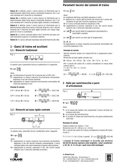
<strong>Parametri</strong> <strong>tecnici</strong> <strong>dei</strong> <strong>sistemi</strong> <strong>di</strong> <strong>traino</strong><br />
x 2<br />
l 2<br />
V = a x x C<br />
dove:<br />
x= lunghezza dell’area caricabile espressa in metri;<br />
l= <strong>di</strong>stanza tra il centro dell’occhione del timone <strong>ed</strong> il centro dell’assieme<br />
<strong>di</strong> assi del rimorchio espressa in metri;<br />
V= è il carico verticale <strong>di</strong>namico espresso in kN;<br />
C= rappresenta la somma, espressa in ton, <strong>dei</strong> carichi assiali<br />
massimi che il rimorchio trasmette al terreno;<br />
m<br />
a = 1,8 per veicoli dotati <strong>di</strong> sospensioni pneumatiche o<br />
s<br />
assimilabili a queste;<br />
2<br />
m<br />
a = 2,4 per veicoli con altro tipo <strong>di</strong> sospensione.<br />
s 2<br />
S = R - C<br />
R=rappresenta la massa massima tecnicamente ammissibile del<br />
rimorchio espressa in ton.<br />
Esempio <strong>di</strong> calcolo<br />
Veicolo trainante isolato con massa=20 ton e sospensioni pneumatiche.<br />
Rimorchio ad asse rigido centrale con:<br />
R = 20 ton C = 19 ton S = 1 ton X = 7.2 m L = 6 m<br />
Per il calcolo del valore Dc si dovrà considerare la massa della<br />
motrice pari a:<br />
T = 20 + S = 20 + 1 = 21 ton<br />
e quin<strong>di</strong><br />
7.2<br />
Dc = = 98 kN V = 1.8 x( x 19 = 49.2 kN<br />
6 ) 2<br />
9.81 x (21 x 19)<br />
21 + 19<br />
2 - Ralle per semirimorchio e perni<br />
<strong>di</strong> articolazione<br />
Fig. 3<br />
D = g x<br />
dove:<br />
0,6 x T x R<br />
T + R - U<br />
T = è la massa del trattore che comprende il carico verticale trasmesso<br />
sulla ralla;<br />
R = è la massa del semirimorchio;<br />
U= è la parte <strong>di</strong> massa del semirimorchio che grava <strong>di</strong>rettamente<br />
sulla ralla.<br />
Esempio <strong>di</strong> calcolo<br />
Trattore isolato con massa = 7 ton<br />
Rimorchio con: R = 36 ton e U = 14 ton<br />
Per il calcolo del valore D si dovrà considerare la massa del trattore<br />
pari a<br />
T = 7 + U = 7 + 14 = 21 ton e quin<strong>di</strong>: D = g x 0,6 x 21 x 36 =101 kN<br />
21 + 36 - 14<br />
I <strong>sistemi</strong> <strong>di</strong> <strong>traino</strong> omologati in accordo alla <strong>di</strong>rettiva<br />
94/20/CE devono riportare sulla targhetta i valori caratteristici<br />
(D, Dc, S, V e U) per i quali sono stati omologati.<br />
V. Orlan<strong>di</strong> S.p.A.<br />
25020 Flero (Bs) Italy - Via Quinzano, 3<br />
Tel. ++39-030-358.27.22 - Fax ++39-030-358.22.62<br />
E-mail: orlan<strong>di</strong>@orlan<strong>di</strong>.it - http://www.orlan<strong>di</strong>.it
D-value: Theoretical load for the determination of the theoretical<br />
horizontal dynamic force between towing vehicle and steering axle<br />
trailer;<br />
Dc-value: Theoretical load for the determination of the theoretical<br />
horizontal dynamic force between towing vehicle and central axle<br />
trailer;<br />
V-value: Theoretical load for the determination of the theoretical<br />
vertical dynamic force between towing vehicle and central axle<br />
trailer of more than 3,5 tons weight;<br />
S-value: Static vertical load transmitt<strong>ed</strong> to the coupling by central<br />
axle trailer in static con<strong>di</strong>tions;<br />
U-value: Vertical load transmitt<strong>ed</strong> to the fifth wheel by the<br />
semitrailer.<br />
1 - Trailer couplings and drawbar eyes<br />
1.1 - Steering axle trailers<br />
Fig. 1<br />
In this case the technical parameter is following:<br />
D = g x<br />
T x R<br />
T + R<br />
where:<br />
g = Gravitational acceleration; 9.81 m/s 2 ;<br />
T= Technically admissible maximum weight of towing vehicle in<br />
tons;<br />
R= Technically admissible maximum weight of trailer in tons.<br />
Examples of calculation<br />
a) T = 18 ton; R = 26 ton D =<br />
9.81 x (18 x 26)<br />
18 + 26<br />
= 104.3 kN<br />
b) T = 14 ton; R = 42 ton D =<br />
9.81 x (14 x 42)<br />
14 + 42<br />
= 103.1 kN<br />
c) T = 30 ton; R = 50 ton D =<br />
9.81 x (30 x 50)<br />
30 + 50<br />
= 183.9 kN<br />
1.2 - Central axle trailers<br />
Fig. 2<br />
In this case the technical parameter is following:<br />
T x C<br />
Dc = g x<br />
T + C<br />
where:<br />
T= Technically admissible maximum load of the towing vehicle in<br />
tons, inclu<strong>di</strong>ng the static vertical load transmitt<strong>ed</strong> to the<br />
coupling by the drawbar eye;<br />
C= Sum of the maximum axle loads transmitt<strong>ed</strong> to the ground by<br />
the trailer in tons.<br />
Technical parameters of towing system<br />
x 2<br />
l 2<br />
V = a x x C<br />
where:<br />
x= Length of the loa<strong>di</strong>ng area in meters;<br />
l= <strong>di</strong>stance between the center of the hole of the drawbar eye<br />
and the center of the axles of the trailer in meters;<br />
V= Dynamic vertical load in kN;<br />
C= Sum of the maximum axial loads transmitt<strong>ed</strong> to the ground by<br />
the trailer in tons;<br />
m<br />
a = 1,8 for vehicles with air suspensions or with a<br />
s<br />
comparable suspension type;<br />
2<br />
m<br />
a = 2,4 for vehicle with other types of suspensions.<br />
s 2<br />
S = R - C<br />
R=Technically admissible maximum weight of the trailer in tons.<br />
Example of calculation<br />
Towing vehicle with 20 tons weight and with air suspensions.<br />
Central axle trailer with:<br />
R = 20 ton C = 19 ton S = 1 ton X = 7.2 m L = 6 m<br />
For the determination of the Dc-value the weight of the towing<br />
vehicle is calculat<strong>ed</strong> as follows:<br />
T = 20 + S = 20 + 1 = 21 ton<br />
and therefore<br />
7.2<br />
Dc = = 98 kN V = 1.8 x( x 19 = 49.2 kN<br />
6 ) 2<br />
9.81 x (21 x 19)<br />
21 + 19<br />
2 - Fifth wheels and kingpins<br />
Fig. 3<br />
D = g x<br />
where:<br />
0,6 x T x R<br />
T + R - U<br />
T = Weight of the towing vehicle inclu<strong>di</strong>ng the vertical load on the<br />
fifth wheel;<br />
R = Weight of the semitrailer;<br />
U= That part of the semitrailer weight which is <strong>di</strong>rectly transmitt<strong>ed</strong><br />
to the fifth wheel.<br />
Example of calculation<br />
Towing vehicle alone, weight 7 tons<br />
Trailer with R = 36 tons and U = 14 tons<br />
For the determination of the D-value the weight of the towing<br />
vehicle is calculat<strong>ed</strong> as follows:<br />
T = 7 + U = 7 + 14 = 21 ton and therefore<br />
0,6 x 21 x 36<br />
D = g x =101 kN<br />
21 + 36 - 14<br />
The towing systems homologat<strong>ed</strong> accor<strong>di</strong>ng to the <strong>di</strong>rective<br />
94/20/EC have to bear in the homologation plate the<br />
characteristic values (D, Dc, S, V and U) accor<strong>di</strong>ng to which<br />
they have been approv<strong>ed</strong>.
D-Wert: Theoretische Deichselkraft, basierend auf einem<br />
rechnerischen Bezugswert von Zugfahrzeug und<br />
Drehschemelanhänger;<br />
Dc-Wert: Theoretische Deichselkraft, basierend auf einem<br />
rechnerischen Bezugswert von Zugfahrzeug und<br />
Zentralachsanhänger;<br />
V-Wert: Theoretische vertikale Belastung durch<br />
Zentralachsanhänger von mehr als 3,5 t. zulässigem<br />
Gesamtgewicht abhängig von der Hinterachsf<strong>ed</strong>erung des<br />
Zugfahrzeuges;<br />
S-Wert: Statische vertikale Belastung, durch den<br />
Zentralachsanhänger auf den Kuppelpunkt;<br />
U-Wert: Vertikale Belastung vom Auflieger auf <strong>di</strong>e Sattelkupplung.<br />
1 - Anhängekupplungen und Zugösen<br />
1.1 - Drehschemelanhänger<br />
Fig. 1<br />
In <strong>di</strong>esem Fall sind <strong>di</strong>e technischen Kennwerte wie folgt:<br />
D = g x<br />
wobei:<br />
g = Erdbeschleunigung: 9.81 m/s2 T x R<br />
T + R<br />
;<br />
T= Maximales zulässiges Gesamtgewicht des Zugfahrzeuges in t;<br />
R= Maximales zulässiges Gesamtgewicht des<br />
Drehschemelanhängers in t.<br />
Kalkulationsbeispiele<br />
9.81 x (18 x 26)<br />
a) T = 18 ton; R = 26 ton D = = 104.3 kN<br />
18 + 26<br />
9.81 x (14 x 42)<br />
b) T = 14 ton; R = 42 ton D = = 103.1 kN<br />
14 + 42<br />
9.81 x (30 x 50)<br />
c) T = 30 ton; R = 50 ton D = = 183.9 kN<br />
30 + 50<br />
1.2 - Zentralachsanhänger<br />
Fig. 2<br />
In <strong>di</strong>esem Fall sind <strong>di</strong>e technischen Kennwerte wie folgt:<br />
T x C<br />
Dc = g x<br />
T + C<br />
wobei:<br />
T= Zulässiges Gesamtgewicht des Zugfahrzeuges inklusive<br />
statische Stützlast, <strong>di</strong>e von der Zugöse auf <strong>di</strong>e Kupplung wirkt,<br />
in t;<br />
C= Summe der maximalen Achslasten, <strong>di</strong>e vom Anhänger<br />
übertragen werden, in t.<br />
Technische Kennwerte der<br />
Verbindungseinrichtungen<br />
x 2<br />
l 2<br />
V = a x x C<br />
wobei:<br />
x= Länge der Ladefläche in m;<br />
l= Distanz zwischen dem Mittelpunkt der Zugöse und dem der<br />
Anhängerachsen, in m;<br />
V= Dynamische Vertikallast in kN;<br />
C=Summe der maximalen Achslasten, <strong>di</strong>e vom Anhänger<br />
übertragen werden, in t;<br />
m<br />
a = 1,8 für Fahrzeuge mit Luftf<strong>ed</strong>erung oder einer<br />
s<br />
vergleichbaren F<strong>ed</strong>erung;<br />
2<br />
m<br />
a = 2,4 für Fahrzeuge mit anderer F<strong>ed</strong>erung.<br />
s 2<br />
S = R - C<br />
R=Maximales, technisch zulässiges Gesamtgewicht des<br />
Anhängers in t.<br />
Kalkulationsbeispiel<br />
Zugfahrzeug mit 20 t zulässigem Gesamtgewicht mit<br />
Luftf<strong>ed</strong>erung.<br />
Zentralachsanhänger mit:<br />
R = 20 ton C = 19 ton S = 1 ton X = 7.2 m L = 6 m<br />
Um den Dc-Wert zu errechnen wird das Gesamtgewicht des<br />
Zugfahrzeuges wie folgt ermittelt:<br />
T = 20 + S = 20 + 1 = 21 ton<br />
Daraus folgt<br />
7.2<br />
Dc = = 98 kN V = 1.8 x( x 19 = 49.2 kN<br />
6 ) 2<br />
9.81 x (21 x 19)<br />
21 + 19<br />
2 - Sattelkupplungen und Zugsattelzapfen<br />
Fig. 3<br />
D = g x<br />
wobei:<br />
0,6 x T x R<br />
T + R - U<br />
T = Gesamtgewicht des Zugfahrzeuges zuzüglich Vertikallast auf<br />
<strong>di</strong>e Sattelkupplung;<br />
R = Gesamtgewicht des Aufliegers;<br />
U= Anteil des Aufliegergewichtes, das <strong>di</strong>rekt auf <strong>di</strong>e<br />
Sattelkupplung übertragen wird.<br />
Kalkulationsbeispiel<br />
Zugfahrzeuggewicht = 7 ton<br />
Auflieger mit R = 36 ton und U = 14 ton<br />
Um den D-Wert zu errechnen, wird das Gewicht des Zugfahrzeuges<br />
berücksichtigt:<br />
T = 7 + U = 7 + 14 = 21 ton und deshalb ist:<br />
D = g x<br />
0,6 x 21 x 36<br />
=101 kN<br />
21 + 36 - 14<br />
Die Kupplungssysteme, <strong>di</strong>e nach 94/20/EG homologiert sind,<br />
müssen im Typenschild <strong>di</strong>e characteristischen Werte (D, Dc,<br />
S, V und U) tragen, nach denen sie geprüft sind.
Valeur D: La charge théorique de référence pour déterminer la<br />
force théorique horizontale dynamique que le véhicule trainant<br />
ainsi que la remorque s’échangent;<br />
Valeur Dc: La charge théorique de référence pour déterminer la<br />
force théorique horizontale dynamique que le véhicule trainant<br />
ainsi que la remorque aux essieux centrales s’échangent;<br />
Valeur V: La charge théorique de référence pour déterminer la<br />
force théorique verticale dynamique que le véhicule trainant ainsi<br />
que la remorque aux essieux centrales et avec une masse<br />
supérieure à 3,5 tonnes s’échangent;<br />
Valeur S: La charge verticale statique que la remorque aux<br />
essieux centrales transmet au crochet dans des con<strong>di</strong>tions<br />
statiques;<br />
Valeur U: La charge verticale transmise par la semi-remorque à la<br />
sellette.<br />
1 - Les crochets et les anneaux d’attelages<br />
1.1 - Les remorques tra<strong>di</strong>tionnelles<br />
Fig. 1<br />
Dans ce cas, le paramètre technique est le suivant:<br />
D = g x<br />
là où:<br />
g = l’accélération de la gravité: 9.81 m/s2 T x R<br />
T + R<br />
;<br />
T= La masse maximum techniquement admissible, exprimée en<br />
tonnes du véhicule trainant;<br />
R= La masse maximum techniquement admissible de la<br />
remorque, exprimée en tonnes.<br />
Exemples de calcul:<br />
a) T = 18 ton; R = 26 ton D =<br />
9.81 x (18 x 26)<br />
18 + 26<br />
= 104.3 kN<br />
b) T = 14 ton; R = 42 ton D =<br />
9.81 x (14 x 42)<br />
14 + 42<br />
= 103.1 kN<br />
c) T = 30 ton; R = 50 ton D =<br />
9.81 x (30 x 50)<br />
30 + 50<br />
= 183.9 kN<br />
1.2 - Les remorques aux essieux centrales<br />
Fig. 2<br />
Dans ce cas les paramètres techniques sont les suivants:<br />
T x C<br />
Dc = g x<br />
T + C<br />
là où:<br />
T= La masse maximum techniquement admissible, exprimée en<br />
tonnes, du véhicule trainant avec y compris la charge du<br />
véhicule statique qui est transmise au crochet par l’anneau<br />
de remorquage;<br />
C= La somme exprimée en tonnes, charges axiales maximum que<br />
la remorque transmet au terrain.<br />
Les parametres techniques<br />
des system de traction<br />
x 2<br />
l 2<br />
V = a x x C<br />
là où:<br />
x= La longueur de l’aire chargeable exprimée en mètres;<br />
l= La <strong>di</strong>stance entre le centre de l’anneau de remorquage du<br />
gouvernail et le centre de l’ensemble des assieux de la<br />
remorque exprimée en mètres;<br />
V= La charge verticale dynamique exprimée en kN;<br />
C= La somme, exprimée en tonnes, des charges axiales<br />
maximum que la remorque transmet au train;<br />
a = 1,8<br />
m<br />
pour les véhicules avec suspensions<br />
s pneumatiques;<br />
2<br />
a = 2,4<br />
m<br />
pour les véhicules ayant un autre type de<br />
s<br />
suspensions.<br />
2<br />
S = R - C<br />
R=La masse maximum techniquement admissible pour la<br />
remorque et elle est exprimée en tonnes.<br />
Un exemple de calcul<br />
Le véhicule trainant indépendant avec une masse égale à 20<br />
tonnes et des suspensions pneumatiques.<br />
Une remorque aux essieux centrales et avec:<br />
R = 20 ton C = 19 ton S = 1 ton X = 7.2 m L = 6 m<br />
Pour calculer la valeur Dc, il faudra considérer la masse de la<br />
motrice égale à:<br />
T = 20 + S = 20 + 1 = 21 ton<br />
et donc<br />
7.2<br />
Dc = = 98 kN V = 1.8 x( x 19 = 49.2 kN<br />
6 ) 2<br />
9.81 x (21 x 19)<br />
21 + 19<br />
2 - Les sellettes et les pivots d’attelage<br />
Fig. 3<br />
D = g x<br />
là où:<br />
0,6 x T x R<br />
T + R - U<br />
T = La masse du tracteur qui comprend la charge verticale<br />
transmise sur la sellette;<br />
R = La masse de la semi-remorque;<br />
U= La partie de la masse de la semi- remorque qui pèse<br />
<strong>di</strong>rectement sur la sellette.<br />
Un exemple de calcul<br />
Tracteur avec masse 7 tonnes<br />
Semi-remorque avec: R = 36 tonnes et U = 14 tonnes<br />
Pour effectuer le calcul de la valeur D il faudra considérer la<br />
masse du tracteur égale à:<br />
T = 7 + U = 7 + 14 = 21 ton et donc: D = g x<br />
0,6 x 21 x 36<br />
=101 kN<br />
21 + 36 - 14<br />
Les systèmes d’attelage homologués en accord avec les<br />
<strong>di</strong>rectives 94/20/CE doivent reporter sur la plaque les valeurs<br />
caractéristiques (D, Dc, S, V et U) pour lesquels ils ont été<br />
homologués.<br />
Subject to technical changes without prior notice<br />
1990 096 A