microCLIMA DE-08-MI004-PTB014 / 22.75/08.03
microCLIMA DE-08-MI004-PTB014 / 22.75/08.03
microCLIMA DE-08-MI004-PTB014 / 22.75/08.03
Create successful ePaper yourself
Turn your PDF publications into a flip-book with our unique Google optimized e-Paper software.
7 Calculator Settings<br />
7.1 Optical (infrared) interface<br />
In order to be able to communicate with a calculator instrument,<br />
an optocoupler must be connected to the USB-interface or to the<br />
serial interface of the PC. The optocoupler and the software are<br />
available as options.<br />
The optical (infrared) interface is activated by pressing the<br />
pushbutton.<br />
If within 60 seconds neither a valid telegram is received now the<br />
pushbutton pressed again, then the interface is deactivated.<br />
7.2 M-bus interface<br />
An M-bus interface is also available as a built-in option for the<br />
calculator (must be stated when ordering).<br />
A calculator with an M-bus interface is supplied with power via the<br />
M-bus network (no galvanic separation). The number of read-outs<br />
via the M-bus interface per instrument per day is unlimited.<br />
The valid standards for the M-bus protocol are EN13757-2 and<br />
13757-3.<br />
Notes on installation:<br />
• Each end instrument is only protected against high voltage<br />
up to the maximal allowed bus voltage (±50V). Additional<br />
protective measures must be provided by the level converter.<br />
• The installation of an instrument in an M-bus network may<br />
only be carried out by authorized, qualifi ed technical<br />
personnel.<br />
• Attention must be paid to ensure that the cable lengths and<br />
cable cross-sections in the bus network are appropriate for<br />
the baud rate of the end instrument (2400 baud).<br />
• Recommended cable type:<br />
Telephone cable J-Y(ST) Y2 x 2 x 0.8 mm²<br />
Calculators with the M-bus option can be addressed primarily or<br />
secondarily.<br />
Both addresses can be set via the optical interface using the<br />
software. They can also be set using the display.<br />
The primary address is the M-bus address displayed in the 2nd<br />
level (technician’s loop) in menu item 6) ‘M-bus address (primary<br />
address)’.<br />
The secondary address is the customer identifi cation no. and can<br />
be selected under menu item 9) ‘Selectable customer-set<br />
calculator no.’ ‚ in the fi rst level (the main loop).<br />
If a customer no. has not been identifi ed, the serial no. is<br />
displayed. This is the factory setting.<br />
8 Calculator Settings<br />
8.1 Pulse value (TX version)<br />
For version TX instruments the pulse value can be set at the<br />
beginning of operation.<br />
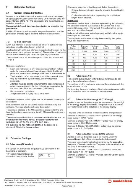
TX version instruments can be<br />
recognized by a special display.<br />
Maddalena S.p.A., Via G.B. Maddalena, 2/4, 33040 Povoletto (UD) - Italy<br />
Tel.: +39 0432 634811, Fax.: +39 0432.679007, Fax Export: 39 0432.679820 ,www.maddalena.it<br />
Article-No. 1<strong>08</strong>0700011 - 2012-02-01 Pagina/Page 13<br />
If the pulse value has not yet been set, follow these steps:<br />
• Choose the desired pulse value by pressing the pushbutton<br />
briefl y.<br />
• Confi rm the selected value by pressing the pushbutton<br />
longer than 4 seconds.<br />
Important:<br />
As soon as the fi rst input pulses are registered by the calculator,<br />
the calculator fi xes the pulse value at the value it has at that<br />
moment (factory setting 1liter/pulse). This value is then permanent<br />
and cannot be changed.<br />
Make sure that the pulse value is properly set before the equipment<br />
is put into operation.<br />
The display format is automatically determined by the pulse<br />
value that has been set:<br />
Pulse<br />
[l/Imp.]<br />
Energy<br />
[MWh]<br />
Volume<br />
[m 3 ]<br />
Flow<br />
[m 3 /h]<br />
Power<br />
[kW]<br />
1 0,000 0,000 0,000 0,000<br />
2,5 0,00 0,00 0,00 0,00<br />
10 0,00 0,00 0,00 0,00<br />
25 0,0 0,0 0,0 0,0<br />
100 0,0 0,0 0,0 0,0<br />
250 0 0 0 0<br />
1000 0 0 0 0<br />
8.2 Pulse inputs 1+2<br />
The optional pulse inputs 1+2 for external meters can be set<br />
using the confi guration software.<br />
The settings are the input pulse value and the units in which the<br />
external meter counts.<br />
For invoicing, the meter readings of the instruments connected to<br />
the pulse inputs must be included in the calculation.<br />
8.3 Pulse output for energy (OUT1-Energy)<br />
A pulse is sent via the pulse output for energy when the last digit<br />
of the energy display is increased. The pulse value is automatically<br />
determined by the last place of the energy display.<br />
The pulse units are identical to the units of the energy display:<br />
Example 1: Display 12345678 kWh => pulse value for energy<br />
pulse output = 1 kWh / pulse<br />
Example 2: Display 12345,678 MWh => pulse value for energy<br />
pulse output = 0.001 MWh / pulse<br />
Example 3: Display 1234567,8 GJ => pulse value for energy<br />
pulse output = 0.1 GJ / pulse<br />
8.4 Pulse output for volume (OUT2-Volume)<br />
A pulse is sent via the pulse output for volume, when the<br />
second-to-last digit of the volume display is increased.<br />
The pulse value is automatically determined by the second-tolast<br />
place of the volume display. The pulse units are identical to<br />
the units of the volume display.<br />
Example 1: Display 12345,678 m 3 => pulse value for volume<br />
pulse output = 0.01 m 3 / pulse<br />
Example 2: Display 12345678 l => pulse value for volume pulse<br />
output = 10 l / pulse


