CAVEX® - MOTOR-GEAR as
CAVEX® - MOTOR-GEAR as
CAVEX® - MOTOR-GEAR as

Create successful ePaper yourself
Turn your PDF publications into a flip-book with our unique Google optimized e-Paper software.
CAVEX<br />
Schneckengetriebe Worm Gear Units Réducteurs à vis sans fin<br />
Anbauanleitung und Befestigung Installation Instructions, F<strong>as</strong>tening Montage et de fixation pour<br />
von Aufsteckgetrieben of Shaft-mounted Worm Gear Units réducteurs flottants<br />
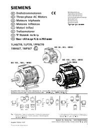
Kräfte an einem CAVEX-Aufsteckgetriebe,<br />
Bauart CDA<br />
F1 = Kraft aus dem Gewicht des Aufsteckgetriebes<br />
auf die M<strong>as</strong>chinenwelle<br />
n2 = Drehrichtung der Hohlwelle D2 TR = Reaktionsdrehmoment am Getriebegehäuse<br />
= Abtriebsdrehmoment T2 FS = Abstützkraft von der Drehmomentstütze<br />
auf die Aufhängung<br />
F2 = Kraft auf die M<strong>as</strong>chinenwelle<br />
= Kraft FS *) Die Bohrungstoleranz H7 in der Hohlwelle<br />
ist ein Mittelwert. Um einerseits d<strong>as</strong> Aufziehen<br />
des Getriebes zu erleichtern, andererseits<br />
aber einen festen Sitz auf der Welle<br />
zu erreichen, ist die Bohrungstoleranz bis<br />
G7 erweitert, in der Mitte des Paßsitzes<br />
wird die Bohrung enger bis J7. In Hohlwellenmitte<br />
ist auf etwa 1/3 der Gesamtlänge<br />
eine Aussparung vorhanden.<br />
Anbauanleitung für Aufsteckgetriebe<br />
Zweckmäßig erfolgt die Abstützung des Drehmomentes<br />
über Bolzen und L<strong>as</strong>chen, damit d<strong>as</strong><br />
Getriebe verspannunsfrei bleibt.<br />
Bei Verformungen der M<strong>as</strong>chinenwelle ist der<br />
dadurch hervorgerufene Kupplungsversatz an<br />
der Antriebswelle zu beachten. Es empfiehlt sich,<br />
den Motor anzuflanschen.<br />
Befestigung der CAVEX-Aufsteckgetriebe<br />
D<strong>as</strong> Wellenende der anzutreibenden Arbeitsm<strong>as</strong>chine<br />
muß mit Paßfeder nach DIN 6885 / 1 ausgeführt<br />
sein und sollte stirnseitig eine Zentrierung<br />
Form DS nach DIN 332 haben. Wir empfehlen die<br />
Befestigung des Getriebes mit einer Endscheibe,<br />
die auch als Abdrückhilfe benutzt werden kann.<br />
Zu diesem Zweck haben alle Hohlwellen eine<br />
Seegerring-Nut nach DIN 472.<br />
Um ein Abziehen der Aufsteckgetriebe zu erleichtern,<br />
empfehlen wir, im Wellenende der Arbeitsm<strong>as</strong>chine<br />
vor der Montage eine Bohrung gemäß<br />
obenstehender Abbildung vorzusehen. Durch<br />
diese Bohrung soll nach Anschluß eines Injektors<br />
im Bedarfsfall Rostlöser an den Radkörpersitz<br />
gebracht werden können. Hierzu ist es erforderlich,<br />
daß die Querbohrung im Bereich der Ausdrehung<br />
der Hohlwelle mündet.<br />
K88 DE/EN/FR<br />
Druckölanschluß<br />
Pressure oil connection<br />
Connection d’huile sous pression<br />
Forces acting on a shaft-mounted CAVEX<br />
gear unit type CDA<br />
F1 = Force resulting from the weight of the<br />
gear unit on the machine shaft<br />
n2 = Direction of rotation of hollow shaft D2 TR = Reaction torque on gear housing = output<br />
torque T2 FS = Torque support arm force acting on<br />
suspension<br />
F2 = Force on driven machine shaft<br />
= force FS *) The hollow shaft tolerance H7 is a mean<br />
value. In order to facilitate mounting of gear<br />
units and still obtain a tight shaft fit, the<br />
tolerance h<strong>as</strong> been widened to G7 at the<br />
ends of the hollow shaft, while the centre of<br />
the fit narrows to J7. The centre part of the<br />
hollow shaft is recessed over approximately<br />
1/3 of its total length.<br />
Installation instructions for shaft-mounted<br />
gear units<br />
The most functional torque support is with a<br />
damping and flexible suspension.<br />
Deformations of the machine shaft cause<br />
coupling misalignment on the input shaft and<br />
should be taken into account; a flanged motor is<br />
recommended.<br />
F<strong>as</strong>tening of shaft-mounted CAVEX worm<br />
gear units<br />
The shaft end of the driven machine should have<br />
a parallel key acc. to DIN 6885 sheet 1, and a<br />
tapped centre hole acc. to DIN 332, form DS. We<br />
recommend to f<strong>as</strong>ten the gear unit with an end<br />
plate which can also be used <strong>as</strong> a forcing plate.<br />
For this purpose, all hollow shafts are furnished<br />
with ring grooves for circlips acc. to DIN 472.<br />
To facilitate pulling off of the mounted gear units at<br />
a later stage we recommend to drill a hole into the<br />
shaft end of the driven machine before fitting the<br />
gear unit, see illustration above. By means of an<br />
injector fitted to the hole, rust solvent can be<br />
brought to the shaft seat through it, if necessary.<br />
To accomplish this, it will, of course, be necessary<br />
for the outlet of the vertical bore to be within the<br />
recessed part of the hollow shaft.<br />
*<br />
Schéma des forces agissant sur un réducteur<br />
”flottant” CAVEX type CDA<br />
F1 = Force agissant sur l’arbre de la machine<br />
provenant du poids du réducteur<br />
n2 = Sens de rotation de l’arbre creux D2 TR = Couple de réaction sur le carter du<br />
réducteur = couple de sortie T2 FS = Force au point de suspension du br<strong>as</strong><br />
de réaction<br />
F2 = Force appliquée sur l’arbre de la machine<br />
= force FS *) La tolérance H7 dans l’arbre creux est une<br />
valeur moyenne. Pour faciliter le montage<br />
et garantir néanmoins un ajustement serré,<br />
elle est élargie jusqu’ à G7 aux extrémités<br />
et réduite jusqu’à J7 vers le centre. Un évidement<br />
est prévu au milieu de l’arbre creux<br />
sur 1/3 de la longueur totale environ.<br />
Instructions de montage des réducteurs<br />
flottants<br />
Il est utille de suspendre le br<strong>as</strong> de réaction par<br />
l’intermédiaire d’un organe él<strong>as</strong>tique absorbant.<br />
On empêche ainsi les tensions dans la transmission.<br />
Une déformation de l’arbre de la machine peut<br />
provoquer un désalignement de l’accouplement à<br />
l’arbre d’entrée. Il est recommandé d’utiliser un<br />
moteur à bride.<br />
Fixation des réducteurs CAVEX flottants<br />
Le bout d’arbre de la machine entraînée doit être<br />
exécuté avec clavette selon DIN 6885 feuille 1 et<br />
devra comporter un centrage de forme D5, selon<br />
DIN 332. Nous conseillons de fixer le réducteur à<br />
l’aide d’une rondelle de fixation, qui peut servir<br />
également de rondelle de démontage. Pour cette<br />
raison, tous les arbres creux possèdent une<br />
rainure de circlips selon DIN 472.<br />
Après plusieurs années de service, l’influence du<br />
temps, de l’atmosphère ambiante et de la rouille<br />
de contact peuvent rendre le démontage difficile.<br />
Afin de faciliter le démontage, nous conseillons<br />
de prévoir dans le bout d’arbre de la machine un<br />
perçage tel qu’il est représenté ci-dessus. Si besoin<br />
est, on doit pouvoir introduire, par ce trou, un<br />
injecteur permettant de pulvériser un produit antirouille<br />
à l’intérieur du moyeu de la roue. Il est donc<br />
nécessaire qu’un alésage radial aboutisse dans<br />
l’embrèvement du moyeu.<br />
101