Aermec: Fancoil for the vertical or horizontal installation with ...
Aermec: Fancoil for the vertical or horizontal installation with ...
Aermec: Fancoil for the vertical or horizontal installation with ...

You also want an ePaper? Increase the reach of your titles
YUMPU automatically turns print PDFs into web optimized ePapers that Google loves.
Ventilconvett<strong>or</strong>e per installazione <strong>vertical</strong>e o <strong>or</strong>izzontale con depurat<strong>or</strong>e PLASMACLUSTER®<br />
<strong>Fancoil</strong> <strong>f<strong>or</strong></strong> <strong>the</strong> <strong>vertical</strong> <strong>or</strong> h<strong>or</strong>izontal <strong>installation</strong> <strong>with</strong> PLASMACLUSTER® purifier<br />
Ventilo-convecteur pour <strong>installation</strong> <strong>vertical</strong>e ou h<strong>or</strong>izontale avec dépurateur PLASMACLUSTER®<br />
Gebläsekonvekt<strong>or</strong> zur vertikalen oder h<strong>or</strong>izontalen Installation mit Reinigungsapparat PLASMACLUSTER®<br />
Fan coil para instalaciones <strong>vertical</strong>es u h<strong>or</strong>izontales con depurad<strong>or</strong> PLASMACLUSTER®<br />
FCX APC<br />
ISO 9001 - Cert. n° 0128/4<br />
MANUALE D’USO E INSTALLAZIONE<br />
USE AND INSTALLATION MANUAL<br />
MANUEL D'UTILISATION ET D'INSTALLATION<br />
BEDIENUNGS- UND INSTALLATIONSANLEITUNG<br />
MANUAL DE INSTRUCCIONES E INSTALACIÓN<br />
IFCXAPCLJ<br />
0711<br />
6456059_02<br />
Sostituisce il Replace Remplace le n° Ersetzt Sustituye a: 64560.59_01 / 0703
Italiano<br />
English<br />
Español Deutsche<br />
Français<br />
OSSERVAZIONI<br />
Conservare i manuali in luogo asciutto, per evitare il deteri<strong>or</strong>amento,<br />
per almeno 10 anni per eventuali riferimenti futuri.<br />
Leggere attentamente e completamente tutte le in<strong>f<strong>or</strong></strong>mazioni<br />
contenute in questo manuale. Prestare particolarmente<br />
attenzione alle n<strong>or</strong>me d’uso accompagnate dalle scritte<br />
“PERICOLO” o “ATTENZIONE” in quanto, se non osservate,<br />
possono causare danno alla macchina e/o a persone e cose.<br />
Per anomalie non contemplate da questo manuale, interpellare<br />
tempestivamente il Servizio Assistenza di zona.<br />
L'apparecchio deve essere installato in maniera tale da rende-<br />
REMARKS<br />
St<strong>or</strong>e <strong>the</strong> manuals in a dry location to avoid deteri<strong>or</strong>ation, as<br />
<strong>the</strong>y must be kept <strong>f<strong>or</strong></strong> at least 10 years <strong>f<strong>or</strong></strong> any future reference.<br />
All <strong>the</strong> in<strong>f<strong>or</strong></strong>mation in this manual must be carefully read and<br />
understood. Pay particular attention to <strong>the</strong> operating standards<br />
<strong>with</strong> “DANGER” <strong>or</strong> “WARNING” signals as failure to<br />
comply <strong>with</strong> <strong>the</strong>m can cause damage to <strong>the</strong> machine and/<strong>or</strong><br />
persons <strong>or</strong> objects.<br />
If any malfunctions are not included in this manual, contact<br />
<strong>the</strong> local After-sales Service immediately.<br />
The apparatus must be installed in such a way that maintenan-<br />
REMARQUES<br />
Conserver les manuels dans un endroit sec, afin d’éviter leur<br />
détéri<strong>or</strong>ation, pendant au moins 10 ans, pour toutes éventuelles<br />
consultations futures.<br />
Lire attentivement et entièrement toutes les in<strong>f<strong>or</strong></strong>mations contenues<br />
dans ce manuel. Prêter une attention particulière aux<br />
n<strong>or</strong>mes d’utilisation signalées par les inscriptions “DANGER”<br />
ou “ATTENTION”, car leur non observance pourrait causer un<br />
dommage à l’appareil et/ou aux personnes et objets.<br />
Pour toute anomalie non mentionnée dans ce manuel, contacter<br />
aussitôt le service après-vente de votre secteur.<br />
L<strong>or</strong>s de l'<strong>installation</strong> de l'appareil, il faut prévoir l'espace<br />
HINWEISE<br />
Bewahren Sie die Gebrauchsanleitungen mindestens<br />
10 Jahre für eventuelles zukünftiges<br />
Nachschlagen an einem trockenen Ort auf.<br />
Alle in diesem Handbuch enthaltenen In<strong>f<strong>or</strong></strong>mationen<br />
aufmerksam und vollständig lesen. Insbesondere auf die<br />
Benutzungsanweisungen mit den Hinweisen "VORSICHT"<br />
oder "ACHTUNG" achten, da deren Nichtbeachtung Schäden<br />
am Gerät bzw. Sach- und Personenschäden zur Folge haben<br />
kann.<br />
Bei Betriebsstörungen, die in dieser Gebrauchsanweisung nicht<br />
aufgeführt sind, wenden Sie sich umgehend an die zuständige<br />
OBSERVACIONES<br />
Guarde los manuales en un lugar seco para evitar su deteri<strong>or</strong>o,<br />
al menos durante 10 años, p<strong>or</strong> si fuera posible consultarlos en<br />
el futuro.<br />
Leer atenta y completamente todas las in<strong>f<strong>or</strong></strong>maciones contenidas<br />
en este manual. Preste particular atención a las n<strong>or</strong>mas<br />
de uso acompañadas de las indicaciones “PELIGRO” o<br />
“ATENCIÓN” puesto que, si no se cumplen, pueden causar el<br />
deteri<strong>or</strong>o de la máquina y/o daños personales y materiales.<br />
En caso de anomalías no contempladas en este manual, contacte<br />
inmediatamente con el Servicio de Asistencia de su zona.<br />
El aparato debe ser instalado de manera que haga posibles las<br />
2<br />
re possibili operazioni di manutenzione e/o riparazione.<br />
La garanzia dell'apparecchio non copre in ogni caso i costi<br />
dovuti ad autoscale, ponteggi o altri sistemi di elevazione che<br />
si rendesero necessari per effettuare gli interventi in garanzia.<br />
AERMEC S.p.A. declina ogni responsabilità per qualsiasi danno<br />
dovuto ad un uso improprio della macchina, ad una lettura<br />
parziale o superficiale delle in<strong>f<strong>or</strong></strong>mazioni contenute in questo<br />
manuale.<br />
Il numero di pagine di questo manuale è: 44.<br />
ce and/<strong>or</strong> repair operations are possible.<br />
The apparatus's warranty does not in any case cover costs due<br />
to automatic ladders, scaffolding <strong>or</strong> o<strong>the</strong>r lifting systems necessary<br />
<strong>f<strong>or</strong></strong> carrying out repairs under guarantee.<br />
AERMEC S.p.A. declines all responsibility <strong>f<strong>or</strong></strong> any damage whatsoever<br />
caused by improper use of <strong>the</strong> machine, and a partial<br />
<strong>or</strong> superficial acquaintance <strong>with</strong> <strong>the</strong> in<strong>f<strong>or</strong></strong>mation contained in<br />
this manual.<br />
The number of pages in this manual is : 44.<br />
nécessaire pour les opérations d'entretien et/ou de réparation.<br />
La garantie de l'appareil ne couvre pas les coûts dérivant de<br />
l'utilisation de voitures avec échelle mécanique, d'échafaudages<br />
ou d'autres systèmes de levée employés pour effectuer des<br />
interventions en garantie.<br />
AERMEC S.p.A. décline toute responsabilité pour tout dommage<br />
dû à une utilisation impropre de l’appareil et à une lecture<br />
partielle ou superficielle des in<strong>f<strong>or</strong></strong>mations contenues dans ce<br />
manuel.<br />
Ce manuel se compose de pages: 44.<br />
Kundendienststelle.<br />
Das Gerät so aufstellen, dass Instandhaltungs- und/oder<br />
Reparaturarbeiten durchgeführt werden können.<br />
Die Garantie des Gerätes deckt in keinem Fall Kosten für<br />
Feuerwehrleitern, Gerüste oder andere Hebesysteme ab, die<br />
sich für die Garantiearbeiten als er<strong>f<strong>or</strong></strong>derlich erweisen sollten.<br />
Die AERMEC S.p.A. übernimmt keine Haftung für Schäden aus<br />
dem unsachgemäßen Gebrauch des Gerätes und der teilweisen<br />
oder oberflächlichen Lektüre der in diesem Handbuch enthaltenen<br />
In<strong>f<strong>or</strong></strong>mationen.<br />
Die Seitenanzahl diese Handbuches ist: Nr. 44 Seiten<br />
operaciones de mantenimiento y/o reparación.<br />
En cualquier caso, la garantía del aparato no cubre los costes<br />
derivados del uso de escaleras automáticas, andamios u otros<br />
sistemas de elevación necesarios para efectuar las intervenciones<br />
en garantía.<br />
AERMEC S.p.A. declina cualquier responsabilidad p<strong>or</strong> cualquier<br />
daño debido a un uso impropio de la máquina, o bien a<br />
una lectura parcial o superficial de las in<strong>f<strong>or</strong></strong>maciones contenidas<br />
en este manual.<br />
Número de páginas de este manual: 44.
INDICE<br />
DICHIARAZIONE DI CONFORMITÀ<br />
Trasp<strong>or</strong>to Simboli di sicurezza<br />
Descrizione di FCX APC<br />
Utilizzo Visualizzazioni<br />
In<strong>f<strong>or</strong></strong>mazioni imp<strong>or</strong>tanti e manutenzione Plasmacluster Imballo<br />
Caratteristiche di funzionamento Installazione dell’unità<br />
Collegamenti elettrici Rotazione batteria<br />
Autotest Configurazione Dip<br />
Dati dimensionali<br />
Disegni<br />
Schema elettrico<br />
SOLUZIONE DEI PROBLEMI<br />
SERVIZIO ASSISTENZA TECNICA IN ITALIA<br />
INDEX<br />
DECLARATION OF CONFORMITY<br />
Carriage Safety symbol<br />
Description of <strong>the</strong> FCX APC<br />
Use Displays<br />
Imp<strong>or</strong>tant in<strong>f<strong>or</strong></strong>mation and maintenance Plasmacluster Packaging<br />
Operating characteristics Unit <strong>installation</strong><br />
Electrical connections Battery rotation<br />
Autotest Configuration Dip<br />
Dimensions<br />
Sketches<br />
Wiring diagram<br />
TROUBLE SHOOTING<br />
INDEX<br />
CERTIFICAT DE CONFORMITE<br />
Transp<strong>or</strong>t Simboles de securite<br />
Description d'FCX APC<br />
Utilisation Affichages<br />
In<strong>f<strong>or</strong></strong>mations imp<strong>or</strong>tantes et entretien Plasmacluster Emballage<br />
Caractéristiques de fonctionnement Installation de l'unité<br />
Racc<strong>or</strong>dements électriques Rotation batterie<br />
Autotest Configuration Dip<br />
Dimensions<br />
Dessin<br />
Schemas electriques<br />
SOLUTION DES PROBLEMES<br />
INDEX<br />
KONFORMITÄTSERKLÄRUNG<br />
Transp<strong>or</strong>t Sicherheitssymbole<br />
Description d'FCX APC<br />
Gebrauch Anzeigen<br />
Wichtige In<strong>f<strong>or</strong></strong>mationen und Wartung Plasmacluster Verpackung<br />
Betriebsmerkmale Installation der Einheit<br />
Elektrische Anschlüsse Umdrehen des Wärmetauschers<br />
Autotest Konfiguration Dip<br />
Abmessungen<br />
Designs<br />
Schaltpläne<br />
PROBLEMLÖSUNG<br />
ÍNDICE<br />
DECLARACIÓN DE CONFORMIDAD<br />
Transp<strong>or</strong>te Símbolos de seguridad<br />
Description d'FCX APC<br />
Uso Visualizaciones<br />
In<strong>f<strong>or</strong></strong>mación imp<strong>or</strong>tante y mantenimiento Plasmacluster Embalaje<br />
Propiedades de funcionamiento Instalación de la unidad<br />
Conexiones eléctricas Giro batería<br />
Autotest Configuración Dip<br />
Dimensiones<br />
Diseños<br />
Esquemas eléctricos<br />
SOLUCIÓN DE PROBLEMAS<br />
4<br />
5<br />
6<br />
7<br />
8<br />
9<br />
10<br />
11<br />
36<br />
39<br />
41<br />
42<br />
43<br />
4<br />
5<br />
12<br />
13<br />
14<br />
15<br />
16<br />
17<br />
36<br />
39<br />
41<br />
42<br />
4<br />
5<br />
18<br />
19<br />
20<br />
21<br />
22<br />
23<br />
36<br />
39<br />
41<br />
42<br />
4<br />
5<br />
24<br />
25<br />
26<br />
27<br />
28<br />
29<br />
36<br />
39<br />
41<br />
42<br />
4<br />
5<br />
30<br />
31<br />
32<br />
33<br />
34<br />
35<br />
36<br />
39<br />
41<br />
42<br />
3<br />
Italiano<br />
English<br />
Español Deutsche<br />
Français
TRASPORTO CARRIAGE TRANSPORT TRANSPORT TRANSPORTE<br />
NON bagnare Do NOT wet<br />
CRAINT l’humidité V<strong>or</strong> Nässe schützen<br />
NO mojar<br />
Sovrapponibilità: controllare sull’imballo la posizione della freccia per<br />
conoscere il numero di macchine impilabili.<br />
Stacking: control <strong>the</strong> packing <strong>f<strong>or</strong></strong> <strong>the</strong> arrow position to know <strong>the</strong> number<br />
of machines that can be stacked.<br />
Empilement: vérifier sur l’emballage la position de la flèche pour connaître<br />
le nombre d’appareils pouvant être empilés.<br />
Stapelung: Anhand der Position des Pfeiles an der Verpackung kontrollieren,<br />
wieviele Geräte stapelbar sind.<br />
Apilamiento: observe en el embalaje la posición de la flecha para saber<br />
cuántos equipos pueden apilarse.<br />
NON trasp<strong>or</strong>tare la macchina da soli se il suo peso supera i 35 Kg.<br />
DO NOT handle <strong>the</strong> machine alone if its weight is over 35 Kg.<br />
NE PAS transp<strong>or</strong>ter tout seul l’appareil si son poids dépasse 35 Kg.<br />
Das Gerät NICHT alleine tragen, wenn sein Gewicht 35 Kg überschreitet.<br />
NO maneje los equipos en solitario si pesan más de 35 kg.<br />
SIMBOLI DI SICUREZZA SAFETY SYMBOL SIMBOLES DE SECURITE<br />
SICHERHEITSSYMBOLE SÍMBOLOS DE SEGURIDAD<br />
NON calpestare Do NOT trample<br />
NE PAS marcher sur cet emballage Nicht betreten<br />
NO pisar<br />
6<br />
5<br />
4<br />
3<br />
2<br />
1<br />
NON lasciare gli imballi sciolti durante il trasp<strong>or</strong>to.<br />
Do NOT leave loose packages during transp<strong>or</strong>t.<br />
ATTACHER les emballages pendant le transp<strong>or</strong>t.<br />
Die Verpackungen nicht ungesichert transp<strong>or</strong>tieren.<br />
NO lleve las cajas sueltas durante el transp<strong>or</strong>te.<br />
35Kg<br />
Pericolo: Pericolo: Pericolo!!!<br />
Tensione Organi in movimento<br />
Danger: Danger: Danger!!!<br />
Power supply Movings parts<br />
Danger: Danger: Danger!!!<br />
Tension Organes en mouvement<br />
Gefahr ! Gefahr ! Gefahr!!!<br />
Spannung Rotierende Teile<br />
Peligro: Peligro: Peligro!!!<br />
Tensión Elementos en movimiento<br />
5<br />
Italiano
Italiano<br />
FCX APC - VENTILCONVETTORE CON DEPURATORE D’ARIA PLASMACLUSTER<br />
Desideriamo complimentarci con Voi per l'acquisto del ventilconvett<strong>or</strong>e FCX APC <strong>Aermec</strong>.<br />
Realizzato con materiali di qualità superi<strong>or</strong>e, nel rig<strong>or</strong>oso rispetto delle n<strong>or</strong>mative di sicurezza, "FCX APC" è di<br />
facile utilizzo e vi accompagnerà a lungo nell'uso.<br />
Il ventilconvett<strong>or</strong>e FCX APC concentra elevate caratteristiche<br />
tecnologiche e funzionali che ne fanno il mezzo<br />
ideale di climatizzazione per ogni ambiente.<br />
L’erogazione di aria climatizzata è immediata e distribuita<br />
in tutto il locale; FCX APC genera cal<strong>or</strong>e se inserito<br />
in un impianto termico con caldaia o pompa di cal<strong>or</strong>e<br />
ma può essere usato anche nei mesi estivi come condizionat<strong>or</strong>e<br />
se l’impianto termico è dotato di un refrigerat<strong>or</strong>e<br />
d’acqua.<br />
La risposta ai comandi è immediata se le condizioni di<br />
temperatura ambiente e dell’acqua nell’impianto lo consentono;<br />
con alcune impostazioni d’impianto particolari,<br />
il ritardo di avviamento del ventilat<strong>or</strong>e dopo l’ultimo<br />
comando, può arrivare fino a 2’40”.<br />
La qualità dell’aria trattata è garantita dal sistema di<br />
depurazione “PLASMACLUSTER” che decompone le<br />
molecole di acqua e di ossigeno, n<strong>or</strong>malmente presenti<br />
nell’aria ambiente (“umidità” ed “ossigeno”), in ioni<br />
postivi e negativi. Tali ioni liberati nell’aria andranno<br />
ad aderire alle molecole delle sostanze inquinanti e<br />
ricombinandosi (una volta attivate) le decompongono<br />
in sottoprodotti non tossici (acqua, ossigeno ed anidride<br />
carbonica, etc..).<br />
Il depurat<strong>or</strong>e dell’aria “PLASMACLUSTER” si attiva contemp<strong>or</strong>aneamente<br />
alla ventilazione sia a Caldo che a<br />
Freddo.<br />
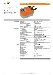
Manopola termostato (B)<br />
- Selezione della temperatura<br />
ambiente desiderata.<br />
Spia ROSSO/BLU/FUCSIA (C)<br />
- Visualizza il modo di funzionamento<br />
CALDO/FREDDO richiesto dal termostato<br />
elettronico e se l’impianto termico<br />
è in grado di soddisfare la richiesta.<br />
6<br />
-<br />
La possibilità di rimuovere la bacinella e le coclee dei<br />
ventilat<strong>or</strong>i ispezionabili (eseguibile solo da personale<br />
specializzato) consentono di eseguire una pulizia accurata<br />
anche delle parti interne, condizione necessaria per<br />
installazioni in luoghi molto affollati o che richiedono<br />
uno standard elevato di igiene.<br />
La silenziosità del nuovo gruppo di ventilazione centrifugo<br />
è tale che alla n<strong>or</strong>male velocità di utilizzo, non<br />
si percepisce quando l’FCX APC entra in funzione.<br />
L’utilizzo di pannelli di controllo elettronici evita il fastidioso<br />
rum<strong>or</strong>e tipico dei termostati meccanici.<br />
Il pannello comandi con termostato elettronico è sulla<br />
testata e consente la regolazione elettronica della temperatura,<br />
cambio di velocità manuale ed automatica sul<br />
ventilat<strong>or</strong>e, cambio di stagione automatico e accensione-spegnimento<br />
automatico.<br />
Il ventilconvett<strong>or</strong>e FCX APC è concepito per soddisfare<br />
ogni esigenza di impianto, grazie anche alla ricca dotazione<br />
di access<strong>or</strong>i.<br />
Facilità di installazione con attacchi idraulici reversibili<br />
in fase di installazione.<br />
Pieno rispetto delle n<strong>or</strong>me antin<strong>f<strong>or</strong></strong>tunistiche.<br />
La manutenzione <strong>or</strong>dinaria è ridotta alla pulizia periodica<br />
del filtro dell’aria con un aspirapolvere.<br />
+<br />
Spia GIALLA (D)<br />
- Acceso indica l’attivazione<br />
del PLASMACLUSTER e<br />
della ventilazione da parte<br />
del termostato elettronico.<br />
- Lampeggiante indica lo stato di standby<br />
o di autotest.<br />
Manopola selett<strong>or</strong>e (A)<br />
- OFF = Spento.<br />
- AUTO =Funzionamento automatico.<br />
- Selezione manuale della velocità:<br />
V1 = Velocità minima<br />
V2 = Velocità media<br />
V3 = Velocità massima
FCX APC - UTILIZZO<br />
COMANDI:<br />
Accensione<br />
Il depurat<strong>or</strong>e “PLASMACLUSTER” si attiva automaticamente quando si avvia la ventilazione.<br />
OFF Il ventilconvett<strong>or</strong>e è spento.<br />
Può però ripartire in modalità Caldo (funzione Antigelo) se la temperatura ambiente<br />
diventa inferi<strong>or</strong>e a 7°C e la temperatura dell’acqua è idonea, in questo caso il led rosso<br />
lampeggia.<br />
Per avviare il ventilconvett<strong>or</strong>e ruotare la manopola verso il modo di funzionamento desiderato<br />
in posizione AUTO o in una delle tre velocità di ventilazione.<br />
Selezione della Velocità di ventilazione<br />
AUTO Il termostato mantiene la temperatura impostata cambiando la velocità del ventilat<strong>or</strong>e in<br />
Modo Automatico, in funzione della temperatura ambiente e di quella impostata.<br />
Il termostato mantiene la temperatura impostata mediante cicli di accensione e spegnimento,<br />
utilizzando rispettivamente la velocità minima, media o massima del ventilat<strong>or</strong>e.<br />
Selezione della Temperatura<br />
Consente di impostare la temperatura desiderata.<br />
La temperatura c<strong>or</strong>rispondente al selett<strong>or</strong>e impostato nella posizione centrale, dipende<br />
dal modo di funzionamento attivo (Caldo 20°C, Freddo 25°C).<br />
Le differenze di temperatura massima e minima rispetto alla posizione centrale sono +8°C<br />
e -8°C<br />
Cambio stagione<br />
Il termostato elettronico imposta automaticamente il funzionamento a Caldo o a Freddo in funzione delle temperature dell’acqua<br />
nell’impianto. Con impostazioni particolari (programmabili solo da personale qualificato) è possibile il cambio stagione agendo<br />
sul selett<strong>or</strong>e temperatura, le visualizzazioni luminose possono variare rispetto alla configurazione standard.<br />
VISUALIZZAZIONI LUMINOSE PER L’UTENTE (FCX APC IN CONFIGURAZIONE STANDARD)<br />
Il led (C) cambia di col<strong>or</strong>e per indicare il modo di funzionamento<br />
attivo:<br />
ROSSO Acceso indica il funzionamento a Caldo<br />
(riscaldamento).<br />
Lampeggiante indica la modalità antigelo.<br />
ROSSO-FUCSIA Lampeggio alternato dei due col<strong>or</strong>i: indica il<br />
funzionamento a Caldo (riscaldamento) ma che l’acqua<br />
nell’impianto non ha anc<strong>or</strong>a raggiunto la temperatura<br />
idonea per abilitare la ventilazione.<br />
BLU Acceso indica il funzionamento a Freddo<br />
(raffreddamento).<br />
BLU-FUCSIA Lampeggio alternato dei due col<strong>or</strong>i: indica il<br />
funzionamento a Freddo (raffreddamento) ma che<br />
l’acqua nell’impianto non ha anc<strong>or</strong>a raggiunto la<br />
temperatura idonea per abilitare la ventilazione.<br />
FUCSIA Lampeggiante: ventilconvett<strong>or</strong>e in funzione Autotest.<br />
Il led (D) indica richiesta di ventilazione da parte del termostato<br />
elettronico:<br />
GIALLO Acceso: Plasmacluster in funzione e ventilazione<br />
abilitata, indica che il termostato ha rilevato<br />
una temperatura ambiente tale da richiedere<br />
l’avviamento della ventilazione, contemp<strong>or</strong>aneamente<br />
alla ventilazione viene attivato il<br />
PLASMACLUSTER.<br />
Spento: ventilazione non abilitata, indica che<br />
l’aletta è chiusa ed il ventilat<strong>or</strong>e non può partire.<br />
Se l’aletta è aperta il led (D) spento indica che il<br />
selett<strong>or</strong>e A è in posizione OFF oppure che il termostato<br />
ambiente non richiede l’avviamento.<br />
Lampeggio lento: ventilconvett<strong>or</strong>e in stand-by, la ventilazione<br />
non è abilitata perchè l’acqua circolante nell’impianto<br />
non ha anc<strong>or</strong>a raggiunto la temperatura<br />
idonea per il funzionamento.<br />
Lampeggio ciclico (n lampeggi): ventilconvett<strong>or</strong>e in<br />
funzione Autotest, il numero dei lampeggi indica il<br />
componente testato.<br />
-<br />
-<br />
-<br />
+<br />
+<br />
+<br />
7<br />
Italiano
Italiano<br />
INFORMAZIONI IMPORTANTI E MANUTENZIONE<br />
ATTENZIONE: il ventilconvett<strong>or</strong>e è collegato alla rete elettrica<br />
ed al circuito idraulico, un intervento da parte di personale non<br />
provvisto di specifica competenza tecnica può causare danni allo<br />
stesso operat<strong>or</strong>e, all’apparecchio ed all’ambiente circostante.<br />
ALIMENTARE IL VENTILCONVETTORE SOLO CON TENSIO-<br />
NE 230 VOLT MONOFASE<br />
Utilizzando alimentazioni elettriche diverse il ventilconvett<strong>or</strong>e<br />
può subire danni irreparabili.<br />
NON USARE IL VENTILCONVETTORE IN MODO IMPROPRIO<br />
Il ventilconvett<strong>or</strong>e non va utilizzato per allevare, far nascere e<br />
crescere animali.<br />
VENTILARE L'AMBIENTE<br />
Si consiglia di ventilare periodicamente l'ambiente ove è<br />
installato il ventilconvett<strong>or</strong>e, specialmente se nel locale risiedono<br />
parecchie persone o se sono presenti apparecchiature a<br />
gas o s<strong>or</strong>genti di od<strong>or</strong>i.<br />
REGOLARE CORRETTAMENTE LA TEMPERATURA<br />
La temperatura ambiente va regolata in modo da consentire il<br />
massimo benessere alle persone presenti, specialmente se si<br />
tratta di anziani, bambini o ammalati, evitando sbalzi di temperatura<br />
tra interno ed esterno superi<strong>or</strong>i a 7 °C in estate.<br />
In estate una temperatura troppo bassa comp<strong>or</strong>ta maggi<strong>or</strong>i<br />
consumi elettrici.<br />
ORIENTARE CORRETTAMENTE IL GETTO D'ARIA<br />
L'aria che esce dal ventilconvett<strong>or</strong>e non deve investire direttamente<br />
le persone; infatti, anche se a temperatura maggi<strong>or</strong>e di<br />
quella dell'ambiente, può provocare sensazione di freddo e<br />
conseguente disagio.<br />
NON USARE ACQUA TROPPO CALDA<br />
Per pulire il ventilconvett<strong>or</strong>e usare panni o spugne m<strong>or</strong>bidi<br />
bagnati in acqua al massimo a 40 °C. Non usare prodotti chimici<br />
o solventi per nessuna parte del ventilconvett<strong>or</strong>e. Non spruzzare<br />
acqua sulle superfici esterne o interne del ventilconvett<strong>or</strong>e (si<br />
potrebbero provocare dei c<strong>or</strong>ti circuiti).<br />
LIMITI DI FUNZIONAMENTO<br />
Massima temperatura ingresso acqua 80 °C<br />
Massima pressione d'esercizio 8 bar<br />
Minima temperatura media dell’acqua<br />
Per evitare fenomeni di condensazione sulla struttura esterna<br />
dell’apparecchio con ventilat<strong>or</strong>e in funzione, la temperatura<br />
media dell’acqua non deve essere inferi<strong>or</strong>e ai limiti rip<strong>or</strong>tati<br />
nella tabella sottostante, che dipendono dalle condizioni<br />
8<br />
PULIRE PERIODICAMENTE IL FILTRO<br />
Una pulizia frequente del filtro garantisce una maggi<strong>or</strong>e ef ficienza<br />
di funzionamento.<br />
Controllare se il filtro risulta molto sp<strong>or</strong>co: nel caso ripetere<br />
l’operazione più spesso.<br />
Pulire frequentemente, togliere la polvere accumulata con un<br />
aspirat<strong>or</strong>e.<br />
Quando il filtro è pulito rimontarlo sul ventilconvett<strong>or</strong>e procedendo<br />
al contrario rispetto allo smontaggio.<br />
PULIZIA STRAORDINARIA<br />
La possibilità di rimuovere le coclee dei ventilat<strong>or</strong>i ispezionabili<br />
(eseguibile solo da personale provvisto di specifica competenza<br />
tecnica) consente di eseguire una pulizia accurata delle<br />
anche delle parti interne, condizione necessaria per installazioni<br />
in luoghi molto affollati o che richiedono uno standard<br />
elevato di igiene.<br />
DURANTE IL FUNZIONAMENTO<br />
Lasciare sempre il filtro montato sul ventilconvett<strong>or</strong>e durante il<br />
funzionamento, altrimenti la polvere presente nell'aria andrà a<br />
sp<strong>or</strong>care le superfici della batteria.<br />
È NORMALE<br />
Nel funzionamento in raffreddamento può uscire del vap<strong>or</strong>e<br />
acqueo dalla mandata del ventilconvett<strong>or</strong>e.<br />
Nel funzionamento in riscaldamento un leggero fruscio d’aria<br />
può essere avvertibile in prossimità del ventilconvett<strong>or</strong>e.<br />
Talvolta il ventilconvett<strong>or</strong>e può emettere od<strong>or</strong>i sgradevoli dovuti<br />
all'accumulo di sostanze presenti nell'aria dell'ambiente (specialmente<br />
se non si provvede a ventilare periodicamente la<br />
stanza, pulire il filtro più spesso).<br />
Durante il funzionamento si potrebbero avvertire rum<strong>or</strong>i e<br />
scricchiolii interni all'apparecchio dovuti alle diverse dilatazioni<br />
termiche degli elementi (plastici e metallici), ciò comunque non<br />
indica un malfunzionamento e non provoca danni all’unità se non<br />
si supera la massima temperatura dell'acqua di ingresso.<br />
termo-igrometriche dell’aria ambiente.<br />
I suddetti limiti si riferiscono al funzionamento con ventilat<strong>or</strong>e<br />
in moto alla minima velocità.<br />
In caso di prolungata situazione con ventilat<strong>or</strong>e spento e passaggio<br />
di acqua fredda in batteria, è possibile la <strong>f<strong>or</strong></strong>mazione di<br />
condensa all’esterno dell’apparecchio, pertanto si consiglia<br />
l’inserimento dell’access<strong>or</strong>io valvola a tre vie .<br />
MINIMA TEMPERATURA MEDIA ACQUA<br />
Temperatura a bulbo secco dell’aria ambiente °C<br />
21 23 25 27 29 31<br />
15 3 3 3 3 3 3<br />
Temperatura a bulbo umido 17 3 3 3 3 3 3<br />
dell’aria ambiente °C 19 3 3 3 3 3 3<br />
21 6 5 4 3 3 3<br />
23 - 8 7 6 5 5<br />
PLASMACLUSTER<br />
Il depurat<strong>or</strong>e dell’aria Plasmacluster si attiva contemp<strong>or</strong>aneamente<br />
alla ventilazione sia a Caldo che a Freddo.<br />
Il funzionamento del dispositivo è segnalato sul pannello<br />
comandi con l’accensione del led giallo.<br />
Il sistema di depurazione Plasmacluster decompone le<br />
molecole di acqua e di ossigeno, n<strong>or</strong>malmente presenti nel-<br />
IMBALLO<br />
l’aria ambiente (“umidità” ed “ossigeno”), in ioni postivi e<br />
negativi. Tali ioni liberati nell’aria andranno ad aderire alle<br />
molecole delle sostanze inquinanti e ricombinandosi (una<br />
volta attivate) le decompongono in sottoprodotti non tossici<br />
(acqua, ossigeno ed anidride carbonica, etc..).<br />
I ventilconvett<strong>or</strong>i vengono spediti con imballo standard costituito da gusci di polistirolo espanso e cartone.
CARATTERISTICHE DI FUNZIONAMENTO<br />
I ventilconvett<strong>or</strong>i FCX APC sono <strong>f<strong>or</strong></strong>niti pronti a funzionare in configurazione<br />
standard, ma consentono all’installat<strong>or</strong>e di adeguarli<br />
alle necessità specifiche dell’impianto con access<strong>or</strong>i dedicati e<br />
personalizzando le funzioni agendo sui Dip-Switch interni (vedi<br />
IMPOSTAZIONI DIP-SWITCH).<br />
La risposta ai comandi è immediata, tranne casi particolari.<br />
Tipologie d’impianto<br />
I ventilconvett<strong>or</strong>i della serie FCX APC sono progettati per impianti<br />
a 2 tubi e configurati:<br />
- senza valvola;<br />
- con valvola a 2 vie oppure sonda acqua a valle della valvola;<br />
- con valvola a 3 vie e sonda acqua a monte della valvola.<br />
Ventilazione<br />
La ventilazione a tre velocità può essere comandata sia manualmente<br />
con selett<strong>or</strong>e in posizione V1, V2 e V3 (il termostato<br />
gestisce il ventilat<strong>or</strong>e con cicli di acceso-spento sulla velocità<br />
selezionata), oppure automaticamente con selett<strong>or</strong>e in posizione<br />
AUTO (la velocità del ventilat<strong>or</strong>e è gestita dal termostato in<br />
funzione delle condizioni ambientali).<br />
Per impianti con valvola (dip1 = ON) e installazione Sonda<br />
Acqua a monte della valvola (dip 2 = ON) è possibile un ritardo<br />
(massimo 2’40”) tra accensione valvola ed abilitazione ventilat<strong>or</strong>e<br />
(preriscaldamento scambiat<strong>or</strong>e).<br />
La ventilazione è consentita solo con l’aletta aperta, è necessario<br />
aprirle manualmente.<br />
Cambio stagione<br />
Il termostato cambia stagione automaticamente.<br />
In configurazione standard il cambio stagione avviene in base alla<br />
temperatura dell’acqua rilevata nell’impianto.<br />
In funzione delle settaggio dei Dip è possibile avere due modi<br />
di cambio stagione dal lato acqua:<br />
- Dip1 = OFF, Dip2 = OFF (configurazione standard) per il solo<br />
controllo della temperatura minima/massima;<br />
- Dip1 = ON, Dip2 = ON (configurazione con valvola a 3 vie e<br />
sonda a monte della valvola) per il controllo della temperatura<br />
minima/massima ed il preriscaldamento della batteria (ventilazione<br />
ritardata fino ad un massimo di 2’40”).<br />
Solo per impianti particolari, con sonda acqua a valle oppure<br />
valvola a 2 vie, il cambio stagione avviene dal lato aria, agendo sul<br />
selett<strong>or</strong>e di temperatura; in questo caso impostare Dip1 = ON, Dip2<br />
= OFF; questa impostazione permette di poter utilizzare il ventilconvett<strong>or</strong>e<br />
in impianti a 2 vie presistenti, ma è sconsigliata in quanto<br />
riduce la facilità d’uso del pannello comandi (la visualizzazione dello<br />
stato di funzionamento Caldo/Freddo dipende dalla temperatura selezionata<br />
e dalla temperatura dell’aria nell’ambiente).<br />
Controlli sulla temperatura dell’acqua<br />
Il termostato abilita la ventilazione solamente se la temperatura<br />
INSTALLAZIONE DELL’UNITÀ<br />
ATTENZIONE: prima di effettuare qualsiasi intervento, assicurarsi<br />
che l’alimentazione elettrica sia disinserita.<br />
ATTENZIONE: i collegamenti elettrici, l’installazione dei ventilconvett<strong>or</strong>i<br />
e dei l<strong>or</strong>o access<strong>or</strong>i devono essere eseguiti solo<br />
da soggetti in possesso dei requisiti tecnico-professionali di<br />
abilitazione all’installazione, alla tras<strong>f<strong>or</strong></strong>mazione, all’ampliamento<br />
e alla manutenzione degli impianti ed in grado di verificare<br />
gli stessi ai fini della sicurezza e della funzionalità.<br />
Il ventilconvett<strong>or</strong>e deve essere installato in posizione tale da<br />
consentire facilmente la manutenzione <strong>or</strong>dinaria (pulizia del<br />
filtro) e stra<strong>or</strong>dinaria, nonchè l’accesso alla valvola di sfiato<br />
dell’aria sulla fiancata del telaio (lato attacchi).<br />
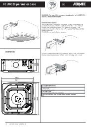
Per installare l’unità procedere come segue:<br />
- Estrarre il filtro dell’aria.<br />
- Togliere il pannello di chiusura anteri<strong>or</strong>e nel caso delle versioni<br />
pensili di grandezza da 22 a 50.<br />
- In caso di installazione a parete, si mantenga una distanza<br />
minima dal pavimento di 80 mm. In caso di installazione a<br />
pavimento per mezzo degli zoccoli, si faccia riferimento alle<br />
istruzioni a c<strong>or</strong>redo dell’access<strong>or</strong>io.<br />
- Per il fissaggio al muro o al soffitto usare dei tasselli ad espansione<br />
(non <strong>f<strong>or</strong></strong>niti) come indicato in Figg. 1 e 2.<br />
dell’acqua è idonea al modo Caldo o Freddo.<br />
Le temperature di abilitazione sia a Caldo che a Freddo sono configurabili<br />
per adattarsi alle condizioni di esecizio dell’impianto.<br />
La soglia di abilitazione a caldo è selezionabile dal Dip.5, posizione<br />
OFF per Caldo n<strong>or</strong>male (39°C) e ON per Caldo ridotto (35°C).<br />
La soglia di abilitazione a freddo è selezionabile dal Dip.6,<br />
posizione OFF per Freddo n<strong>or</strong>male (17°C) e ON per Freddo<br />
ridotto (22°C).<br />
Sul pannello comandi è segnalata la situazione in cui la temperatura<br />
dell’acqua non sia adeguata al modo di funzionamento<br />
impostato, tramite il lampeggio alternato sul led C del col<strong>or</strong>e fuxia<br />
con i col<strong>or</strong>i rosso o blu relativi al modo attivo; questa visualizzazione<br />
non è attiva con Dip1 = ON, Dip2 = OFF.<br />
Comando valvola<br />
La valvola può essere controllata in due modalità, selezionabili<br />
tramite il dip 3:<br />
- ottimizzata: sfrutta la capacità del ventilconvett<strong>or</strong>e a Caldo<br />
di erogare cal<strong>or</strong>e anche con ventilazione spenta e a Freddo di<br />
avere una ventilazione continua mantenendo il controllo della<br />
temperatura ambiente tramite la valvola;<br />
- n<strong>or</strong>male: la valvola apre o chiude in c<strong>or</strong>rispondenza dell’accensione<br />
o spegnimento del ventilat<strong>or</strong>e.<br />
C<strong>or</strong>rezione sonda<br />
É possibile selezionare il metodo di c<strong>or</strong>rezione da applicare alla<br />
sonda ambiente.<br />
Frost Protection (protezione antigelo)<br />
La protezione antigelo prevede di controllare che la temperatura<br />
ambiente non scenda mai a val<strong>or</strong>i di gelo, anche quando il ventilconvett<strong>or</strong>e<br />
è spento ed il selett<strong>or</strong>e (A) è in OFF.<br />
Nel caso in cui la temperatura scenda sotto gli 7°C il termostato avvia il<br />
ventilconvett<strong>or</strong>e nel funzionamento a caldo con set a 12°C e ventilazione<br />
in AUTO, sempre che la temperatura dell’acqua lo consenta, che il ventilconvett<strong>or</strong>e<br />
sia alimentato e che l’aletta di mandata sia in posizione aperta.<br />
Esce dal modo antigelo quando la temperatura supera i 9°C.<br />
Modo Emergenza<br />
In caso di avaria della sonda ambiente SA il termostato entra<br />
in modalità Emergenza, indicata dal lampeggiare del led (D)<br />
giallo. In questa condizione il pannello comandi si comp<strong>or</strong>ta<br />
nel modo seguente:<br />
- con selett<strong>or</strong>e (A) in posizione OFF la valvola acqua è chiusa<br />
ed il ventilat<strong>or</strong>e spento.<br />
- con selett<strong>or</strong>e (A) in posizione AUTO, V1, V2 e V3 la valvola<br />
acqua è sempre aperta ed il ventilat<strong>or</strong>e esegue dei cicli di<br />
acceso - spento; in questa situazione la potenza erogata dal<br />
terminale viene comandata maualmente tramite il selett<strong>or</strong>e (B):<br />
ruotando verso destra la durata del ciclo di Acceso aumenta;<br />
ruotando verso sinistra la durata diminuisce.<br />
- Effettuare i collegamenti idraulici.<br />
La posizione e il diametro degli attacchi idraulici sono rip<strong>or</strong>tati<br />
nei dati dimensionali. Si consiglia di isolare adeguatamente<br />
le tubazioni dell’acqua o di installare l’apposita bacinella<br />
ausiliaria di raccolta condensa, disponibile come access<strong>or</strong>io,<br />
per evitare gocciolamenti durante il funzionamento in raffreddamento.<br />
In caso di installazione <strong>or</strong>izzontale, montare il<br />
racc<strong>or</strong>do di scarico della condensa <strong>f<strong>or</strong></strong>nito a c<strong>or</strong>redo secondo<br />
quanto illustrato in figura 6. Si abbia cura di sigillare con silicone<br />
la connessione tra bacinella e racc<strong>or</strong>do. La rete di scarico<br />
della condensa deve essere opp<strong>or</strong>tunamente dimensionata e le<br />
tubazioni posizionate in modo da mantenere lungo il perc<strong>or</strong>so<br />
un’adeguata pendenza (min.1%). Nel caso di scarico nella rete<br />
fognaria, si consiglia di realizzare un sifone che impedisca la<br />
risalita di cattivi od<strong>or</strong>i verso gli ambienti.<br />
- Effettuare i collegamenti elettrici secondo quanto rip<strong>or</strong>tato<br />
negli schemi elettrici.<br />
- Rimontare l'involucro, o il pannello di chiusura anteri<strong>or</strong>e,<br />
senza dimenticarsi di connettere la sonda ambiente o il<br />
microinterrutt<strong>or</strong>e (se presenti).<br />
- Riposizionare il filtro dell’aria.<br />
9<br />
Italiano
Italiano<br />
COLLEGAMENTI ELETTRICI<br />
ATTENZIONE: prima di effettuare qualsiasi intervento, assicurarsi<br />
che l’alimentazione elettrica sia disinserita.<br />
ATTENZIONE: i collegamenti elettrici, l’installazione dei ventilconvett<strong>or</strong>i<br />
e dei l<strong>or</strong>o access<strong>or</strong>i devono essere eseguiti solo<br />
da personale specializzato.<br />
CARATTERISTICHE DEI CAVI DI COLLEGAMENTO<br />
Usare cavi tipo H05V-K oppure N07V-K con isolamento<br />
300/500 V incassati in tubo o canalina.<br />
Tutti i cavi devono essere incassati in tubo o canalina finchè<br />
non sono all’interno del ventilconvett<strong>or</strong>e.<br />
I cavi all’uscita dal tubo o canalina devono essere posizionati<br />
in modo da non subire sollecitazioni a trazione o t<strong>or</strong>sione e<br />
comunque protetti da agenti esterni.<br />
Cavi a trefolo possono essere usati solo con capic<strong>or</strong>da.<br />
Assicurarsi che i trefoli dei fili siano ben inseriti.<br />
Gli schemi elettrici sono soggetti ad un continuo aggi<strong>or</strong>namento,<br />
è obbligat<strong>or</strong>io quindi fare riferimento a quelli a b<strong>or</strong>do<br />
macchina.<br />
Per proteggere l’unità contro i c<strong>or</strong>tocircuiti, montare sulla<br />
linea di alimentazione un interrutt<strong>or</strong>e onnipolare magnetotermico<br />
2A 250V (IG) con distanza minima di apertura dei<br />
contatti di 3mm.<br />
ROTAZIONE DELLA BATTERIA<br />
Se per motivi di allacciamenti idraulici, si dovesse ruotare la<br />
batteria, dopo aver tolto il mobile o il pannello di chiusura<br />
anteri<strong>or</strong>e, procedere come segue:<br />
– togliere la vite (1) che fissa il pannello comandi (2) (se presente)<br />
alla fiancata destra ed estrarlo staccando i collegamenti<br />
elettrici;<br />
– togliere la bacinella di raccolta condensa (3);<br />
– togliere il coperchio di chiusura della batteria (4) svitando le viti;<br />
– togliere le viti che fissano la batteria (5) e quindi estrarla;<br />
– rimuovere i semitranciati e la piastrina (6) dalla fiancata<br />
destra;<br />
– ruotare la batteria (5) e fissarla con le viti precedentemente tolte;<br />
– rimontare il coperchio (4), fissandolo con le viti, e i tappi in<br />
plastica (7), <strong>f<strong>or</strong></strong>niti a c<strong>or</strong>redo, nei <strong>f<strong>or</strong></strong>i lasciati liberi dagli attac-<br />
7<br />
11<br />
10<br />
10<br />
4<br />
9<br />
Ogni pannello comandi può controllare un solo ventilconvett<strong>or</strong>e.<br />
Il luogo di montaggio deve essere scelto in modo che il limite<br />
di temperatura ambiente massimo e minimo venga rispettato<br />
0÷45°C (
CONFIGURAZIONE DIP-SWITCH<br />
* = Impostazione di fabbrica<br />
OFF<br />
ON<br />
IMPOSTAZIONI DIP-SWITCH<br />
OFF<br />
ON<br />
* Valvola di intercettazione assente<br />
* Sonda acqua a valle della valvola a tre vie o valvola a 2 vie<br />
* Gestione valvola ottimizzata<br />
* C<strong>or</strong>rezione sonda ottimizzata<br />
* Abilitazione Caldo n<strong>or</strong>male<br />
* Abilitazione Freddo n<strong>or</strong>male<br />
* Impostazione di fabbrica<br />
Plasmacluster disattivo<br />
3 4 5 6 7 8<br />
Da eseguire in fase di installazione solo da personale specializzato.<br />
Agendo sui Dip-Switch all’interno del termostato otterremo le<br />
seguenti funzionalità:<br />
(Per un c<strong>or</strong>retto funzionamento i Dip 1 e 2 devono avere la<br />
stessa impostazione).<br />
Dip 1 (Default OFF )<br />
Valvola di intercettazione:<br />
-se assente impostare OFF<br />
-se presente impostare ON<br />
Dip 2 (Default OFF )<br />
Posizione della sonda temperatura acqua:<br />
-con sonda a valle della valvola o valvola 2 vie impostare OFF,<br />
-con sonda a monte della valvola o valvola 3 vie impostare ON<br />
-la combinazione Dip.1 ON con Dip.2 OFF è sconsigliata, può<br />
trovare applicazione solo in caso di installazione su impianti<br />
che utilizzano solo 2 vie preesistenti.<br />
Dip 3 (Default OFF)<br />
Gestione valvola:<br />
-per Valvola Ottimizzata impostare OFF<br />
-per Valvola N<strong>or</strong>male impostare ON<br />
* Plasmacluster attivo<br />
É disponibile la funzione Autotest per accertare il funzionamento del ventilconvett<strong>or</strong>e,<br />
delle valvole e della resistenza.<br />
La sequenza di Autotest è la seguente:<br />
1) Selett<strong>or</strong>e (B) in posizione centrale.<br />
2) Selett<strong>or</strong>e (A) in posizione OFF.<br />
3) Agendo sul selett<strong>or</strong>e (A), eseguire velocemente la sequenza:<br />
AUTO - OFF - V1 - OFF - V2 - OFF -V3 - OFF.<br />
A questo punto si entra in modo AUTOTEST, il LED FUCSIA lampeggia.<br />
4) Con il selett<strong>or</strong>e (A) in posizione AUTO si accende la valvola.<br />
Il led giallo (D) esegue cicli di 1 lampeggio.<br />
5) Con il selett<strong>or</strong>e (A) in posizione V1 si accende la velocità minima V1.<br />
Il led giallo (D) esegue cicli di 2 lampeggi.<br />
6) Con il selett<strong>or</strong>e (A) in posizione V2 si accende la velocità media V3.<br />
Il led giallo (D) esegue cicli di 3 lampeggi.<br />
7) Con il selett<strong>or</strong>e (A) in posizione V3 si accende la velocità massima V3.<br />
Il led giallo (D) esegue cicli di 4 lampeggi .<br />
La modalità Autotest si interrompe automaticamente dopo un minuto.<br />
1 2<br />
ESEMPI DI IMPOSTAZIONE IMPIANTO<br />
Abilitazione Freddo ridotta<br />
Abilitazione Caldo ridotta<br />
C<strong>or</strong>rezione sonda fissa<br />
Gestione valvola n<strong>or</strong>male<br />
Sonda acqua a monte della valvola a tre vie<br />
Valvola di intercettazione presente<br />
Dip 4 (Default OFF)<br />
C<strong>or</strong>rezione Sonda a Caldo per compensare il surriscaldamento<br />
della strutttura metallica:<br />
-c<strong>or</strong>rezzione ottimizzata impostare OFF<br />
-c<strong>or</strong>rezzione fissa impostare ON<br />
Dip 5 (Default OFF)<br />
Abilitazione modo Caldo in base alla temperatura dell’acqua:<br />
-per modo Caldo N<strong>or</strong>male (39°C) impostare OFF<br />
-per modo Caldo Ridotto (35°C) impostare ON<br />
Dip 6 (Default OFF)<br />
Abilitazione modo Freddo in base alla temperatura dell’acqua:<br />
-per modo Freddo N<strong>or</strong>male (17°C) impostare OFF<br />
-per modo Freddo Ridotto (22°C) impostare ON<br />
Dip 7 (Default OFF)<br />
Impostazione di fabbrica OFF<br />
Dip 8 (Default ON)<br />
Abilitazione Plasmacluster:<br />
-Plasmacluster abilitato ON<br />
-Plasmacluster disabilitato OFF<br />
Dip 8 Dip 7 Dip 2 Dip 1 Tipologie d’impianto<br />
ON OFF OFF OFF Impianto 2 tubi e Plasmaculter attivo.<br />
ON OFF ON ON Impianto 2 tubi con valvola a tre vie, sonda a monte della valvola e Plasmaculter attivo.<br />
AUTOTEST<br />
B<br />
A<br />
-<br />
+<br />
11<br />
Italiano
English<br />
FCX APC - VENTILCONVETTORE FAN COILS WITH PLASMACLUSTER CON DEPURATORE AIR PURIFIER D’ARIA PLASMACLUSTER<br />
Congratulations on your purchase of <strong>the</strong> FCX APC <strong>Aermec</strong> fancoil.<br />
Made <strong>with</strong> materials of superi<strong>or</strong> quality in strict compliance <strong>with</strong> safety regulations, "FCX APC" is easy to use and<br />
will have a long life.<br />
The FCX APC fancoil combines advanced technological<br />
and operational characteristics that make it <strong>the</strong> ideal<br />
unit <strong>f<strong>or</strong></strong> air conditioning any room.<br />
The supply of climate controlled air is immediate and<br />
distributed throughout <strong>the</strong> room; FCX APC generates<br />
heat if included in heating system <strong>with</strong> boiler <strong>or</strong> heat<br />
pump but may also be used in <strong>the</strong> summer as an air conditioner<br />
if <strong>the</strong> heating system has a water chiller.<br />
The response to <strong>the</strong> commands is immediate if <strong>the</strong><br />
environmental temperature and water in <strong>the</strong> tank conditions<br />
so allows; <strong>with</strong> some special system settings, <strong>the</strong><br />
delay at which <strong>the</strong> fan comes on after <strong>the</strong> last command<br />
might be as much as 2’40”.<br />
The quality of <strong>the</strong> air treated is guaranteed by <strong>the</strong><br />
“PLASMACLUSTER” purifier that breaks down <strong>the</strong> water<br />
and oxygen molecules , n<strong>or</strong>mally present in <strong>the</strong> air in<br />
<strong>the</strong> room (“humidity” and “oxygen”), in positive and<br />
negative ions. These ions liberated into <strong>the</strong> air will stick<br />
to <strong>the</strong> molecules of <strong>the</strong> polluting substances and by<br />
being recombined (once activated) decomposes <strong>the</strong>m<br />
into non-toxic sub-products (water, oxygen and carbon<br />
dioxide etc..).<br />
The “PLASMACLUSTER” air purifier is activated at <strong>the</strong><br />
same time as <strong>the</strong> ventilation when both hot and cold.<br />
The possibility of removing <strong>the</strong> basin and <strong>the</strong> inspectionable<br />
fan volutes (only by suitably trained and qualified<br />
Thermostat knob (B)<br />
- Selection of <strong>the</strong> required<br />
room temperature.<br />
RED/BLUE/FUCHSIA Led (C)<br />
- It displays <strong>the</strong> HEATING/COOLING<br />
functioning mode required by <strong>the</strong><br />
electronic <strong>the</strong>rmostat and if <strong>the</strong> heating<br />
plant able to meet <strong>the</strong> request.<br />
12<br />
-<br />
personnel) it allows th<strong>or</strong>ough cleaning to be carried out<br />
even in <strong>the</strong> interi<strong>or</strong> parts, an essential condition when<br />
installed in very crowded areas <strong>or</strong> places requiring high<br />
standards of hygiene.<br />
The quietness of <strong>the</strong> new centrifugal fan assembly<br />
is such that at operating speed you cannot tell when<br />
<strong>the</strong> ’FCX APC cuts in, <strong>the</strong> use of <strong>the</strong> electronic control<br />
panels avoids annoying noise typical of mechanical <strong>the</strong>rmostats.<br />
The command panel <strong>with</strong> electronic <strong>the</strong>rmostat is on<br />
<strong>the</strong> head.<br />
Electronic regulation of <strong>the</strong> temperature, automatic fan<br />
speed change, automatic season change and automatic<br />
turning on and off.<br />
The FCX APC fancoil has been design to meet all<br />
system requirements partly through its extensive range of<br />
access<strong>or</strong>ies.<br />
Ease of <strong>installation</strong> that can be ei<strong>the</strong>r h<strong>or</strong>izontal <strong>or</strong><br />
<strong>vertical</strong>, <strong>with</strong> reversible plumbing attachments at <strong>the</strong><br />
<strong>installation</strong> phase.<br />
Full respect <strong>f<strong>or</strong></strong> accident prevention regulations.<br />
Routine maintenance is limited to periodic cleaning of<br />
<strong>the</strong> air filter.<br />
+<br />
YELLOW Led (D)<br />
- When on it indicates that<br />
<strong>the</strong> PLASMACLUSTER and<br />
<strong>the</strong> ventilation have been<br />
activated by <strong>the</strong> electronic <strong>the</strong>rmostat.<br />
- When flashing it indicates standby <strong>or</strong><br />
autotest status.<br />
Select<strong>or</strong> knob(A)<br />
- OFF = Off.<br />
- AUTO =Automatic operation.<br />
- Manual speed selection:<br />
V1 = Minimun fan speed<br />
V2 = Mediun fan speed<br />
V3 = Maximun fan speed
FCX APC - VENTILCONVETTORE USE<br />
CON DEPURATORE D’ARIA PLASMACLUSTER<br />
CONTROLS:<br />
The “PLASMACLUSTER” purifier cuts in automatically when <strong>the</strong> ventilation comes on.<br />
ON / OFF<br />
OFF The fancoil is off.<br />
The unit will restart in heating mode (anti-freeze function) if room temperature drops<br />
below 7°C and water temperature is suitable; in this case, <strong>the</strong> red LED lamp will flash.<br />
To restart <strong>the</strong> fancoil, rotate <strong>the</strong> knob to <strong>the</strong> operation mode required in AUTO position <strong>or</strong><br />
in one of <strong>the</strong> three fan speeds.<br />
Speed selection<br />
AUTO The <strong>the</strong>rmostat maintains <strong>the</strong> temperature of <strong>the</strong> setting by adjusting fan speed in automatic<br />
mode, acc<strong>or</strong>ding to <strong>the</strong> room temperature and <strong>the</strong> temperature setting<br />
The <strong>the</strong>rmostat maintains <strong>the</strong> temperature of <strong>the</strong> setting by on-off cycles, using minimum,<br />
medium and maximum fan speeds as required.<br />
Temperature selection<br />
Permits <strong>the</strong> required temperature to be set.<br />
The temperature c<strong>or</strong>responding <strong>with</strong> <strong>the</strong> select<strong>or</strong> set at <strong>the</strong> central position depends on<br />
<strong>the</strong> active functioning mode (Hot 20°C, Cold 25°C).<br />
The differences of minimum and maximum temperature <strong>with</strong> respect to <strong>the</strong> central position are<br />
+8°C and -8°C .<br />
Season change<br />
The electronic <strong>the</strong>rmostat automatically sets <strong>the</strong> Cold and Hot functioning acc<strong>or</strong>ding to <strong>the</strong> temperature of <strong>the</strong> water in <strong>the</strong> system.<br />
With special settings (that can only be programmed by qualified staff), <strong>the</strong> seasonal change is possible by adjusting <strong>the</strong> temperature<br />
select<strong>or</strong>, <strong>the</strong> backlit displays can vary from <strong>the</strong> standard configuration.<br />
BACKLIT DISPLAY FOR THE USER (UL PC IN THE STANDARD CONFIGURATION)<br />
The LED indicat<strong>or</strong> lamp C indicates <strong>the</strong> current operating<br />
mode:<br />
RED On indicates Heating operation<br />
(heating).<br />
Flashing indicates antifreeze mode.<br />
RED -FUCHSIA Alternate flashing of <strong>the</strong> two colours : indicates<br />
operation when hot (heating) but <strong>the</strong> water in <strong>the</strong><br />
system has not yet reached <strong>the</strong> temperature suitable<br />
<strong>f<strong>or</strong></strong> enabling <strong>the</strong> ventilation.<br />
BLUE On indicates Cooling operation<br />
(cooling).<br />
BLUE -FUCHSIA Alternate flashing of <strong>the</strong> two colours : indicates<br />
operation when cold (cooling) but <strong>the</strong> water in<br />
<strong>the</strong> system has not yet reached <strong>the</strong> temperature suitable<br />
<strong>f<strong>or</strong></strong> enabling <strong>the</strong> ventilation.<br />
FUCHSIA flashing: fan coil in autotest function.<br />
LED D: a ventilation request has been made by <strong>the</strong> electronic<br />
<strong>the</strong>rmostat:<br />
YELLOW On: Plasmacluster operating and ventilation<br />
enabled, this indicates that <strong>the</strong> <strong>the</strong>rmostat has<br />
detected a room temperature that requires <strong>the</strong><br />
ventilation to cut in, <strong>the</strong> PLASMACLUSTER is<br />
activated at <strong>the</strong> same time as <strong>the</strong> ventilation.<br />
Off: ventilation not enabled, it indicates that <strong>the</strong> louvre<br />
is closed and that <strong>the</strong> ventilat<strong>or</strong> cannot start.<br />
If <strong>the</strong> louvre is open, <strong>the</strong> led (D) off indicates that<br />
select<strong>or</strong> switch A is in <strong>the</strong> OFF position <strong>or</strong> that <strong>the</strong><br />
room <strong>the</strong>rmostat does not require start up.<br />
Slow flashing: fan coil in standby, <strong>the</strong> ventilation is not<br />
enabled because <strong>the</strong> water circulating in <strong>the</strong> plant<br />
has not yet reached <strong>the</strong> right functioning temperature.<br />
Cyclical flashing (a given no. of flashes): fan coil in<br />
Autotest function, <strong>the</strong> number of flashes indicates <strong>the</strong><br />
component tested.<br />
-<br />
-<br />
-<br />
+<br />
+<br />
+<br />
13<br />
English
English<br />
IMPORTANT MAINTENANCE INFORMATION<br />
WARNING: The fancoil is connected to <strong>the</strong> power supply and<br />
a water circuit. Operations per<strong>f<strong>or</strong></strong>med by persons <strong>with</strong>out<br />
<strong>the</strong> required technical skills can lead to personal injury to <strong>the</strong><br />
operat<strong>or</strong> <strong>or</strong> damage to <strong>the</strong> unit and surrounding objects.<br />
POWER THE FANCOIL WITH SINGLE-PHASE 230 V ONLY<br />
Use of o<strong>the</strong>r power supplies could cause permanent damage to<br />
<strong>the</strong> fancoil.<br />
NEVER USE THE FANCOIL FOR APPLICATIONS FOR WHICH<br />
IT WAS NOT DESIGNED<br />
Do not use <strong>the</strong> fancoil in husbandry applications (e.g. incubation).<br />
AIR THE ROOM<br />
Periodically air <strong>the</strong> room in which <strong>the</strong> fancoil has been installed;<br />
this is particularly imp<strong>or</strong>tant if <strong>the</strong> room is occupied by<br />
many people, <strong>or</strong> if gas appliances <strong>or</strong> sources of odours are<br />
present.<br />
CORRECTLY ADJUST THE TEMPERATURE<br />
Room temperature should be regulated to ensure maximum<br />
com<strong>f<strong>or</strong></strong>t to persons present, particularly in <strong>the</strong> case of <strong>the</strong><br />
elderly, infants and invalids. Prevent temperature fluctuations<br />
between indo<strong>or</strong>s and outdo<strong>or</strong>s greater than 7 °C during summer.<br />
Note that very low temperatures during summer will lead to<br />
greater electricity consumption.<br />
ORIENT AIR FLOW CORRECTLY<br />
Air delivered by <strong>the</strong> fancoil should not be <strong>or</strong>iented directly at<br />
people; even if air temperature is greater than room temperature,<br />
it can cause a cold sensation and consequently discom<strong>f<strong>or</strong></strong>t.<br />
DO NOT USE HOT WATER<br />
When cleaning <strong>the</strong> indo<strong>or</strong> unit, use rags <strong>or</strong> soft sponges soaked<br />
in warm water (no higher than 40°C).<br />
Do not use chemical products <strong>or</strong> solvents to clean any part of<br />
<strong>the</strong> fancoil.<br />
OPERATING LIMITS<br />
Maximum water inlet temperature 80 °C<br />
Maximum w<strong>or</strong>king pressure 8 bar<br />
Minimum average water temperature<br />
To prevent <strong>the</strong> <strong>f<strong>or</strong></strong>mation of condensation on <strong>the</strong> exteri<strong>or</strong><br />
of <strong>the</strong> unit while <strong>the</strong> fan is operating, <strong>the</strong> average water<br />
temperature should not drop beneath <strong>the</strong> limits shown in<br />
<strong>the</strong> table below, determined by <strong>the</strong> ambient conditions.<br />
14<br />
Do not splash water on interi<strong>or</strong> <strong>or</strong> exteri<strong>or</strong> surfaces of <strong>the</strong> fancoil;<br />
danger of sh<strong>or</strong>t circuit.<br />
PERIODICALLY CLEAN THE FILTER<br />
Frequent cleaning of <strong>the</strong> filter will ensure m<strong>or</strong>e efficient unit<br />
operation.<br />
Check whe<strong>the</strong>r <strong>the</strong> filter requires cleaning; if it is particularly<br />
dirty, clean it m<strong>or</strong>e often.<br />
Clean <strong>the</strong> filter frequently. Use a vacuum cleaner to remove<br />
built up dust. Avoid water <strong>or</strong> detergents if possible since <strong>the</strong>y<br />
greatly accelerate loss of <strong>the</strong> filter's electrostatic charge.<br />
After cleaning and drying <strong>the</strong> filter, fit it on <strong>the</strong> fancoil by following<br />
<strong>the</strong> removal procedure in reverse <strong>or</strong>der.<br />
SPECIAL CLEANING<br />
The removable drip tray and fan volute ensure th<strong>or</strong>ough cleaning<br />
of <strong>the</strong> unit (by specifically trained personnel), essential<br />
<strong>f<strong>or</strong></strong> <strong>installation</strong>s in venues subject to crowding <strong>or</strong> in those <strong>with</strong><br />
special hygiene requirements.<br />
DURING UNIT OPERATION<br />
Always leave <strong>the</strong> filter on <strong>the</strong> fancoil during operation (o<strong>the</strong>rwise<br />
dust in <strong>the</strong> air could soil <strong>the</strong> surface of <strong>the</strong> coil).<br />
IT IS NORMAL<br />
During cooling, water vapour may be present in <strong>the</strong> air delivery.<br />
During heating operation a light rustling sound may be perceived<br />
near <strong>the</strong> fancoil.<br />
Sometimes <strong>the</strong> fancoil can give off unpleasant odours due to<br />
<strong>the</strong> accumulation of substances present in <strong>the</strong> room: air <strong>the</strong><br />
room and clean <strong>the</strong> filter m<strong>or</strong>e often.<br />
During <strong>the</strong> operation, <strong>the</strong>re could be noises and creaks inside<br />
<strong>the</strong> device, due to <strong>the</strong> various heat expansions of <strong>the</strong> elements<br />
(plastic and metallic), but this does not indicate any malfunctioning<br />
and does not cause damage to <strong>the</strong> unit unless <strong>the</strong> maximum<br />
input water temperature is exceeded.<br />
These limits refer to unit operation <strong>with</strong> fan at minimum speed.<br />
Note that condensation may <strong>f<strong>or</strong></strong>m on <strong>the</strong> exteri<strong>or</strong> of <strong>the</strong> unit if<br />
cold water circulates through <strong>the</strong> coil while <strong>the</strong> fan is off <strong>f<strong>or</strong></strong><br />
prolonged periods of time, so it is advisable to fit <strong>the</strong> additional<br />
three-way valve.<br />
MINIMUM AVERAGE WATER TEMPERATURE<br />
Dry bulb temperature °C<br />
21 23 25 27 29 31<br />
15 3 3 3 3 3 3<br />
17 3 3 3 3 3 3<br />
Wet bulb temperature °C 19 3 3 3 3 3 3<br />
21 6 5 4 3 3 3<br />
23 - 8 7 6 5 5<br />
PLASMACLUSTER<br />
The quality of <strong>the</strong> air treated is guaranteed by <strong>the</strong><br />
“PLASMACLUSTER” purifier that breaks down <strong>the</strong> water and<br />
oxygen molecules , n<strong>or</strong>mally present in <strong>the</strong> air in <strong>the</strong> room<br />
(“humidity” and “oxygen”), in positive and negative ions.<br />
These ions liberated into <strong>the</strong> air will stick to <strong>the</strong> molecules of<br />
PACKING<br />
The units are shipped in cardboard box standard packing and polystirene shells.<br />
<strong>the</strong> polluting substances and by being recombined (once activated)<br />
decomposes <strong>the</strong>m into non-toxic sub-products (water,<br />
oxygen and carbon dioxide etc..).<br />
The “PLASMACLUSTER” air purifier is activated at <strong>the</strong> same<br />
time as <strong>the</strong> ventilation when both hot and cold.
OPERATION<br />
FCX APC fancoils are delivered ready to operate in standard<br />
configuration, though can be adjusted by <strong>the</strong> <strong>installation</strong> technician<br />
to specific requirements by means of dedicated access<strong>or</strong>ies<br />
and configuration of functions at <strong>the</strong> internal dipswitches<br />
(see DIPSWITCH CONFIGURATION).<br />
Response to controls is immediate, except in special cases.<br />
Unit types<br />
FCX APC fancoils are designed <strong>f<strong>or</strong></strong> twin-tube units, in <strong>the</strong> following<br />
types:<br />
- <strong>with</strong>out valve;<br />
- <strong>with</strong> 2-way valve (water probe below valve);<br />
- <strong>with</strong> 3-way valve (water probe above valve).<br />
Ventilation<br />
Ventilation speed can be controlled ei<strong>the</strong>r manually by setting<br />
<strong>the</strong> select<strong>or</strong> switch A to position V1, V2 <strong>or</strong> V3 (<strong>the</strong> fan operates<br />
in on-off cycles acc<strong>or</strong>ding to <strong>the</strong> speed selected), <strong>or</strong> automatically<br />
when <strong>the</strong> select<strong>or</strong> switch is set to <strong>the</strong> AUTO position (fan<br />
speed is controlled by <strong>the</strong> <strong>the</strong>rmostat acc<strong>or</strong>ding to room temperature<br />
detected).<br />
On systems <strong>with</strong> a valve (dip1 = ON) and a Water Probe installed<br />
upstream of <strong>the</strong> valve (dip2 = ON), a delay (maximum<br />
2'40'') can be set between <strong>the</strong> valve switching on and <strong>the</strong> fan<br />
starting up (pre-heating of <strong>the</strong> heat exchanger).<br />
Ventilation can only take place <strong>with</strong> <strong>the</strong> louvers open. On<br />
models where <strong>the</strong> louvers are not mot<strong>or</strong>ised <strong>the</strong>se must be<br />
opened manually.<br />
Season changeover<br />
The <strong>the</strong>rmostat changes seasonal operation automatically.<br />
Season changeover takes place acc<strong>or</strong>ding to <strong>the</strong> water temperature<br />
detected in <strong>the</strong> unit.<br />
Acc<strong>or</strong>ding to <strong>the</strong> dipswitch settings, two types of season change<br />
(water side) are possible:<br />
- Dip1 = OFF, Dip2 = OFF (standard configuration) <strong>with</strong> minimum/maximum<br />
temperature control only;<br />
- Dip1 = ON, Dip2 = ON (configuration <strong>with</strong> three-way valve<br />
and probe be<strong>f<strong>or</strong></strong>e <strong>the</strong> valve) <strong>with</strong> minimum/maximum temperature<br />
control and coil preheating (fan operation delay maximum<br />
2'40").<br />
n <strong>the</strong> case of special units <strong>with</strong> water probe below <strong>the</strong> valve <strong>or</strong> fitted<br />
<strong>with</strong> 2-way valve, season change takes place from <strong>the</strong> air side,<br />
through operation of <strong>the</strong> temperature select<strong>or</strong> switch. Though this<br />
setting allows use of <strong>the</strong> fancoil in pre-existing 2-way valve plants,<br />
it is not recommended, given that it hampers <strong>the</strong> operation of <strong>the</strong><br />
electronic <strong>the</strong>rmostat (<strong>the</strong> Heating/Cooling mode status display<br />
by LED is altered, depending on <strong>the</strong> temperature selected and <strong>the</strong><br />
room air temperature).<br />
Water temperature controls<br />
The <strong>the</strong>rmostat only enables fan operation when <strong>the</strong> water tem-<br />
UNIT INSTALLATION<br />
IMPORTANT: check that <strong>the</strong> power supply is disconnected<br />
be<strong>f<strong>or</strong></strong>e per<strong>f<strong>or</strong></strong>ming operations on <strong>the</strong> unit.<br />
CAUTION: wiring connections <strong>installation</strong> of <strong>the</strong> fancoil and<br />
relevant access<strong>or</strong>ies should be per<strong>f<strong>or</strong></strong>med by a technician<br />
who has <strong>the</strong> necessary technical and professional expertise<br />
to install, modify, extend and maintain plants and who is able<br />
to check <strong>the</strong> plants <strong>f<strong>or</strong></strong> <strong>the</strong> purposes of safety and c<strong>or</strong>rect<br />
operation.<br />
The fancoil should be installed in such a way as to facilitate<br />
routine (filter cleaning) and special maintenance operations,<br />
as well as access to <strong>the</strong> air brea<strong>the</strong>r valve on <strong>the</strong> side of <strong>the</strong><br />
unit frame (connect<strong>or</strong> side).<br />
To install <strong>the</strong> unit, proceed as follows:<br />
- Extract <strong>the</strong> air filter.<br />
- Remove <strong>the</strong> rear cover panel in <strong>the</strong> case of wall models,<br />
sizes 22 to 50.<br />
- In <strong>the</strong> case of wall-mounted, keep a minimum clearance of<br />
80 mm from <strong>the</strong> flo<strong>or</strong>. In <strong>the</strong> case of flo<strong>or</strong>-mounted units on<br />
bases, refer to <strong>the</strong> instructions supplied <strong>with</strong> <strong>the</strong> access<strong>or</strong>y.<br />
- Use expansion plugs (not supplied) to secure <strong>the</strong> unit to <strong>the</strong><br />
wall <strong>or</strong> ceiling, as shown in figures 1 and 2.<br />
perature is suitable <strong>f<strong>or</strong></strong> Heating <strong>or</strong> Cooling mode.<br />
Both <strong>the</strong> hot and cold starting up temperatures can be set to<br />
suit <strong>the</strong> conditions under which <strong>the</strong> system operates.<br />
The hot starting up threshold can be selected using Dip 5: OFF<br />
position <strong>f<strong>or</strong></strong> n<strong>or</strong>mal Heat (39°C) and ON position <strong>f<strong>or</strong></strong> reduced<br />
Heat (35°C).<br />
The cold starting up threshold can be selected using Dip 6:<br />
OFF position <strong>f<strong>or</strong></strong> n<strong>or</strong>mal Cold (17°C) and ON position <strong>f<strong>or</strong></strong> reduced<br />
Cold (22°C).<br />
If <strong>the</strong> water temperature is not suitable <strong>f<strong>or</strong></strong> <strong>the</strong> operating mode<br />
selected, LED lamp C on <strong>the</strong> control panel flashes alternately<br />
pink, red and blue next to <strong>the</strong> relative mode; this display is<br />
switched off when Dip1 = ON and Dip 2 = OFF.<br />
Valve control<br />
The valve can be controlled in two modes:<br />
- optimised: this mode exploits <strong>the</strong> capacity of <strong>the</strong> fancoil<br />
(Heating) to supply heat even when fan operation has been<br />
shut down; during Cooling, ventilation continues <strong>f<strong>or</strong></strong> control of<br />
room temperature by <strong>the</strong> valve.<br />
- n<strong>or</strong>mal: <strong>the</strong> valve opens <strong>or</strong> closes, depending on whe<strong>the</strong>r <strong>the</strong><br />
fan starts up <strong>or</strong> shuts down.<br />
Probe c<strong>or</strong>rection<br />
The required c<strong>or</strong>rection to be applied to <strong>the</strong> ambient probe can<br />
be selected.<br />
Frost Protection<br />
This function prevents room temperature from dropping below<br />
an ambient temperature of 7°C (even when <strong>the</strong> fancoil is off<br />
and select<strong>or</strong> switch A is in <strong>the</strong> OFF position).<br />
In <strong>the</strong> event that room temperature drops below 7°C, <strong>the</strong> <strong>the</strong>rmostat<br />
starts up <strong>the</strong> fancoil in heating mode at a temperature<br />
setting of 12°C and fan operation set to AUTO (if permitted by<br />
water temperature, <strong>the</strong> unit is connected to <strong>the</strong> power supply<br />
and <strong>the</strong> louvers are open, in <strong>the</strong> case of manual units).<br />
Frost protection mode is deactivated when room temperature<br />
rises above 9°C.<br />
Emergency mode<br />
In <strong>the</strong> event of failure of <strong>the</strong> SA ambient sens<strong>or</strong>, <strong>the</strong> <strong>the</strong>rmostat<br />
goes into Emergency mode as indicated by <strong>the</strong> yellow LED (D)<br />
flashing. Under <strong>the</strong>se conditions <strong>the</strong> control panel operates in<br />
<strong>the</strong> following way:<br />
- <strong>with</strong> select<strong>or</strong> switch (A) in OFF position: la valvola acqua è<br />
chiusa ed il fan off.<br />
- <strong>with</strong> select<strong>or</strong> switch (A) in AUTO, V1, V2 <strong>or</strong> V3 position: <strong>the</strong><br />
water valve remains open and <strong>the</strong> fan per<strong>f<strong>or</strong></strong>ms on-off cycles;<br />
in this case, <strong>the</strong> power supplied by <strong>the</strong> terminal is controlled<br />
manually by means of <strong>the</strong> temperature select<strong>or</strong> switch (B): rotate<br />
<strong>the</strong> switch to right to increase cycle duration, <strong>or</strong> to <strong>the</strong> left to<br />
reduce it.<br />
- Make hydraulic connections.<br />
Refer to <strong>the</strong> dimensional data <strong>f<strong>or</strong></strong> <strong>the</strong> position and diameter of<br />
<strong>the</strong> hydraulic connect<strong>or</strong>s.<br />
Insulate water lines adequately <strong>or</strong> fit <strong>the</strong> condensate drainage<br />
tray (available as an access<strong>or</strong>y) to prevent dripping during cooling<br />
applications.<br />
In case of h<strong>or</strong>izontal <strong>installation</strong>, fit <strong>the</strong> condensate discharge<br />
pipe (supplied separately) following <strong>the</strong> indications shown in<br />
picture 6. The connection between pipe and drip tray must be<br />
sealed <strong>with</strong> silicone.<br />
The condensate drainage system should be of an adequate size<br />
and be positioned to favour runoff (min. 1% slope). If condensate<br />
is discharged into <strong>the</strong> sewage system, install a siphon to<br />
prevent return of unpleasant odour into <strong>the</strong> room.<br />
- Make <strong>the</strong> electrical connections as shown in <strong>the</strong> wiring diagrams.<br />
- Remount <strong>the</strong> cover, <strong>or</strong> <strong>the</strong> front pannel, connect <strong>the</strong> ambient<br />
sens<strong>or</strong> <strong>or</strong> <strong>the</strong> microswitch (if present).<br />
- Refit <strong>the</strong> air filter.<br />
15<br />
English
English<br />
ELECTRICAL CONNECTIONS<br />
CAUTION: make sure that electrical power to <strong>the</strong> machine<br />
has been turned off be<strong>f<strong>or</strong></strong>e making electrical connections.<br />
CAUTION: wiring operations and <strong>installation</strong> of <strong>the</strong> fancoil<br />
and relative access<strong>or</strong>ies should be per<strong>f<strong>or</strong></strong>med by specialised<br />
personnel only.<br />
CONNECTION CABLE SPECIFICATIONS<br />
Use H05V-K <strong>or</strong> N07V-K type <strong>with</strong> 300/500 V insulation piped<br />
<strong>or</strong> ducted.<br />
All cables must be piped <strong>or</strong> ducted until <strong>the</strong>y are not placed<br />
inside <strong>the</strong> fan coil.<br />
The cables coming out of <strong>the</strong> pipe/duct must not be subjected<br />
to stretch <strong>or</strong> twist. They must be protected from wea<strong>the</strong>r conditions.<br />
Stranded wires may only be used in connection <strong>with</strong> terminating<br />
sleeves. It must be ensured that all individual wires are<br />
c<strong>or</strong>rectly inserted in <strong>the</strong> sleeve.<br />
All wiring diagrams are constantly updated. Please refer to <strong>the</strong><br />
ones supplied <strong>with</strong> <strong>the</strong> unit.<br />
To protect fan coils against sh<strong>or</strong>t circuits, always fit <strong>the</strong> power<br />
cable to <strong>the</strong> units <strong>with</strong> 2A 250V (IG) <strong>the</strong>rmo-magnetic all-pole<br />
switches <strong>with</strong> a minimum contact gap of 3 mm.<br />
ROTATING THE COIL<br />
If connection of utilities to <strong>the</strong> unit requires rotation of <strong>the</strong> coil, remove<br />
<strong>the</strong> cover <strong>or</strong> <strong>the</strong> front pannel, <strong>the</strong>n proceed as follows:<br />
– remove <strong>the</strong> screw (1) securing <strong>the</strong> control panel (2) (if present)<br />
to <strong>the</strong> right side of <strong>the</strong> unit, <strong>the</strong>n remove it after electrical<br />
disconnection;<br />
– remove <strong>the</strong> condensate tray (3);<br />
– remove <strong>the</strong> coil cover sheet (4) by removing <strong>the</strong> screws;<br />
– remove <strong>the</strong> screws securing <strong>the</strong> coil (5), <strong>the</strong>n remove it;<br />
– remove <strong>the</strong> push-outs and <strong>the</strong> small plate (6) on <strong>the</strong> right<br />
side;<br />
– rotate <strong>the</strong> coil (5), <strong>the</strong>n secure it in <strong>the</strong> new position <strong>with</strong> <strong>the</strong><br />
screws previously removed;<br />
– remount <strong>the</strong> coil cover sheet (4) and secure it <strong>with</strong> screws,<br />
<strong>the</strong>n insert <strong>the</strong> plastic plugs (7) supplied in <strong>the</strong> openings<br />
left free by <strong>the</strong> hydraulic connections; after removing <strong>the</strong><br />
Plasmacluster use <strong>the</strong> small plate <strong>f<strong>or</strong></strong> closing <strong>the</strong> hole on <strong>the</strong><br />
16<br />
7<br />
11<br />
10<br />
4<br />
9<br />
Each control panel can control a single fancoil.<br />
The assembling place must be chosen so that <strong>the</strong> max. and<br />
min. room temperature limit is respected 0÷45°C (
DIP-SWITCH<br />
* = Fact<strong>or</strong>y setting<br />
OFF<br />
ON<br />
OFF<br />
ON<br />
DIP-SWITCH CONFIGURATION<br />
* No shut off valve<br />
* Temperature water on exchanger <strong>or</strong> on 2-way valve<br />
* Optimised valve control<br />
* Optimised probe c<strong>or</strong>rection<br />
* Enable standard set heating<br />
* Enable standard set cooling<br />
* Werkseinstellung<br />
Plasmacluster disabled<br />
3 4 5 6 7 8<br />
Configuration of dipswitches must only be carried out by qualified<br />
personnel during unit <strong>installation</strong>.<br />
Adjust <strong>the</strong> dipswitches inside <strong>the</strong> <strong>the</strong>rmostat <strong>f<strong>or</strong></strong> <strong>the</strong> following<br />
functions:<br />
(Dip 1 and 2 must have <strong>the</strong> same configuration <strong>f<strong>or</strong></strong> a c<strong>or</strong>rect<br />
functioning).<br />
Dipswitch 1 (Default OFF )<br />
Shut-off valve:<br />
- if not fitted, set to OFF<br />
- if fitted, set to ON<br />
Dipswitch 2 (Default OFF )<br />
Water temperature probe:<br />
- if probe is below valve <strong>or</strong> 2-way valve is fitted, set to OFF<br />
- if probe is above valve <strong>or</strong> 3-way valve is fitted, set to ON<br />
Combination of Dip.1 ON <strong>with</strong> Dip.2 OFF is not recommended<br />
(used only <strong>f<strong>or</strong></strong> <strong>installation</strong> on two units using only pre-existing<br />
2-way valves).<br />
Dipswitch 3 (Default OFF)<br />
Valve control:<br />
- <strong>f<strong>or</strong></strong> Optimised valve, set to OFF<br />
- <strong>f<strong>or</strong></strong> N<strong>or</strong>mal valve, set to ON<br />
EXAMPLES OF SYSTEM SETTING<br />
* Plasmacluster enabled<br />
This function is designed to check <strong>the</strong> operation of <strong>the</strong> fan, valves and heaters.<br />
To run <strong>the</strong> Autotest function, proceed as follows:<br />
1) Select<strong>or</strong> switch B in central position.<br />
2) Select<strong>or</strong> switch A in OFF position.<br />
3) Adjust <strong>the</strong> select<strong>or</strong> switch A rapidly to obtain <strong>the</strong> following sequence:<br />
AUTO → OFF → V1 → OFF → V2 → OFF → V3 → OFF.<br />
At this stage <strong>the</strong> unit sets to AUTOTEST mode (PINK LED flashing).<br />
4) With <strong>the</strong> select<strong>or</strong> switch A in <strong>the</strong> AUTO position, <strong>the</strong> valve is activated. Yellow LED (D)<br />
runs 1-flash cycles.<br />
5) With <strong>the</strong> select<strong>or</strong> switch A in <strong>the</strong> V1 position, minimum speed V1 is activated. Yellow<br />
LED (D) runs 2-flash cycles.<br />
6) With <strong>the</strong> select<strong>or</strong> switch A in <strong>the</strong> V2 position, <strong>the</strong> medium speed V2 is activated. Yellow<br />
LED (D) runs 3-flash cycles.<br />
7) With <strong>the</strong> select<strong>or</strong> switch A in <strong>the</strong> V3 position, <strong>the</strong> maximum speed V3 is activated.<br />
Yellow LED (D) runs 4-flash cycles.<br />
The Autotest function automatically stops after one minute.<br />
1 2<br />
Dipswitch 4 (Default OFF)<br />
Probe (Heating) c<strong>or</strong>rection to compensate overheating of metal<br />
structure:<br />
- <strong>f<strong>or</strong></strong> optimised c<strong>or</strong>rection, set to OFF<br />
- <strong>f<strong>or</strong></strong> fixed c<strong>or</strong>rection, set to ON<br />
Dipswitch 5 (Default OFF)<br />
Enable Heating mode acc<strong>or</strong>ding to water temperature:<br />
- <strong>f<strong>or</strong></strong> N<strong>or</strong>mal Heating mode (39°C), set to OFF<br />
- <strong>f<strong>or</strong></strong> Reduced Heating (35°C), set to ON<br />
Dipswitch 6 (Default OFF)<br />
Enable Cooling mode acc<strong>or</strong>ding to water temperature:<br />
- <strong>f<strong>or</strong></strong> N<strong>or</strong>mal Cooling (17°C), set to OFF<br />
- <strong>f<strong>or</strong></strong> Reduced Cooling (22°C), set to ON<br />
Dip 7 (Default OFF)<br />
Fact<strong>or</strong>y settings OFF<br />
Dip 8 (Default OFF )<br />
Plasmacluster enabling:<br />
-Plasmacluster enabled ON<br />
-Plasmacluster disabled OFF<br />
Dip 8 Dip 7 Dip 2 Dip 1 System types<br />
ON OFF OFF OFF Two-pipe system and active Plasmaculter.<br />
ON OFF ON ON Two pipe system <strong>with</strong> three-way valve, upline probe and Plasmaculter active.<br />
AUTOTEST FUNKTION<br />
Enable reduced set cooling<br />
Enable reduced set heating<br />
Standard probe control<br />
Standard valve control<br />
Temperature probe be<strong>f<strong>or</strong></strong>e valve <strong>or</strong> 3-Way valve<br />
Shut off valve is present<br />
B<br />
A<br />
-<br />
+<br />
17<br />
English
Français<br />
FCX APC - VENTILO-CONVECTEUR AVEC DEPURATEUR D’AIR PLASMACLUSTER<br />
Veuillez accepter nos compliments les plus sincères pour avoir acheté le ventilo-convecteur FCX APC <strong>Aermec</strong>.<br />
Réalisé avec des matériaux de première qualité, dans le plus grand respect des n<strong>or</strong>mes de sécurité, "FCX APC" est<br />
facile à utiliser et destiné à durer longtemps.<br />
Le ventilo-convecteur FCX APC réunit des caractéristiques<br />
technologiques et fonctionnelles élevées qui en font l'appareil<br />
de climatisation idéal pour toutes les ambiance.<br />
L'émission d'air climatisé est immédiate et est distribuée<br />
dans toute la pièce; FCX APC engendre de la chaleur s'il est<br />
inséré dans un équipement <strong>the</strong>rmique avec chaudière ou<br />
pompe à chaleur mais il peut également être utilisé également<br />
pendant les mois d'été comme climatiseur si l'équipement<br />
<strong>the</strong>rmique est équipé d'un refroidisseur d'eau.<br />
La réponse aux commandes est immédiate si les conditions<br />
de température ambiante et de l'eau dans l'<strong>installation</strong> le permettent;<br />
avec certaines programmations d'<strong>installation</strong> particulières,<br />
le retard de démarrage du ventilateur après la dernière<br />
commande peut arriver jusqu'à 2’40”.<br />
La qualité de l'air traité est garantie grâce à au système de<br />
dépuration “PLASMACLUSTER” qui décompose les molécules<br />
d'eau et d'oxygène qui sont n<strong>or</strong>malement présentes dans l'air<br />
ambiant (“humidité” et “oxygène”), en ions positifs et négatifs.<br />
Ces ions libérés dans l'air adhéreront aux molécules des substances<br />
polluantes et en se recombinant (une fois activées) les<br />
décomposent en sous-produits non toxiques (eau, oxygène et<br />
anhydride carbonique, etc..).<br />
Le dépurateur de l'air“PLASMACLUSTER” s'active en même<br />
temps que la ventilation aussi bien à chaud qu'à froid.<br />
La possibilité d'enlever le bac et les vis sans fin des ventilateurs<br />
inspectionnables (opération qui ne peut être effectuée<br />
que par le personnel ayant une compétence technique spécifique)<br />
permet d'effectuer un nettoyage soigné des parties qui se<br />
trouvent à l'intérieur, condition nécessaire pour les <strong>installation</strong>s<br />
Poignée du <strong>the</strong>rmostat (B)<br />
- Sélection de la température<br />
ambiante désirée.<br />
Témoin ROUGE/BLEU/FUCHSIA (C)<br />
- Il affiche le mode de fonctionnement<br />
CHAUD/FROID demandé par le<br />
<strong>the</strong>rmostat électronique si l'<strong>installation</strong><br />
<strong>the</strong>rmique est en mesure de répondre<br />
à la demande.<br />
18<br />
-<br />
dans des lieux bondés ou qui demandent un niveau d'hygiène<br />
élevé.<br />
Le bruit émis par le nouveau groupe de ventilation centrifuge<br />
est tellement faible que l'on n'entend rien l<strong>or</strong>sque l’FCX APC<br />
entre en fonction à une vitesse n<strong>or</strong>male, l’utilisation de panneaux<br />
de contrôle électroniques évite d'entendre le pénible bruit typique<br />
des <strong>the</strong>rmostats mécaniques habituels.<br />
Le panneau de commande avec <strong>the</strong>rmostat électronique se<br />
trouve sur la tête.<br />
Réglage électronique de la température, changement de<br />
vitesse automatique sur le ventilateur, changement de saison<br />
automatique et allumage - extinction automatique.<br />
Le ventilo-convecteur FCX APC est conçu pour pouvoir<br />
répondre à toutes les exigences d'<strong>installation</strong>, grâce à tous les<br />
accessoires dont il est équipé.<br />
Facilité d'<strong>installation</strong> qui peut être aussi bien h<strong>or</strong>izontale<br />
que <strong>vertical</strong>e, avec des racc<strong>or</strong>dements hydrauliques réversibles<br />
au moment de l'<strong>installation</strong>.<br />
Con<strong>f<strong>or</strong></strong>me aux n<strong>or</strong>mes contre les accidents.<br />
La maintenance habituelle concerne uniquement le nettoyage<br />
périodique du filtre d'air.<br />
+<br />
Voyant DEL JAUNE (D)<br />
- L<strong>or</strong>squ'il est allumé, il<br />
indique l'activation du<br />
PLASMACLUSTER et de<br />
la ventilation de la part du<br />
<strong>the</strong>rmostat électronique.<br />
- L<strong>or</strong>squ'il clignote, il indique l'état de<br />
stand-by ou d'autotest.<br />
Poignée sélecteur (A)<br />
- OFF = Désactivé.<br />
- AUTO =Fonctionnement automatique.<br />
- Sélection manuelle de la vitesse:<br />
V1 = Vitesse minimale<br />
V2 = Vitesse moyenne<br />
V3 = Vitesse maximale
FCX APC - EMPLOI<br />
COMMANDES:<br />
Le dépurateur “PLASMACLUSTER” s'active automatiquement l<strong>or</strong>sque la ventilation démarre.<br />
Activation/Désactivation<br />
OFF Le ventilo-convecteur est désactivé.<br />
Toutefois il peut repartir en modalité Chaud (fonction Antigel) si la température ambiante<br />
descend au-dessous de 7°C et si la température de l'eau est appropriée; dans ce cas la Led<br />
rouge clignote.<br />
Pour démarrer le ventilo-convecteur tourner la poignée vers le mode de fonctionnement<br />
souhaité sur la position AUTO ou sur l'une des trois vitesses de ventilation.<br />
Sélecteur de la Vitesse<br />
AUTO Le <strong>the</strong>rmostat maintient la température programmée en modifiant la vitesse du ventilateur<br />
en Mode Automatique, en fonction de la température ambiante et de la température programmée.<br />
Le <strong>the</strong>rmostat maintient la température programmée avec des cycles de mise sous tension<br />
et d'extinction, en utilisant respectivement la vitesse minimale, moyenne ou maximale du<br />
ventilateur.<br />
Sélection de la température<br />
Elle permet de programmer la température souhaitée (fig. 3).<br />
La température c<strong>or</strong>respondant au sélecteur programmé dans la position centrale dépend du<br />
mode de fonctionnement actif (Chaud 20° C, Froid 25°C).<br />
Les différences de température maximale et minimale par rapp<strong>or</strong>t à la position centrale<br />
sont de +8° C et de -8° C.<br />
Changement de saison<br />
Le <strong>the</strong>rmostat électronique programme automatiquement le fonctionnement à chaud et à froid en fonction de la température<br />
de l'eau dans l'<strong>installation</strong>. Avec des programmations particulières (programmables uniquement par le personnel qualifié) il est<br />
possible de faire le changement de saison en agissant sur le sélecteur de température, les affichages lumineux peuvent varier par<br />
rapp<strong>or</strong>t aux configurations standard.<br />
AFFICHAGES LUMINEUX POUR L’UTILISATEUR(FCX APC EN CONFIGURATION STANDARD)<br />
La Led (C) change de couleur pour indiquer le mode de fonctionnement<br />
actif:<br />
ROUGE Allumé il indique le fonctionnement à Chaud<br />
(chauffage).<br />
Clignotant il indique la modalité antigel.<br />
ROUGE -FUCHSIA Clignotement alterné des deux couleurs:<br />
indique le fonctionnement à Chaud (chauffage) mais<br />
que l'eau dans l'<strong>installation</strong> n'a pas enc<strong>or</strong>e atteint la<br />
température suffisante pour habiliter la ventilation.<br />
Bleu Allumé il indique le fonctionnement à Froid<br />
(refroidissement).<br />
BLEU -FUCHSIA Clignotement alterné des deux couleurs:<br />
indique le fonctionnement à Froid (refroidissement)<br />
mais que l'eau dans l'<strong>installation</strong> n'a pas enc<strong>or</strong>e<br />
atteint la température suffisante pour habiliter la<br />
ventilation.<br />
FUCHSIA Clignotant: ventiloconvecteur en fonction d'Autotest.<br />
La Led (D) indique une requête de ventilation de la part de la<br />
part du <strong>the</strong>rmostat électronique:<br />
JAUNE Allumé: Plasmacluster en fonction et ventilation habilitée,<br />
indique que le <strong>the</strong>rmostat a relevé une température<br />
ambiante demandant le démarrage de la ventilation,<br />
le PLASMACLUSTER est activé en même temps que la<br />
ventilation.<br />
Arrêté: ventilation non habilitée, indique que<br />
l'ailette est fermée et que le ventilateur ne peut pas<br />
démarrer. Si l'ailette est ouverte, le voyant DEL (D)<br />
éteint indique que le sélecteur A est en position OFF<br />
ou bien que le <strong>the</strong>rmostat ambiant ne demande pas<br />
le démarrage.<br />
Clignotement lent: ventiloconvecteur en stand-by, la<br />
ventilation n'est pas habilitée parce quel’eau qui<br />
circule dans l'<strong>installation</strong> n'a pas enc<strong>or</strong>e atteint la<br />
température permettant le fonctionnement.<br />
Clignotement cyclique (n clignotements): ventiloconvecteur<br />
en fonction d'Autotest, le nombre de clignotements<br />
indique le composant testé.<br />
-<br />
-<br />
-<br />
+<br />
+<br />
+<br />
19<br />
Français
Français<br />
INFORMATIONS IMPORTANTES SUR LA MAINTENANCE<br />
ATTENTION: le ventilo-convecteur est connecté au réseau<br />
électrique et au circuit hydraulique : l'intervention d'un personnel<br />
sans compétence technique spécifique peut entraîner<br />
des blessures pour l'opérateur ou endommager l'appareil ou<br />
le milieu intéressé.<br />
ALIMENTER LE VENTILO-CONVECTEUR EXCLUSIVEMENT<br />
AVEC UNE TENSION DE 230 VOLTS MONOPHASE<br />
Si l'on utilise des alimentations électriques différentes, le ventilo-convecteur<br />
peut être irrémédiablement endommagé.<br />
NE PAS UTILISER LE VENTILO-CONVECTEUR DE MANIERE<br />
IMPROPRE.<br />
Le ventilo-convecteur ne doit pas être utilisé pour l'élevage, la<br />
naissance ou la croissance d'animaux.<br />
VENTILER LE LOCAL<br />
Nous conseillons de ventiler périodiquement le local où est<br />
installé le ventilo-convecteur, plus spécialement si plusieurs<br />
personnes résident dans le local ou si des appareillages à gaz<br />
ou des sources d'odeurs se trouvent dans le local.<br />
REGLER CORRECTEMENT LA TEMPERATURE<br />
La température ambiante doit être réglée de manière à permettre<br />
le bien-être maximal des personnes présentes, en particulier s'il<br />
s'agit de personnes âgées, d'enfants ou de personnes malades,<br />
en évitant des écarts de température -entre l'intérieur et l'extérieur-<br />
supérieurs à 7 °C en été. En été une température trop<br />
basse entraîne une consommation d'électricité plus imp<strong>or</strong>tante.<br />
ORIENTER CORRECTEMENT LE JET D'AIR<br />
L'air qui s<strong>or</strong>t du ventilo-convecteur ne doit pas frapper directement<br />
les personnes ; en effet, même si ce jet est à une température<br />
supérieure à celle du local, il peut provoquer une<br />
sensation de froid et donc de malaise.<br />
NE PAS UTILISER DE L'EAU TROP CHAUDE<br />
Pour nettoyer l'intérieur de l'Unité utiliser des chiffons ou des<br />
éponges souples et mouillés avec de l'eau dont la température<br />
maximale ne dépasse pas 40 °C. N'utiliser aucun produit<br />
chimique ou solvant pour nettoyer une partie quelconque du<br />
ventilo-convecteur. Ne pas asperger avec de l'eau les surfaces<br />
externes ou internes du ventilo-convecteur (on pourrait provo-<br />
LIMITES DE FONCTIONNEMENT<br />
Température maximale d'entrée de l'eau 80 °C<br />
Pression maximale de fonctionnement 8 bar<br />
Température minimale moyenne de l’eau<br />
Pour éviter les phénomènes de condensation sur la structure<br />
externe de l'appareil avec le ventilateur en service, la température<br />
moyenne de l'eau ne doit pas être inférieure aux limites<br />
reprises sur le tableau ci-après, qui dépendent des conditions<br />
<strong>the</strong>rmo-hygrométriques de l'air ambiant. Ces limites se réfèrent<br />
20<br />
quer des courts-circuits).<br />
NETTOYER LE FILTRE PERIODIQUEMENT<br />
Un nettoyage fréquent du filtre garantit une meilleure efficacité<br />
de fonctionnement.<br />
Contrôler si le filtre est sale: répéter l'opération plus souvent si<br />
nécessaire.<br />
Nettoyez fréquemment, enlevez la poussière qui s'accumule<br />
avec un aspirateur, l'utilisation d'eau et de détergent accélère<br />
sensiblement l'épuisement de la précharge électrostatique.<br />
Le remonter sur le ventilo-convecteur en adoptant la procédure<br />
inverse de celle du démontage.<br />
NETTOYAGE EXTRAORDINAIRE<br />
La possibilité d'enlever le bac et les vis sans fin des ventilateurs<br />
qui peuvent être inspectés (une opération qui doit être réalisée<br />
uniquement par un personnel doté d'une expérience technique)<br />
permettent d'effectuer un nettoyage soigné des <strong>or</strong>ganes<br />
internes également, une condition nécessaire pour une mise en<br />
place dans des locaux très fréquentés ou qui exigent un standard<br />
d'hygiène élevé.<br />
DURANT LE FONCTIONNEMENT:<br />
Laisser toujours le filtre monté sur le ventilo-convecteur durant<br />
le fonctionnement : la poussière qui se trouve dans l'air pourrait,<br />
dans le cas contraire, salir les surfaces de la batterie.<br />
IL EST NORMAL<br />
que durant la fonction de refroidissement, de la vapeur d'eau<br />
soit refoulée du ventilo-convecteur.<br />
Durant le fonctionnement pour le chauffage, une légère brise<br />
d'air peut être perçue à proximité du ventilo-convecteur.<br />
Quelquefois le ventilo-convecteur peut émettre des odeurs<br />
désagréables dues à l'accumulation de substances présentes<br />
dans l'air ambiant (plus spécialement si le local n'est pas périodiquement<br />
ventilé ; nettoyer le filtre plus souvent).<br />
Durant le fonctionnement on peut entendre des bruits et des<br />
craquements internes dus aux différentes dilatations <strong>the</strong>rmiques<br />
des éléments (en plastique ou en métal), cela n’indique<br />
pas un dysfonctionnement et ni ne provoque aucun dommage<br />
à l’unité si l’on ne dépasse pas la température maximale de<br />
l’eau en entrée.<br />
au fonctionnement avec un ventilateur en mouvement à la<br />
vitesse minimale. En cas de situation prolongée avec le ventilateur<br />
éteint et le passage de l'eau froide dans la batterie, de la<br />
buée peut se <strong>f<strong>or</strong></strong>mer à l'extérieur de l'appareil , il est conseillé<br />
d'insérer l'accessoire vanne 3 voies.<br />
TEMPÉRATURE MINIMUM MOYENNE DE L’EAU<br />
Température bulbe sèche °C<br />
21 23 25 27 29 31<br />
15 3 3 3 3 3 3<br />
17 3 3 3 3 3 3<br />
Température bulbe humide °C 19 3 3 3 3 3 3<br />
21 6 5 4 3 3 3<br />
23 - 8 7 6 5 5<br />
PLASMACLUSTER<br />
La qualité de l'air traité est garantie grâce à au système de<br />
dépuration “PLASMACLUSTER” qui décompose les molécules<br />
d'eau et d'oxygène qui sont n<strong>or</strong>malement présentes dans l'air<br />
ambiant (“humidité” et “oxygène”), en ions positifs et négatifs.<br />
Ces ions libérés dans l'air adhéreront aux molécules des sub-<br />
EMBALLAGE<br />
Les convecteurs soufflants sont expédiés dans un emballage standard<br />
composé de coques en polystyrène expansé et en carton.<br />
stances polluantes et en se recombinant (une fois activées) les<br />
décomposent en sous-produits non toxiques (eau, oxygène et<br />
anhydride carbonique, etc..).<br />
Le dépurateur de l'air“PLASMACLUSTER” s'active en même<br />
temps que la ventilation aussi bien à chaud qu'à froid.
CARACTERISTIQUES DE FONCTIONNEMENT<br />
Les ventilo-convecteurs FCX APC sont livrés prêts à fonctionner<br />
dans une configuration standard, mais ils permettent, en<br />
fait, à l'installateur de les adapter aux nécessités spécifiques de<br />
l'<strong>installation</strong> avec des accessoires dédiés, en personnalisant les<br />
fonctions et en intervenant sur les Dip-Switch internes (consulter<br />
PROGRAMMATIONS des DIP-SWITCH).<br />
La réponse aux commandes est immédiate, sauf cas particuliers.<br />
Catég<strong>or</strong>ies d'<strong>installation</strong>s<br />
Les ventilo-convecteurs de la série FCX APC sont conçus pour<br />
les <strong>installation</strong>s à 2 tubes, dans les variantes :<br />
- sans vanne;<br />
- avec vanne à 2 voies (sonde de l'eau en aval de la vanne);<br />
- avec vanne à 3 voies (sonde de l'eau en amont de la vanne).<br />
Ventilation<br />
La ventilation à trois vitesses peut être commandée soit<br />
manuellement avec le sélecteur (A) sur la position V1, V2 et V3<br />
(le ventilateur est utilisé avec des cycles activé/désactivé sur la<br />
vitesse sélectionnée), soit automatiquement avec le sélecteur<br />
sur la position AUTO (la vitesse du ventilateur est gérée par le<br />
<strong>the</strong>rmostat en fonction des conditions ambiantes).<br />
Pour les <strong>installation</strong>s avec soupape (dip1 = ON) et avec sonde eau<br />
en amont de la soupape (dip 2 = ON) il est possible de prévoir un<br />
retard (maximum 2'40") entre activation soupape et validation du<br />
ventilateur (préchauffage échangeur).<br />
La ventilation est aut<strong>or</strong>isée seulement l<strong>or</strong>sque les ailettes sont ouvertes.<br />
Changement de saison<br />
Le <strong>the</strong>rmostat change automatiquement de saison.<br />
Le changement de saison intervient sur la base de la température<br />
de l'eau relevée dans le circuit.<br />
En fonction des réglages des Dip, il est possible d'avoir deux<br />
modes de changement de saison sur le côté eau :<br />
- Dip1 = OFF, Dip2 = OFF (configuration standard) <strong>with</strong> minimum/maximum<br />
temperature control only;<br />
- Dip1 = ON, Dip2 = ON (configuration avec valves à 3 voies et<br />
sonde en amont de la valve) <strong>with</strong> minimum/maximum temperature<br />
control and coil preheating (fan operation delay maximum 2'40").<br />
Uniquement pour les <strong>installation</strong>s particulières munies d'une sonde<br />
de l'eau en aval ou d'une vanne à 2 voies, le changement de saison<br />
se fait sur le côté air en agissant sur le sélecteur de température; in<br />
questo caso impostare Dip1 = ON, Dip2 = OFF; Ce réglage permet<br />
de pouvoir utiliser le ventilo-convecteur dans des <strong>installation</strong>s<br />
préexistantes avec vanne à 2 voies. Cela est pourtant déconseillé,<br />
dans la mesure où cela réduit la facilité d'emploi du <strong>the</strong>rmostat<br />
électronique (la visualisation de l'état de fonctionnement Chauffage/<br />
Rafraîchissement au moyen de la led est faussée et dépend de la température<br />
sélectionnée et de la température de l'air ambiant).<br />
INSTALLATION DE L’UNITE<br />
ATTENTION !: avant d’effectuer une intervention quelconque<br />
s’assurer que l’alimentation électrique est bien désactivée.<br />
ATTENTION: les racc<strong>or</strong>dements électriques, l’<strong>installation</strong> des<br />
ventiloconvecteurs et de leurs accessoires ne doivent être<br />
exécutés que par des personnes en possession de la qualification<br />
technico-professionnelle requise pour l’habilitation à<br />
l’<strong>installation</strong>, la trans<strong>f<strong>or</strong></strong>mation, le développement et l’entretien<br />
des <strong>installation</strong>s, et en mesure de vérifier ces dernières<br />
aux fins de la sécurité et de la fonctionnalité.<br />
Le ventiloconvecteur doit être installé dans une position permettant<br />
d'effectuer aisément la maintenance <strong>or</strong>dinaire (nettoyage<br />
du filtre) et extra<strong>or</strong>dinaire et d'accéder à la soupape<br />
d'évent de l'air sur le côté du châssis (côté racc<strong>or</strong>ds).<br />
Pour installer l'unité, procéder comme suit :<br />
- Retirer le filtre de l'air.<br />
- Retirer le panneau de fermeture avant dans le cas des versions<br />
suspendues dans les modèles de 22 à 50.<br />
- En cas d'<strong>installation</strong> murale, maintenir une distance minimum<br />
au sol de 80 mm. En cas d'<strong>installation</strong> au sol au moyen<br />
des pieds, faire référence aux instructions accompagnant l'accessoire.<br />
- Pour la fixation au mur ou sur plafond, utiliser des chevilles à<br />
expansion (non livrées) comme indiqué sur les Fig. 1 et 2.<br />
Contrôles sur la température de l'eau<br />
Le <strong>the</strong>rmostat aut<strong>or</strong>ise la ventilation uniquement si la température<br />
de l'eau est appropriée au mode Chaud ou Froid.<br />
Les températures de validation à chaud et à froid sont configurables<br />
pour s'adapter aux conditions d'exercice de l'<strong>installation</strong>.<br />
Le seuil de validation à chaud est sélectionnable par Dip.5, position<br />
OFF pour chaud n<strong>or</strong>mal (39°C) et ON pour chaud réduit (35°C).<br />
Le seuil de validation à froid est sélectionnable par Dip.6, position<br />
OFF pour froid n<strong>or</strong>mal (17°C) et ON pour froid réduit (22°C).<br />
Le panneau de commande signale la situation où la température<br />
de l'eau n'est pas appropriée au mode de fonctionnement programmé,<br />
par le clignotement sur la led C de la couleur fuchsia<br />
avec le rouge ou le bleu relatif au mode actif; cette visualisation<br />
n'est pas active avec Dip1 = ON, Dip2 = OFF.<br />
Commande de la vanne<br />
La vanne peut être contrôlée de deux manières différentes,<br />
selezionabili tramite il dip 3:<br />
- optimisée: mode recourant à la capacité du ventilo-convecteur<br />
en Chauffage de fournir de la chaleur même si la ventilation<br />
est éteinte et, en Rafraîchissement, d'assurer une ventilation<br />
continue tout en maintenant le contrôle de la température<br />
ambiante au moyen de la vanne;<br />
- n<strong>or</strong>male: la vanne s'ouvre ou se ferme à la mise en marche<br />
ou à l'arrêt du ventilateur.<br />
Frost Protection (protection antigel)<br />
La protection antigel prévoit de contrôler que la température<br />
ambiante ne descende jamais à des valeurs de gel (même l<strong>or</strong>sque<br />
le ventilo-convecteur est éteint et que le sélecteur (A) est sur OFF).<br />
Si la température descend au-dessous de 8° C le <strong>the</strong>rmostat active<br />
le ventilo-convecteur dans le fonctionnement à chaud avec un set<br />
à 12° C et une ventilation en AUTO, à condition que la température<br />
de l'eau le permette, que le ventilo-convecteur soit alimenté<br />
et que, pour les modèles manuels avec ailettes, l'ailette de refoulement<br />
se trouve sur la position ouverte.<br />
Elle quitte le mode antigel l<strong>or</strong>sque la température dépasse les 9°C.<br />
Mode Urgence<br />
En cas d'avarie de la sonde d'ambiance SA le <strong>the</strong>rmostat passe<br />
en modalité Urgence, indiquée par le clignotement de la led<br />
(D) jaune. Dans cette condition le tableau de commande se<br />
comp<strong>or</strong>te de la façon suivante:<br />
- Le sélecteur (A) étant sur la position OFF, la vanne eau est fermée<br />
et le ventilateur est éteint.<br />
- Le sélecteur (A) étant sur la position AUTO, V1, V2 et V3, la vanne<br />
d'eau est toujours ouverte et le ventilateur exécute des cycles de marche<br />
- arrêt; dans cette situation, la puissance fournie par le terminal<br />
est commandée manuellement au moyen du sélecteur (B) : en le<br />
tournant vers la droite, la durée du cycle Marche augmente; en le<br />
tournant vers la gauche, cette durée diminue.<br />
- Effectuer les racc<strong>or</strong>dements hydrauliques.<br />
La position et le diamètre des racc<strong>or</strong>ds hydrauliques sont indiqués<br />
dans les dimensions.<br />
Il est conseillé d'isoler c<strong>or</strong>rectement les tuyauteries de l'eau<br />
ou d'installer le bac auxiliaire de récupération de la condensation,<br />
disponible comme accessoire, pour éviter les égouttements<br />
durant le fonctionnement en refroidissement.<br />
En cas d’<strong>installation</strong> h<strong>or</strong>izontale, monter le racc<strong>or</strong>d d’écoulement<br />
des condensats fourni avec l’appareil comme le montre la fig.6. Il<br />
faudra avoir soin de scéller avec du silicone le racc<strong>or</strong>dement entre<br />
le bac et le racc<strong>or</strong>d. Le réseau d’évacuation de la condensation<br />
doit être convenablement dimensionné et les tuyauteries positionnées<br />
de façon à maintenir une pente c<strong>or</strong>recte (min. 1%) le long<br />
du parcours. En cas d’évacuation dans les égouts, il est conseillé<br />
de réaliser un siphon empêchant les mauvaises odeurs de remonter<br />
dans les locaux.<br />
- Effectuer les racc<strong>or</strong>dements électriques comme indiqué sur<br />
les schémas électriques.<br />
- Remonter la carrosserie sans oublier de brancher la sonde<br />
de température ambiante ou le micro-interrupteur (s’ils sont<br />
présents).<br />
- Remettre le filtre de l’air.<br />
21<br />
Français
Français<br />
RACCORDEMENTS ELECTRIQUES<br />
ATTENTION: avant d’effectuer une quelconque intervention,<br />
s’assurer que l’alimentation électrique est coupée.<br />
ATTENTION: les racc<strong>or</strong>dements électriques, l'<strong>installation</strong> des<br />
ventiloconvecteurs et de leurs accessoires ne doivent être<br />
exécutés que par du personnel spécialisé.<br />
CARACTERISTIQUES DES CABLES DE RACCORDEMENT<br />
Utiliser des câbles du type H05V-K ou N07V-K avec isolation<br />
300/500 V en une conduite ou une goulotte.<br />
Tous les câbles doivent être insérés dans des conduites ou goulottes<br />
tant qu'ils se trouvent à l'intérieur du ventilo-convecteur.<br />
A la s<strong>or</strong>tie de la conduite ou de la goulotte, les câbles doivent<br />
être positionnés de façon à ne subir aucune sollicitation telles<br />
que tractions ou t<strong>or</strong>sions et de toutes façons ils doivent être<br />
protégés des agents atmosphériques.<br />
Les câbles tressés doivent être seulement utilisés pour des<br />
terminaux avec douilles. Il faut s’assurer que chaque fil de la<br />
tresse soit c<strong>or</strong>rectement inséré dans la douille.<br />
Nos schémas électriques étant constamment mis à jour, il faut<br />
absolument se référer à ceux fournis à b<strong>or</strong>d de nos appareils.<br />
Pour protéger l'unité contre les courts-circuits, montez<br />
sur la ligne d'alimentation un interrupteur omnipolaire<br />
magnéto<strong>the</strong>rmique 2A 250V (IG) avec une distance minimum<br />
d'ouverture des contacts de 3 mm.<br />
ROTATION DE LA BATTERIE<br />
Si pour des raisons de racc<strong>or</strong>dements hydrauliques, on doit<br />
retourner la batterie, après avoir enlevé la carrosserie ou le<br />
panneau de fermeture avant , procéder comme suit :<br />
- Enlever la vis (1) qui fixe le panneau de commande (2) (si<br />
présent) à la façade droite et le retirer en débranchant les<br />
cables électriques.<br />
- Déposer le bac des condensats (3).<br />
- Déposer le capot supérieur de la batterie (4) en enlevant les<br />
vis.<br />
- Enlever les vis de fixation de la batterie (5) et la déposer.<br />
- Enlever les pastilles prédécoupées et la plaquette (6) du coté<br />
gauche.<br />
- Retourner la batterie (5) et la fixer avec ses vis précédemment<br />
retirées.<br />
- Remonter le capot supérieur (4) avec ses vis et les bouchons<br />
en plastique (7) fournis de série dans les trous laissés libres<br />
22<br />
7<br />
11<br />
10<br />
4<br />
9<br />
Chaque panneau de commande peut contrôler un seul ventiloconvecteur.<br />
Le lieu de montage doit être choisi d’une façon que la limite de temperature<br />
ambient max. et min. soit respectée 0÷45°C (
CONFIGURATION DIP-SWITCH<br />
* = Configurations de l'usine<br />
OFF<br />
ON<br />
OFF<br />
ON<br />
PROGRAMMATION DIP-SWITCH<br />
* Vanne d'interception absenté<br />
* Sonde eau sur l'échangeur ou vanne à 2 voies<br />
* Gestion vanne optimisée<br />
* C<strong>or</strong>rection sonde optimisée<br />
* Validation chaleur n<strong>or</strong>male<br />
* Validation rafraîchissement n<strong>or</strong>mal<br />
* Configurations de l'usine<br />
Plasmacluster désactivé<br />
3 4 5 6 7 8<br />
A effectuer au cours de l'<strong>installation</strong> uniquement par un personnel<br />
spécialisé.<br />
En intervenant sur les Dip-Switch à l'intérieur du <strong>the</strong>rmostat<br />
nous obtiendrons les fonctionnalités suivantes:<br />
(Pour un fonctionnement c<strong>or</strong>rect Dip 1 et 2 doivent être dans<br />
la même position).<br />
Dip 1 (Default OFF )<br />
Vanne d'arrêt:<br />
-si absente, régler OFF<br />
-si présente, régler ON<br />
Dip 2 (Default OFF )<br />
Position de la sonde de température de l'eau:<br />
- avec une sonde en aval de la vanne ou avec une vanne à 2<br />
voies, régler OFF,<br />
- avec une sonde en amont de la vanne ou avec une vanne à 3<br />
voies, régler ON;<br />
- la combinaison Dip.1 ON avec Dip.2 OFF est déconseillée;<br />
elle ne peut être appliquée qu'en cas d'<strong>installation</strong> sur les<br />
systèmes utilisant uniquement deux voies préexistantes.<br />
Dip 3 (Default OFF)<br />
Gestion de la vanne:<br />
- pour la Vanne Optimisée, régler OFF<br />
- pour la Vanne N<strong>or</strong>male, régler ON<br />
* Plasmacluster activé<br />
La présence de la fonction d'Autotest permet de s'assurer du fonctionnement du ventiloconvecteur,<br />
des vannes et de la résistance.<br />
La séquence de l'Autotest est la suivante:<br />
1) Sélecteur (B) sur la position centrale.<br />
2) Sélecteur (A) sur la position OFF.<br />
3) A l'aide du sélecteur (A), exécuter rapidement la séquence:<br />
AUTO → OFF → V1 → OFF → V2 → OFF → V3 → OFF.<br />
A ce moment donné, on accède au mode AUTOTEST, la LED FUCHSIA clignote.<br />
4) Le sélecteur (A) étant sur la position AUTO, la vanne s'allume. La led jaune (D) exécute<br />
des cycles de 1 clignotement.<br />
5) Le sélecteur (A) étant sur la position V1, la vitesse minimale V1 est lancée. La led jaune<br />
(D) exécute des cycles de 2 clignotements.<br />
6) Le sélecteur (A) étant sur la position V2, la vitesse moyenne V2 est lancée. La led jaune<br />
(D) exécute des cycles de 3 clignotements.<br />
7) Le sélecteur (A) étant sur la position V3, la vitesse maximale V3 est lancée. La led jaune<br />
(D) exécute des cycles de 4 clignotements.<br />
La fonction Autotest s'interrompt automatiquement au bout d'une minute.<br />
1 2<br />
Dip 4 (Default OFF)<br />
C<strong>or</strong>rection de la sonde en Chauffage pour compenser la surchauffe<br />
de la structure métallique :<br />
- c<strong>or</strong>rection optimisée, régler OFF<br />
- c<strong>or</strong>rection fixe, régler ON<br />
Dip 5 (Default OFF)<br />
Validation mode Chauffage en fonction de la température de<br />
l'eau:<br />
- pour mode Chauffage N<strong>or</strong>mal (39°C), régler OFF<br />
- pour mode Chauffage Réduit (35°C), régler ON<br />
Dip 6 (Default OFF)<br />
EXEMPLES DE PROGRAMMATION DE L’INSTALLATION<br />
Validation mode Rafraîchissement en fonction de la température<br />
de l'eau :<br />
- pour mode Rafraîchissement N<strong>or</strong>mal (17°C), régler OFF<br />
- pour mode Rafraîchissement Réduit (22°C), régler ON<br />
Dip 7 (Default OFF)<br />
Configurations de l'usine OFF<br />
Dip 8 (Default ON )<br />
Habilitation Plasmacluster:<br />
-Plasmacluster habilité ON<br />
-Plasmacluster désactivé OFF<br />
Dip 8 Dip 7 Dip 2 Dip 1 Typologies d’<strong>installation</strong><br />
ON OFF OFF OFF Installation 2 tubes et Plasmaculter activé.<br />
ON OFF ON ON Installation 2 tubes avec valve à trois voies, sonde en amont de la valve et Plasmaculter activé.<br />
AUTOTEST<br />
Validation rafraîchissement réduit<br />
Validation chaleur réduit<br />
C<strong>or</strong>rection sonde fixe<br />
Gestion vanne n<strong>or</strong>male<br />
Sonda Acqua a Monte della valvola o valvola a 3 vie<br />
Présence de la vanne d'interception<br />
B<br />
A<br />
-<br />
+<br />
23<br />
Français
Deutsche<br />
FCX APC - GEBLÄSEKONVEKTOR MIT LUFTREINIGUNGSGERÄT PLASMACLUSTER<br />
Wir möchten Sie zum Kauf des Gebläsekonvekt<strong>or</strong>s FCX APC <strong>Aermec</strong> beglückwünschen.<br />
Aus Materialien von hoher Qualität und unter genauer Einhaltung der Sicherheitsbestimmungen hergestellt, lässt<br />
sich "FCX APC" einfach benutzen und wird Sie lange Zeit im Gebrauch begleiten.<br />
Der Gebläsekonvekt<strong>or</strong> FCX APC ist ein Konzentrat<br />
technologischer und funktioneller Betriebseigenschaften,<br />
die ihn zum idealen Klimagerät für jeden Raum werden<br />
lassen.<br />
Die Ausgabe klimatisierter Luft erfolgt unmittelbar<br />
und im gesamten Raum verteilt. FCX APC erzeugt auch<br />
Wärme, wenn das Gerät in eine Heizanlage mit Kessel<br />
oder Wärmepumpe eingegliedert wird, kann jedoch in<br />
den Sommermonaten auch als Klimagerät benutzt werden,<br />
wenn die Heizanlage über einen Kaltwassersatz<br />
verfügt.<br />
Die Antw<strong>or</strong>t auf die Steuerbefehle ist dann unmittelbar,<br />
sofern die Raumtemperatur und die Temperatur<br />
des in der Anlage befindlichen Wassers dies zulassen;<br />
bei einigen besonderen Anlageneinstellungen kann die<br />
Verzögerung der Inbetriebnahme des Lüfters nach dem<br />
letzten Steuerbefehl bis zu 2’40” betragen.<br />
Die Qualität der aufbereiteten Luft vom<br />
Reinigungssystem “PLASMACLUSTER” eindringen<br />
können, dass die Wasser- und Sauerstoffmoleküle in<br />
positive und negative Ionen zerlegt, die n<strong>or</strong>malerweise<br />
in der Raumluft v<strong>or</strong>handen sind ("Feuchtigkeit" und<br />
"Sauerstoff"). Diese in der Luft freigesetzten Ionen haften<br />
an den verschmutzenden Substanzen und zersetzen<br />
diese, nach ihrer erneuten Zusammensetzung (nach<br />
dem Aktivieren) in ungiftige Nebenprodukte (Wasser,<br />
Sauerstoff und Kohlendioxid, usw.).<br />
Der Luftfilter “PLASMACLUSTER” schaltet sich sowohl<br />
im Heiz- als auch Kühlbetrieb gleichzeitig mit der<br />
Lüftung ein.<br />
Thermostatgriff (B)<br />
- Auswahl der gewünschten<br />
Umgebungstemperatur.<br />
ROTE/BLAUE/FUCHSIA LED-<br />
Anzeige (C)<br />
- Zeigt die Funktionsweise WARM /<br />
KALT an, die durch das elektronische<br />
Raum<strong>the</strong>rmostat ange<strong>f<strong>or</strong></strong>dert wird, und<br />
wenn die Heizanlage in der Lage ist,<br />
dieser An<strong>f<strong>or</strong></strong>derung gerecht zu werden.<br />
24<br />
-<br />
Die Möglichkeit zum Entfernen des Beckens und der<br />
Förderschnecken der inspektionierbaren Ventilat<strong>or</strong>en<br />
(darf nur durch Personal mit technischer Fachkompetenz<br />
ausgeführt werden) gestatten eine s<strong>or</strong>gfältige Reinigung<br />
der im Inneren befindlichen Teile, was eine notwendige<br />
V<strong>or</strong>aussetzung für die Installation an Orten ist, die stark<br />
frequentiert sind oder einen hohen Hygienestandard<br />
er<strong>f<strong>or</strong></strong>dern.<br />
Die Geräuschlosigkeit des neuen Lüfteraggregats<br />
mit Zentrifuge ist derart hoch, dass bei n<strong>or</strong>maler<br />
Betriebsgeschwindigkeit nicht wahrnehmbar ist, wenn<br />
sich der FCX APC einschaltet. Die Verwendung von elektronischen<br />
Schalttafeln vermeidet den störenden Lärm,<br />
der für mechanische Thermostate typisch ist.<br />
Die Fernbedienung mit elektronischem Thermostat ist<br />
durch eine Klappe am Kopfteil geschützt.<br />
Elektronische Regelung der Temperatur, automatischer<br />
Wechsel der Geschwindigkeit des Ventilat<strong>or</strong>s, automatischer<br />
Wechsel der Jahreszeit und automatisches Ein- /<br />
Ausschalten.<br />
Der Gebläsekonvekt<strong>or</strong> FCX APC wurde bemessen, um<br />
allen An<strong>f<strong>or</strong></strong>derungen der Anlage gerecht zu werden, was<br />
ihm auch auf Grund der umfangreichen Ausstattung mit<br />
Zubehör gelingt.<br />
Einfache Installation, die sowohl h<strong>or</strong>izontal als vertikal<br />
erfolgen kann, mit in der Installationsphase vertauschbaren<br />
Wasseranschlüssen.<br />
Vollkommene Einhaltung der Unfallschutzv<strong>or</strong>schriften.<br />
Die n<strong>or</strong>male Wartung beschränkt sich auf die<br />
Reinigung des Luftfilters.<br />
+<br />
GELBE Led (D)<br />
- Das Aufleuchten der<br />
LED bedeutet, dass der<br />
PLASMACLUSTER und die<br />
Lüftung durch den elektronischen<br />
Thermostat aktiviert wurden.<br />
- Die blinkende LED steht für Standby<br />
oder Autotest.<br />
Drehschaltergriff (A)<br />
- OFF = Aus.<br />
- AUTO = Automatische Funktionsweise.<br />
- Manuelle Auswahl der Drehzahl:<br />
V1 = Mindestgeschwindigkeit<br />
V2 = Mittlere Geschwindigkeit<br />
V3 = Höchstgeschwindigkeit
FCX APC - ANWENDUNG<br />
BEDIENELEMENTE:<br />
Der Filter “PLASMACLUSTER” schaltet sich automatisch beim Start der Lüftung ein.<br />
Ein-/Abschalten der Einheit<br />
OFF Der Gebläsevekt<strong>or</strong> ist abgeschaltet<br />
Er kann im Heizbetrieb (Frostschutzfunktion) wieder anlaufen, wenn die Raumtemperatur<br />
unter 7°C abfällt und die Wassertemperatur geeignet ist; in diesem Fall blinkt die rote LED.<br />
Drehen Sie den Bedienknopf auf die gewünschte Betriebsart in Position AUTO oder auf<br />
eine der drei Ventilat<strong>or</strong>drehzahlen, um den Gebläsekonvekt<strong>or</strong> einzuschalten.<br />
Drehzahlauswahl<br />
AUTO Der Raum<strong>the</strong>rmostat hält die eingestellte Raumtemperatur aufrecht und passt die<br />
Ventilat<strong>or</strong>drehzahl automatisch der herrschenden und der v<strong>or</strong>gegebenen Raumtemperatur<br />
an.<br />
Der Raum<strong>the</strong>rmostat hält die Raumtemperatur mithilfe von Ein-/Abschaltzyklen und<br />
durch Verwendung der jeweils er<strong>f<strong>or</strong></strong>derlichen Ventilat<strong>or</strong>drehzahl (Mindest-, mittlere oder<br />
Höchstdrehzahl) aufrecht.<br />
Temperaturschalter<br />
Dieser Schalter dient zur Einstellung der gewünschten Raumtemperatur.<br />
Die Temperatur bei Mittelstellung des Wahlschalters ist von der jeweils aktiven Betriebsart<br />
abhängig (Heizen 20 °C, Kühlen 25 °C).<br />
Die Differenz der höchsten und niedrigsten Temperatur zur Mittelstellung beträgt +8 °C<br />
und -8 °C.<br />
Wechsel der Jahreszeit<br />
Der elektronische Thermostat stellt den Heiz- oder Kühlbetrieb automatisch je nach Temperatur des in der Anlage befindlichen<br />
Wassers ein. Bei besonderen Einstellungen (können nur durch Fachpersonal programmiert werden) kann der<br />
Jahreszeitenwechsel über den Temperaturwahlschalter eingestellt werden; die Leuchtanzeigen weichen in diesem Fall von denen<br />
der Standardkonfiguration ab.<br />
LEUCHTANZEIGEN FÜR DEN BENUTZER (FCX APC IN STANDARDKONFIGURATION)<br />
Die LED (C) zeigt die aktuelle Betriebsart durch Farbänderung<br />
an:<br />
ROT leuchtend zeigt die Funktionsweise Warm<br />
(Heizbetrieb) an.<br />
Blinkend zeigt die Frostschutzfunktion an.<br />
ROT-VIOLETT Abwechselndes Blinken der beiden Farben:<br />
zeigt den Heizbetrieb an, wobei das Wasser in der<br />
Anlage noch nicht die entsprechende Temperatur<br />
erreicht hat, bei der die Lüftung eingeschaltet wird.<br />
BLAU leuchtend zeigt die Funktionsweise Kalt<br />
(Kühlbetrieb) an.<br />
BLAU-VIOLETT Abwechselndes Blinken der beiden Farben:<br />
zeigt den Kühlbetrieb an, wobei das Wasser in der<br />
Anlage noch nicht die entsprechende Temperatur<br />
erreicht hat, bei der die Lüftung eingeschaltet wird.<br />
VIOLETT Blinkend: Gebläsekonvekt<strong>or</strong> funktioniert auf<br />
Autotest.<br />
Die LED (D) zeigt eine Lüftungsan<strong>f<strong>or</strong></strong>derung seitens des elektronischen<br />
Raum<strong>the</strong>rmostaten an:<br />
GELB Ein: Plasmacluster funktioniert und Lüftung ist<br />
freigegeben; dies bedeutet, dass der Thermostat eine<br />
Raumtemperatur gemessen hat, bei der die Inbetriebnahme<br />
der Lüftung notwendig ist. Gleichzeitig mit der Lüftung<br />
wird auch der PLASMACLUSTER aktiviert.<br />
Aus: Lüftung nicht freigegeben, bedeutet, dass die Klappe<br />
geschlossen ist und die Lüftung nicht starten kann.<br />
Bei geöffneter Klappe bedeutet die ausgeschaltete LED<br />
(D), dass der Wahlschalter A auf Position OFF steht<br />
bzw. dass der Raum<strong>the</strong>rmostat kein Starten der Lüftung<br />
verlangt.<br />
Langsames Blinken: Gebläsekonvekt<strong>or</strong> auf Standby, die<br />
Lüftung ist nicht freigegeben, weil das Wasser in der<br />
Anlage noch nicht die entsprechende Temperatur erreicht<br />
hat.<br />
Zyklisches Blinken (n-maliges Blinken): Gebläsekonvekt<strong>or</strong><br />
auf Autotest, je nachdem, wie oft die LED blinkt wird<br />
angezeigt, welcher Bestandteil gerade geprüft wird.<br />
-<br />
-<br />
-<br />
+<br />
+<br />
+<br />
25<br />
Deutsche
Deutsche<br />
WICHTIGE HINWEISE UND WARTUNG<br />
ACHTUNG: der Gebläsekonvekt<strong>or</strong> ist sowoul an das<br />
Stromnetz wie auch an die Wasservers<strong>or</strong>gung angeschlossen;<br />
Eingriffe durch Personen ohne spezifische technische<br />
Fachkenntnisse können zu Personenverletzungen und zu<br />
Maschinen- und Umweltschäden führen.<br />
DER GEBLÄSEKONVEKTOR DARF NUR MIT<br />
WECHSELSPANNUNG 230 VOLT BETRIEBEN WERDEN<br />
Jede andere Netzspannung kann zu nicht wiedergutzumachenden<br />
Schäden des Gebläsekonvekt<strong>or</strong>s führen.<br />
DEN GEBLÄSEKONVEKTOR NIE AUF UNZULÄSSIGE WEISE<br />
VERWENDEN<br />
Der Gebläsekonvekt<strong>or</strong> darf nicht für die Aufzucht von Tieren<br />
eingesetzt werden.<br />
RAUMBELÜFTUNG<br />
Es wird empfohlen, den Raum, in dem der Gebläsekonvekt<strong>or</strong><br />
installiert wird, regelmäßig zu lüften, ganz besonders<br />
wenn der Raum stark frequentiert wird oder Gasgeräte und<br />
Geruchsquellen v<strong>or</strong>handen sind.<br />
KORREKTE TEMPERATUREINSTELLUNG<br />
Die Raumtemperatur sollte so eingestellt werden, dass maximales<br />
Wohlbefinden der anwesenden Personen gewährleistet<br />
ist; im Sommer sollten Temperaturunterschiede von mehr als<br />
7°C zwischen Innen und Außen vermieden werden, ganz<br />
besonders für ältere Personen, Kranke und Kinder. Zu niedrige<br />
Temperaturen im Sommer führen außerdem zu einem erhöhten<br />
Energieverbrauch.<br />
KORREKTE EINSTELLUNG DES LUFTSTROMS<br />
Der vom Gebläsekonvekt<strong>or</strong> kommende Luftstrom sollte<br />
nicht direkt auf die Personen gerichtet sein; selbst wenn die<br />
Temperatur des Luftstroms höher als die des Raums ist, kann er<br />
Kälteempfinden und Unbehagen verursachen.<br />
NIE ZU WARMES WASSER BENUTZEN<br />
Das Innere der Einheit mit einem in warmem Wasser angefeuchteten<br />
(max. 40 °C) Lappen oder Schwamm reinigen. Nie<br />
chemische Produkte oder Lösemittel für die Reinigung des<br />
Gebläsekonvekt<strong>or</strong>s verwenden. Nie Wasser auf die Außenoder<br />
Innenflächen des Gerätes spritzen (Kurzschlussgefahr).<br />
GRENZWERTE FÜR DEN GERÄTEBETRIEB<br />
Maximale Wassereintrittstemperatur 80 °C<br />
Maximaler Betriebsdruck 8 bar<br />
Minimale mittlere Wassertemperatur<br />
Zur Vermeidung von Kondenswasserbildung auf der<br />
Geräteaußenseite während des Gebläsebetriebs darf die durchschnittliche<br />
Wassertemperatur nicht niedriger als die in der<br />
unten stehenden Tabelle aufgeführten Grenzwerte sein, die<br />
von den <strong>the</strong>rmohygrometrischen Raumbedingungen abhängen.<br />
26<br />
REGELMÄSSIG DEN FILTER REINIGEN<br />
Regelmäßiges Reinigendes Luftfilters gewährleistet einen dauerhaften<br />
störungsfreien Betrieb.<br />
Prüfen Sie dabei den Verschmutzungsgrad: bei starker<br />
Verschmutzung den Filter häufiger säubern.<br />
Den Filter mit einem Staubsauger und bei Bedarf mit Wasser<br />
und einem neutralen Reinigungsmittel reinigen. Nach der<br />
Reinigung und dem Trocknen des Filters den Filter wieder in<br />
den Gebläsekonvekt<strong>or</strong> einbauen und dabei in umgekehrter<br />
Reihenfolge zum Ausbau v<strong>or</strong>gehen.<br />
AUSSERGEWÖHNLICHE REINIGUNGSARBEITEN<br />
Nach Ausbau der Kondensatwanne und der inspizierbaren<br />
Ventilat<strong>or</strong>schnecken (diese Arbeiten dürfen nur von Personen<br />
mit spezifischen Fachkenntnissen ausgeführt werden) kann<br />
auch eine s<strong>or</strong>gfältige Reinigung der Innenteile des Gerätes v<strong>or</strong>genommen<br />
werden; solche Arbeiten sind für Installationen in<br />
stark frequentierten Räumen und in solchen, die einen hohen<br />
Hygienestandard er<strong>f<strong>or</strong></strong>dern, notwendig.<br />
WÄHREND DES BETRIEBS<br />
Benutzen Sie den Gebläsekonvekt<strong>or</strong> nie ohne Filter, da<br />
sonst der in der Luft schwebende Staub das Register des<br />
Wärmetauschers verschmutzt.<br />
NORMALE ERSCHEINUNG<br />
Beim Kühlbetrieb kann Wasserdampf aus dem Auslass des<br />
Gebläsekonvekt<strong>or</strong>s austreten.<br />
Beim Heizbetrieb kann ein leichtes Rauschen der Luft in der<br />
Nähe des Gebläsekonvekt<strong>or</strong>s zu vernehmen sein. Mitunter<br />
kann der Gebläsekonvekt<strong>or</strong> unangenehme Gerüche verbreiten,<br />
die durch die Anhäufung von in der Raumluft enthaltenen<br />
Stoffen verursacht werden (ganz besonders bei unzureichender<br />
Raumlüftung oder Filterreinigung).<br />
Während des Betriebs können Geräusche und Knistern<br />
im Gerät zu vernehmen sein, die auf den verschiedenen<br />
Wärmeausdehnungen der Elemente (aus Kunststoff und Metall)<br />
beruhen. Dies ist jedoch kein Anzeichen für eine Störung und<br />
bewirkt keine Schäden am Gerät, wenn die Höchsttemperatur<br />
des Wassers am Eingang nicht überschritten wird.<br />
Die genannten Grenzwerte beziehen sich auf den Gerätelauf<br />
mit Mindestdrehzahl. Bei längerem Gebläsestillstand und gleichzeitigem<br />
Kaltwasserdurchfluss durch das Register kann es auf<br />
der Geräteaußenseite zur Kondenswasserbildung kommen, als<br />
Zubehör das Dreiwege-Ventil einzubauen.<br />
MINIMALE MITTLERE WASSERTEMPERATUR<br />
Temperatur T.K. °C<br />
21 23 25 27 29 31<br />
15 3 3 3 3 3 3<br />
17 3 3 3 3 3 3<br />
Temperatur F.K. °C 19 3 3 3 3 3 3<br />
21 6 5 4 3 3 3<br />
23 - 8 7 6 5 5<br />
PLASMACLUSTER<br />
Die Qualität der aufbereiteten Luft vom Reinigungssystem<br />
“PLASMACLUSTER” eindringen können, dass die Wasser- und<br />
Sauerstoffmoleküle in positive und negative Ionen zerlegt, die<br />
n<strong>or</strong>malerweise in der Raumluft v<strong>or</strong>handen sind ("Feuchtigkeit"<br />
und "Sauerstoff"). Diese in der Luft freigesetzten Ionen haften an<br />
den verschmutzenden Substanzen und zersetzen diese, nach<br />
VERPACKUNG<br />
Die Gebläsekonvekt<strong>or</strong>en werden in einer Standard verpackung<br />
aus Polystyrol-Schutzschalen und Karton geliefert.<br />
ihrer erneuten Zusammensetzung (nach dem Aktivieren) in<br />
ungiftige Nebenprodukte (Wasser, Sauerstoff und Kohlendioxid,<br />
usw.).<br />
Der Luftfilter “PLASMACLUSTER” schaltet sich sowohl im<br />
Heiz- als auch Kühlbetrieb gleichzeitig mit der Lüftung ein.
FUNKTIONSEIGENSCHAFTEN<br />
Die Gebläsekonvekt<strong>or</strong>en FCX APC werden betriebsbereit<br />
mit Standardkonfiguration geliefert, lassen dem Installateur<br />
jedoch genügend Spielraum, um die Geräte mithilfe<br />
von Sonderzubehör spezifischen anlagentechnischen<br />
Er<strong>f<strong>or</strong></strong>dernissen anzupassen und die Funktionen mit den internen<br />
DIP - Schaltern anwenderspezifisch einzustellen (siehe<br />
EINSTELLUNG DER DIP - SCHALTER).<br />
Von einigen besonderen Fällen abgesehen sprechen die<br />
Einheiten so<strong>f<strong>or</strong></strong>t auf die Änderungen an.<br />
Anlagentypologien<br />
Die Gebläsekonvekt<strong>or</strong>en der Serie FCX APC sind für<br />
Zweileitungsanlagen mit folgenden Varianten konzipiert:<br />
- ohne Ventil;<br />
- mit Zweiwegeventil (Wassertemperaturfühler hinter dem Ventil);<br />
- Dreiwegeventil (Wassertemperaturfühler v<strong>or</strong> dem Ventil).<br />
Lüftung<br />
Die Dreistufen - Lüftung kann mit dem Wahlschalter (A) von<br />
Hand auf eine der drei Stellungen V1, V2 und V3 (das Gebläse<br />
wird abwechselnd mit der gewählten Drehzahl ein- und abgeschaltet)<br />
oder auf die Position AUTO gestellt werden (die<br />
Ventilat<strong>or</strong>drehzahl wird vom Thermostaten in Abhängigkeit von<br />
den Raumbedingungen gesteuert).<br />
In Anlagen, die mit Ventil (DIP-Schalter 1 = ON/EIN) und dem<br />
Ventil v<strong>or</strong>geschaltetem Wassertemperaturfühler (DIP-Schalter 2 =<br />
ON/EIN) ausgerüstet sind, ist eine Verzögerung (maximal 2'40")<br />
zwischen Ventileinschaltung und Ventilat<strong>or</strong>freigabe (V<strong>or</strong>wärmung<br />
des Wärmetauschers) möglich. Die Lüftung ist nur bei geöffneten<br />
Umlenkklappen freigegeben; bei den Modellen ohne mot<strong>or</strong>gesteuerte<br />
Klappen müssen die Lüftungsklappen von Hand geöffnet werden.<br />
Umschalten von Sommer- auf Winterbetrieb<br />
Der Raum<strong>the</strong>rmostat schaltet automatisch auf die saisonbedingte<br />
Betriebsart um.<br />
Das Umschalten erfolgt auf der Grundlage der in der Anlage<br />
gemessenen Wassertemperatur.<br />
In Funktion der Einstellung der DIP-Schalter sind zwei Arten<br />
der Umschaltung von Kühl-/Heizbetrieb möglich:<br />
- Dip1 = OFF, Dip2 = OFF (Standardkonfiguration) <strong>with</strong> minimum/maximum<br />
temperature control only;<br />
- Dip1 = ON, Dip2 = ON (Konfiguration mit 3-Weg-Ventil und<br />
v<strong>or</strong>geschalteter Sonde) <strong>with</strong> minimum/maximum temperature<br />
control and coil preheating (fan operation delay maximum 2'40").<br />
Nur bei speziellen Anlagen mit Wassertemperaturfühler hinter<br />
dem Ventil oder Zweiwegeventil wird die Umschaltung von Kühl-<br />
/Heizbetrieb luftseitig mit dem Temperaturschalter geschaltet; in<br />
diesem Fall Dip1 auf ON, Dip2 auf OFF stellen; diese Einstellung<br />
ermöglicht die Verwendung des Gebläsekonvekt<strong>or</strong>s in bestehenden<br />
Anlagen mit 2-wege-Ventil, wird jedoch nicht empfohlen, da<br />
sie die Bedienungsfreundlichkeit des elektronischen Reglers einschränkt<br />
(die Anzeige der Betriebsart Kühlen/Heizen mittels Led-<br />
Dioden ist abweichend, sie richtet sich nach der gewünschten<br />
Raumtemperatur sowie der effektiven Raumlufttemperatur).<br />
INSTALLATION DER EINHEIT<br />
ACHTUNG: Vergewissern Sie sich, dass die Stromvers<strong>or</strong>gung<br />
des Gerätes unterbrochen ist, bev<strong>or</strong> Sie Eingriffe an demselben<br />
v<strong>or</strong>nehmen.<br />
ACHTUNG: Der Stromanschluß sowie die Installation der<br />
Gebläsekonvekt<strong>or</strong>en und deren Zubehörteile darf nur von<br />
qualifizertem Fachpersonal durchgeführt werden, das die<br />
technisch-professionellen Fähigkeiten für die Installation, den<br />
Umbau, die Erweiterung und die Wartung von Anlagen besitzt<br />
und fähig ist, solche Anlagen auf Sicherheitsan<strong>f<strong>or</strong></strong>derungen<br />
und Funktionstüchtigkeit zu überprüfen.<br />
Der Einbau des Gebläsekonvekt<strong>or</strong>s soll die regelmäßige<br />
(Filterreinigung) und außerplanmäßige Wartung sowie den<br />
Zugriff des Entlüftungsventils auf Rahmenseite (Anschlußseite)<br />
problemlos gestatten.<br />
Die Einheit wird folgendermaßen installiert:<br />
- Luftfilter ausziehen.<br />
- Gehäuse bzw. v<strong>or</strong>dere Abdeckung in Deckenmodellen<br />
Größe 22 bis 50 durch Losdrehen der Schrauben abnehmen.<br />
- Bei Wand<strong>installation</strong> ist eine Bodenhöhe von mindestens 80<br />
mm v<strong>or</strong>geschrieben. Für Boden<strong>installation</strong>en auf Sockel wird<br />
auf die beiliegenden Zubehöranleitungen verwiesen.<br />
Kontrolle der Wassertemperatur<br />
Der Raum<strong>the</strong>rmostat gibt die Lüftung nur frei, wenn die Wassertemperatur<br />
den V<strong>or</strong>gaben für Heiz- oder Kühlbetrieb entsprechen.<br />
Die Einschalttemperaturen des Warm- oder Kaltwasserbetriebs<br />
sind einstellbar und können den spezifischen<br />
Anlagenbedingungen angepasst werden.<br />
Die Ansprechschwelle beim Warmwasserbetrieb ist mit DIP-<br />
Schalter 5 auswählbar: Stellung OFF/ AUS für N<strong>or</strong>malwärme<br />
(39°C) und ON/EIN für reduzierte Wärme (35°C).<br />
Die Ansprechschwelle bei Kaltwasserbetrieb ist mit DIP-Schalter<br />
6 auswählbar: Stellung OFF/AUS für N<strong>or</strong>malkühlung (17°C) und<br />
ON/EIN für reduzierte Kühlung (22°C).<br />
Auf dem Bedienteil wird durch abwechselndes Blinken der<br />
fuchsiafarbenen Led C in den Farben Rot und Blau (je nach<br />
aktiver Betriebsart) angezeigt, wenn die Wassertemperatur<br />
nicht zur gewünschten Betriebsart passt; diese Anzeige ist bei<br />
DIP-Schalter Dip1 = ON, Dip2 = OFF nicht aktiv.<br />
Ventilsteuerung<br />
Das Ventil kann auf zwei Arten angesteuert werden, die<br />
Einstellung erfolgt über Dip 1:<br />
- Optimierter Betrieb: Hierbei wird die Fähigkeit des<br />
Gebläsekonvekt<strong>or</strong>s genutzt, in heißem Zustand auch bei ausgeschaltetem<br />
Gebläse Wärme abgeben zu können, und in kaltem<br />
Zustand durch Regelung der Raumtemperatur über das Ventil<br />
eine kontinuierliche Lüftung aufrechtzuerhalten.<br />
- N<strong>or</strong>malbetrieb: Das Ventil öffnet bzw. schließt bei Ein- und<br />
Ausschaltung des Gebläses.<br />
Fühlerk<strong>or</strong>rektur<br />
Möglichkeit zur Auswahl der anzuwendende Fühlerk<strong>or</strong>rektur.<br />
Frost Protection (Frostschutz)<br />
Der Frostschutz überwacht, dass die Raumtemperatur nie<br />
unter den Grenzwert absinkt (auch bei ausgeschaltetem<br />
Gebläsevekt<strong>or</strong> und bei Wahlschalter (A) in Stellung OFF).<br />
Sobald die Temperatur unter 7°C abfällt, lässt der Thermostat den<br />
Gebläsevekt<strong>or</strong> im Heizbetrieb mit Sollwert 12°C und automatischer<br />
Lüftung (AUTO) anlaufen, v<strong>or</strong>ausgesetzt, die Wassertemperatur<br />
lässt es zu, der Gebläsevekt<strong>or</strong> steht unter Spannung und die<br />
Umlenkklappe der Modelle ohne Mot<strong>or</strong>steuerung ist geöffnet.<br />
Das Gerät schaltet ab, sobald die Temperatur über 9°C ansteigt.<br />
Notbetrieb<br />
Bei einer Störung der Raumtemperatursonde SA zeigt der<br />
Thermostat durch Blinken der gelben LED (D) einen Alarm an. In<br />
diesem Fall verhält sich die Bedienungstafel, wie folgt:<br />
- Bei Wahlschalter (A) auf OFF sind das Wassermengenventil<br />
geschlossen und das Gebläse ausgeschaltet.<br />
- Bei Wahlschalter (A) in Stellung AUTO, V1, V2 oder V3<br />
ist das Wassermengenventil geöffnet und das Gebläse führt<br />
zyklische Ein-/Ausschaltungen durch. In diesem Fall wird die<br />
Leistungsabgabe des Innengeräts von Hand über Wahlschalter<br />
(B) geregelt. Drehen nach rechts verlängert die Dauer der<br />
Einschaltung, Drehen nach links verkürzt sie.<br />
- Zur Wand- und Deckenbefestigung mit (nicht beigestellten)<br />
Dübeln gemäß Abb. 1, 2 v<strong>or</strong>gehen.<br />
- Wasseranschlüsse v<strong>or</strong>nehmen.<br />
Lage und Durchmesser der Wasseranschlüsse, vgl. Abmessungen<br />
Wasserleitungen entsprechend isolieren bzw. zusätzliche<br />
Kondensatwanne (Sonderzubehör) zum Tropfschutz im<br />
Kühlbetrieb installieren.<br />
Bei h<strong>or</strong>izontaler Installation, die separatmitgelieferte<br />
Verschraubung für den Kondensatablass wie nach Abb. 6 montieren.<br />
Bitte die Verbindung Kondensatwanne - Verschraubung<br />
mit Silicon versiegeln. Das Kondensatablaßnetz muß genau<br />
bemessen und die Leitungen so verlegt werden, daß während<br />
des gesamten Verlaufs eine ausreichende Neigung (min.<br />
1%) v<strong>or</strong>handen ist. Bei Ablaß in das Abwassernetz wird die<br />
Ausführung eines Siphons empfohlen, der das Hochsteigen<br />
unangenehmer Gerüche in die Räume vermeidet.<br />
- Die Stromanschlüsse wie in den Schaltplänen dargestellt ausführen.<br />
- Die Verkleidung wieder anbringen, den Raumfühler oder den<br />
Mikroschalter (falls v<strong>or</strong>handen) anschließen.<br />
- Den Luftfilter wieder einsetzen.<br />
27<br />
Deutsche
Deutsche<br />
ELEKTRISCHE ANSCHLÜSSE<br />
ACHTUNG: v<strong>or</strong> dem Beginn der Arbeiten überprüfen, ob die<br />
Stromvers<strong>or</strong>gung abgeschaltet ist.<br />
ACHTUNG: der Stromanschluss sowie die Installation der<br />
Gebläsekonvekt<strong>or</strong>en und deren Zubehörteile darf nur von<br />
qualifiziertem Fachpersonal durchgeführt werden.<br />
MERKMALE DER ANSCHLUSSKABEL<br />
Bei Verlegung im Rohr oder im Kanal Kabel vom Typ H05V-K<br />
oder N07V-K mit Isolierung 300/500 V verwenden.<br />
Alle Kabel bis zum Gebläsenkonvekt<strong>or</strong> müßen im Rohr oder<br />
im Kanal eingelassen sein.<br />
Die Kabel, die vom Rohr oder vom Kanal ausgehen, müßen<br />
unter keine Zugkraft oder Drehung untergestellt sein und auf<br />
jeden Fall müßen sie gegen Witterungseinflüsse geschützt sein.<br />
Litzen dürfen nur in Verbindung mit Aderendhülsen<br />
verwendet werden. Dabei ist sicherzustellen, dass sich alle<br />
Litzendrähte sauber in der Hülse befinden.<br />
Die Schaltpläne werden ständig aktualisiert, deswegen muss<br />
man sich stets auf das mit dem Gerät gelieferte Schaltschema<br />
beziehen.<br />
Um die Einheit v<strong>or</strong> Kurzschlüssen zu schützen, ist ein allpoliger<br />
FI-Schalter 2A 250V (IG) mit einem Mindestabstand der<br />
Kontaktöffnung von 3mm in der Netzleitung zu montieren.<br />
IDREHEN DER BATTERIE<br />
Ist bedingt durch die An<strong>or</strong>dnung der Wasseranschlüsse die<br />
Drehung der Batterie er<strong>f<strong>or</strong></strong>derlich, ist nach Wegnahme der<br />
Verkleidung wie folgt zu verfahren:<br />
– Die Schraube lösen (1), die das Schaltfeld (2) (falls v<strong>or</strong>gesehen)<br />
an der rechten Seite befestigt und es durch Trennen<br />
der elektrischen Anschlüsse herausziehen;<br />
– das Schutzblech der Batterie und, falls v<strong>or</strong>handen, die<br />
Kondensatauffangschale abnehmen (3);<br />
– das Batterieverschlußblech (4) durch Lösen der Schrauben<br />
abnehmen;<br />
– die Befestigungsschrauben (5) der Batterie lösen und sie<br />
herausnehmen;<br />
– - die V<strong>or</strong>stanzungen und das viereckige Abdeckblech (6) von<br />
der rechten Seite abnehmen;<br />
– die Batterie (5) drehen und mit den zuv<strong>or</strong> abgenommenen<br />
Schrauben befestigen;<br />
– das Verschlußblech (4) wieder anbringen und mit den<br />
Schrauben befestigen, die mitgelieferten Plastikstöpsel (7)<br />
in die freigew<strong>or</strong>denen Öffnungen einsetzen; das viereckige<br />
28<br />
7<br />
11<br />
10<br />
4<br />
9<br />
Jedes Bedienfeld dient zur Steuerung nur eines<br />
Gebläsekonvekt<strong>or</strong>s.<br />
Der Montage-Ort muss so gewählt sein, dass die obere<br />
Arbeitstemperatur-Grenze nicht überschritten und die unterer<br />
Arbeitstemperatur-Grenze nicht unterschritten wird 0÷45°C<br />
(
KONFIGURATION<br />
* = Werkseinstellung<br />
EINSTELLUNG DES DIP-SCHALTERS<br />
Diese Einstellung muss bei der Installation von einer Fachkraft<br />
v<strong>or</strong>genommen werden.<br />
Mit den DIP-Schaltern im Temperaturregler werden folgende<br />
Funktionen aktiviert:<br />
(Für einen n<strong>or</strong>malen Betrieb sollen Dip 1 - 2 dieselbe<br />
Einstellung haben).<br />
Dip-Schalter 1 (V<strong>or</strong>einstellung OFF )<br />
Absperrventil:<br />
- falls nicht montiert, auf OFF schalten<br />
- falls montiert, auf ON schalten<br />
Dip-Schalter 2 (V<strong>or</strong>einstellung OFF )<br />
Position des Wassertemperaturfühlers:<br />
- Temperaturfühler hinter dem Ventil oder Zweiwegeventil - auf<br />
OFF schalten,<br />
- Temperaturfühler v<strong>or</strong> dem Ventil oder Dreiwegeventil - auf<br />
ON schalten.<br />
- Die Kombination Dip-Schalter 1 auf ON und Dip-Schalter<br />
2 auf OFF ist nicht empfehlenswert. Sie wird nur bei<br />
Installationen in bestehende Anlagen mit nur 2 Leitungen<br />
verwendet.<br />
Dip-Schalter 3 (V<strong>or</strong>einstellung OFF)<br />
Ventilsteuerung:<br />
- Ventil mit optimiertem Betrieb: auf OFF schalten<br />
- Ventil mit N<strong>or</strong>malbetrieb: auf ON schalten<br />
BEISPIELE FÜR ANLAGENEINSTELLUNGEN<br />
Die Autotest-Funktion muss ausgeführt werden, um den einwandfreien Betrieb des<br />
Gebläses sowie der Ventile und des Heizelements nachzuweisen.<br />
Der Ablauf der Autotest-Funktion ist wie folgt:<br />
1) Wahlschalter (B) in Mittelstellung.<br />
2) Wahlschalter (A) in Stellung OFF.<br />
3) Mit Wahlschalter (A) rasch die folgende Sequenz schalten:<br />
AUTO → OFF → V1 → OFF → V2 → OFF → V3 → OFF.<br />
Hiermit wird der AUTOTEST-Modus eingeschaltet, die FUCHSIAFARBENE LED blinkt.<br />
4) Mit Wahlschalter (A) in Stellung AUTO das Ventil einschalten. Die gelbe Led (D) blinkt<br />
zyklisch jeweils einmal.<br />
5) Mit Wahlschalter (A) in Stellung V1 die Mindestdrehzahl V1 einschalten. Die gelbe Led<br />
(D) blinkt zyklisch jeweils zweimal.<br />
6) Mit Wahlschalter (A) in Stellung V2 die mittlere Drehzahlstufe V2 einschalten. Die gelbe<br />
Led (D) blinkt zyklisch jeweils dreimal.<br />
7) Mit Wahlschalter (A) in Stellung V3 die Höchstdrehzahl V3 einschalten. Die gelbe Led<br />
(D) blinkt zyklisch jeweils viermal.<br />
Der Autotest-Modus bricht automatisch nach einer Minute ab.<br />
Dip-Schalter 4 (V<strong>or</strong>einstellung OFF)<br />
Bei Heizbetrieb K<strong>or</strong>rektur des Temperaturfühlers zur<br />
Kompensation der Wärmeausdehnung des Metallgehäuses:<br />
- Optimierte K<strong>or</strong>rektur: auf OFF schalten<br />
- K<strong>or</strong>rektur mit Festwert: auf ON schalten<br />
Dip-Schalter 5 (V<strong>or</strong>einstellung OFF)<br />
Freigabe des Heizbetriebs in Funktion der Wassertemperatur:<br />
- für n<strong>or</strong>malen Heizbetrieb (39 °C) auf OFF schalten<br />
- für reduzierten Heizbetrieb (35 °C) auf ON schalten<br />
Dip-Schalter 6 (V<strong>or</strong>einstellung OFF)<br />
Freigabe des Kühlbetriebs in Funktion der Wassertemperatur:<br />
- für n<strong>or</strong>malen Kühlbetrieb (17 °C) auf OFF schalten<br />
- für reduzierten Kühlbetrieb (22 °C) auf ON schalten.<br />
Dip 7 (Default OFF)<br />
Werkseinstellung OFF<br />
Dip 8 (Default ON)<br />
Einschalten des Plasmacluster:<br />
-Plasmacluster ein ON<br />
-Plasmacluster aus OFF<br />
Dip 8 Dip 7 Dip 2 Dip 1 Anlagentypen<br />
ON OFF OFF OFF 2-Leiter-System und Plasmacluster ein.<br />
ON OFF ON ON 2-Leiter-System mit 3-Weg-Ventil, v<strong>or</strong>geschaltetem Ventil und Plasmacluster ein.<br />
AUTOTEST-FUNKTION<br />
OFF<br />
ON<br />
OFF<br />
ON<br />
* Sonde eau sur l'échangeur ou vanne à 2 voies<br />
* Wasserfühler auf Wärmetauscher oder 2-Wege Ventil<br />
* Optimaler Ventilkontrolle<br />
* N<strong>or</strong>maler Heizbetrieb<br />
* N<strong>or</strong>maler Heizbetrieb<br />
* N<strong>or</strong>maler Kühlbetrieb<br />
* Werkseinstellung<br />
Plasmacluster aus<br />
1 2<br />
3 4 5 6 7 8<br />
* Plasmacluster ein<br />
Reduzierter Kèhlbetrieb<br />
Reduzierter Heizbetrieb<br />
Standardk<strong>or</strong>rektur des Fühlers<br />
Standardk<strong>or</strong>rektur des Fühlers<br />
Wasserfühler v<strong>or</strong> Ventil oder 3-Wege Ventil<br />
Absperrventil anwesend<br />
B<br />
A<br />
-<br />
+<br />
29<br />
Deutsche
Español<br />
FCX APC - FAN COIL CON DEPURADOR DE AIRE PLASMACLUSTER<br />
Deseamos felicitarles p<strong>or</strong> la compra del fan coil FCX APC <strong>Aermec</strong>.<br />
Realizado con materiales de calidad superi<strong>or</strong> y mostrando un riguroso respeto a las n<strong>or</strong>mativas de seguridad, "FCX<br />
APC" se caracteriza p<strong>or</strong> su fácil manejo y les acompañará durante mucho tiempo en su uso.<br />
El convect<strong>or</strong> ventilad<strong>or</strong> FCX APC reúne elevadas<br />
características tecnológicas y funcionales que lo convierten<br />
en el medio ideal para climatizar cualquier habitación.<br />
El envío de aire es inmediato y se distribuye en todo el<br />
local; FCX APC genera cal<strong>or</strong> si está introducido en una<br />
instalación térmica con calentad<strong>or</strong> o bomba de cal<strong>or</strong><br />
pero se puede usar también en los meses de verano<br />
como acondicionad<strong>or</strong> si la instalación térmica está provista<br />
de un refrigerad<strong>or</strong> de agua.<br />
La respuesta a las órdenes es inmediata si las condiciones<br />
de temperatura ambiente y del agua de la instalación<br />
lo permiten; en instalaciones con propiedades<br />
particulares, el ventilad<strong>or</strong> puede tardar en encenderse<br />
tras la última <strong>or</strong>den hasta 2’40”.<br />
La calidad del aire tratada está garantizada p<strong>or</strong> el sistema<br />
de depuración “PLASMACLUSTER” descompone las<br />
moléculas de agua y de oxigeno, n<strong>or</strong>malmente presentes<br />
en el aire ambiente (“humedad" y “oxígeno”), en iones<br />
positivos y negativos. Estos iones liberados en el aire<br />
ap<strong>or</strong>tarán a las moléculas sustancias contaminantes y<br />
volviéndose a combinar (una vez activadas) las descomponen<br />
en subproductos no tóxicos (agua, oxígeno,<br />
anhídrido de carbono, etc.)<br />
El depurad<strong>or</strong> de aire “PLASMACLUSTER” se activa al<br />
mismo tiempo que la ventilación, tanto en Cal<strong>or</strong> como<br />
en Frío.<br />
Manivela del termostato (B)<br />
- Selección de la temperatura<br />
ambiente deseada.<br />
Indicad<strong>or</strong> ROJO/AZUL/FUCSIA (C)<br />
- Visualiza la modalidad de funcionamiento<br />
CALOR/FRÍO requerido p<strong>or</strong> el<br />
termostato electrónico e indica si la<br />
instalación térmica puede satisfacer la<br />
petición.<br />
30<br />
-<br />
La posibilidad de extraer la cubeta y los husillos de los<br />
ventilad<strong>or</strong>es inspeccionables (operaciones a realizar sólo<br />
p<strong>or</strong> personal provisto de la competencia técnica específica)<br />
permiten llevar a cabo una limpieza en profundidad<br />
de las partes internas, condición necesaria para instalaciones<br />
en lugares muy concurridos o que requieren un<br />
elevado estándar de higiene.<br />
El nivel de ruido del nuevo grupo centrífugo es tan<br />
bajo que a velocidad n<strong>or</strong>mal de uso no se percibe cuando<br />
el FCX APC entra en funcionamiento, el uso de paneles<br />
de control electrónicos evita el fastidioso ruido típico<br />
de los termostatos mecánicos.<br />
El tablero de mandos con termostato electrónico esta<br />
en la parte superi<strong>or</strong>.<br />
Ajuste electrónico de la temperatura, cambio de velocidad<br />
automática en el ventilad<strong>or</strong>, cambio de estación<br />
automático y encendido - apagado automático (modelo<br />
con termostato).<br />
El fan coil FCX APC se ha concebido para poder satisfacer<br />
cualquier exigencia de instalación gracias también<br />
a la abundante dotación de acces<strong>or</strong>ios.<br />
Facilidad de instalación que puede ser tanto h<strong>or</strong>izontal<br />
como <strong>vertical</strong>, con conexiones hidráulicas reversibles<br />
en fase de instalación.<br />
Respeto pleno de la n<strong>or</strong>mativa contra accidentes.<br />
El mantenimiento <strong>or</strong>dinario se limita a la limpieza<br />
periódica del filtro del aire con un aspirad<strong>or</strong>.<br />
+<br />
Testigo AMARILLO (D)<br />
- Si está encendido, in<strong>f<strong>or</strong></strong>ma<br />
de la activación del<br />
PLASMACLUSTER y de la<br />
ventilación p<strong>or</strong> parte del<br />
termostato electrónico.<br />
- Si parpadea, señala el estado de espera<br />
o de autotest.<br />
Manivela select<strong>or</strong> (A)<br />
- OFF = Apagado.<br />
- AUTO = Funcionamiento automático.<br />
- Selección manual de la velocidad:<br />
V1 = Velocidad mínima<br />
V2 = Velocidad media<br />
V3 = Velocidad máxima
FCX APC - UTILIZACIÓN<br />
MANDOS:<br />
El depurad<strong>or</strong> “PLASMACLUSTER” se activa automáticamente cuando se pone en marcha la ventilación<br />
Encendido / Apagado<br />
OFF El fan coil está apagado.<br />
Sin embargo puede funcionar en la modalidad Cal<strong>or</strong> (función anticongelación) si la temperatura<br />
ambiente llega a ser inferi<strong>or</strong> a 7°C y la temperatura del agua es idónea, en este<br />
caso el indicad<strong>or</strong> rojo parpadea.<br />
Para poner en marcha el fan coil hacer girar la manivela hacia la modalidad de funcionamiento<br />
deseada en posición AUTO o en una de las tres velocidades de ventilación.<br />
Selección de la velocidad<br />
AUTO El termostato mantiene la temperatura programada cambiando la velocidad del ventilad<strong>or</strong><br />
a la Modalidad Automática, en función de la temperatura ambiente y de la temperatura<br />
programada.<br />
El termostato mantiene la temperatura programada mediante ciclos de encendido y apagado,<br />
usando respectivamente la velocidad mínima, media o máxima del ventilad<strong>or</strong>.<br />
Selección de la temperatura<br />
Permite programar la temperatura deseada.<br />
La temperatura c<strong>or</strong>respondiente al select<strong>or</strong> programado en la posición central, depende<br />
de la modalidad de funcionamiento activo (Cal<strong>or</strong> 20°C, Frío 25°C).<br />
las diferencias de temperatura máxima y mínima respecto a la posición central son de<br />
+8°C y -8°C .<br />
Cambio de estación<br />
El termostato electrónico ajusta automáticamente el funcionamiento en Cal<strong>or</strong> o Frío, en función de la temperatura del agua en la<br />
instalación. Con determinados ajustes (que puede programar sólo personal cualificado), es posible realizar el cambio de estación<br />
utilizando el select<strong>or</strong> de temperatura. Las visualizaciones luminosas pueden diferir con respecto a la configuración estándar.<br />
VISUALIZACIONES LUMINOSAS PARA EL USUARIO (FCX APC EN CONFIGURACIÓN ESTÁNDAR)<br />
El testigo C in<strong>f<strong>or</strong></strong>ma del modo de funcionamiento activo:<br />
ROJO Encendido indica el funcionamiento en Cal<strong>or</strong><br />
(calentamiento).<br />
Intermitente indica del modo antihielo.<br />
ROJO-FUCSIA Encendido intermitente de ambos col<strong>or</strong>es: indica<br />
el funcionamiento en Cal<strong>or</strong> (calentamiento), pero<br />
sin que el agua de la instalación haya alcanzado aún<br />
la temperatura adecuada para la ventilación.<br />
AZUL Encendido indica el funcionamiento en Frío<br />
(enfriamiento).<br />
AZUL-FUCSIA Encendido intermitente de ambos col<strong>or</strong>es: indica<br />
el funcionamiento en Frío (enfriamiento), pero sin<br />
que el agua de la instalación haya alcanzado aún la<br />
temperatura adecuada para la ventilación.<br />
FUCSIA Intermitente: convect<strong>or</strong> ventilad<strong>or</strong> en función Autotest.<br />
TESTIGO D: a ventilation request has been made by <strong>the</strong><br />
electronic <strong>the</strong>rmostat:<br />
AMARILLO Encendido: Plasmacluster en funcionamiento<br />
y ventilación activada, indica que el termostato ha<br />
detectado una temperatura ambiente que exige la<br />
activación de la ventilación; al mismo tiempo que la<br />
ventilación se activa el PLASMACLUSTER.<br />
Apagado: ventilación bloqueada, indica que la aleta está cerrada<br />
y el ventilad<strong>or</strong> no puede ponerse en marcha.<br />
Si la aleta está abierta y el led D apagado, el select<strong>or</strong><br />
A está en posición OFF o el termostato ambiental no<br />
precisa el encendido.<br />
Parpadeo lento: convect<strong>or</strong> ventilad<strong>or</strong> en espera; la ventilación no<br />
es posible p<strong>or</strong>que el agua que circula en el sistema<br />
aún no ha alcanzado la temperatura apropiada para el<br />
funcionamiento.<br />
Parpadeo cíclico (n parpadeos): convect<strong>or</strong> ventilad<strong>or</strong> en función<br />
Autotest. El número de parpadeos indica el componente<br />
a prueba.<br />
-<br />
-<br />
-<br />
+<br />
+<br />
+<br />
31<br />
Español
Español<br />
INFORMACIONES IMPORTANTES Y MANTENIMIENTO<br />
ATENCIÓN: El fan coil está conectado a la red eléctrica y al circuito<br />
hidráulico, una intervención p<strong>or</strong> parte de personal que no<br />
esté provisto de la competencia técnica específica puede causar<br />
daños al operad<strong>or</strong> mismo, al aparato y al medio ambiente que le<br />
rodea.<br />
ALIMENTAR EL FAN COIL SÓLO CON TENSIÓN DE 230<br />
VOLT. MONOFASE<br />
Usando alimentaciones eléctricas distintas el fan coil puede<br />
sufrir daños irreparables.<br />
NO USAR EL FAN COIL DE MANERA INCORRECTA<br />
El fan coil no se debe usar para criar o ayudar a nacer y crecer<br />
animales.<br />
VENTILAR EL AMBIENTE<br />
Se aconseja ventilar periódicamente el ambiente donde está<br />
instalado el fan coil, especialmente si en el local se encuentran<br />
muchas personas, aparatos a gas o aparatos que puedan<br />
causar ol<strong>or</strong>es.<br />
REGULAR CORRECTAMENTE LA TEMPERATURA<br />
La temperatura ambiente se regula de manera que permita el<br />
máximo bienestar a las personas presentes, especialmente si se<br />
trata de ancianos, niños o enfermos, evitando cambios bruscos<br />
de temperatura entre el interi<strong>or</strong> y el exteri<strong>or</strong> superi<strong>or</strong>es a 7 °C<br />
en verano.<br />
En verano una temperatura demasiado baja conlleva un may<strong>or</strong><br />
consumo eléctrico.<br />
ORIENTAR CORRECTAMENTE EL CHORRO DE AIRE<br />
El aire que sale del fan coil no debe caer directamente sobre las<br />
personas; de hecho, aunque el aire estuviera a una temperatura<br />
may<strong>or</strong> que la temperatura ambiente, puede provocar sensación<br />
de frío y de malestar.<br />
NO USAR AGUA DEMASIADO CALIENTE<br />
Para limpiar la unidad interna usar paños o esponjas mojadas en<br />
agua con una temperatura máxima de 40 °C. No usar productos<br />
químicos o disolventes en ninguna parte del fan coil. No rociar<br />
agua sobre las superficies externas o internas del fan coil (se<br />
pueden provocar c<strong>or</strong>tocircuitos).<br />
LÍMITES DE FUNCIONAMIENTO<br />
Máxima temperatura entrada agua 80 °C<br />
Máxima presión de funcionamiento 8 bar<br />
Mínima temperatura media del agua<br />
Para evitar fenómenos de condensación en la estructura externa<br />
del aparato con el ventilad<strong>or</strong> en funcionamiento, la temperatura<br />
media del agua no debe ser inferi<strong>or</strong> a los límites presentados<br />
en la figura inferi<strong>or</strong>, que dependen de las condiciones<br />
termo-higrométricas del aire del ambiente.<br />
32<br />
LIMPIAR PERIÓDICAMENTE LOS FILTROS<br />
Una limpieza frecuente del filtro garantiza una may<strong>or</strong> eficacia<br />
en el funcionamiento.<br />
Comprobar si el filtro está muy sucio: si así fuera, repetir la<br />
operación más a menudo.<br />
Limpiar frecuentemente, quitar el polvo acumulado con un<br />
aspirad<strong>or</strong>, el uso de agua y detergentes acelera considerablemente<br />
el decaimiento de la pre-carga electroestática.<br />
Cuando el filtro esté limpio volver a montarlo en el fan coil<br />
procediendo de manera contraria a su desmontaje.<br />
LIMPIEZA A FONDO<br />
La posibilidad de extraer la cubeta y los husillos de los ventilad<strong>or</strong>es<br />
inspeccionables (operaciones a realizar sólo p<strong>or</strong> personal<br />
provisto de la competencia técnica específica) permiten<br />
realizar una limpieza en profundidad de las partes internas,<br />
condición necesaria para instalaciones en lugares muy concurridos<br />
o que requieren un elevado estándar de higiene.<br />
DURANTE EL FUNCIONAMIENTO<br />
Dejar siempre el filtro montado en el fan coil durante el funcionamiento,<br />
en caso contrario el polvo presente en el aire<br />
ensuciará las superficies de la batería.<br />
ES NORMAL<br />
En el funcionamiento en frío puede salir vap<strong>or</strong> ácueo de la<br />
boca de envío del fan coil.<br />
En el funcionamiento en cal<strong>or</strong> se puede advertir un ligero<br />
soplido de aire estando cerca del fan coil.A veces el fan coil<br />
podría emitir ol<strong>or</strong>es desagradables debido a la acumulación de<br />
sustancias presentes en el aire ambiente (especialmente si no<br />
se procede a ventilar periódicamente la habitación, limpiar el<br />
filtro más a menudo).<br />
Durante el funcionamiento podrían advertirse ruidos y chasquidos<br />
dentro del aparato debidos a las diferentes dilataciones<br />
térmicas de los elementos (plásticos y metálicos), de todas<br />
<strong>f<strong>or</strong></strong>mas, esto no indica un mal funcionamiento y no provoca<br />
daños a la unidad si no se supera la máxima temperatura del<br />
agua de entrada.<br />
Los antedichos límites se refieren al funcionamiento con ventilad<strong>or</strong><br />
en movimiento a la velocidad mínima.<br />
En caso de prolongada situación con ventilad<strong>or</strong> apagado y<br />
paso de agua fría en batería, es posible que se <strong>f<strong>or</strong></strong>me condensación<br />
en la parte externa del aparato; p<strong>or</strong> lo tanto, se recomienda<br />
la inserción del acces<strong>or</strong>io válvula de tres vías.<br />
MÍNIMA TEMPERATURA MEDIA DEL AGUA<br />
Temperatura con bulbo seco del aire del ambiente °C<br />
21 23 25 27 29 31<br />
15 3 3 3 3 3 3<br />
Temperatura con bulbo húmedo<br />
del aire del ambiente °C<br />
17<br />
19<br />
21<br />
3<br />
3<br />
6<br />
3<br />
3<br />
5<br />
3<br />
3<br />
4<br />
3<br />
3<br />
3<br />
3<br />
3<br />
3<br />
3<br />
3<br />
3<br />
23 - 8 7 6 5 5<br />
PLASMACLUSTER<br />
La calidad del aire tratada está garantizada p<strong>or</strong> el sistema<br />
de depuración “PLASMACLUSTER” descompone las moléculas<br />
de agua y de oxigeno, n<strong>or</strong>malmente presentes en el aire<br />
ambiente (“humedad" y “oxígeno”), en iones positivos y negativos.<br />
Estos iones liberados en el aire ap<strong>or</strong>tarán a las molécu-<br />
EMBALAJE<br />
las sustancias contaminantes y volviéndose a combinar (una<br />
vez activadas) las descomponen en subproductos no tóxicos<br />
(agua, oxígeno, anhídrido de carbono, etc.)<br />
El depurad<strong>or</strong> de aire “PLASMACLUSTER” se activa al mismo<br />
tiempo que la ventilación, tanto en Cal<strong>or</strong> como en Frío.<br />
Los fan coils se suministran en embalajes estándares <strong>f<strong>or</strong></strong>mados p<strong>or</strong> topes de poliestireno y caja de cartón.
CARACTERÍSTICAS DE FUNCIONAMIENTO<br />
Los fan coil FCX APC están preparados para funcionar con<br />
configuración estándar, pero permiten al instalad<strong>or</strong> adaptarlos<br />
a las necesidades específicas de la instalación con acces<strong>or</strong>ios<br />
adecuados y personalizando las funciones mediante un manejo<br />
de los Dip-Switch internos (véase AJUSTES DIP-SWITCH).<br />
La respuesta a los mandos es inmediata, exceptuando casos<br />
particulares.<br />
Tipos de instalación<br />
Los convect<strong>or</strong>es ventilad<strong>or</strong>es de la serie FCX APC han sido concebidos<br />
para instalaciones con 2 tubos, con una configuración:<br />
- sin válvula;<br />
- con válvula de 2 vías o sonda de agua posteri<strong>or</strong> a la válvula;<br />
- con válvula de 3 vías y sonda de agua anteri<strong>or</strong> a la válvula.<br />
Ventilación<br />
La ventilación a tres velocidades puede ser dirigida tanto manualmente<br />
con el select<strong>or</strong> (A) en posición V1, V2 y V3 (el ventilad<strong>or</strong><br />
se usa con ciclos de encendido - apagado en la velocidad seleccionada),<br />
como automáticamente con el select<strong>or</strong> en posición<br />
AUTO (la velocidad del ventilad<strong>or</strong> está dirigida p<strong>or</strong> el termostato<br />
en función de las condiciones ambientales).<br />
Para instalaciones con válvula (dip1 = ON) e instalación Sonda<br />
Agua anteri<strong>or</strong> a la válvula (dip 2 = ON) puede que el ventilad<strong>or</strong><br />
tarde un poco (máximo 2'40") en ponerse en marcha tras el<br />
encendido de la válvula (precalentamiento del intercambiad<strong>or</strong>).<br />
La ventilación es posible sólo con la aleta abierta, es necesario<br />
abrirla manualmente.<br />
Cambio de estación<br />
El termostato cambia la modalidad de funcionamiento (Cal<strong>or</strong> o<br />
Frío) automáticamente.<br />
- Dip1 = OFF, Dip2 = OFF (configuración estándar) <strong>with</strong> minimum/maximum<br />
temperature control only;<br />
- Dip1 = ON, Dip2 = ON (configuración con válvula de 3<br />
vías y sonda anteri<strong>or</strong> a la válvula) <strong>with</strong> minimum/maximum<br />
temperature control and coil preheating (fan operation delay<br />
maximum 2'40").<br />
Sólo en instalaciones especiales con sonda de agua anteri<strong>or</strong><br />
o válvula de 2 vías, el cambio de estación se realiza p<strong>or</strong> el lado<br />
del aire, accionando el select<strong>or</strong> de temperatura; en dicho caso,<br />
ajuste Dip1 = ON, Dip2 = OFF; esta configuración permite<br />
utilizar el convect<strong>or</strong> ventilad<strong>or</strong> en instalaciones de 2 vías ya<br />
existentes, pero es poco aconsejable, ya que reduce la facilidad<br />
de uso del tablero de mandos (la visualización del estado de<br />
funcionamiento Frío/Cal<strong>or</strong> depende de la temperatura seleccionada<br />
y de la temperatura ambiente).<br />
Controles sobre la temperatura del agua<br />
El termostato habilita la ventilación sólo si la temperatura del<br />
agua es idónea a la modalidad Cal<strong>or</strong> o Frío.<br />
Las temperaturas de habilitación, tanto en Frío como en Cal<strong>or</strong>,<br />
INSTALACIÓN DE LA UNIDAD<br />
ATENCIÓN: antes de llevar a cabo ninguna intervención,<br />
asegúrese de que la alimentación eléctrica esté desactivada.<br />
ATENCIÓN: las conexiones eléctricas, la instalación de los fan<br />
coils y de sus acces<strong>or</strong>ios deben ser efectuadas sólo p<strong>or</strong> personas<br />
que posean los requisitos técnico-profesionales de habilitación<br />
para la instalación, la trans<strong>f<strong>or</strong></strong>mación, la ampliación y el mantenimiento<br />
de las instalaciones y que sean capaces de verificar la<br />
seguridad y la funcionalidad de las mismas.<br />
El fan coil debe instalarse en una posición que permita realizar<br />
fácilmente el mantenimiento <strong>or</strong>dinario (limpieza del filtro) y<br />
extra<strong>or</strong>dinario, y también acceder a la válvula de salida de aire<br />
situada en el lateral del chasis (lado de las conexiones).<br />
Para instalar el equipo, proceda del modo siguiente:<br />
- Extraiga el filtro de aire.<br />
- Quite el panel de cierre frontal.<br />
- Para el montaje en la pared, deje una distancia mínima de<br />
80 mm del suelo. Para la instalación en el suelo sobre zócalos,<br />
consulte las instrucciones que se entregan con estos acces<strong>or</strong>ios.<br />
- Fije el equipo a la pared o al suelo con t<strong>or</strong>nillos de expansión<br />
(no suministrados) como ilustran las Fig. 1 y 2.<br />
pueden configurarse para adaptarse a las condiciones de funcionamiento<br />
de la instalación.<br />
El umbral de habilitación en cal<strong>or</strong> puede seleccionarse con<br />
el Dip.5, posición OFF para Cal<strong>or</strong> n<strong>or</strong>mal (39°C) y ON para<br />
Cal<strong>or</strong> reducido (35°C).<br />
El umbral de habilitación en frío puede seleccionarse con el<br />
Dip.6, posición OFF para Frío n<strong>or</strong>mal (17°C) y ON para Frío<br />
reducido (22°C).<br />
El tablero de mandos señala la situación en la que la temperatura<br />
del agua no es adecuada a la modalidad de funcionamiento<br />
programada a través de la intermitencia alternada en el led<br />
C del col<strong>or</strong> fucsia con los col<strong>or</strong>es rojo o azul c<strong>or</strong>respondientes<br />
a la modalidad activada; esta visualización no está activa con<br />
Dip1 = ON, Dip2 = OFF.<br />
Control válvula<br />
La válvula puede controlarse de dos maneras, seleccionables<br />
mediante el dip 3:<br />
- optimizada:aprovecha la capacidad del convect<strong>or</strong> ventilad<strong>or</strong><br />
en Cal<strong>or</strong> de liberar cal<strong>or</strong>, incluso con la ventilación apagada y,<br />
en Frío, de tener una ventilación continua manteniendo el control<br />
de la temperatura ambiente con la válvula;<br />
- n<strong>or</strong>mal: la válvula se abre o se cierra según si se enciende o<br />
apaga el ventilad<strong>or</strong>.<br />
C<strong>or</strong>rección de la sonda<br />
Es posible seleccionar la c<strong>or</strong>rección aplicable a la sonda<br />
ambiente.<br />
Frost Protection (protección anticongelación)<br />
La protección anticongelación controla que la temperatura<br />
ambiente no baje nunca a los val<strong>or</strong>es de congelación, incluso<br />
cuando el fan coil está apagado y el select<strong>or</strong> (A) está en OFF.<br />
En el caso de que la temperatura baje de los 7°C el termostato<br />
pone en marcha el fan coil en la función cal<strong>or</strong> con set a 12°C<br />
y ventilación en AUTO, siempre que la temperatura del agua lo<br />
permita, que el fan coil este alimentado y que, para los modelos<br />
con la aleta manual, la aleta de envío esté abierta.<br />
La modalidad anticongelación se desactiva cuando la temperatura<br />
supera los 9°C.<br />
Modalidad de emergencia<br />
En el caso de una avería de la sonda ambiente SA, el termostato<br />
electrónico se comp<strong>or</strong>ta de la siguiente manera indicada p<strong>or</strong><br />
la intermitencia del led (D) amarillo.<br />
- Con el select<strong>or</strong> (A) en posición OFF el ventilad<strong>or</strong> está apagado.<br />
- Con el select<strong>or</strong> (A) en posición AUTO, V1, V2 y V3 el ventilad<strong>or</strong><br />
sigue ciclos de encendido -apagado; en esta situación<br />
la potencia distribuida p<strong>or</strong> el terminal se dirige manualmente<br />
mediante el select<strong>or</strong> de temperatura (B) girando hacia la derecha,<br />
la duración del ciclo de Encendido aumenta; girando<br />
hacia la izquierda, la duración disminuye.<br />
- Realice las conexiones hidráulicas.<br />
Para la posición y el diámetro de las conexiones hidráulicas,<br />
vea el apartado Dimensiones.<br />
Se aconseja aislar convenientemente los tubos del agua o montar<br />
la bandeja de condensados auxiliar (disponible como acces<strong>or</strong>io)<br />
para evitar el goteo durante la refrigeración.<br />
En caso de instalación h<strong>or</strong>izontal, monte el empalme para el<br />
desagüe de condensados (suministrado aparte) como se indica<br />
en la figura 6. Selle con silicona la conexión entre la bandeja<br />
y el empalme de desagüe.<br />
El sistema de desagüe de condensados ha de estar c<strong>or</strong>rectamente<br />
dimensionado y los tubos deben tener una pendiente del<br />
1% como mínimo en todo su rec<strong>or</strong>rido. Si los condensados se<br />
descargan en la red de saneamiento, instale un sifón para prevenir<br />
el ret<strong>or</strong>no de ol<strong>or</strong>es desagradables.<br />
- Realice las conexiones eléctricas como indican los esquemas<br />
eléctricos.<br />
- Monte la envolvente, o el panel frontal, y conecte la sonda<br />
ambiente o el microinterrupt<strong>or</strong> (si se utilizan).<br />
- Coloque el filtro de aire.<br />
33<br />
Español
Español<br />
CONEXIONES ELÉCTRICAS<br />
ATENCIÓN: antes de efectuar las conexiones eléctricas,<br />
asegúrese de que el equipo esté desconectado del suministro<br />
eléctrico.<br />
ATENCIÓN: las conexiones eléctricas y la instalación de los<br />
fan coils y de sus acces<strong>or</strong>ios deben ser realizadas exclusivamente<br />
p<strong>or</strong> personal especializado.<br />
CARACTERÍSTICAS DE LOS CABLES DE CONEXIÓN<br />
Utilice cables H05V-K o N07V-K con aislamiento para<br />
300/500 V, tendidos dentro de un tubo o de una canaleta.<br />
Todos los cables deben pasar p<strong>or</strong> un tubo o una canaleta hasta<br />
el interi<strong>or</strong> del fan coil.<br />
A la salida del tubo o de la canaleta, disponga los cables de<br />
manera tal que no sufran tracciones ni t<strong>or</strong>siones y queden protegidos<br />
de los agentes externos.<br />
Los cables trenzados pueden utilizarse solamente con terminales<br />
de manguito. Asegúrese de que todos los hilos del cable<br />
estén bien insertados en el manguito.<br />
El cableado de las máquinas es sometido a actualizaciones<br />
constantes. P<strong>or</strong> fav<strong>or</strong>, para cada unidad hagan referencia a<br />
los esquemas suministrados con la misma.<br />
Para proteger la unidad contra los c<strong>or</strong>tocircuitos, montar en la línea<br />
de alimentación un interrupt<strong>or</strong> omnipolar magnetotérmico 2A 250V<br />
(IG) con distancia mínima de apertura de los contactos de 3 mm.<br />
ROTACIÓN DE LA BATERÍA<br />
Si desea girar la batería para facilitar las conexiones hidráulicas,<br />
quite la envolvente o el panel de cierre frontal y proceda<br />
como sigue:<br />
- extraiga el t<strong>or</strong>nillo (1) que fija el panel de mandos (2) -si está<br />
presente- al lateral derecho, separe las conexiones eléctricas y<br />
saque el panel;<br />
- quite la bandeja de condensados (3);<br />
- afloje los t<strong>or</strong>nillos y quite la tapa de la batería (4);<br />
- quite los t<strong>or</strong>nillos que fijan la batería (5) y extráigala;<br />
- rompa los troquelados y la plaquita (6) del lateral derecho;<br />
- gire la batería (5) y fíjela con los mismos t<strong>or</strong>nillos;<br />
- coloque la tapa (4) con sus t<strong>or</strong>nillos e inserte los tapones de<br />
plástico (7), suministrados de serie, en los agujeros donde estaban<br />
las conexiones hidráulicas; cierre el <strong>or</strong>ificio dejado p<strong>or</strong> el<br />
Plasmacluster sobre el lateral izquierdo con la plaquita.<br />
34<br />
7<br />
11<br />
10<br />
4<br />
9<br />
Cada panel de mandos puede controlar un solo fan coil.<br />
Instale el equipo en un lugar donde se cumplan los límites máximo<br />
y mínimo de temperatura ambiente 0°C÷45°C (
CONFIGURACIÓN DIP<br />
* = Configuración de fábrica<br />
CONFIGURACIÓN DIP-SWITCH<br />
EJEMPLOS DE CONFIGURACIÓN INSTALACIÓN<br />
Dip 8 Dip 7 Dip 2 Dip 1 Tipos de instalación<br />
ON OFF OFF OFF Instalación 2 tubos y Plasmacluster activo.<br />
ON OFF ON ON Instalación 2 tubos con válvula de tres vías, sonda anteri<strong>or</strong> a la válvula y Plasmacluster activo.<br />
AUTOTEST<br />
OFF<br />
ON<br />
OFF<br />
ON<br />
* Válvula de interceptación ausente<br />
* Sonda agua posteri<strong>or</strong> a la válvula de tres vías o válvula de dos vías<br />
* Gestión válvula optimizada<br />
* C<strong>or</strong>rección sonda optimizada<br />
* Habilitación Cal<strong>or</strong> n<strong>or</strong>mal<br />
* Habilitación Frío n<strong>or</strong>mal<br />
* Configuración de fábrica<br />
Plasmacluster inactivo<br />
3 4 5 6 7 8<br />
Realizar en la fase de instalación sólo p<strong>or</strong> personal especializado.<br />
Procediendo en los Dip-Switch en el interi<strong>or</strong> del termostato,<br />
obtendremos las funciones siguientes:<br />
(Para que el funcionamiento sea c<strong>or</strong>recto, los Dip 1 y 2 deben<br />
tener la misma configuración).<br />
Dip 1 (P<strong>or</strong> defecto OFF)<br />
Válvula de interceptación:<br />
-si ausente, seleccionar OFF<br />
-si presente, seleccionar ON<br />
Dip 2 (P<strong>or</strong> defecto OFF)<br />
Posición de la sonda temperatura agua:<br />
-con sonda posteri<strong>or</strong> a la válvula o válvula 2 vías, seleccionar<br />
OFF.<br />
-con sonda anteri<strong>or</strong> a la válvula o válvula 3 vías, seleccionar<br />
ON.<br />
-se desaconseja la combinación Dip.1 ON con Dip.2 OFF;<br />
puede aplicarse solamente en caso de instalación en sistemas<br />
que utilicen sólo 2 vías preexistentes.<br />
Dip 3 (P<strong>or</strong> defecto OFF)<br />
Gestión válvula:<br />
-para Válvula Optimizada, ajustar OFF<br />
-para Válvula N<strong>or</strong>mal, ajustar ON<br />
* Plasmacluster activo<br />
Está disponible la función Autotest, para detectar el funcionamiento del convect<strong>or</strong> ventilad<strong>or</strong>,<br />
de las válvulas y la resistencia.<br />
La secuencia de Autotest es la siguiente:<br />
1) Select<strong>or</strong> (B) en posición central.<br />
2) Select<strong>or</strong> (A) en posición OFF.<br />
3) Actuando sobre el select<strong>or</strong> (A), realice con rapidez la siguiente secuencia:<br />
AUTO → OFF →V1 →OFF →V2 →OFF →V3 →OFF.<br />
De este modo se entra en el modo AUTOTEST; el testigo FUCSIA parpadea.<br />
4) Con el select<strong>or</strong> (A) en posición AUTO se enciende la válvula.<br />
El testigo amarillo (D) realiza ciclos de un parpadeo.<br />
5) Con el select<strong>or</strong> (A) en posición V1 se enciende la velocidad mínima V1.<br />
El testigo amarillo (D) realiza ciclos de dos parpadeos.<br />
6) Con el select<strong>or</strong> (A) en posición V2 se activa la velocidad media V3.<br />
El testigo amarillo (D) realiza ciclos de tres parpadeos.<br />
7) Con el select<strong>or</strong> (A) en posición V3 se activa la velocidad máxima V3.<br />
El testigo amarillo (D) realiza ciclos de cuatro parpadeos.<br />
El modo Autotest se interrumpe automáticamente pasado un minuto.<br />
1 2<br />
Habilitación Frío reducida<br />
Habilitación Cal<strong>or</strong> reducida<br />
C<strong>or</strong>rección sonda fija<br />
Gestión válvula n<strong>or</strong>mal<br />
Sonda agua anteri<strong>or</strong> a las válvulas de tres vías<br />
Válvula de interceptación presente<br />
Dip 4 (P<strong>or</strong> defecto OFF)<br />
C<strong>or</strong>rección Sonda en Cal<strong>or</strong>, para compensar el recalentamiento<br />
de la estructura metálica.<br />
-c<strong>or</strong>rección optimizada, seleccionar OFF<br />
-c<strong>or</strong>rección fija, seleccionar ON<br />
Dip 5 (P<strong>or</strong> defecto OFF)<br />
Habilitación modo Cal<strong>or</strong> en función de la temperatura del<br />
agua:<br />
-para modo Cal<strong>or</strong> N<strong>or</strong>mal (39°C), seleccionar OFF<br />
-para modo Cal<strong>or</strong> Reducido (35°C), seleccionar ON<br />
Dip 6 (P<strong>or</strong> defecto OFF)<br />
Habilitación modo Frío en función de la temperatura del agua:<br />
-para modo Frío N<strong>or</strong>mal (17°C), seleccionar OFF<br />
-para modo Frío Reducido (22°C), seleccionar ON<br />
Dip 7 (P<strong>or</strong> defecto OFF)<br />
Configuración de fábrica OFF<br />
Dip 8 (Defecto ON)<br />
Habilitación Plasmacluster:<br />
-Plasmacluster habilitado ON<br />
-Plasmacluster inhabilitado OFF<br />
B<br />
A<br />
-<br />
+<br />
35<br />
Español
Italiano<br />
English<br />
Español Deutsche<br />
Français<br />
DATI DIMENSIONALI DIMENSIONS DIMENSIONS ABMESSUNGEN DIMENSIONES [mm]<br />
36<br />
C<br />
A<br />
D<br />
Mod. FCX 22APC 32APC 42APC 50APC 62APC 82APC<br />
A 563 563 563 563 688 688<br />
B 750 980 1200 1200 1320 1320<br />
C<br />
Peso<br />
105 105 105 105 125 125<br />
Weight<br />
Poids<br />
Gewicht<br />
Peso<br />
[Kg] 15 20 24 24 34 34<br />
B<br />
Peso ventilconvett<strong>or</strong>e senza zoccoli (ZX) Weight of fan coil <strong>with</strong>out (ZX) feet<br />
Poids ventilo-convecteur sans pieds (ZX) Gewicht Gebläsekonvekt<strong>or</strong> ohne Sockel (ZX) Peso del fan coil sin zócalos (ZX)<br />
Mod. FCX 22APC 32APC 42APC 50APC 62APC 82APC<br />
A 750 981 1201 1201 1322 1322<br />
B 555 786 1006 1006 1127 1127<br />
C 144,5 144,5 144,5 144,5 144,5 144,5<br />
D 103,5 103,5 103,5 103,5 103,5 103,5<br />
A<br />
B<br />
In caso di inversione degli attacchi idraulici, scambiare tra l<strong>or</strong>o le seguenti quote: C con D.<br />
In case of inversion hydraulic connections, invert C <strong>with</strong> D.<br />
En cas d’inversion des racc<strong>or</strong>ds hydrauliques, inverser les cotes C avec D.<br />
Bei der Anschlüßenumstellung, die Quoten C und D, miteinander auswechseln.<br />
Si desea invertir el lado de las conexiones hidráulicas, intercambie C p<strong>or</strong> D.<br />
ZX<br />
C<br />
50<br />
100<br />
100<br />
D<br />
50
DATI DIMENSIONALI DIMENSIONS DIMENSIONS ABMESSUNGEN DIMENSIONES [mm]<br />
FCX 22 - 32 - 42 - 50 APC<br />
248<br />
9 x 20<br />
197<br />
25<br />
9 x 20<br />
110<br />
388<br />
FCX 62 - 82 APC<br />
350<br />
Øe 17,5<br />
Øe 17,5<br />
50<br />
B<br />
30 30<br />
C 50<br />
C<br />
B<br />
14 14<br />
216<br />
41 101<br />
216<br />
41 107<br />
Mod. FCX 22APC 32APC 42APC 50APC 62APC 82APC<br />
B 522 753 973 973 1122 1122<br />
C 440 671 891 891 1102 1102<br />
Attacchi batteria (femmina) Coil connection (female) Racc<strong>or</strong>ds batterie (femelle)<br />
Anschlüsse des Warmetäuschers (Innengewinde) Conexiones de la batería (hembra)<br />
Mod. FCX 22APC 32APC 42APC 50APC 62APC 82APC<br />
3 R 1/2” 1/2” 3/4” 3/4” 3/4” 3/4”<br />
49<br />
144<br />
32<br />
253<br />
453<br />
558<br />
37<br />
Italiano<br />
English<br />
Español Deutsche<br />
Français
Italiano<br />
English<br />
Español Deutsche<br />
Français<br />
DATI DIMENSIONALI DIMENSIONS DIMENSIONS ABMESSUNGEN DIMENSIONES [mm]<br />
FCX 22 ÷ 50 3R FCX 62 ÷ 82 3R<br />
38<br />
404<br />
88<br />
260<br />
153<br />
41<br />
OUT<br />
142<br />
194<br />
IN<br />
Øe 17,5<br />
526<br />
108<br />
273<br />
170<br />
41<br />
OUT<br />
148<br />
194<br />
IN<br />
Øe 17,5
Posizione finale per lato attacchi idraulici destro<br />
Final position <strong>f<strong>or</strong></strong> right hydraulic connections side<br />
Position finale pour côté racc<strong>or</strong>dements hydrauliques droit<br />
Endposition für Wasseranschlüsse rechts<br />
Posición final para las conexiones hidráulicas del lado derecho<br />
167 mm<br />
49 mm<br />
65 mm<br />
2<br />
Fig. 4<br />
Posizione finale per lato attacchi idraulici sinistro<br />
Final position <strong>f<strong>or</strong></strong> left hydraulic connections side<br />
Position finale pour côté racc<strong>or</strong>dements hydrauliques gauche<br />
Endposition für Wasseranschlüsse links<br />
Posición final para las conexiones hidráulicas del lado izquierdo<br />
B<br />
A<br />
2<br />
B<br />
A<br />
3<br />
1<br />
B<br />
A<br />
Fig. 1<br />
Fig. 2<br />
Fig. 3<br />
Fig. 5<br />
Fig. 7 Ø est. 20,5mm Fig. 6<br />
39<br />
Italiano<br />
English<br />
Español Deutsche<br />
Français
Italiano<br />
English<br />
Español Deutsche<br />
Français<br />
40<br />
Fig. 8
SCHEMI ELETTRICI WIRING DIAGRAMS SCHEMAS ELECTRIQUES SCHALTPLÄNE ESQUEMAS ELÉCTRICOS<br />
LEGENDA READING KEY LEGENDE LEGENDE LEYENDA<br />
IG = Interrutt<strong>or</strong>e generale Main switch<br />
Interupteur général Hauptschalter Interrupt<strong>or</strong> general<br />
M = M<strong>or</strong>settiera Terminal board<br />
Boitier Klemmleiste Caja de conexiones<br />
MS = Microinterrutt<strong>or</strong>e Microswitch<br />
Microinterrupteur Mikroschalter Microinterrupt<strong>or</strong><br />
MV = Mot<strong>or</strong>e ventilat<strong>or</strong>e Fan mot<strong>or</strong> Moteur ventilateur<br />
Ventilat<strong>or</strong>mot<strong>or</strong> Mot<strong>or</strong> ventilad<strong>or</strong><br />
PE = Collegamento di terra Earth connection<br />
Mise à terre Erdanschluss Toma de tierra<br />
SA = Sonda ambiente Room sens<strong>or</strong> Sonde ambiante<br />
Raumtemperaturfuhler Sonda ambiente<br />
SC = Scheda di controllo Electronic control board<br />
Platine de contrôle Steuerschaltkreis Tarjeta de control<br />
SW = Sonda minima temperatura acqua<br />
Water low temperature sens<strong>or</strong><br />
Sonde eau<br />
Fühler Wassertemperatur<br />
Sonda mínima temperatura del agua<br />
SA<br />
10k<br />
SA<br />
T °C<br />
ON/VEL<br />
SC<br />
V1<br />
V2<br />
V3<br />
Y1<br />
Y2<br />
L<br />
PE N<br />
SW<br />
AR<br />
M 1<br />
SW<br />
10k<br />
L N Y N<br />
BL<br />
NE<br />
AR<br />
2<br />
BL<br />
BI<br />
3<br />
VCF = Valvola solenoide Solenoid valve<br />
Vanne solenoide Magnetventil Válvula solenoide<br />
= Componenti <strong>f<strong>or</strong></strong>niti optional Optional components<br />
Composants en option Optionsteile<br />
Componentes opcionales facilitados<br />
= Collegamenti da eseguire in loco<br />
On-site wiring<br />
Racc<strong>or</strong>dements à effectuer in situ<br />
V<strong>or</strong> Ort auszuführende Anschlüsse<br />
Conexiones que deben realizarse in situ<br />
AR = Arancio Orange Orange Orange Naranja<br />
BI = Bianco White Blance Weiss Blanco<br />
BL = Blu Blue Bleu Blau Azul<br />
GR = Grigio Grey Gris Gray Gris<br />
GV = Giallo-Verde Yellow-Green<br />
Jaune-Vert Gelb-Grün Azul-verdoso<br />
MA = Marrone Brown Marron Braun Marrón<br />
NE = Nero Black Noir Schwarz Negro<br />
RO = Rosso Red Rouge Rot Rojo<br />
GR<br />
4<br />
VCF<br />
ROS<br />
1 3 5 6 7<br />
CLUSTER<br />
GR<br />
5<br />
ROS<br />
6<br />
5<br />
5<br />
BL<br />
7<br />
NE<br />
8<br />
MAX<br />
MV<br />
M<br />
1<br />
MA<br />
9<br />
MED<br />
RO<br />
10<br />
BL NE MA RO<br />
1 2 3 4<br />
1<br />
2<br />
FCX APC<br />
impianto a 2 tubi<br />
3<br />
4<br />
MIN<br />
BL NE MA RO<br />
Gli schemi elettrici sono soggetti ad un continuo aggi<strong>or</strong>namento, è obbligat<strong>or</strong>io quindi fare riferimento a quelli a b<strong>or</strong>do macchina.<br />
All wiring diagrams are constantly updated. Please refer to <strong>the</strong> ones supplied <strong>with</strong> <strong>the</strong> unit.<br />
Nos schémas électriques étant constamment mis à jour, il faut absolument se référer à ceux fournis à b<strong>or</strong>d de nos appareils.<br />
Die Schaltpläne werden ständig aktualisiert, deswegen muss man sich stets auf das mit dem Gerät gelieferte Schaltschema beziehen.<br />
El cableado de las máquinas es sometido a actualizaciones constantes. P<strong>or</strong> fav<strong>or</strong>, para cada unidad hagan referencia a los esquemas suministrados con la misma.<br />
PE<br />
N<br />
L<br />
IG<br />
6<br />
6<br />
23OV 50Hz<br />
41<br />
Italiano<br />
English<br />
Español Deutsche<br />
Français
Italiano<br />
English<br />
Español Deutsche<br />
Français<br />
PROBLEMA PROBLEM<br />
PROBLEME PROBLEM<br />
PROBLEMA<br />
Poca aria in uscita.<br />
Feeble air discharge.<br />
Il y a peu d’air en s<strong>or</strong>tie.<br />
Schwacher Luftstrom am<br />
Austritt.<br />
Poco aire en salida.<br />
Non fa caldo.<br />
It does not heat.<br />
Pas de chaleur.<br />
Keine Heizung.<br />
No hace cal<strong>or</strong>.<br />
Non fa freddo.<br />
It does not cool.<br />
Pas de froid.<br />
Keine Kühlung.<br />
No hace frío.<br />
Il ventilat<strong>or</strong>e non gira.<br />
The fan does not turn.<br />
Le ventilateur ne tourne pas.<br />
Ventilat<strong>or</strong> Arbeitet nicht.<br />
El ventilad<strong>or</strong> no gira.<br />
Fenomeni di condensazione<br />
sulla struttura esterna dell’apparecchio.<br />
Condensation on <strong>the</strong> unit<br />
cabinet.<br />
Phénomènes de condensation<br />
sur la structure exterieure<br />
de l’appareil.<br />
Kondenswasserbildung am<br />
Gerät.<br />
Fenómenos de condensación<br />
en la estructura externa del<br />
aparato.<br />
42<br />
PROBABILE CAUSA PROBABLE CAUSE<br />
CAUSE PROBABLE MÖGLICHE URSACHE<br />
CAUSA PROBABLE<br />
Errata impostazione della velocità sul pannello comandi.<br />
Wrong speed setting on <strong>the</strong> control panel.<br />
Mauvaise préselection de la vitesse sur le panneau de commandes.<br />
Falsche Geschwindigkeitseinstel lung am Bedien paneel.<br />
Programación errada de la velocidad en el tablero de mandos.<br />
Filtro intasato.<br />
Blocked filter.<br />
Filtre encrassé.<br />
Filter verstopft.<br />
Filtro atascado.<br />
Ostruzione del flusso d’aria (entrata e/o uscita).<br />
Obstruction of <strong>the</strong> air flow (inlet and/<strong>or</strong> outlet).<br />
Obstruction du flux d’air (entrée/s<strong>or</strong>tie).<br />
Luftstrom behindert (Eintritt bzw. Austritt).<br />
Obstrucción del ch<strong>or</strong>ro del aire (entrada y/o salida).<br />
Mancanza di acqua calda.<br />
Po<strong>or</strong> hot water supply.<br />
Il n’y a pas d’eau chaude.<br />
Kein Warmwasser.<br />
Falta de agua caliente.<br />
Impostazione errata del pannello comandi.<br />
Wrong setting on control panel.<br />
Mauvaise présélection sur le panneau de commandes.<br />
Falsche Einstellung am Bedien paneel.<br />
Programación errada del tablero de mandos.<br />
Mancanza di acqua fredda.<br />
Po<strong>or</strong> chilled water supply.<br />
Il n’y a pas d’eau froide.<br />
Kein Kaltwasser.<br />
Falta de agua fría.<br />
Impostazione errata del pannello comandi.<br />
Wrong setting on control panel.<br />
Mauvaise présélection sur le panneau de commandes.<br />
Falsche Einstellung am Bedien paneel.<br />
Programación errada del tablero de mandos.<br />
Mancanza di c<strong>or</strong>rente.<br />
No current.<br />
l n’y a pas de courant.<br />
Kein Strom.<br />
Falta de c<strong>or</strong>riente.<br />
L’acqua non ha raggiunto la temperatura d’esercizio.<br />
The water has not reached operating temperature.<br />
L'eau n'a pas atteint la température de service.<br />
Das Wasser hat die Betriebstemperatur nicht erreicht.<br />
El agua no ha alcanzado la temperatura de ejercicio.<br />
Sono state raggiunte le condizioni limite di temperatura e<br />
umidità descritte in “MINIMA TEMPERATURA MEDIA DEL-<br />
L’ACQUA”.<br />
The limit conditions of temperature and humidity indicated in<br />
“MINIMUM AVERAGE WATER TEMPERATURE” have been<br />
reached.<br />
On a atteint les conditions limite de température et d’humidité<br />
indiquées dans “TEMPERATURE MINIMALE MOYENNE<br />
DE L'EAU”.<br />
Erreichen der maximalen Temperatur- und Feuchtigkeitswerte<br />
(siehe Abschnitt “DURCHSCHNITTLICHE MINDEST -<br />
WASSERTEMPERATUR”).<br />
Se han alcanzado las condiciones límites de temperatura<br />
y humedad descritas en “MÍNIMA TEMPERATURA MEDIA<br />
DEL AGUA".<br />
SOLUZIONE REMEDY<br />
SOLUTION ABHILFE<br />
SOLUCIÓN<br />
Scegliere la velocità c<strong>or</strong>retta sul pannello comandi.<br />
Select <strong>the</strong> speed on <strong>the</strong> control panel.<br />
Choisir la vitesse sur la panneau de commandes.<br />
Die Geschwindigkeit am Bedien paneel wählen.<br />
Elegir la velocidad c<strong>or</strong>recta en el tablero de mandos.<br />
Pulire il filtro.<br />
Clean <strong>the</strong> filter.<br />
Nettoyer le filtre.<br />
Filter reinigen.<br />
Limpiar el filtro.<br />
Rimuovere l’ostruzione.<br />
Remove <strong>the</strong> obstruction.<br />
Enlever l’objet faisant obstruction.<br />
Verstopfung beseitigen.<br />
Quitar la obstrucción.<br />
Controllare la caldaia.<br />
Control <strong>the</strong> boiler.<br />
Verifier la chaudière.<br />
Kaltwasserseitigen Wärmeaus tau scher kontrollieren.<br />
Comprobar el calentad<strong>or</strong>.<br />
Impostare il pannello comandi.<br />
See control panel settings.<br />
Présélectionner au panneau de commandes.<br />
Richtige Einstellung am Bedien paneel v<strong>or</strong>nehmen.<br />
Programar el tablero de mandos.<br />
Controllare il refrigerat<strong>or</strong>e.<br />
Control <strong>the</strong> chiller.<br />
Vérifier le réfrigerateur.<br />
Kaltwasserseitigen Wärmeaus tau scher kontrollieren.<br />
Comprobar el refrigerad<strong>or</strong>.<br />
Impostare il pannello comandi.<br />
See control panel settings.<br />
Présélectionner au panneau de commandes.<br />
Richtige Einstellung am Bedien paneel v<strong>or</strong>nehmen.<br />
Programar el tablero de mandos.<br />
Controllare la presenza di tensione elettrica.<br />
Control <strong>the</strong> power supply.<br />
Contrôler l’alimentation électrique.<br />
Kontrollieren, ob Spannung anliegt.<br />
Comprobar la presencia de tensión eléctrica.<br />
Controllare la caldaia o il refrigerat<strong>or</strong>e.<br />
Controllare il settaggio del termostato.<br />
Please check up <strong>the</strong> boiler <strong>or</strong> <strong>the</strong> chiller.<br />
Check up <strong>the</strong> <strong>the</strong>rmostat settings.<br />
Contrôler la chaudière ou le refroidisseur.<br />
Contrôler le réglage du <strong>the</strong>rmostat.<br />
Das Heiz- oder Kühlaggregat überprüfen.<br />
Die Einstellungen des Temperaturreglers überprüfen.<br />
Comprobar el calentad<strong>or</strong> o el refrigerad<strong>or</strong>.<br />
Comprobar la programación del termostato.<br />
Innalzare la temperatura dell’acqua oltre i limiti<br />
minimi descritti in “MINIMA TEMPERATURA<br />
MEDIA DELL’ACQUA”.<br />
Increase <strong>the</strong> water temperature beyond <strong>the</strong> minimum<br />
limits indicated in “MINIMUM AVERAGE<br />
WATER TEMPERATURE”.<br />
Elever la température de l’eau audelà des limites<br />
minimales indiquées dans “TEMPERATURE MINI-<br />
MALE MOYENNE DE L'EAU”.<br />
Wassertemperatur über die um Abschnitt “DURCH-<br />
SCHNITTLICHE MINDEST - WASSERTEMPERATUR”<br />
angegebenen min. Werte erhöhen.<br />
Aumentar la temperatura del agua p<strong>or</strong> encima de<br />
los límites descritos en “Mínima temperatura media<br />
del agua”.<br />
Per anomalie non contemplate, interpellare tempestivamente il Servizio Assistenza.<br />
F<strong>or</strong> anomalies don’t hesitate, contact <strong>the</strong> aftersales service immediately.<br />
Pour toute anomalie non répert<strong>or</strong>iée, consulter le service après-vente.<br />
Sich bei hier nicht aufgeführten Störungen umgehend an den Kundendienst wenden.<br />
En el caso de anomalías no contempladas, ponerse en contacto de inmediato con el Servicio de Asistencia.