ETTC'2003 - SEE
ETTC'2003 - SEE ETTC'2003 - SEE
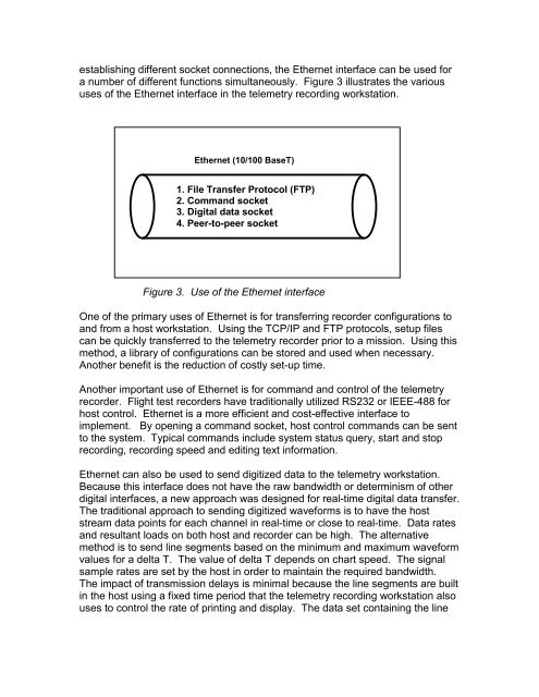
establishing different socket connections, the Ethernet interface can be used for a number of different functions simultaneously. Figure 3 illustrates the various uses of the Ethernet interface in the telemetry recording workstation. Ethernet (10/100 BaseT) 1. File Transfer Protocol (FTP) 2. Command socket 3. Digital data socket 4. Peer-to-peer socket Figure 3. Use of the Ethernet interface One of the primary uses of Ethernet is for transferring recorder configurations to and from a host workstation. Using the TCP/IP and FTP protocols, setup files can be quickly transferred to the telemetry recorder prior to a mission. Using this method, a library of configurations can be stored and used when necessary. Another benefit is the reduction of costly set-up time. Another important use of Ethernet is for command and control of the telemetry recorder. Flight test recorders have traditionally utilized RS232 or IEEE-488 for host control. Ethernet is a more efficient and cost-effective interface to implement. By opening a command socket, host control commands can be sent to the system. Typical commands include system status query, start and stop recording, recording speed and editing text information. Ethernet can also be used to send digitized data to the telemetry workstation. Because this interface does not have the raw bandwidth or determinism of other digital interfaces, a new approach was designed for real-time digital data transfer. The traditional approach to sending digitized waveforms is to have the host stream data points for each channel in real-time or close to real-time. Data rates and resultant loads on both host and recorder can be high. The alternative method is to send line segments based on the minimum and maximum waveform values for a delta T. The value of delta T depends on chart speed. The signal sample rates are set by the host in order to maintain the required bandwidth. The impact of transmission delays is minimal because the line segments are built in the host using a fixed time period that the telemetry recording workstation also uses to control the rate of printing and display. The data set containing the line
segments can include time marks, an IRIG time stamp and grid information that provide the host with expanded control over the chart. One of the most recent advances in the networking aspect of the telemetry recording workstation is peer-to-peer networking. Utilizing the latest peer-to-peer technologies, flight test recorders can now be linked to provide instantaneous communication between systems. This fully distributed, network-based architecture can be used for command and control of multiple recorders, as well as message passing between them. A centralized server is no longer required, resulting in considerable logistical and cost savings. For the flight test engineer, an important application is marking points of interest during real-time and having those areas identified and synchronized on other systems. Another application is having any one of several engineers be able to change the display or chart speed resolution of all connected systems based on a real-time event. Airborne Flight Test Considerations Regarding airborne Flight Test considerations, three mean factors are focused upon: environmental conditions, appropriate user interface and monitoring. Environmental Conditions Telemetry recorder for airborne applications takes into account the compliance with environmental conditions. Airborne recorder design will pay attention to several factors: temperature, altitude and pressure, humidity, vibrations, emission of radio frequency and electrostatic discharge. 3 specific factors are discussed in this paper: temperature, vibrations and emission RF. The use of COTS (Commercial Off-the-Shelf) components is the main problem with temperature device. The typical range for onboard airborne equipment is – 15°C / +55°C and the typical range for COTS components is generally 0°C / 50°C. To deal with this difference, recorder design has to ease thermal dissipation. Air inlets and warming system can also be considered as optional devices. For vibrations factor, the sensitive vertical axis (Z axis) should have an influence in the inner disposition of discrete elements. Attention will also be paid with the choice of connectors. Hardened lockable solution is a basic requirement for connectors. The design of all moving part will be properly studied. Introduction of ruggedized discrete elements can also allow complying with vibrations requirements. The RF emission of the recorder has to comply with airborne general requirement. The equipment must be submitted to category M test “Maximum Level of Radiated RF interference” described in DO160 document.
- Page 174 and 175: Vue f(t) 2.3.1 Vues y=f(t) Ces vues
- Page 176 and 177: Maquette aéronef Alarmes Bar-graph
- Page 178 and 179: 2.3.3 Représentation trajectograph
- Page 180 and 181: 2.3.5 Vidéo Par ailleurs, si le ma
- Page 182 and 183: 3 Concept de structure d’accueil
- Page 184 and 185: 4 Exemples d’utilisation 4.1.1 HB
- Page 186 and 187: SESSION 3 : Capteurs et dispositifs
- Page 188 and 189: BACK THE NEXT GENERATION AIRBORNE D
- Page 190 and 191: 3. DC SPECIFICATIONS - SEEING THE W
- Page 192 and 193: For the purposes of this paper it i
- Page 194 and 195: hardware down and led to widely acc
- Page 196 and 197: mechanism. In a system where a late
- Page 198 and 199: 0 X Y X' Y' 0 X Y Sampling Cycle X
- Page 200 and 201: - Perform the exchange in a rigorou
- Page 202 and 203: GLOSSARY AFDX Avionics Full DupleX
- Page 204 and 205: The complete message is recorded by
- Page 206 and 207: The L3 switches allow forwarding da
- Page 208 and 209: Furthermore, the configuration of t
- Page 210 and 211: BACK LOGICIEL JAVA D’ACQUISITION
- Page 212 and 213: ISA ISA Interface utilisateur Objet
- Page 214 and 215: CONCLUSION La première version de
- Page 216 and 217: ; ( ( + & 2+5. . & & , & . + & +2(
- Page 218 and 219: ( +, & + < 0 9& - & = (( + 1 - + +,
- Page 220 and 221: BACK Telemetry Recording Workstatio
- Page 222 and 223: Figure 1: Real-time pen tip display
- Page 226 and 227: 73 64 63 61 60 48 45 40 35 Level (d
- Page 228 and 229: SESSION 5 : TELEMESURE (SPECTRE - M
- Page 230 and 231: Currently various avenues are explo
- Page 232 and 233: Binary X Binary to RNS and RNS to B
- Page 234 and 235: The index multiplier block will be
- Page 236 and 237: The current implementation consists
- Page 238 and 239: Spécificité de la télémesure AI
- Page 240 and 241: Technique COFDM : La modulation COF
- Page 242 and 243: La réception s’effectue par une
- Page 244 and 245: BACK ETCC'2003 European Test and Te
- Page 246 and 247: ETCC'2003 European Test and Telemet
- Page 248 and 249: ETCC'2003 European Test and Telemet
- Page 250 and 251: ETCC'2003 European Test and Telemet
- Page 252 and 253: SESSION 6 : SYSTEMES DE TELEMESURE
- Page 254 and 255: f f p IF = R b = 4R b ∆f = 0. 7R
- Page 256 and 257: 2.3 ADC Fig.5 (a) y (t) and its spe
- Page 258 and 259: 2.5 FM demodulation Fig.9 I ‘(nT1
- Page 260 and 261: References 1. Gardner FM. A BPSK/QP
- Page 262 and 263: L/S/C /X/Ku /Ka band Spacelink Syst
- Page 264 and 265: Spacelink System - The solution for
- Page 266 and 267: SPOT Σ ∆ X band feed Data LNA Tr
- Page 268 and 269: défilant. Le cahier des charges d
- Page 270 and 271: TOURELLE HEXAPODE La tourelle hexap
- Page 272 and 273: Ci après, tableau des spécificati
establishing different socket connections, the Ethernet interface can be used for<br />
a number of different functions simultaneously. Figure 3 illustrates the various<br />
uses of the Ethernet interface in the telemetry recording workstation.<br />
Ethernet (10/100 BaseT)<br />
1. File Transfer Protocol (FTP)<br />
2. Command socket<br />
3. Digital data socket<br />
4. Peer-to-peer socket<br />
Figure 3. Use of the Ethernet interface<br />
One of the primary uses of Ethernet is for transferring recorder configurations to<br />
and from a host workstation. Using the TCP/IP and FTP protocols, setup files<br />
can be quickly transferred to the telemetry recorder prior to a mission. Using this<br />
method, a library of configurations can be stored and used when necessary.<br />
Another benefit is the reduction of costly set-up time.<br />
Another important use of Ethernet is for command and control of the telemetry<br />
recorder. Flight test recorders have traditionally utilized RS232 or IEEE-488 for<br />
host control. Ethernet is a more efficient and cost-effective interface to<br />
implement. By opening a command socket, host control commands can be sent<br />
to the system. Typical commands include system status query, start and stop<br />
recording, recording speed and editing text information.<br />
Ethernet can also be used to send digitized data to the telemetry workstation.<br />
Because this interface does not have the raw bandwidth or determinism of other<br />
digital interfaces, a new approach was designed for real-time digital data transfer.<br />
The traditional approach to sending digitized waveforms is to have the host<br />
stream data points for each channel in real-time or close to real-time. Data rates<br />
and resultant loads on both host and recorder can be high. The alternative<br />
method is to send line segments based on the minimum and maximum waveform<br />
values for a delta T. The value of delta T depends on chart speed. The signal<br />
sample rates are set by the host in order to maintain the required bandwidth.<br />
The impact of transmission delays is minimal because the line segments are built<br />
in the host using a fixed time period that the telemetry recording workstation also<br />
uses to control the rate of printing and display. The data set containing the line


