D Montage- und Bedienungsanleitung für ABUS Fenster ...
D Montage- und Bedienungsanleitung für ABUS Fenster ...
D Montage- und Bedienungsanleitung für ABUS Fenster ...

You also want an ePaper? Increase the reach of your titles
YUMPU automatically turns print PDFs into web optimized ePapers that Google loves.
Abb./fig./schéma/afb./ill. 2<br />
FAS<br />
8<br />
7<br />
DFS<br />
DFS<br />
Abb./fig./schéma/afb./ill. 3<br />
6<br />
2<br />
5<br />
D <strong>Montage</strong>- <strong>und</strong> <strong>Bedienungsanleitung</strong> <strong>für</strong> <strong>ABUS</strong> <strong>Fenster</strong>-Doppelflügel-Schloss DFS 95<br />
G Assembly and Operating Instructions for <strong>ABUS</strong> Double Casement Window Lock DFS 95<br />
FAS<br />
3<br />
106<br />
Abb./fig./schéma/afb./ill. 1<br />
1<br />
58<br />
<strong>Fenster</strong>flügel<br />
Window<br />
Battant de fenêtre<br />
Raam<br />
Battente<br />
17<br />
<strong>Fenster</strong>rahmen<br />
Frame<br />
Cadre<br />
Kozijn<br />
Telaio<br />
2<br />
4<br />
58<br />
max. 29<br />
5<br />
4<br />
60<br />
40<br />
D Diese Anleitung ist wie folgt untergliedert:<br />
I. Allgemeine Hinweise IV. Werkzeug<br />
II. Einsatzmöglichkeit V. <strong>Montage</strong>anleitung<br />
III. Packungsinhalt VI. Bedienung<br />
I. Allgemeine Hinweise<br />
Das <strong>Fenster</strong>-Doppelflügelschloss ist nach den strengen Prüfanforderungen<br />
der DIN 18104-1 <strong>und</strong> VdS 2536 anerkannt. Durch DIN Certco ist DFS 95<br />
zertifiziert „EINBRUCHHEMMEND DIN-geprüft“. DFS 95 bietet zusätzlich<br />
Schutz gegen unberechtigtes Eindringen in ihre Räume. Gemäß DIN 18104-1<br />
wird empfohlen, dass pro 1 Meter <strong>Fenster</strong>höhe rechts <strong>und</strong> links jeweils eine<br />
Zusatzsicherung montiert wird (pro <strong>Fenster</strong>). Polizei <strong>und</strong> Versicherer empfehlen<br />
dieses ebenfalls.<br />
Die optimale Schutzwirkung erreichen Sie, wenn Sie entsprechend dieser<br />
<strong>Montage</strong>- <strong>und</strong> <strong>Bedienungsanleitung</strong> vorgehen. Die Befestigungsschrauben<br />
sollten zur Vermeidung von Überdrehung mit einem geeigneten Werkzeug<br />
eingeschraubt <strong>und</strong> von Hand angezogen werden. Ausschließlich <strong>ABUS</strong>-<br />
Befestigungsmaterial einsetzen.<br />
Für eventuell auftretende Verletzungen bzw. Schäden, die bei der <strong>Montage</strong><br />
<strong>und</strong>/oder durch unsachgemäße Handhabung entstehen, übernimmt der<br />
Hersteller keine Haftung!<br />
Ein Zugang des gesamten Objektes muss von außen mittels Schlüssel zu<br />
öffnen sein.<br />
II. Einsatzmöglichkeit<br />
DFS 95 eignet sich <strong>für</strong> Doppelflügelfenster oder <strong>Fenster</strong>türen mit einem<br />
Abstand zwischen den Flügeln von 18–35 mm <strong>und</strong> eignet sich <strong>für</strong> alle<br />
gängigen nach innen öffnende <strong>Fenster</strong>/<strong>Fenster</strong>türen mit Dreh- oder Dreh-<br />
Kipp-Beschlägen (Abb. 2). Die <strong>Montage</strong> kann auf den Werkstoffen Kunststoff,<br />
Holz oder Alu erfolgen. Die <strong>Fenster</strong>/<strong>Fenster</strong>türen können nach rechts oder<br />
links öffnen.<br />
DFS 95 wird gr<strong>und</strong>sätzlich auf der Innenseite montiert, der Schlosskasten<br />
auf dem Mittelsteg <strong>und</strong> die Schließkästen auf den Flügeln.<br />
Bei schlechten Befestigungsmöglichkeiten (Weichholz- oder Kunststofffenster)<br />
sollten mehrere Sicherungen <strong>und</strong> zusätzlich Befestigungsmittel (Befestigungsanker<br />
oder Verb<strong>und</strong>mörtel) eingesetzt werden. Hierzu verwenden Sie bitte<br />
den <strong>ABUS</strong>-Befestigungsanker BA (Kunststoff-, Weichholz-, Alufenster)<br />
oder alternativ das <strong>ABUS</strong>-Befestigungsset IM 100 (Kunststofffenster).<br />
Zu IM 100 benötigen Sie einen geeigneten Verb<strong>und</strong>mörtel,<br />
z.B. der Marke Fischer FIS VS 150C, Hilti HFX oder ein ähnliches Produkt.<br />
<strong>ABUS</strong> BA <strong>und</strong> <strong>ABUS</strong> IM 100 sowie Verb<strong>und</strong>mörtel sind im Handel erhältlich.<br />
Die in Abb. 2 zusätzlich gezeigten <strong>ABUS</strong>-Produkte (FAS) sind ebenfalls im<br />
Handel erhältlich.<br />
III. Packungsinhalt (Abb. 3)<br />
1. 1 Schlosskasten mit Drehknopf<br />
2. 2 Schließplatten<br />
3. 1 Anschraubleiste<br />
4. 2 Abdeckkappen Schlosskasten<br />
5. 2 Abdeckkappen Schließplatten<br />
6. 1 Satz Unterlagen je 1x1 mm, 2 mm, 4 mm, 8 mm<br />
7. 1 Satz Unterlagen Schließplatten 2 x1 mm, 1x 2 mm<br />
8. Schrauben:<br />
1 Stück 5,5 x 80 mm<br />
3 Stück 5,5 x 60 mm<br />
4 Stück 5,5 x 50 mm<br />
1 Stück M6 x 45 mm<br />
1 Stück M6 x 30 mm<br />
1 Stück Unterlegscheibe<br />
IV. <strong>Montage</strong>werkzeug<br />
Kreuzschlitzschraubendreher<br />
Bohrmaschine<br />
Feile, Säge zum Kürzen der Schrauben, ggf. Schraubstock<br />
Inbusschlüssel SW 4<br />
Bohrtabelle<br />
<strong>für</strong><br />
Schrauben<br />
Ø<br />
5,5 mm<br />
In Holz <strong>und</strong> Kunststoff<br />
ohne Metalleinlage<br />
Bohrer Ø<br />
4,0 mm 4,5 mm<br />
In Alu <strong>und</strong> Kunststoff<br />
mit Metalleinlage<br />
Bohrer Ø<br />
G The instructions contain the following chapters:<br />
I. General Notes IV. Tools<br />
II. Applications V. Assembly Instructions<br />
III. Delivery Package VI. Operation<br />
I. General Notes<br />
The DFS 95 double casement window lock is certified to meet the strict<br />
testing requirements of DIN 18104-1 and VdS 2536. The DFS 95 is certified<br />
to be “BURGLARY-RESISTANT DIN tested” by DIN Certco. Additionally,<br />
the DFS 95 provides protection against unauthorised access to your rooms.<br />
DIN 18104-1 recommends that an additional security device should<br />
be fitted on the left and right for every meter in height (per window).<br />
The police and insurance companies also give the same recommendation.<br />
Optimal protection is provided if you follow these assembly and operating<br />
instructions. To prevent overturning, the fastening screws should be<br />
screwed in with a suitable tool and tightened by hand. Only use <strong>ABUS</strong><br />
fastening material.<br />
The manufacturer cannot be held liable for any injury or damage caused<br />
during assembly and/or by inexpert handling!<br />
It must be possible to open one access point to the entire object from the<br />
outside using a key.<br />
II. Applications<br />
The DFS 95 is suitable for double casement windows or French windows<br />
with casement gaps of between 18 and 35 mm and is suitable for all<br />
usual commercial windows/French windows opening inwards with<br />
side/centre hung fittings (fig. 2).<br />
The locks can be installed on plastic, wood or aluminium.<br />
The windows/French windows may open to the left or right side.<br />
The DFS 95 is as a rule mounted on the inside, the lock case on the centre<br />
web and the casings of the lock on the wings.<br />
If the fastening is problematic (soft wood or plastic windows),<br />
then several retention devices and additional means of fastening<br />
(fastening anchor or binding mortar) should be used.<br />
Please use the <strong>ABUS</strong> fastening anchor BA (plastic, soft wood, aluminium<br />
windows) or the <strong>ABUS</strong> fastening set IM 100 (plastic windows).<br />
The IM 100 requires a suitable binding mortar e.g. Fischer FIS VS 150C,<br />
Hilti HFX or a similar product.<br />
<strong>ABUS</strong> BA and <strong>ABUS</strong> IM 100 and binding mortar are available from dealers.<br />
The additional <strong>ABUS</strong> products (FAS) shown in fig. 2 are also available<br />
from dealers.<br />
III. Delivery Package (fig. 3)<br />
1. 1 lock case with handle<br />
2. 2 striking plates<br />
3. 1 screw-on rail<br />
4. 2 covers for lock case<br />
5. 2 covers for striking plates<br />
6. 1 set of spacers 1x1 mm, 2 mm, 4 mm, 8 mm<br />
7. 1 set of spacers for striking plates 2 x1 mm, 1x 2 mm<br />
8. Screws:<br />
1 piece 5.5 x 80 mm<br />
3 pieces 5.5 x 60 mm<br />
4 pieces 5.5 x 50 mm<br />
1 piece M6 x 45 mm<br />
1 piece M6 x 30 mm<br />
1 washer<br />
IV. Assembly Tools<br />
Cross-tip screwdriver<br />
Drilling machine<br />
File, saw for cutting screws to size, maybe vice<br />
Allen key, size 4<br />
Drilling table<br />
for<br />
screws<br />
Ø<br />
5.5 mm<br />
in wood and PVC<br />
without metal inlay<br />
drill bit Ø<br />
4.0 mm 4.5 mm<br />
in aluminium and PVC<br />
with metal inlay<br />
drill bit Ø
F Ce manuel comporte les chapitres suivants:<br />
I. Informations générales IV. Outils requis<br />
II. Application V. Instructions de montage<br />
III. Liste de colisage VI. Maniement<br />
I. Informations générales<br />
La serrure DFS 95 spécialement conçue pour fenêtres à double battant répond<br />
aux exigences particulièrement sévères du contrôle effectué conformément<br />
à la DIN 18104-1et est agréé conformément à la norme VdS 2536.<br />
Par ailleurs, la serrure DFS 95 a fait l’objet d’un contrôle DIN Certco<br />
et a obtenu la mention «anti-effraction selon la DIN». La serrure DFS 95<br />
assure une protection supplémentaire contre toute pénétration non-souhaitée<br />
dans vos locaux. Selon la norme DIN 18104-1, il est recommandé de monter<br />
une protection complémentaire par mètre de hauteur de fenêtre, à gauche<br />
comme à droite (par fenêtre). La police et les compagnies d’assurance le<br />
recommandent également.<br />
C’est en vous conformant strictement aux présentes instructions de montage<br />
et de service, que vous obtiendrez une sécurité optimale. Afin de prévenir tout<br />
forçage, nous vous conseillons de fixer les vis de fixation en utilisant un outil<br />
adéquat et de les serrer manuellement. Il est impératif d’utiliser le matériel de<br />
fixation Abus à l’exclusion de tout autre.<br />
En aucun cas, le fabricant ne saurait être tenu pour responsable de blessures<br />
ou de dommages survenant en cours de montage et/ou résultant d’un<br />
maniement inadéquat.<br />
L’accès de l’objet dans son ensemble doit être assuré par un déverrouillage<br />
extérieur au moyen d’une clé.<br />
II. Application<br />
La serrure DFS 95 s’adapte à toutes les fenêtres à double battant ou à<br />
toutes les portes-fenêtres dont les battants présentent un écartement compris<br />
entre 18 et 35 mm. Par ailleurs, elle s’adapte à toutes les fenêtres/portesfenêtres<br />
ouvrant vers l’intérieur et munies de ferrures basculantes ou<br />
oscillobattantes habituellement commercialisées (cf. schéma 2).<br />
Le montage est autorisé sur des cadres en PVC, en bois ou en aluminium.<br />
Les fenêtres/portes-fenêtres peuvent s’ouvrir vers la droite ou vers la gauche.<br />
Le montage de la serrure DFS 95 se fait toujours du côté intérieur, le boîtier<br />
venant se positionner sur l’entretoise médiane et les gâches sur les battants.<br />
Lorsque les possibilités de fixation sont insatisfaisantes (bois tendre ou fenêtres<br />
en PVC), nous conseillons le montage de plusieurs dispositifs de sécurité ainsi<br />
que l’utilisation de moyens de fixation supplémentaires (ancre de fixation ou<br />
mortier). A cet effet, nous vous recommandons l’utilisation de l’ancre de<br />
fixation BA de <strong>ABUS</strong> (pour les fenêtres en PVC, en bois tendre ou en<br />
aluminium) ou le set de fixation <strong>ABUS</strong> IM 100 (pour les fenêtres en PVC).<br />
Si vous choisissez d’utiliser le set de fixation IM 100, il vous faut un mortier<br />
adéquat des marques Fischer FIS VS 150C, Hilti HFX ou un produit similaire.<br />
Vous pouvez vous procurer les dispositifs <strong>ABUS</strong> BA et <strong>ABUS</strong> IM 100 ainsi<br />
que le mortier adéquat chez votre commerçant spécialisé.<br />
Les produits <strong>ABUS</strong> figurant au schéma 2 sont également disponibles dans<br />
tous les commerces spécialisés.<br />
III. Liste de colisage (schéma 3)<br />
1. 1 boîtier à bouton tournant<br />
2. 2 gâches d’ancrage<br />
3. 1 socle de fixation<br />
4. 2 caches pour boîtier<br />
5. 2 caches pour gâches<br />
6. 1 jeu de cales de respectivement 1x1 mm, 2 mm, 4 mm, 8 mm<br />
7. 1 jeu de cales pour gâches 2 x1 mm, 1x 2 mm<br />
8. Vis<br />
1 vis 5,5 x 80 mm 1 vis M6 x 45 mm<br />
3 vis 5,5 x 60 mm 1 vis M6 x 30 mm<br />
4 vis 5,5 x 50 mm 1 rondelle<br />
IV. Outils requis pour le montage<br />
Tournevis cruciforme<br />
Perceuse<br />
Lime, scie pour raccourcir les vis, étau, le cas échéant<br />
Clé à six pans creux SW4<br />
Tableau de perçage<br />
pour<br />
vis<br />
Ø<br />
5,5 mm<br />
dans châssis bois et<br />
PVC sans âme métallique<br />
foret Ø<br />
4,0 mm 4,5 mm<br />
F Instructions de montage <strong>ABUS</strong> DFS 95 spécialement conçue pour fenêtres à double battant<br />
n <strong>Montage</strong>-en bedieningsinstructie voor <strong>ABUS</strong> raamslot DFS 95<br />
I Istruzioni di montaggio ed uso della serratura per finestre doppie DFS 95<br />
dans châssis aluminium et<br />
PVC avec âme métallique<br />
foret Ø<br />
n Index: gebruik montage- en bedieningsinstructie:<br />
I. Algemeen IV. Gereedschap<br />
II. Toepassing V. <strong>Montage</strong><br />
III. Verpakkingsinhoud VI. Bediening<br />
I. Algemeen<br />
Bijzetgrendel voor naar binnen draaiende dubbele (draai/kiep) ramen<br />
(stolpramen). DFS 95 is volgens keuringseisen NEN 5096 SKG gecertificeerd.<br />
De DFS 95 biedt daarnaast bescherming tegen onbevoegd binnendringen<br />
van uw woning. Advies: monteer aan de sluitzijde voor maximale veiligheid<br />
2 stuks per 1 meter raamhoogte. Op kunststof zonder metalen kern dient<br />
u dit slot in combinatie met <strong>ABUS</strong> BA bevestigingsanker te monteren.<br />
Optioneel verkrijgbaar, zie voor montage in de handleiding van BA.<br />
Optimale veiligheid wordt bereikt door nauwkeurig opvolgen van<br />
deze montage- en gebruiksaanwijzing. Om overexpansie of doldraaien<br />
van de bevestigingsschroeven te vermijden, draait u handmatig en met<br />
passend gereedschap de schroeven vast.<br />
Voor eventuele verwondingen en/of schade tijdens montage en/of gebruik<br />
aanvaardt de fabrikant geen enkele aansprakelijkheid!<br />
II. Toepassing<br />
De DFS 95 is geschikt voor naar binnen draaiende dubbele (draai/kiep) ramen<br />
met een tussenstijl/tussenruimte van 18 – 35 mm (afb. 2).<br />
Zowel voor kunststof, hout en aluminium, rechts of links draaiend.<br />
DFS 95 wordt uitsluitend aan de binnenzijde gemonteerd; de slotkast<br />
op de tussenstijl (met bevestigingsanker BA) en de sluitplaten op de ramen.<br />
Bij slechte bevestigingsmogelijkheden (zacht hout, aluminium of kunststof<br />
zonder metalen kern) sloten monteren met extra bevestigingsmiddelen.<br />
Gebruik hiervoor <strong>ABUS</strong> bevestigingsanker BA.<br />
Of als alternatief de <strong>ABUS</strong>-bevestigingsset IM 100 in combinatie met een<br />
passend chemisch anker, bijv. Fischer FIS VS 150C, Hilti HFX of vergelijkbaar.<br />
<strong>ABUS</strong> BA, <strong>ABUS</strong> IM 100 en chemische ankers zijn in de handel verkrijgbaar.<br />
In afb. 2 aangegeven <strong>ABUS</strong> producten (FAS scharnierbeveiligers) zijn in de<br />
handel verkrijgbaar.<br />
III. Verpakkingsinhoud (afb. 3)<br />
1. 1 slotkast met draaiknop<br />
2. 2 sluitplaten<br />
3. 1 montageplaat<br />
4. 2 afdekkapjes slotkast<br />
5. 2 afdekkappen sluitplaten<br />
6. 1 set opvulplaatjes voor slotkast 1, 2, 4, 8 mm<br />
7. 1 set opvulplaatjes sluitplaten 1, 2 mm<br />
8. Schroeven/bouten:<br />
1 5,5 x 80 mm<br />
3 5,5 x 60 mm<br />
4 5,5 x 50 mm<br />
1 M6 x 45 mm<br />
1 M6 x 30 mm<br />
1 sluitring<br />
IV. Gereedschap<br />
Kruiskopschroevendraaier<br />
Boormachine, boren zie tabel<br />
Vijl, zaag en eventueel een bankschroef voor het inkorten van de schroeven<br />
Inbussleutel 4 mm<br />
Boortabel<br />
voor<br />
schroef<br />
Ø<br />
5,5 mm<br />
in hout en kunststof<br />
zonder metalen kern<br />
boor Ø<br />
4,0 mm 4,5 mm<br />
in aluminium en kunststof<br />
met metalen kern<br />
boor Ø<br />
I Queste istruzioni si suddividono in modo seguente:<br />
I. Istruzioni generali IV. Attrezzi<br />
II. Possibilità d’impiego V. Istruzioni di montaggio<br />
III. Contenuto della confezione VI. Uso<br />
I. Istruzioni generali<br />
La serratura per finestre doppie è conforme ai severi requisiti<br />
di controllo della DIN 18104-1 e VdS 2536.<br />
Con la DIN Certco essa è certificata «ANTISCASSO conf. DIN».<br />
La DFS 95garantisce una protezione in più a difesa della Vostra casa.<br />
Secondo DIN 18104-1 si consiglia di montare per ogni metro di<br />
altezza della finestra, una sicura supplementare sul lato destro e una<br />
sul lato sinistro (per ogni finestra). Anche la polizia e le compagnie<br />
d’assicurazione consigliano tali misure.<br />
Si può ottenere una protezione ottimale, procedendo secondo queste<br />
istruzioni di montaggio ed uso. Le viti di fissaggio, per evitarne un serraggio<br />
eccessivo,devono essere avvitate con un utensile adatto e poi serrate a mano.<br />
Impiegare esclusivamente materiale di fissaggio <strong>ABUS</strong>.<br />
Per eventuali ferimenti e/o danni, che si verificano durante il montaggio e/o<br />
per maneggio indebito, il produttore non si assume alcuna responsabilità!<br />
Un accesso a chiave deve essere garantito a ogni momento.<br />
II. Possibilità d’impiego<br />
La sicura DFS 95 e adatta per finestre doppie o portefinestre con un spazio<br />
di 18 – 35mm tra di loro ed è adatta per tutte le finestre e porte-finestre che<br />
si aprono verso l’interno, con ferramenti girevoli o girevolia bilico (ill. 2).<br />
Si può montare la DFS 95 su legno, plastica o alluminio.<br />
Le finestre o porte-finestre possono aprirsi verso destra o sinistra.<br />
Di solito la DFS 95 viene montata all’interno, la lamiera del battente sul<br />
battente della finestra ed il listello del telaio sul telaio.<br />
Se le possibilità di fissaggio sono scadenti (sottofondo morbido o vuoto<br />
o riempito con espanso e finestre in plastica con o senza inserto metallico<br />
e finestre in legno) e le possibilità di effrazione dall’esterno sono buone,<br />
si dovrebbe utilizzare più sicure e mezzi di fissaggio supplementari<br />
(malta o avvitamento passante o bullone di fissaggio).<br />
Allo scopo utilizzare per favore il bullone di fissaggio <strong>ABUS</strong> BA o come<br />
alternativa nel caso di telai in plastica il kit di fissaggio <strong>ABUS</strong> IM 100.<br />
Per il IM 100 serve una malta adatta, p.e. della marca Fischer FIS VS 150 C<br />
o un prodotto simile. <strong>ABUS</strong> BA e <strong>ABUS</strong> IM 100 come anche la malta si possono<br />
acquistare in commercio.<br />
III. Contenuto della confezione (ill. 3)<br />
1. 1 cassa di serratura<br />
2. 2 lamiere di chiusura<br />
3. 1 listello di montaggio<br />
4. 2 coperture per la cassa di serratura<br />
5. 2 copperchietti per le lamiere di chiusura<br />
6. 1 set spessori di 1x1mm, 2mm, 4mm, 8mm<br />
7. 1 set di spessori per le lamiere di chiusura 2 x1mm, 1x 2mm<br />
8. Viti:<br />
1 vite da 5,5 x 80mm<br />
3 viti da 5,5 x 60mm<br />
4 viti da 5,5 x 50mm<br />
1 vite da M6 x 45mm<br />
1 vite da M6 x 30mm<br />
1 spessore<br />
IV. Attrezzi da montaggio<br />
Cacciavite a croce<br />
Trapano<br />
Lima, sega per accorciare le viti, in caso morsa<br />
Chiave ad esagono incassato SW 4<br />
Tabella per trapanazioni<br />
per<br />
viti<br />
Ø<br />
5,5 mm<br />
in legno e plastica<br />
senza inserto metallico<br />
punta da trapano Ø<br />
4,0 mm 4,5 mm<br />
in alluminio e plastica<br />
con inserto metallico<br />
punta da trapano Ø
Abb./fig.<br />
schéma<br />
afb./ill. 4<br />
Abb./fig./schéma/afb./ill. 5<br />
Abb./fig./schéma/afb./ill. 6 Abb./fig./schéma/afb./ill. 7<br />
Abb./fig./schéma/afb./ill. 8 Abb./fig./schéma/afb./ill. 9<br />
c<br />
a<br />
b<br />
a<br />
a<br />
b<br />
Abb./fig.<br />
schéma<br />
afb./ill. 4a<br />
1 mm<br />
<strong>ABUS</strong> - Das gute Gefühl der Sicherheit<br />
D Technische Änderungen vorbehalten. Für Irrtümer <strong>und</strong> Druckfehler keine Haftung. <strong>ABUS</strong> © 2006<br />
G Subject to technical alterations. No liability for mistakes and printing errors. <strong>ABUS</strong> © 2006<br />
a<br />
b<br />
a<br />
a<br />
b<br />
Kunststoffunterlage<br />
Spacers / Cales de respectivement<br />
Opvulplaatjes / Spessori<br />
<strong>Fenster</strong>flügel<br />
Window<br />
Cadre<br />
Raamvleugel<br />
Battente<br />
<strong>Fenster</strong>flügel<br />
Window<br />
Cadre<br />
Raamvleugel<br />
Battente<br />
Anschraubleiste<br />
Screw-on rail / Barre de vissage<br />
<strong>Montage</strong>plaat / Listello di montaggio<br />
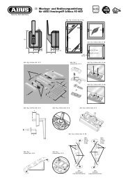
D V. <strong>Montage</strong>anleitung:<br />
Wichtige Hinweise:<br />
• Vor der <strong>Montage</strong> prüfen Sie bitte die Einstellung des <strong>Fenster</strong>s bzw.<br />
der <strong>Fenster</strong>tür. Stellen Sie sicher, dass sich das <strong>Fenster</strong>/die <strong>Fenster</strong>tür<br />
einwandfrei öffnen <strong>und</strong> schließen lässt.<br />
• Messen Sie auch nach, ob die in Abb. 1 angegebenen Mindestmaße<br />
an Ihrem <strong>Fenster</strong>/Ihrer <strong>Fenster</strong>tür vorhanden sind.<br />
• Die Bohrlochtiefen bzw. die Schraubenlängen müssen auf die örtlichen<br />
Gegebenheiten abgestimmt werden.<br />
• Austreten des Bohrers bzw. der Schrauben auf der Rückseite<br />
vermeiden! Ggf. mit Bohranschlag arbeiten oder die vorhandenen<br />
Schrauben kürzen.<br />
• Beim Bohren keine beweglichen Teile, Dichtungen oder Glasscheiben<br />
verletzen.<br />
<strong>Montage</strong>:<br />
<strong>Montage</strong> ab 14 mm Falzstärke<br />
1. Anschraubleiste (3) in gewünschter Höhe (halbe Höhe zwischen <strong>Fenster</strong>griff<br />
<strong>und</strong> Unterkante des <strong>Fenster</strong>flügels) mittig zwischen den <strong>Fenster</strong>flügeln<br />
anhalten. Halbmondnocken nach oben. Bohrungen (a) anzeichnen<br />
(Abb. 4) <strong>und</strong> vorbohren (s. Bohrtabelle).<br />
2. Anschraubleiste (3) mit Unterlagen (6) soweit unterfüttern,<br />
bis Oberkante Anschraubleiste (3) <strong>und</strong> Oberkante <strong>Fenster</strong>flügel<br />
auf einer Ebene liegen (Abb. 4a + 5). Bei Falzdickenunterschiede<br />
der beiden <strong>Fenster</strong>flügel die Oberkante des dickeren Falzes auswählen.<br />
Anschraubleiste (3) mit Unterlagen (6) mit den Schrauben 5,5 x 60 mm<br />
anschrauben (Bohrlöcher a).<br />
3. Schraubabdeckungen (4) des Schlosskastens (1) von unten ausstoßen.<br />
Schlosskasten (1) mit Schrauben M6 x 30 mm <strong>und</strong> M6 x 45 mm mit<br />
U-Scheibe auf die Anschraubleiste (3) schrauben (Abb. 6).<br />
<strong>Montage</strong> von 0 –13 mm Falzstärke<br />
1. Anschraubleiste (3) in gewünschter Höhe (halbe Höhe zwischen <strong>Fenster</strong>griff<br />
<strong>und</strong> Unterkante des <strong>Fenster</strong>flügels) mittig zwischen den <strong>Fenster</strong>flügeln<br />
anhalten. Halbmondnocken nach oben. Bohrungen (b) anzeichnen<br />
(Abb. 4) <strong>und</strong> vorbohren (s Bohrtabelle).<br />
2. Schraubenabdeckungen (4) des Schlosskastens (1) von unten ausstoßen.<br />
Schlosskasten (1) je nach Falzstärke mit den Unterlagen (6) unterfüttern<br />
(Halbmondnocken nach oben). Bei Falzdickenunterschiede der beiden<br />
<strong>Fenster</strong>flügel die Oberkante des dickeren Falzes auswählen. Mit Schrauben<br />
5,5 x 60 mm <strong>und</strong> 5,5 x 80 mm mit U-Scheibe anschrauben (Abb. 7).<br />
<strong>Montage</strong> der Schließplatten<br />
1. Abdeckkappen (5) mit Schraubendreher von den Schließplatten (2) lösen.<br />
Hierbei von der offenen Seite mit dem Schraubendreher zwischen Metallnase<br />
<strong>und</strong> Haube ansetzen <strong>und</strong> die Teile auseinander drücken.<br />
2. Schließplatten (2) (Abb. 8) auf die <strong>Fenster</strong>flügel legen <strong>und</strong> im Abstand<br />
von 1 mm an den Schlosskasten (1) halten. Bei Falzdickenunterschiede<br />
der beiden <strong>Fenster</strong>flügel Schließplatten <strong>für</strong> den dünneren Falz mit Unterlagen<br />
ausgleichen. Riegelfunktion prüfen. Schlüssel einstecken <strong>und</strong> um<br />
90° drehen. Je 1 der 3 Bohrlöcher „c“ oben <strong>und</strong> unten anzeichnen<br />
<strong>und</strong> vorbohren (s. Bohrtabelle). Schließplatten (2) mit den Schrauben<br />
5,5 x 50 mm anschrauben.<br />
3. Funktion des Schlosses überprüfen. Schraubenabdeckungen (4)<br />
(Abb. 6 +7) aufdrücken. Abdeckkappen (5) auf Schließplatten (2)<br />
aufdrücken (Abb. 8 + 9).<br />
Hinweis:<br />
Nach dem Entriegeln durch den Schlüssel ist der Drehknopf unbedingt<br />
senkrecht zu stellen <strong>und</strong> der Schlüssel abzuziehen, da der Drehknopf<br />
sonst nicht blockiert ist.<br />
<strong>ABUS</strong> empfiehlt zur Sicherung der Scharnierseite den Einbau der<br />
<strong>ABUS</strong>-Scharnierseiten-Sicherungen FAS 97 oder FAS 101.<br />
VI. Bedienung<br />
Die Verriegelung des Schlosses erfolgt ohne Schlüssel durch 1 /4-Drehung<br />
des Kunststoffknopfes. Der Mechanismus rastet hörbar ein.<br />
Entriegelung: Schlüssel einstecken <strong>und</strong> um 90° drehen.<br />
Drehknopf senkrecht stellen, Schlüssel zurückdrehen <strong>und</strong> abziehen.<br />
G V. Assembly Instructions:<br />
Important notes:<br />
• Prior to assembly, please check the adjustment of the window<br />
or French window. Make sure that the window/French window<br />
can be opened and closed correctly.<br />
• Check that the min. dimensions shown in fig. 1 apply to your<br />
window or French window.<br />
• The drill hole depths or screw lengths must be adjusted to local<br />
conditions.<br />
• Avoid the drill bit or screws coming out on the rear sides!<br />
If necessary, use a bit stop or cut the screws to size.<br />
• Do not damage any moving parts, seals or glass panes when drilling.<br />
Assembly:<br />
Rebate 14 mm<br />
1. Hold screw-on rail (3) at desired height (half height between window<br />
handle and lower edge of the window casement) centre between the<br />
window casements. Crescent cams facing up. Mark holes (a) (fig. 4)<br />
and drill (see Drilling Table).<br />
2. Place spacers (6) <strong>und</strong>er screw-on rail (3) until upper edge of screw-on<br />
rail (3) and upper edge of window casement are flush (fig. 4a + 5).<br />
If the casements have different rebate sizes, select the upper edge of<br />
the thicker rebate. Fasten screw-on rail (3) with spacers (6) with screws<br />
5.5 x 60 mm (drill holes a).<br />
3. Eject screw covers (4) of the lock case (1) from below. Fasten lock case (1)<br />
with screws M 6 x 30 and M 6x 45 with washer to the screw-on rail (3)<br />
(fig. 6).<br />
Rebate 0 –13 mm<br />
1. Hold screw-on rail (3) at desired height (half height between window<br />
handle and lower edge of the window casement) centre between the<br />
window casements. Crescent cam facing up. Mark holes (b) (fig. 4)<br />
and drill (see Drilling Table).<br />
2. Eject screw covers (4) of the lock case (1) from below. Back lock case (1)<br />
with spacers (6) depending on rebate size (crescent cams facing up).<br />
If the casements have different rebate sizes, select the upper edge of<br />
the thicker rebate. Fasten with screws 5.5 x 60 mm and 5.5 x 80 mm<br />
with washer (fig. 7).<br />
Assembly of the striking plates<br />
1. Remove covers (5) from the striking plates (2) using a screwdriver.<br />
Apply the screwdriver from the open side between metal nose and hood<br />
and press the parts apart.<br />
2. Place the striking plates (2) (fig. 8) onto the window casements and hold<br />
them 1 mm away from the lock case (1). If the rebates of the casements<br />
have different sizes, equalise the striking plates for the thinner rebate<br />
using spacers. Check bolt function. Insert key and turn 90°. Mark one<br />
of the three holes “c” each top and bottom and drill (see Drilling Table).<br />
Fasten striking plates (2) with screws 5.5 x 50 mm.<br />
3. Check the function of the lock. Press on the screw covers (4) (fig. 6 +7).<br />
Press the covers (5) onto the striking plates (2) (fig. 8 + 9).<br />
Note:<br />
After unlocking with the key, make sure to place the handle in vertical<br />
position and draw the key, because otherwise the handle will not be<br />
blocked.<br />
<strong>ABUS</strong> recommends to install <strong>ABUS</strong> hinge side security devices FAS 97 or<br />
FAS 101 to protect the hinge side.<br />
VI. Operation<br />
The lock is latched without key with a quarter turn of the plastic handle.<br />
The mechanism locks audibly. To unlock, insert key and turn 90°.<br />
Place handle upright, turn key back and draw key out.<br />
www.abus.com<br />
390229 5/06
F V. Instructions de montage:<br />
Observations importantes:<br />
• Avant tout montage, il convient de contrôler l’ajustement et l’orientation<br />
corrects des fenêtres ou des portes-fenêtres. Nous vous conseillons de vous<br />
assurer que la fenêtre/la porte-fenêtre s’ouvre et se ferme irréprochablement.<br />
• Nous vous conseillons également de vérifier si votre fenêtre ou votre portefenêtre<br />
présente les dimensions minimales telles qu’indiquées au schéma 1.<br />
• La profondeur des trous de forage ou la longueur des vis doit être adaptée<br />
aux conditions que vous rencontrez sur site.<br />
• Il convient impérativement de prévenir tout affleurement de la perceuse<br />
ou des vis sur la face arrière. Le cas échéant, nous vous conseillons d’utiliser<br />
une butée ou de raccourcir les vis fournies.<br />
• Veillez également à ne pas endommager les parties mobiles, les joints ou<br />
les vitres lors du perçage.<br />
<strong>Montage</strong>:<br />
<strong>Montage</strong> à partir d’un recouvrement de 14 mm<br />
1. Positionnez le socle de fixation (3) à la hauteur souhaitée (à mi-hauteur entre<br />
la poignée de la fenêtre et le bord inférieur du battant) en le centrant entre les<br />
battants de votre fenêtre. Les cames en demi-lune vers le haut.<br />
Marquez les forures (a) (cf. schéma 4) et procédez au perçage des avant-trous<br />
(cf. tableau de perçage).<br />
2. Glissez les cales (6) sous le socle de fixation (3) jusqu’à ce que le bord supérieur<br />
du socle de fixation (3) soit au même niveau que le bord supérieur du battant<br />
de la fenêtre (cf. schémas 4a + 5). Lorsque les deux battants de votre fenêtre<br />
présentent des recouvrements différents, il convient de vous référer au bord<br />
supérieur du recouvrement qui présente l’épaisseur la plus importante.<br />
Procédez ensuite au vissage du socle de fixation (3) et des cales (6) en utilisant<br />
les vis 5,5 x 60 mm (forures a).<br />
3. Ejectez par le bas les capuchons des vis (4) du boîtier (1). Procédez ensuite au<br />
vissage du boîtier (1) et de la rondelle sur le socle de fixation (3) en utilisant des<br />
vis M6 x 30 mm et M6 x 45 mm (cf. schéma 6).<br />
<strong>Montage</strong> sur des recouvrements de 0 et 13 mm<br />
1. Positionnez le socle de fixation (3) à la hauteur souhaitée (à mi-hauteur<br />
entre la poignée de la fenêtre et le bord inférieur du battant) en la centrant<br />
entre les battants de votre fenêtre. Les cames en demi-lune vers le haut.<br />
Marquez les forures (b) (cf. schéma 4) et procédez au perçage des avant-trous<br />
(cf. tableau de perçage).<br />
2. Ejectez par le bas les capuchons des vis (4) du boîtier (1). Calez le boîtier (1)<br />
en fonction de l’épaisseur respective recouvrement à l’aide des cales (6)<br />
(cames en demi-lune vers le haut). Lorsque les deux battants de votre fenêtre<br />
présentent des épaisseurs de recouvrements différents, il convient de vous référer<br />
au bord supérieur du recouvrement qui présente l’épaisseur la plus importante.<br />
Procédez ensuite au vissage en utilisant des vis 5,5 x 60 mm et 5,5 x 80 mm<br />
ainsi que la rondelle (cf. schéma 7).<br />
<strong>Montage</strong> des gâches<br />
1. Servez-vous d’un tournevis pour enlever les caches (5) des gâches (2).<br />
A cet effet, nous vous conseillons d’insérer votre tournevis du côté ouvert,<br />
de le positionner entre le mentonnet métallique et le caches et de procéder<br />
par pression pour écarter les éléments.<br />
2. Positionnez les gâches (2) (cf. schéma 8) sur les battants de la fenêtre et<br />
les rapprocher du boîtier en veillant à un écartement d’1 mm. Lorsque les<br />
recouvrements présentent des épaisseurs différentes, il convient de caler les<br />
gâches qui viennent se positionner sur le recouvrement qui présente la plus faible<br />
épaisseur. Contrôlez le bon fonctionnement du pêne. Insérez la clé en la faisant<br />
tourner de 90°. Procédez au marquage, en haut et en bas de respectivement<br />
1 des trois forures «c» et percez les avant-trous correspondants (cf. tableau<br />
de perçage). Vissez ensuite les gâches (2) en vous servant des vis 5,5 x 50 mm.<br />
3. Vérifiez le bon fonctionnement de la serrure. Remettre en place les capuchons<br />
de vis (4) en y exerçant une légère pression (cf. schémas 6 +7). Procédez de la<br />
même manière pour les caches (5) des gâches (2) (cf. schémas 8 + 9).<br />
Observation:<br />
Après le déverrouillage au moyen de la clé, le bouton tournant doit être impérativement<br />
mis en position verticale et la clé retirée. A défaut, le bouton tournant<br />
n’est pas bloqué. Afin de garantir une meilleure protection du côté charnières,<br />
<strong>ABUS</strong> vous conseille le montage de dispositifs de sécurité FAS 97 ou FAS 101<br />
spécialement conçus à cet effet.<br />
VI. Maniement<br />
Le verrouillage de la serrure se fait sans clé en faisant tourner d’1/4 le bouton<br />
en PVC. Vous entendrez le mécanisme s’encliqueter. Pour le déverrouillage,<br />
il suffit d’insérer la clé et de la faire tourner à 90°. Mettre le bouton tournant<br />
en position verticale, ramener la clé dans sa position initiale avant de la retirer.<br />
n V. <strong>Montage</strong>:<br />
Belangrijke aanwijzingen:<br />
1. Controleer voor montage de afstelling van het raam.<br />
Let op dat het raam probleemloos sluit en opent.<br />
2. Meet na of de in afb. 1 aangegeven afmetingen daadwerkelijk<br />
beschikbaar zijn.<br />
3. De boordieptes en schroeflengtes moeten aan het gevelelement<br />
aangepast worden.<br />
4. Voorkom doorboren en -schroeven. Eventueel met een booraanslag<br />
werken of de schroeven inkorten.<br />
Bij het boren geen beslag, afdichtingen of ruiten beschadigen.<br />
<strong>Montage</strong> vanaf 14 mm opdek<br />
1. Bevestig montageplaat op tussenstijl (3) bij voorkeur halverwege<br />
tussen raamgreep en onderkant van het raam, in het midden tussen<br />
de raamvleugels. Met halve maanvormige nok naar boven.<br />
De boorgaten (a) aftekenen (afb. 4) en voorboren (zie boortabel).<br />
Gebruik bij kunststof zonder metalen kern <strong>ABUS</strong> BA bevestigingsanker.<br />
Voor bevestiging anker ziet aanwijzingen BA.<br />
2. De montageplaat, (3) eventueel uitvullen met opvulplaatjes (6)<br />
totdat de plaat gelijk ligt aan de raamvleugels.(afb. 4a+5).<br />
Houdt bij een opdekhoogteverschil tussen de beide ramen<br />
de hoogste opdekmaat aan.<br />
Bevestig de plaat met de 5,5 x 60 schroeven (boorgaten a).<br />
3. Druk afdekkapjes (4) van de slotkast (1) door de openingen aan<br />
de onderkant eruit. Eventueel uitvullen met opvulplaatjes (6).<br />
Bevestig met slotkast (1) met schroeven M6x30 en M6x45 mm<br />
met sluitring op de montageplaat (3) 6 x 45 voor draaiknop en<br />
M6x30 voor onder de cilinder (afb. 6).<br />
Attentie onderkant slotkast niet losdraaien.<br />
<strong>Montage</strong> bij 0 –13 mm opdek<br />
1. Bevestig montageplaat op tussenstijl (3) bij voorkeur halverwege<br />
tussen raamgreep en onderkant van het raam en in het midden tussen<br />
de raamvleugels. Met halve maanvormige nok naar boven.<br />
De boorgaten (b) aftekenen (afb. 4) en voorboren (zie boortabel).<br />
Gebruik bij kunststof zonder metalen kern <strong>ABUS</strong> BA bevestigingsanker.<br />
Voor bevestiging anker ziet aanwijzingen BA.<br />
2. Druk afdekkapjes (4) van de slotkast (1) door de openingen aan<br />
de onderkant eruit. Eventueel uitvullen met opvulplaatjes (6).<br />
Met halve maanvormige nok naar boven.<br />
Houdt bij een opdekhoogteverschil tussen de beide ramen<br />
de hoogste opdekmaat aan. Bevestig slokast met de 5,5 x 60<br />
en 5,5 x 80 mm schroeven met sluitring vastzetten (afb. 7).<br />
Attentie onderkant slotkast niet losdraaien.<br />
<strong>Montage</strong> van de sluitplaten<br />
1. Afdekkappen (5) m.b.v. een schroevendraaier van de sluitplaten (2)<br />
verwijderen; schroevendraaier aan de open kant tussen de metalen lip<br />
en afdekkap steken en de onderdelen uit elkaar drukken.<br />
2. De sluitplaten (2) (afb. 8) met een afstand van 1 mm van de slotkast (1)<br />
op de ramen plaatsen. Compenseer met opvulplaatjes een opdekhoogteverschil<br />
tussen de beide ramen door de sluitplaat op het raam<br />
met de laagste opdekmaat te monteren. Controleer de vergrendeling.<br />
De cilinder met de sleutel 90° draaien. Gebruik één van de 3 boorgaten<br />
„c”. Boven en onder aantekenen en voorboren (zie boortabel).<br />
Bevestig de sluitplaten (2) met in elk boorgat de schroeven 5,5 x 50.<br />
3. Controleer functie van het slot. Schroefgaten slot met afdekkapjes (4)<br />
afb. 6 +7 bevestigen. Druk afdekkappen (5) op de sluitplaten (2)<br />
afb. 8 + 9.<br />
Opmerking:<br />
Na het ontgrendelen met de sleutel draait u de draaiknop in verticale<br />
positie. Vervolgens neemt u sleutel eruit. De draaiknop is dan niet<br />
geblokkeerd.<br />
<strong>ABUS</strong> adviseert voor het beveiligen van de scharnierzijde de FAS 97<br />
of FAS 101.<br />
VI. Bediening<br />
De vergrendeling van het slot geschiedt zonder sleutel door de kunststof<br />
draaiknop een kwartslag te draaien. Het mechanisme vergrendelt hoorbaar.<br />
Ontgrendelen: cilinder met de sleutel 90° draaien, de draaiknop in<br />
verticale positie zetten en de sleutel terugdraaien en verwijderen.<br />
F Nous nous réservons le droit de toutes modifications techniques. Nous n’assumons aucune responsabilité pour des erreurs ou défauts d’impression éventuels. <strong>ABUS</strong> © 2006<br />
n Technische wijzigingen voorbehouden. Geen aansprakelijkheid voor vergissingen en drukfouten. <strong>ABUS</strong> © 2006<br />
I V. Istruzioni per il montaggio:<br />
Avvertenze importanti:<br />
• Prima del montaggio verificare per favore la regolazione della<br />
finestra risp. della porta-finestra. Se necessario registrare nuovamente<br />
i ferramenti affinché la finestra o la porta-finestra si chiuda<br />
e si apra perfettamente.<br />
• Verificare anche che le misure minime indicate nell’ill. 1 che esistano<br />
nelle vostre finestre o porte-finestre.<br />
• Le profondità per trapanare i fori, risp. Le lunghezze delle viti<br />
devono essere adatte alle condizioni particolari.<br />
• Evitare che la punta del trapano risp. la vite fuoriesca dall’altra parte.<br />
Se necessario lavorare con arresto del trapano o accorciare le viti.<br />
• Quando si trapana, non danneggiare parti mobili,<br />
guarnizioni o vetri.<br />
Montaggio:<br />
Altezza d’incassatura a partire da 14 mm<br />
1. Posizionare il listello di montaggio (3) in altezza gradita (metà altezza<br />
tra la maniglia e listello della finestra in basso) con le came in alto e<br />
marcare i fori di trapanazione (a) + (ill. 4).<br />
2. Alzare il listello di montaggio (3) con degli spessori (6) per compensare<br />
i diversi livelli (ill. 4a + 5). Se le incassature delle due finestre non<br />
corrispondono, si adatta il livello alla più larga. Vitare il listello di<br />
montaggio (3) con gli spessori (6) e le viti 5,5 x 60 mm (fori a).<br />
3. Le coprivite (4) vengono tolte dalla cassa di serratura dal interno.<br />
La cassa di serratura (1) va fissata con le viti M6 x 30 mm e M6 x 45 mm<br />
con i spessori a forma di U sul listello di montaggio (3) (ill. 6).<br />
Altezza d’incassatura da 0 a 13 mm<br />
1. Posizionare il listello di montaggio (3) in altezza gradita (metà altezza tra<br />
la maniglia e listello della finestra in basso) con le came in alto e marcare<br />
i fori di trapanazione (a) + (ill. 4).<br />
2. Le coprivite (4) vengono tolte dalla cassa di serratura (1) dal interno.<br />
Alzare la cassa di serratura (1) con degli spessori (6) per compensare<br />
i diversi livelli (came verso in alto). Se le incassature delle due finestre<br />
non corrispondono, si adatta il livello alla più larga. Fissare con le viti<br />
5,5 x 60 mm e 5,5 x 80 mm con i spessori a forma U (ill. 7).<br />
Montaggio delle lamiere di chiusura<br />
1. Levare i copperchietti (5) dalle lamiere (2) inserendo il cacciavite dalla<br />
parte aperta tra il nasetto e il copperchietto.<br />
2. Posizionare le lamiere di chiusura (2) sul battente rispettando 1mm<br />
di distanza alla cassa di serratura (1). Se le incassature delle due finestre<br />
non corrispondono, compensare al battente più debole. Eseguire una<br />
prova di funzinamento della chiusura. Inserire la chiave e girarla di 90°.<br />
Marcare uno dei tre fori «c» sotto e sopra e forarli secondo la tabella<br />
di trapanazioni. Fissare le lamiere di chiusura (2) con le viti 5,5 x 50 mm.<br />
3. Assicurarsi del funzionamento della serratura. Montare le copriviti (4)<br />
(ill. 6 +7) e i copperchietti (5) sulle lamiere di chiusura (2) (ill. 8 + 9).<br />
Importante:<br />
Dopo aver aperto a chiave, il pomolo debba essere posizionato<br />
verticalmente, purché esso si blocchi.<br />
<strong>ABUS</strong> raccommanda per la protezione del lato della cerniera le sicurezze<br />
di cerniera FAS 97 o FAS 101.<br />
VI. Uso<br />
Il bloccaggio va eseguito senza chiave girando il pomolo da 90°.<br />
Si sente, quando il meccanismo s’incastra.<br />
Aprire: inserire la chiave e girarla di 90°.<br />
Portare il pomolo in posizione verticale e togliere la chiave girandola<br />
indietro.<br />
www.abus.com<br />
I Ci si riservano modifiche tecniche. Per errori e refusi di stampa non ci si assume alcuna responsabilità. <strong>ABUS</strong> © 2006<br />
390229 5/06