StecaGrid 000+ Master/Slave StecaGrid 000+ Maître/Esclave - Axun
StecaGrid 000+ Master/Slave StecaGrid 000+ Maître/Esclave - Axun
StecaGrid 000+ Master/Slave StecaGrid 000+ Maître/Esclave - Axun

You also want an ePaper? Increase the reach of your titles
YUMPU automatically turns print PDFs into web optimized ePapers that Google loves.
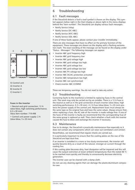
X A B C<br />
X) Control unit<br />
A) Inverter A<br />
B) Inverter B<br />
C) Inverter C<br />
Fuses in the inverter<br />
• Neutral and grid connection: 1 A<br />
(slow-blow, high switching performance,<br />
6.3 x 30 mm)<br />
Steca item number: 719.498<br />
• Control unit power supply: A<br />
(slow-blow, 5 x 0 mm)<br />
EN<br />
6 Troubleshooting<br />
6.1 Fault messages<br />
If the <strong>StecaGrid</strong> detects a fault a tool symbol is shown on the display. This symbol<br />
appears below right in the Start display or above right in the menu displays<br />
behind the "item number". The <strong>StecaGrid</strong> can display various fault messages:<br />
•<br />
•<br />
•<br />
•<br />
Notify Service (relay)<br />
Notify Service (DC-ABC)<br />
Notify Service (NTC-ABC)<br />
Notify Service (SDL ABC)<br />
If one of these faults appear, please contact your installer immediately.<br />
There are also messages that have no effect on the primary function of the<br />
equipment. These messages are shown on the display with a flashing exclamation<br />
mark. The exact wording of the message can be found on the display under<br />
"Status - Messages". The following messages can appear:<br />
• Inverter ABC grid frequency high<br />
• Inverter ABC grid frequency low<br />
• Inverter ABC grid voltage high<br />
• Inverter ABC grid voltage too high<br />
• Inverter ABC grid voltage low<br />
• Inverter ABC grid voltage too low<br />
• Inverter ABC PV voltage too high<br />
• Inverter ABC DC/AC protection activated<br />
• Inverter ABC temperature too high<br />
• Inverter ABC not synchronised<br />
• Check inverter ABC (COMM)<br />
These are temporary warnings. You do not need to take any action.<br />
6.2 Troubleshooting<br />
Correcting faults to the inverter(s) is limited to replacing fuses in the control<br />
unit. This work may only be carried out by an installer. There is a 1 A fuse in<br />
the neutral as well as in the grid connection of each inverter (slow-blow, high<br />
switching performance, 6.3 x 30 mm). A A fuse (slow-blow, 5 x 0 mm) protects<br />
the power supply of the control unit. Replacement fuses must always be<br />
the same type as the original fuse and have the same values. Always ensure that,<br />
when replacing a fuse, the AC side of the inverter is made voltage-free. If one of<br />
the fuses of the inverter is faulty we recommend that the corresponding fuse of<br />
the same group is replaced as well. Then check whether a fault with the inverter<br />
caused the fuse to blow and exchange the inverter if necessary.<br />
6.3 Maintenance<br />
Due to its design, the <strong>StecaGrid</strong> is practically maintenance-free especially as it<br />
does not contain any components which can wear out (ventilators and similar).<br />
Nevertheless, we recommend that regular checks are carried out.<br />
It is particularly important to ensure that the cooling plates on the rear of the<br />
<strong>StecaGrid</strong> are kept dust-free.<br />
If an inverter is installed in a more or less dusty environment, the inverter will<br />
quickly become dirty as a result of the natural, stronger air current through the<br />
cooling fins.<br />
If this cooling plate becomes dirty, heat dissipation will be impaired and this will<br />
cause the output restriction at lower ambient temperatures than the stated 40 °C<br />
to be reached more quickly and thereby to unnecessarily decrease electricity<br />
generation.<br />
The inverter case can be cleaned with a damp cloth.<br />
Do not use any cleaning agents that can damage the plastic/aluminium composite<br />
case.<br />
7 6.439 | 10.04<br />
45
![SCHOTT PROTECT POLY 175-185 data sheet_D[...] - bk solar](https://img.yumpu.com/1309848/1/186x260/schott-protect-poly-175-185-data-sheet-d-bk-solar.jpg?quality=85)