StecaGrid 000+ Master/Slave StecaGrid 000+ Maître/Esclave - Axun
StecaGrid 000+ Master/Slave StecaGrid 000+ Maître/Esclave - Axun
StecaGrid 000+ Master/Slave StecaGrid 000+ Maître/Esclave - Axun

Create successful ePaper yourself
Turn your PDF publications into a flip-book with our unique Google optimized e-Paper software.
EN<br />
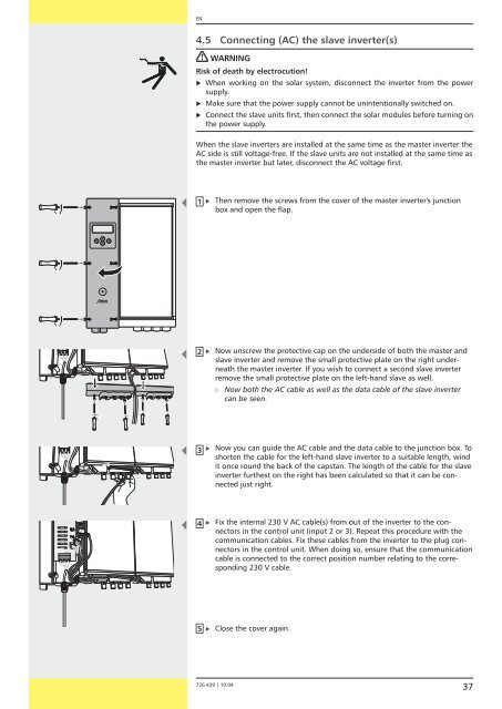
4.5 Connecting (AC) the slave inverter(s)<br />
WARNING<br />
Risk of death by electrocution!<br />
�<br />
�<br />
�<br />
When working on the solar system, disconnect the inverter from the power<br />
supply.<br />
Make sure that the power supply cannot be unintentionally switched on.<br />
Connect the slave units first, then connect the solar modules before turning on<br />
the power supply.<br />
When the slave inverters are installed at the same time as the master inverter the<br />
AC side is still voltage-free. If the slave units are not installed at the same time as<br />
the master inverter but later, disconnect the AC voltage first.<br />
1<br />
2<br />
3<br />
4<br />
5<br />
�<br />
�<br />
�<br />
�<br />
�<br />
Then remove the screws from the cover of the master inverter's junction<br />
box and open the flap.<br />
Now unscrew the protective cap on the underside of both the master and<br />
slave inverter and remove the small protective plate on the right underneath<br />
the master inverter. If you wish to connect a second slave inverter<br />
remove the small protective plate on the left-hand slave as well.<br />
�<br />
7 6.439 | 10.04<br />
Now both the AC cable as well as the data cable of the slave inverter<br />
can be seen.<br />
Now you can guide the AC cable and the data cable to the junction box. To<br />
shorten the cable for the left-hand slave inverter to a suitable length, wind<br />
it once round the back of the capstan. The length of the cable for the slave<br />
inverter furthest on the right has been calculated so that it can be connected<br />
just right.<br />
Fix the internal 30 V AC cable(s) from out of the inverter to the connectors<br />
in the control unit (input or 3). Repeat this procedure with the<br />
communication cables. Fix these cables from the inverter to the plug connectors<br />
in the control unit. When doing so, ensure that the communication<br />
cable is connected to the correct position number relating to the corresponding<br />
30 V cable.<br />
Close the cover again.<br />
37


![SCHOTT PROTECT POLY 175-185 data sheet_D[...] - bk solar](https://img.yumpu.com/1309848/1/186x260/schott-protect-poly-175-185-data-sheet-d-bk-solar.jpg?quality=85)