StecaGrid 000+ Master/Slave StecaGrid 000+ Maître/Esclave - Axun
StecaGrid 000+ Master/Slave StecaGrid 000+ Maître/Esclave - Axun
StecaGrid 000+ Master/Slave StecaGrid 000+ Maître/Esclave - Axun

Create successful ePaper yourself
Turn your PDF publications into a flip-book with our unique Google optimized e-Paper software.
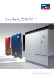
PHOTOVOLTAIK - PHOTOVOLTAIC - PHOTOVOLTAIQUE - FOTOVOLTAICA<br />
Installations- und Bedienungsanleitung<br />
Installation and operating instructions<br />
Instructions d'installation et de service<br />
<strong>StecaGrid</strong> <strong>000+</strong> <strong>Master</strong>/<strong>Slave</strong><br />
<strong>StecaGrid</strong> <strong>000+</strong> <strong>Maître</strong>/<strong>Esclave</strong><br />
DE / EN / FR<br />
7 6.439 | Z04 | 10.04
Inhaltsverzeichnis<br />
Sicherheit ...................................................................................................... 3<br />
Einleitung ..................................................................................................... 3<br />
1 Zu dieser Anleitung...................................................................................4<br />
1.1 Gültigkeit ............................................................................................. 4<br />
1. Adressaten ........................................................................................... 4<br />
1.3 Symbolerklärung .................................................................................. 4<br />
2 Sicherheit ..................................................................................................4<br />
.1 Bestimmungsgemäße Verwendung ..................................................... 4<br />
. Nicht zulässige Verwendung ................................................................ 5<br />
.3 Gefahren bei Montage und Inbetriebnahme ........................................ 5<br />
.4 Gefahren im Betrieb ............................................................................. 5<br />
.5 Haftungsausschluss .............................................................................. 5<br />
3 Technischer Aufbau des <strong>StecaGrid</strong>............................................................6<br />
3.1 Allgemein............................................................................................. 6<br />
3. <strong>Master</strong><strong>Slave</strong>-Prinzip .............................................................................. 6<br />
3.3 Kühlung ............................................................................................... 6<br />
3.4 Sicherheitsaspekte & geltende Normen ................................................ 7<br />
3.5 Datenkommunikation .......................................................................... 7<br />
4 Installation ................................................................................................8<br />
4.1 Allgemeine Voraussetzungen für die Installation ................................. 8<br />
4. Hinweise zur Montage ......................................................................... 8<br />
4.3 Montage .............................................................................................. 9<br />
4.4 Anschließen (AC) des <strong>Master</strong>-Wechselrichters .................................... 10<br />
4.5 Anschließen (AC) des (der) <strong>Slave</strong>-Wechselrichter(s) ............................ 11<br />
4.6 Anschließen (DC) von <strong>Master</strong> und <strong>Slave</strong>s ........................................... 1<br />
4.7 Anschließen des Kommunikationsmoduls (<strong>StecaGrid</strong> Connect) .......... 13<br />
4.8 Erstmaliges Einschalten der Netzspannung ........................................ 13<br />
4.9 Navigation auf dem Display ............................................................... 14<br />
5 Betrieb des <strong>StecaGrid</strong> .............................................................................15<br />
5.1 Betriebs- und Störungsanzeige mittels einer LED ............................... 15<br />
6 Störungsbeseitigung...............................................................................19<br />
6.1 Fehlermeldungen ............................................................................... 19<br />
6. Störungsbeseitigung .......................................................................... 19<br />
6.3 Wartung ............................................................................................ 19<br />
7 Technische Daten ....................................................................................20<br />
8 Gewährleistungs- und Garantiebestimmungen .......................................... 21<br />
9 Kontakt ...................................................................................................22<br />
Anhang..........................................................................................................22<br />
Glossar ........................................................................................................<br />
Notizen ....................................................................................................... 4<br />
Installationsanleitung (Kurzversion) .............................................................25<br />
Montage ..................................................................................................... 5<br />
Inbetriebnahme .......................................................................................... 6<br />
Ländertabelle .............................................................................................. 6<br />
DE<br />
7 6.439 | 10.04
DE<br />
Sicherheit<br />
WARNUNG<br />
Lebensgefahr durch Stromschlag!<br />
�<br />
Der Anschluss an das Stromnetz darf nur durch ausgebildetes Fachpersonal<br />
nach den Vorschriften des örtlichen Energieversorgungsunternehmens vorgenommen<br />
werden.<br />
Einleitung<br />
Durch die Nutzung erneuerbarer Energieträger kann ein wesentlicher Beitrag<br />
zum Umweltschutz geleistet werden, indem die Belastung der Erdatmosphäre<br />
durch CO und andere schädliche Gase, die bei der Umwandlung fossiler Energieträger<br />
anfallen, verringert wird. Eine dieser erneuerbaren Energiequellen ist<br />
die Sonne.<br />
Die Sonnenenergie wird mit Hilfe eines sogenannten PV-Systems umgewandelt<br />
(PV steht für Photovoltaik; eine Erläuterung hierzu finden Sie im Glossar der<br />
Fachausdrücke hinten in diesem Handbuch). Ein derartiges PV-System enthält<br />
unter anderem einen Wechselrichter. Der Wechselrichter setzt den durch die<br />
Solarmodule erzeugten Gleichstrom in Wechselstrom um, der direkt in das<br />
öffentliche Stromnetz eingespeist werden kann. Der <strong>StecaGrid</strong> wurde für so<br />
genannte “netzgekoppelte Systeme” entworfen. Bei diesen Systemen wird der<br />
Wechselrichter parallel an das öffentliche Stromnetz angeschlossen.<br />
Das Solarstromsystem speist den netzkonformen Wechselstrom über einen zusätzlichen<br />
Einspeisezähler (Basis für die Einspeisevergütung) direkt in das Verbundnetz<br />
des VNB (Verbundnetzbetreibers) ein und steht somit allen am Netz<br />
angeschlossenen Verbrauchern zur Verfügung. Die von den Stromverbrauchern<br />
bezogene Energie wird wie gewohnt über den vorhandenen Bezugszähler<br />
abgerechnet.<br />
In dem Wechselrichter <strong>StecaGrid</strong> kommt modernste Hochfrequenztechnik zum<br />
Einsatz, so dass ein sehr hoher Wirkungsgrad erreicht wird. Der Wechselrichter<br />
nutzt das <strong>Master</strong>/<strong>Slave</strong>-Prinzip. Bei diesem Prinzip werden einige Funktionen<br />
für mehrere Wechselrichter zentral geregelt, und zwar in dem sogenannten<br />
<strong>Master</strong>-Wechselrichter. Der <strong>Master</strong>-Wechselrichter kann bis zu zwei an ihn<br />
angeschlossene <strong>Slave</strong>-Wechselrichter steuern. Die Auslegung des Systems wird<br />
dadurch flexibler. Zudem werden die Kosten durch den Einsatz der <strong>Slave</strong>-Wechselrichter<br />
gesenkt.<br />
Der <strong>Master</strong> enthält u.a. die zentrale Regeleinheit, einen Datalogger und ein<br />
Display. Über dieses Display erhält man schnell eine Übersicht über die Funktion<br />
des Systems. Der <strong>StecaGrid</strong> <strong>Master</strong>-Wechselrichter kann u.a. um eine<br />
optionale Netzwerkkarte <strong>StecaGrid</strong> Connect erweitert werden. Weitere Informationen<br />
über Kommunikationsverbindungen und anderes Zubehör finden Sie<br />
unter www.stecasolar.com. Selbstverständlich kann Ihnen auch Ihr Installateur<br />
nähere Auskunft über die zur Verfügung stehenden Möglichkeiten geben.<br />
In der weiteren technischen Beschreibung werden dem Installateur und Benutzer<br />
technische Merkmale beschrieben, die für die Installation, die Funktion, die<br />
Bedienung und Benutzung des <strong>StecaGrid</strong> erforderlich sind.<br />
7 6.439 | 10.04<br />
3
1 Zu dieser Anleitung<br />
1.1 Gültigkeit<br />
Diese Anleitung beschreibt Installation, Inbetriebnahme, Funktion, Bedienung,<br />
Wartung und Demontage des Wechselrichters für netzgekoppelte Photovoltaikanlagen.<br />
Für die Montage der übrigen Komponenten, z. B. der Photovoltaikmodule, der<br />
DC- bzw. AC-Verkabelung und weiterer Zubehörgeräte, sind die entsprechenden<br />
Montageanleitungen der jeweiligen Hersteller zu beachten.<br />
<strong>StecaGrid</strong> <strong>000+</strong> D <strong>Master</strong>-M: <strong>Master</strong> mit ENS (Deutschland), Multi-Contact-<br />
Konnektoren (MC4, Sunline ).<br />
<strong>StecaGrid</strong> <strong>000+</strong> 0 <strong>Master</strong>-M: <strong>Master</strong> ohne ENS, Multi-Contact-Konnektoren<br />
(MC4, Sunline ).<br />
<strong>StecaGrid</strong> <strong>000+</strong> <strong>Slave</strong>-M: <strong>Slave</strong>, Multi-Contact-Konnektoren (MC4, Sunline ).<br />
1.2 Adressaten<br />
Installation, Inbetriebnahme, Bedienung, Wartung und Demontage des Wechselrichters<br />
dürfen nur durch ausgebildetes Fachpersonal unter Beachtung der vor Ort<br />
geltenden Installationsvorschriften erfolgen. Das Fachpersonal muss mit dieser<br />
Bedienungsanleitung vertraut sein und die Anweisungen befolgen.<br />
Der Endkunde darf nur die Bedienfunktionen ausführen.<br />
1.3 Symbolerklärung<br />
1.3.1 Aufbau von Warnhinweisen<br />
SIGNALWORT<br />
Art, Quelle und Folgen der Gefahr!<br />
� Maßnahmen zur Vermeidung der Gefahr<br />
1.3.2 Gefahrenstufen in Warnhinweisen<br />
Gefahrenstufe Eintretens-Wahrscheinlichkeit Folgen bei Nichtbeachtung<br />
GEFAHR<br />
Unmittelbar drohende Gefahr Tod, schwere Körperverletzung<br />
WARNUNG<br />
Mögliche drohende Gefahr Tod, schwere Körperverletzung<br />
VORSICHT<br />
Mögliche drohende Gefahr Leichte Körperverletzung<br />
VORSICHT Mögliche drohende Gefahr Sachschaden<br />
1.3.3 Hinweise<br />
HINWEIS<br />
Hinweis zum leichteren bzw. sicheren Arbeiten.<br />
� Maßnahme zum leichteren bzw. sicheren Arbeiten<br />
1.3.4 Sonstige Symbole und Kennzeichnungen<br />
Symbol Bedeutung<br />
� Handlungsaufforderung<br />
� Resultat einer Handlung<br />
- Beschreibung einer Aktion<br />
• Aufzählung<br />
Hervorhebung Hervorhebung<br />
2 Sicherheit<br />
2.1 Bestimmungsgemäße Verwendung<br />
Der Wechselrichter darf nur in netzgekoppelten Photovoltaikanlagen innerhalb<br />
des zulässigen Leistungsbereichs und der zulässigen Umgebungsbedingungen<br />
verwendet werden. Bei nichtbestimmungsgemäßer Verwendung können Schutzfunktionen<br />
beeinträchtigt werden.<br />
4<br />
DE<br />
7 6.439 | 10.04
DE<br />
2.2 Nicht zulässige Verwendung<br />
In folgender Umgebung darf der Wechselrichter nicht betrieben werden:<br />
•<br />
•<br />
•<br />
in zu warmen Räumen<br />
in staubigen Räumen<br />
in Räumen, in denen leicht entzündliche Gasgemische entstehen können<br />
2.3 Gefahren bei Montage und Inbetriebnahme<br />
Folgende Gefahren bestehen während Montage / Inbetriebnahme des Wechselrichters<br />
und im Betrieb (bei Montagefehlern):<br />
•<br />
•<br />
•<br />
•<br />
•<br />
•<br />
•<br />
•<br />
•<br />
•<br />
•<br />
•<br />
•<br />
Lebensgefahr durch Stromschlag<br />
Brandgefahr durch Kurzschluss<br />
Beeinträchtigte Feuersicherheit des Gebäudes durch fehlerhafte Leitungsführung<br />
Beschädigung des Wechselrichters und angeschlossener Geräte bzw. Komponenten<br />
bei unzulässigen Umgebungsbedingungen, unangemessener Energieversorgung<br />
(sowohl auf Gleichstrom- als auch auf der Wechselstromseite)<br />
sowie Anschluss nicht erlaubter Geräte bzw. Komponenten<br />
Es gelten daher alle Sicherheitsvorschriften für das Arbeiten am Netz. Das<br />
Öffnen des Wechselrichters ist nicht erlaubt.<br />
Bei der Leitungsführung darauf achten, dass feuersicherheitstechnische bauliche<br />
Maßnahmen nicht beeinträchtigt werden.<br />
Sicherstellen, dass die zulässigen Umgebungsbedingungen am Montageort<br />
nicht überschritten werden.<br />
Vom Werk angebrachte Schilder und Kennzeichnungen nicht verändern, entfernen<br />
oder unkenntlich machen.<br />
Vor dem Anschließen des Gerätes sicherstellen, dass die Energieversorgung<br />
(sowohl DC als auch AC) mit den angegebenen Werten auf dem Typenschild<br />
übereinstimmt.<br />
Sicherstellen, dass Geräte bzw. Komponenten, die an den Wechselrichter angeschlossen<br />
werden, mit den technischen Daten des Wechselrichters übereinstimmen.<br />
Gerät gegen unbeabsichtigte Inbetriebnahme sichern.<br />
Alle Arbeiten zur Montage des Wechselrichters nur bei freigeschaltetem Netz<br />
und freigeschaltetem Photovoltaikgenerator durchführen.<br />
Den Wechselrichter gegen Überlastung und Kurzschluss schützen.<br />
2.4 Gefahren im Betrieb<br />
WARNUNG<br />
Gefahr durch Hitze!<br />
�<br />
Die Oberflächentemperatur des Aluminiumdeckels kann über 70 °C überschreiten.<br />
2.5 Haftungsausschluss<br />
Sowohl das Einhalten dieser Anleitung als auch die Bedingungen und Methoden<br />
bei Installation, Betrieb, Verwendung und Wartung des Wechselrichters können<br />
vom Hersteller nicht überwacht werden. Eine unsachgemäße Ausführung der<br />
Installation kann zu Sachschäden führen und in Folge Personen gefährden.<br />
Daher übernehmen wir keinerlei Verantwortung und Haftung für Verluste, Schäden<br />
oder Kosten, die sich aus fehlerhafter Installation, unsachgemäßem Betrieb<br />
sowie falscher Verwendung und Wartung ergeben oder in irgendeiner Weise<br />
damit zusammenhängen.<br />
Ebenso übernehmen wir keine Verantwortung für patentrechtliche Verletzungen<br />
oder Verletzung anderer Rechte Dritter, die aus der Verwendung dieses Wechselrichters<br />
resultieren.<br />
Der Hersteller behält sich das Recht vor, ohne vorherige Mitteilung Änderungen<br />
bezüglich des Produkts, der technischen Daten oder der Montage- und Betriebsanleitung<br />
vorzunehmen.<br />
�<br />
Wenn erkennbar ist, dass ein gefahrloser Betrieb nicht mehr möglich ist<br />
(z. B. bei sichtbaren Beschädigungen), Gerät sofort vom Netz und Photovoltaikgenerator<br />
trennen.<br />
7 6.439 | 10.04<br />
5
3 Technischer Aufbau des <strong>StecaGrid</strong><br />
3.1 Allgemein<br />
Der <strong>StecaGrid</strong> ist ein Wechselrichter, der zur galvanischen Trennung von Solarmodulen<br />
und Netz einen Transformator nutzt. Der Wechselrichter wurde so konzipiert,<br />
dass er problemlos im Freien installiert werden kann (IP65).<br />
Der <strong>StecaGrid</strong> wird durch Mikrocontroller gesteuert. Die Mikrocontroller stellen<br />
die Spannung der Solarmodule so ein, dass die Solarmodule ihre maximale<br />
Leistung bereitstellen (Maximum Power Point Tracking). Beide Eingänge verfügen<br />
über einen eigenen MPP-Tracker, so dass Sie Ihr System flexibel entwerfen<br />
können. Sie können zum Beispiel ohne Fehlanpassung und damit ohne Ertragseinbuße<br />
die Module mit südöstlicher Ausrichtung an Eingang 1 anschließen<br />
und die Module mit südwestlicher Ausrichtung an Eingang . Außerdem ist es<br />
möglich, Module des Typs A an Eingang 1 anzuschließen und Module des Typs B<br />
an Eingang , ohne dass es zu einer Fehlanpassung kommt.<br />
Der Eingangsspannungsbereich wurde so gewählt, dass der Nennspannungsbereich<br />
der PV-Module von 80 V - 410 V abgedeckt wird (Leerlaufspannung max.<br />
450 V). Der maximale Eingangsstrom, den der Wechselrichter verarbeiten kann,<br />
beträgt 8 A pro Eingang. Wenn die beiden Eingänge des Wechselrichters parallel<br />
geschaltet werden, kann der Wechselrichter Ströme bis 16 A verarbeiten. Der<br />
MPP-Tracker sorgt dafür, dass die Eingangsströme den maximal zulässigen Strom<br />
niemals überschreiten.<br />
Der Wechselrichter minimiert die Nutzung der Elektronik und den Stromverbrauch<br />
bei Nacht, indem er sich auf Sleep-Modus schaltet. Der Wechselrichter ist<br />
gegen Inselbetrieb geschützt.<br />
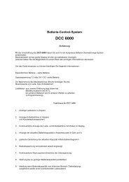
3.2 <strong>Master</strong><strong>Slave</strong>-Prinzip<br />
Der <strong>StecaGrid</strong> arbeitet nach dem <strong>Master</strong><strong>Slave</strong>-Prinzip. Bei diesem Prinzip werden<br />
mehrere Funktionen in dem <strong>Master</strong> (Wechselrichter A in der Abbildung) zusammengefasst.<br />
Die Wechselrichter ohne diese Funktionen werden als <strong>Slave</strong>-Wechselrichter bezeichnet<br />
(Wechselrichter B und C in der Abbildung). Die Ländereinstellung erfolgt<br />
über den <strong>Master</strong>.<br />
Die eventuelle ENS-Funktion wird über den <strong>Master</strong> für alle Wechselrichter geregelt.<br />
Außerdem speichert der <strong>Master</strong> u.a. die Daten des <strong>Master</strong>-Wechselrichters<br />
und der <strong>Slave</strong>-Wechselrichter. Dank dieser zentralen Zusammenfassung der Funktionen<br />
können <strong>Slave</strong>-Wechselrichter kostengünstiger und kompakter ausgeführt<br />
werden. An jeden <strong>StecaGrid</strong> <strong>Master</strong>-Wechselrichter können <strong>StecaGrid</strong> <strong>Slave</strong>-<br />
Wechselrichter angeschlossen werden. Jeder <strong>StecaGrid</strong> <strong>Master</strong>-Wechselrichtertyp<br />
kann mit jedem <strong>StecaGrid</strong> <strong>Slave</strong>-Wechselrichtertyp kombiniert werden (max. sind<br />
zwei <strong>Slave</strong>s pro <strong>Master</strong> möglich). Die Kombination von <strong>Master</strong>- und <strong>Slave</strong>geräten<br />
ermöglicht bei der Auslegung maximale Flexibilität: Systemgrößen zwischen<br />
1600 Wp und 7000 Wp sind durch <strong>Master</strong><strong>Slave</strong>-Kombinationen möglich.* Für<br />
Systemgrößen von mehr als 7000 Wp können mehrere <strong>Master</strong><strong>Slave</strong>-Kombinationen<br />
eingesetzt werden.<br />
* bei einem Dimensionierungsverhältnis von 0,8 bis 1, 5 und der Annahme, dass die Systemspannung und der Systemstrom<br />
im Arbeitsbereich des Wechselrichters liegen.<br />
Das Auslegungsprogramm <strong>StecaGrid</strong> Configurator finden Sie unter<br />
www.stecasolar.com.<br />
3.3 Kühlung<br />
Der Wechselrichter gibt seine Wärme über einen Kühlkörper ab. Dank der großen<br />
Oberfläche des Kühlprofils kann der Wechselrichter bei Umgebungstemperaturen<br />
von – 5 °C bis +60 °C arbeiten.<br />
6<br />
WARNUNG<br />
Gefahr durch Hitze!<br />
�<br />
Die Oberflächentemperatur des Aluminiumdeckels kann 70 °C überschreiten.<br />
Eine interne Temperaturregelung verhindert überhöhte Innentemperaturen.<br />
Wenn die Temperatur der Umgebung die (Derating-)Grenze überschreitet, passt<br />
sich der Höchstwert der Leistungsaufnahme aus den PV-Modulen automatisch<br />
an die herrschenden Temperaturen an. Auf diese Weise wird die Wärmeabgabe<br />
des Wechselrichters verringert und eine zu hohe Betriebstemperatur verhindert.<br />
DE<br />
7 6.439 | 10.04<br />
<strong>Master</strong><br />
X A B C<br />
X) Steuereinheit<br />
A) Wechselrichter A<br />
B) Wechselrichter B<br />
C) Wechselrichter C<br />
<strong>Slave</strong> <strong>Slave</strong>
DE<br />
Bei Umgebungstemperaturen über +40 °C kann die maximale Leistung begrenzt<br />
werden. Die <strong>StecaGrid</strong> Wechselrichter verzichten für die Kühlung auf einen Lüfter<br />
und sind dadurch besonders wartungsarm.<br />
3.4 Sicherheitsaspekte & geltende Normen<br />
Zur zusätzlichen Sicherheit sind das Netz und die Solarmodule galvanisch voneinander<br />
getrennt. Außerdem sind sowohl die Phase als auch der Neutralleiter jedes<br />
Wechselrichters mit einer Sicherung ausgestattet. Diese Sicherungen sind sowohl<br />
für den <strong>Master</strong> als auch für den <strong>Slave</strong> an einer gut zugänglichen Stelle in der<br />
Steuereinheit des <strong>Master</strong>s angeordnet. Der Wechselrichter erfüllt die Anforderungen<br />
aller geltenden Normen in Bezug auf die elektromagnetische Verträglichkeit<br />
(EMV) und die Sicherheitstechnik. Der <strong>StecaGrid</strong> entspricht darüber hinaus<br />
den Richtlinien für den Betrieb von energieerzeugenden Anlagen parallel zum<br />
Niederspannungsnetz des regionalen Stromversorgungsunternehmens. Das CE-<br />
Zeichen ist auf dem Typenschild des Wechselrichters zu finden.<br />
Der Wechselrichter kontrolliert die Netzqualität, indem er sowohl die Netzspannung<br />
und die Netzfrequenz als auch (u.a. für Deutschland zutreffend) die<br />
Netzimpedanz misst. Bei Netzstörungen wird sich der Wechselrichter automatisch<br />
vom Netz abschalten. Bei welchen Werten sich der Wechselrichter selbst<br />
vom Netz abschaltet, ist je nach Land unterschiedlich; die nachstehende Tabelle<br />
enthält eine entsprechende Übersicht der Vorgaben der Länder:<br />
7 6.439 | 10.04<br />
Netzspannung<br />
(Abschaltwert)<br />
Default -10 % / + 6 %<br />
der Nennspannung (0,1 s)<br />
3100<br />
Niederlande<br />
3200<br />
Belgien<br />
3300<br />
Frankreich<br />
3400<br />
Spanien<br />
4400<br />
Großbritannien<br />
4900<br />
Deutschland<br />
4901<br />
Deutschland<br />
-10 % / +10 %<br />
der Nennspannung (0,1 s)<br />
- 0 % / +6 %<br />
der Nennspannung (0, s)<br />
- 0 % / +15 %<br />
der Nennspannung (0, s)<br />
-15 % / +10 %<br />
der Nennspannung (0, s)<br />
-10 % / +15 %<br />
der Nennspannung (1,5 s)<br />
- 0 % / +15 %<br />
der Nennspannung (0, s)<br />
- 0 % / +15 %<br />
der Nennspannung (0, s)<br />
Netzfrequenz<br />
(Abschaltwert)<br />
+/- 0, Hz<br />
der Nennfequenz (0, s)<br />
+/- Hz der<br />
Nennfequenz ( s)<br />
+/- 0, Hz<br />
der Nennfequenz (0, s)<br />
- ,5 / + 0, Hz<br />
der Nennfequenz (0, s)<br />
+/- 1 Hz<br />
der Nennfequenz (0, s)<br />
+/- 1 Hz<br />
der Nennfequenz (0,5 s)<br />
- ,5 / + 0, Hz<br />
der Nennfequenz (0, s)<br />
- ,5 / + 0, Hz<br />
der Nennfequenz (0, s)<br />
Netzimpedanz-<br />
Überwachung<br />
ja, nach<br />
VDE 01 6-1-1*<br />
Wiederzuschaltzeit<br />
180 s<br />
Nicht zutreffend 0 s<br />
ja, nach<br />
VDE 01 6-1-1*<br />
30 s<br />
Nicht zutreffend 30 s<br />
Nicht zutreffend 180 s<br />
Nicht zutreffend 180 s<br />
ja, nach<br />
VDE 01 6-1-1*<br />
30 s<br />
Nicht zutreffend 30 s<br />
Mit der Installation des Wechselrichters muss das Land gewählt werden, in dem<br />
der Wechselrichter aufgestellt wird. In Abschnitt ‘Erstmaliges Einschalten der<br />
Netzspannung’ wird erläutert, wie die korrekte Ländereinstellung ausgewählt<br />
werden kann.<br />
Wenn Ihr Land in der aktuellen Länderübersichtsliste fehlt, können Sie gegebenenfalls<br />
die Einstellungen eines anderen Landes verwenden. Bitte fragen Sie in<br />
diesem Fall bei unserer Hotline nach. Sie erreichen sie unter der Nummer:<br />
+49 (0) 700 783 4743.<br />
* nur erhältlich beim Typ <strong>StecaGrid</strong> <strong>000+</strong> D <strong>Master</strong>-M.<br />
3.5 Datenkommunikation<br />
Um auf einfache Weise einen Überblick über die Funktion des Systems zu erhalten,<br />
werden innerhalb des Wechselrichters unter anderem Spannung, Strom und<br />
Leistung des Solargenerators sowie die Netzfrequenz und die Netzspannung<br />
gemessen. Außerdem werden die Energieerträge sowohl des <strong>Master</strong>s als auch<br />
der <strong>Slave</strong>s auf Tages-, Monats- und Jahresbasis gespeichert.<br />
Über das Display können sowohl diese Messwerte als auch die Betriebszustände<br />
des <strong>StecaGrid</strong> abgelesen werden. Optional ist es möglich, die Daten des <strong>StecaGrid</strong><br />
mit Hilfe von Software (<strong>StecaGrid</strong> Connect User) und einer Netzwerkkarte<br />
(<strong>StecaGrid</strong> Connect) herunterzuladen und mit einem PC zu verarbeiten. Wenn<br />
der Wechselrichter eine feste Internetverbindung hat, können die Daten mit<br />
dieser Karte und dem zugehörigen Passwort von jedem beliebigen Ort aus über<br />
einen Webbrowser eingesehen werden. Diese Funktionen machen eine vollständige,<br />
integrale Überwachung des Solarstromsystems möglich. Weitere Informationen<br />
u.a. zur Installation und Inbetriebnahme finden Sie in der separaten<br />
Bedienungsanleitung.<br />
7
4 Installation<br />
8<br />
WARNUNG<br />
Lebensgefahr durch Stromschlag!<br />
�<br />
�<br />
�<br />
�<br />
�<br />
�<br />
Der Anschluß des <strong>StecaGrid</strong> Wechselrichters an das Stromnetz darf nur durch<br />
qualifiziertes Fachpersonal entsprechend den Vorschriften der IEC-Norm 60364,<br />
der in Deutschland geltenden VDEW-Richtlinien/TAB 000 und den Vorschriften<br />
des örtlichen Energieversorgungsunternehmens vorgenommen werden.<br />
Beim Arbeiten an der Solaranlage Wechselrichter von der Stromversorgung<br />
trennen.<br />
Sicherstellen, dass Stromversorgung nicht unbeabsichtigt wieder eingeschaltet<br />
werden kann.<br />
DC-Verbindung zwischen Solarmodulen und von den Solarmodulen zum Wechselrichter<br />
nicht unterbrechen solange Strom fließt. Falls die DC-Verbindung<br />
unterbrochen werden muss, Wechselrichter immer zuerst vom Netz trennen.<br />
Kabel so verlegen, dass sich die Verbindung nicht versehentlich lösen kann.<br />
MC-Verbindung zusammendrücken bis Einrastung hörbar schließt<br />
4.1 Allgemeine Voraussetzungen für die Installation<br />
Bei Verwendung mehrerer Wechselrichter an einer Phase gilt in Deutschland<br />
eine maximale Anschlussleistung von 4,6 kVA. Bei höheren Leistungen ist eine<br />
Verteilung auf mehrere Phasen erforderlich. Bei Verteilung auf mehrere Phasen<br />
darf jedoch die Phasenungleichheit nicht mehr als 4,6 kVA betragen. Einzelheiten<br />
über die Anschlussbedingungen sind den nationalen und/oder regionalen Vorschriften<br />
zu entnehmen.<br />
In den Grundzügen bedeutet dies, dass jeder Wechselrichter bzw. jede Wechselrichter-Gruppe<br />
mittels eines Netzschalters/Netztrennschalters an eine eigene<br />
Sicherungsgruppe in der elektrischen Anlage angeschlossen werden muss. Dieser<br />
Netzschalter muss sich in demselben Raum befinden wie der Wechselrichter und<br />
eine ausreichende Schaltkapazität besitzen. Die Photovoltaik-Anlage muss dabei<br />
als Belastung des Stromnetzes betrachtet werden.<br />
Als Ausnahme davon gilt, wenn der/die Wechselrichter sich ebenfalls im Niederspannungs-Verteilerraum<br />
befindet/befinden; ein gesonderter Schalter ist dann nicht<br />
erforderlich, da der jeweilige Gruppenschalter diese Funktion übernehmen kann.<br />
Ferner ist in allen Cenelec-Ländern (Niederlande, Deutschland, Spanien, Italien,<br />
etc.) ein DC-Freischalter erforderlich.* Der Nennstrom muss so bemessen sein,<br />
dass die Summe aller Ströme (Kurzschlussströme der angeschlossenen Stränge)<br />
abgeschaltet werden kann. Wenn Sie möchten, können Sie diesen DC-Freischalter<br />
über Ihren Händler bei Steca beziehen. Die Nennspannung des DC-Freischalters<br />
muss min. 500 V betragen.<br />
Der Installateur hat darauf zu achten, dass alle geltenden Installationsvorschriften,<br />
nationalen Gesetze, Installationsnormen und Anschlusswerte des<br />
regionalen Stromversorgungsunternehmens eingehalten werden.<br />
* Weitere Informationen finden Sie in der IEC-Norm IEC60364-7-71 .<br />
Leitungsquerschnitt und Sicherung:<br />
P Nenn Querschnitt Sicherung<br />
2 kW 1,5 mm² B16<br />
4 kW ,5 mm² B 5<br />
6 kW 4 mm² B3<br />
4.2 Hinweise zur Montage<br />
VORSICHT<br />
Beschädigung des Wechselrichters!<br />
� Wechselrichter nicht montieren<br />
• in zu warmen Räumen<br />
• in staubigen Räumen<br />
• in Räumen, in denen leicht entzündliche Gasgemische entstehen können<br />
� Kabel der Solarmodule so kurz wie möglich halten.<br />
� Wechselrichter nicht an Installationsorten montieren, an denen er Vibrationen<br />
ausgesetzt ist.<br />
DE<br />
7 6.439 | 10.04
DE<br />
�<br />
�<br />
Luftstrom zur Kühlung der Wechselrichter nicht behindern. Zur Luftzirkulation<br />
um das Gerät herum muss ober- und unterhalb des Geräts ein Raum von mindestens<br />
0 cm frei bleiben.<br />
Die elektrischen Verbindungen müssen in der korrekten Reihenfolge hergestellt<br />
werden:<br />
7 6.439 | 10.04<br />
1. Verbindung zum Netz herstellen<br />
. PV-Generator anschließen<br />
3. Netzleitungs-Sicherheitsschalter schließen<br />
Dank seiner Schutzart (IP65) kann der <strong>StecaGrid</strong> Wechselrichter an zahlreichen<br />
Orten montiert werden. Bei der Installation müssen allerdings einige Punkte<br />
beachtet werden, die im Folgenden aufgeführt sind.<br />
•<br />
Da das Gerät ein leichtes Brummen/Rauschen abgeben kann (< 3 dBA), sollte<br />
es nicht in Wohnräumen installiert werden.<br />
• Der Wechselrichter darf nicht in Ställen mit aktiver Tierhaltung installiert werden<br />
(Gefährdung der Tiere bzw. Gefährdung des elektrischen Systems durch<br />
die Tiere und durch erhöhte Staubentwicklung, Kabelbeschädigungen durch<br />
Ammoniak, etc.).<br />
• Die Kombination von 1 <strong>Master</strong>-Einheit und <strong>Slave</strong>-Einheiten kann hohe Ströme<br />
erzeugen. Passen Sie den Anschluss entsprechend an. Es empfiehlt sich,<br />
bei der Installation von 1 <strong>Master</strong>-Einheit den Anschluss für eine eventuelle<br />
Erweiterung um <strong>Slave</strong>-Einheiten vorzubereiten.<br />
• Die LED und das Display müssen ablesbar bleiben (Ablesewinkel).<br />
• Die Umgebungstemperatur muss im Bereich von – 5 °C bis 60 °C<br />
(besser 40 °C) bleiben.<br />
• Eine direkte Bestrahlung durch die Sonne muss vermieden werden. Erforderlichenfalls<br />
muss das Gerät gegen unmittelbare Sonnenstrahlung geschützt<br />
werden, indem vor und über dem Gerät eine gesonderte Abschirmungskonstruktion<br />
angebracht wird.<br />
• Es muss für ausreichende Lüftung gesorgt werden.<br />
• Im nächsten Abschnitt wird die Einbauposition des Wechselrichters beschrieben.<br />
Diese Einbauposition muss eingehalten werden.<br />
Die letzten 4 Punkte sind wichtig, um die Wahrscheinlichkeit einer Leistungsherabsetzung<br />
(Derating) zu minimieren. Werden diese Punkte nicht berücksichtigt,<br />
kann dies einen reduzierten Ertrag zur Folge haben.<br />
4.3 Montage<br />
Der <strong>StecaGrid</strong> ist für die Montage in vertikaler Position (stehend) vorgesehen.<br />
Die Abweichung aus der Lotrechten darf wegen der Gefahr einer Störung des<br />
Kühlsystems nicht mehr als +/- 15° betragen. Von der Montage in horizontaler<br />
Position (liegend) wird daher abgeraten.<br />
Der Wechselrichter ist mit einer (separaten) Montage-/Befestigungsplatte versehen.<br />
Jede Platte enthält zwei Verbindungshaken, die benutzt werden können,<br />
um eine nachfolgende Montageplatte exakt anzuschließen. Jede Montageplatte<br />
ist außerdem mit nach vorne hervorstehenden Haken versehen, an denen der<br />
Wechselrichter aufgehängt wird.<br />
Wählen Sie zur Montage des <strong>StecaGrid</strong> einen flachen, nicht leicht entflammbaren<br />
Hintergrund, z.B. eine Beton- oder Steinwand.<br />
1<br />
�<br />
�<br />
�<br />
�<br />
Befestigen Sie zunächst die Montageplatte mit Hilfe von 4 Schrauben (ø 5<br />
mm, nicht mitgeliefert). Berücksichtigen Sie dabei die Breite des Anschlusskastens<br />
des <strong>Master</strong>s; dieser Kasten steht links 1 ,5 cm hervor. Zusätzlich<br />
müssen ca. 3 cm Platz gelassen werden, damit der Deckel des Anschlusskastens<br />
geöffnet werden kann. Für jede <strong>Slave</strong>-Einheit, die mit dem <strong>Master</strong><br />
verbunden wird (max. ; die <strong>Slave</strong>-Einheiten werden rechts vom <strong>Master</strong><br />
aufgehängt), muss eine zusätzliche Montageplatte vorgesehen werden. Die<br />
Montageplatten sind mit Hilfe der Verbindungshaken exakt miteinander zu<br />
koppeln.<br />
9
2<br />
3<br />
10<br />
Anschließend kann der <strong>Master</strong>-Wechselrichter aufgehängt werden. Lassen<br />
Sie den Wechselrichter von oben auf die nach vorne hervorstehenden<br />
Haken gleiten. Achten Sie darauf, dass die Verriegelung über die Kühlplattenrippe<br />
fällt. Damit ist der Wechselrichter gegen ein Herunterfallen, z. B.<br />
durch unbeabsichtigtes Anheben, gesichert.<br />
Die am weitesten rechts gelegene Kühlrippe muss über den hochragenden<br />
Rand der Befestigungsplatte fallen. Auf dieselbe Weise können die eventuell<br />
vorhandenen <strong>Slave</strong>-Wechselrichter an den entsprechenden Montageplatten<br />
aufgehängt werden.<br />
4.4 Anschließen (AC) des <strong>Master</strong>-Wechselrichters<br />
WARNUNG<br />
Lebensgefahr durch Stromschlag!<br />
�<br />
�<br />
�<br />
�<br />
1<br />
�<br />
�<br />
Beim Arbeiten an der Solaranlage Wechselrichter von der Stromversorgung<br />
trennen.<br />
Sicherstellen, dass Stromversorgung nicht unbeabsichtigt wieder eingeschaltet<br />
werden kann.<br />
Schließen Sie zuerst eine gesonderte Gruppe an und sorgen Sie dafür, dass<br />
diese Gruppe spannungsfrei ist.<br />
Schließen Sie erst die eventuellen <strong>Slave</strong>-Einheiten und danach die Solarmodule<br />
an bevor Sie die Netzspannung einschalten.<br />
�<br />
Schrauben Sie den Deckel von der Steuereinheit des <strong>Master</strong>-Wechselrichters<br />
ab.<br />
DE<br />
7 6.439 | 10.04
min. 15 cm<br />
DE<br />
2<br />
3<br />
Das Netzkabel (AC Output - Wechselspannung- Ausgang) wird über die<br />
mit einer Überwurfmutter versehene Kabeldurchführung an die 3 WAGO<br />
Federzugklemmen angeschlossen. Das Aderende ist mindestens auf 8 mm<br />
abzuisolieren. Wird ein flexibles Anschlusskabel verwendet, so muss eine<br />
Aderendhülse aufgecrimpt werden. Das Aderende ist ordnungsgemäß in<br />
die geöffnete WAGO-Klemme einzuschieben und anschließend auf festen<br />
Sitz zu überprüfen. Die Führung des Netzkabels muss wie in nebenstehender<br />
Skizze dargestellt, erfolgen.<br />
Aus Gründen der Transportsicherheit ist die Kabelverschraubung dem Gerät<br />
beigelegt und muss vor einführen des Kabels montiert werden.<br />
Achten Sie darauf, dass Phasen-, Null- und Erde-Kabel in der richtigen<br />
Position angeschlossen werden [Aufdruck: Line-Neutral-PE]. Ziehen Sie die<br />
Überwurfmutter gut (handfest) an. Dadurch ist die Zugentlastung des Kabels<br />
ausreichend gewährleistet. Bei unsachgemäßer Benutzung von Werkzeugen<br />
ist eine Beschädigung der Überwurfmutter nicht ausgeschlossen.<br />
4.5 Anschließen (AC) des (der) <strong>Slave</strong>-Wechselrichter(s)<br />
WARNUNG<br />
Lebensgefahr durch Stromschlag!<br />
�<br />
�<br />
�<br />
Beim Arbeiten an der Solaranlage Wechselrichter von der Stromversorgung<br />
trennen.<br />
Sicherstellen, dass Stromversorgung nicht unbeabsichtigt wieder eingeschaltet<br />
werden kann.<br />
Schließen Sie erst die <strong>Slave</strong>-Einheiten und danach die Solarmodule an bevor Sie<br />
die Netzspannung einschalten.<br />
Wenn die <strong>Slave</strong>-Wechselrichter gleichzeitig mit dem <strong>Master</strong>-Wechselrichter installiert<br />
werden, ist die AC-Seite noch spannungsfrei. Werden die <strong>Slave</strong>-Einheiten<br />
nicht gemeinsam mit dem <strong>Master</strong>-Wechselrichter installiert sondern erst später,<br />
schalten Sie zuerst die AC-Spannung ab.<br />
1<br />
2<br />
�<br />
�<br />
�<br />
�<br />
Schrauben Sie anschließend den Deckel von der Steuereinheit des <strong>Master</strong>-<br />
Wechselrichters los und öffnen Sie die Klappe.<br />
Schrauben Sie jetzt die Schutzkappe auf der Unterseite des <strong>Master</strong>- und<br />
auch des <strong>Slave</strong>-Wechselrichters ab und entfernen Sie die kleine Schutzplatte<br />
rechts unter dem <strong>Master</strong>-Wechselrichter. Wenn Sie einen zweiten <strong>Slave</strong>-<br />
Wechselrichter anschließen möchten, entfernen Sie auch die kleine Schutzplatte<br />
des linken <strong>Slave</strong>.<br />
�<br />
7 6.439 | 10.04<br />
Jetzt sind das AC-Kabel als auch das Datenkabel des <strong>Slave</strong>-Wechselrichters<br />
zu sehen.<br />
11
3<br />
4<br />
5<br />
1<br />
�<br />
�<br />
�<br />
Sie können jetzt das AC-Kabel und das Datenkabel zur Steuereinheit führen.<br />
Um das Kabel für den linken <strong>Slave</strong>-Wechselrichter auf die passende<br />
Länge zu kürzen, führen Sie es 1x hinten um den Poller herum. Die Länge<br />
des Kabels des am weitesten rechts befindlichen <strong>Slave</strong>-Wechselrichters ist<br />
so bemessen, dass es genau angeschlossen werden kann.<br />
Befestigen Sie das/die interne(n) 30VAC-Kabel vom Wechselrichter aus<br />
an den Steckverbindern in der Steuereinheit (Eingang bzw. 3). Wiederholen<br />
Sie diesen Vorgang mit den Kommunikationskabeln. Befestigen Sie<br />
diese vom Wechselrichter aus an den Steckverbindern in der Steuereinheit.<br />
Achten Sie dabei darauf, dass das Kommunikationskabel mit der richtigen<br />
Positionsnummer entsprechend dem zugehörigen 30 V-Kabel verbunden<br />
wird.<br />
Schließen Sie den Deckel wieder.<br />
4.6 Anschließen (DC) von <strong>Master</strong> und <strong>Slave</strong>s<br />
WARNUNG<br />
Lebensgefahr durch Stromschlag!<br />
� Beim Arbeiten an der Solaranlage Wechselrichter von der Stromversorgung<br />
trennen.<br />
� Sicherstellen, dass Stromversorgung nicht unbeabsichtigt wieder eingeschaltet<br />
werden kann.<br />
� Schließen Sie erst die <strong>Slave</strong>-Einheiten und danach die Solarmodule an bevor Sie<br />
die Netzspannung einschalten.<br />
•<br />
•<br />
•<br />
•<br />
•<br />
Alle Steckereingänge am Gehäuse des Anschlusskastens, an die keine Kabel<br />
angeschlossen sind, müssen mit den mitgelieferten Abdichtungen verschlossen<br />
werden. Hiermit wird verhindert, dass Feuchtigkeit in den Wechselrichter<br />
eindringt.<br />
Im Wechselrichter (Leistungsteil) selbst befindet sich keine Sicherung. Die<br />
Sicherungen befinden sich in der Steuereinheit, in dem auch der elektrische<br />
Netzanschluss untergebracht ist. Die Spezifikationen der Sicherung sind in<br />
Kapitel “Störungsbeseitigung” angegeben.<br />
Die Eingangsspannung darf niemals mehr als 450 V DC betragen. Höhere<br />
Eingangsspannungen beschädigen den Wechselrichter. Berücksichtigen Sie<br />
hierbei die Temperaturabhängigkeit der Leerlaufspannung der Solarmodule.<br />
Es ist nicht nötig und auch nicht zulässig, das Wechselrichter-Gehäuse (Leistungsteil)<br />
zu öffnen! Wenn das Gehäuse geöffnet wird, verfällt der Garantieanspruch.<br />
Die Leitungsführung muss wie in nebenstehender Skizze dargestellt erfolgen.<br />
Der elektrische PV-Anschluss erfolgt beim <strong>StecaGrid</strong> über die am Gehäuse angebrachten<br />
Steckverbinder. Die Konnektoren sind – sofern sie korrekt befestigt und<br />
trocken sind – berührungssicher.<br />
Insgesamt stehen an jedem <strong>StecaGrid</strong> Plus- und Minus-Steckbuchsen zum<br />
Anschluss der Module zur Verfügung. Jeder Eingang hat seinen eigenen MPP-<br />
Tracker.<br />
Wenn nur ein Eingang des Wechselrichters benutzt wird, muss der Modulstrang<br />
an die rechten Steckbuchsen angeschlossen werden (Eingang 1).<br />
Eine Verwechslung der Plus-Eingänge (z.B. + von String 1 an + Eingang ) innerhalb<br />
desselben Wechselrichters hat keine Folgen für die Betriebsfähigkeit dieses<br />
Wechselrichters. Die Konsequenz ist aber, dass auch die auf dem Display angezeigten<br />
Wechselrichter-Eingangsnummern vertauscht sind. Um Verwechslungen<br />
bei einer eventuellen Fehlersuche zu vermeiden, sollte daher auf den korrekten<br />
Anschluss beider Eingänge geachtet werden.<br />
DE<br />
7 6.439 | 10.04<br />
min. 15 cm<br />
- + - +<br />
2 2 1 1
min. 15 cm<br />
DE<br />
Wenn PV-Module mit einem Strom von mehr als 8 A verwendet werden, können<br />
die beiden Eingänge mit Hilfe eines speziellen T-Splitters (auch Y-Stecker<br />
genannt) parallel geschaltet werden (dieser ist nicht im Standard-Lieferumfang<br />
enthalten). Auf diese Weise können Module mit einem maximalen (MPP) Strom<br />
von 16 A angeschlossen werden. Für den Minusanschluss muss kein T-Splitter<br />
verwendet werden, da die beiden Eingänge intern bereits parallel geschaltet<br />
sind. Es genügt einen beliebigen der beiden Eingänge mit dem Modulstrang zu<br />
verbinden.<br />
4.7 Anschließen des Kommunikationsmoduls<br />
(<strong>StecaGrid</strong> Connect)<br />
Wenn die Option <strong>StecaGrid</strong> Connect mit externem Kommunikationsanschluss<br />
benutzt wird, befindet sich der Anschlussstecker links oben auf der Aufsteckplatine.<br />
Zur Kabeldurchführung kann unten an der Steuereinheit ein Durchbruch<br />
hergestellt werden. Mit einem mitgelieferten Blindstopfen kann anschließend<br />
das Kabel eingeführt und der Durchbruch verschlossen werden.<br />
Weitere Informationen zum Anschließen der Aufsteckplatine finden Sie in der<br />
Anleitung, die mit der Aufsteckplatine mitgeliefert wird.<br />
Der SubD9-Steckverbinder (rechts oben) dient nur zu Wartungszwecken. Bei<br />
unsachgemäßer Verwendung kann der Wechselrichter beschädigt werden und<br />
die Garantie erlischt.<br />
4.8 Erstmaliges Einschalten der Netzspannung<br />
Während der Energiebereitstellung kontrolliert der Wechselrichter ständig die<br />
Qualität des Elektrizitätsnetzes. Ist die Netzqualität mangelhaft, so schaltet sich<br />
der Wechselrichter automatisch ab. Die Kriterien, bei denen sich der Wechselrichter<br />
abschaltet, sind je nach Land unterschiedlich und in der Tabelle im Anhang<br />
aufgeführt. Hierbei handelt es sich um die sogenannte Ländertabelle. Die<br />
speziellen Kriterien, bei denen sich der Wechselrichter abschaltet, sind gesetzlich<br />
festgelegt.<br />
Bei der Inbetriebnahme des Wechselrichters ist zuerst die Sprache und dann das<br />
Land einzustellen. Wählen Sie dasjenige Land aus, in dem der Wechselrichter aufgestellt<br />
wird; dadurch erfüllt der Wechselrichter die nationalen Anforderungen.<br />
Die Einstellung erfolgt mit Hilfe des Displays und den Pfeiltasten.<br />
Das Land kann nur ein einziges Mal ausgewählt werden. Nach der Auswahl kann<br />
ein normaler Benutzer nur zwischen der Standardeinstellung und der gewählten<br />
Ländereinstellung wählen. Die Anlage enthält eine Tabelle mit Ländern und die<br />
zugehörige Ländereinstellung.<br />
Sollte dennoch eine falsche Ländereinstellung gewählt worden sein, kann diese<br />
Ländereinstellung von einem Installateur geändert werden, der über die Service-<br />
Software verfügt.<br />
Nach dem Zuschalten der Netzspannung synchronisiert sich der Wechselrichter<br />
selbstständig mit dem Netz.<br />
7 6.439 | 10.04<br />
13
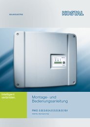
4.9 Navigation auf dem Display<br />
14<br />
Taste (A) Escape:<br />
Mit dieser Taste können Sie von den einzelnen Menü-Positionen zum<br />
Hauptmenü zurückkehren und das Setup-Menü verlassen.<br />
Taste (B) und (C) Pfeiltasten Aufwärts und Abwärts:<br />
Mit diesen Tasten können Sie die einzelnen Menü-Positionen durchlaufen<br />
oder Einstellungen im Setup-Menü vornehmen.<br />
Taste (D) Enter:<br />
Mit dieser Taste begeben Sie sich auf eine andere Menü-Ebene oder<br />
bestätigen Sie eine Wahlmöglichkeit im Setup-Menü.<br />
Sobald zum ersten Mal eine Spannung an der AC-Seite des Wechselrichters<br />
ansteht, müssen Sie die gewünschte Sprache auswählen. Es sind die folgenden<br />
Sprachen auswählbar: Deutsch, Englisch, Französisch, Spanisch und Niederländisch.<br />
Danach erscheint die folgende Anzeige in der gewählten Sprache:<br />
‘Warnung: Länderauswahl: nur einmal erlaubt, siehe Anleitung’<br />
1<br />
2<br />
3<br />
4<br />
5<br />
6<br />
�<br />
�<br />
�<br />
�<br />
�<br />
�<br />
�<br />
�<br />
�<br />
�<br />
�<br />
�<br />
Drücken Sie die Enter-Taste um fortzufahren.<br />
Auf dieser Anzeige kann die Länderauswahl vorgenommen werden.<br />
Wählen Sie mit Hilfe der Pfeiltasten das gewünschte Land aus. Drücken Sie<br />
anschließend die Enter-Taste, um Ihre Auswahl zu bestätigen.<br />
Nach der Auswahl des Landes wird die Einstellung angezeigt und Sie werden<br />
gebeten, die Einstellung zu bestätigen. Wurde das falsche Land ausgewählt,<br />
können Sie jetzt durch Drücken der Escape-Taste zur Auswahlliste<br />
zurückkehren. Sind Sie mit dem gewählten Land einverstanden, bestätigen<br />
Sie die Auswahl mit der Enter-Taste. Jetzt erscheint die normale Anzeige.<br />
�<br />
Es besteht die Möglichkeit, den Wechselrichter von Hand ein- und<br />
auszuschalten. Bei Lieferung ist der Wechselrichter standardmäßig<br />
ausgeschaltet. Diese Einstellung kann in Menü 2-1 des Wechselrichters<br />
geändert werden.<br />
Drücken Sie die Enter-Taste um fortzufahren.<br />
Gehen Sie mit den Pfeiltasten zu Menü und drücken Sie erneut die Enter-<br />
Taste.<br />
Dies ist die Anzeige, mit der der Wechselrichter ein- und ausgeschaltet<br />
werden kann. Drücken Sie die Enter-Taste.<br />
�<br />
Unter dem Text ist der aktuelle Status angegeben. Der Wechselrichter<br />
kann jetzt ein- und ausgeschaltet werden, indem erneut die Enter-Taste<br />
gedrückt wird. Wird der Wechselrichter manuell eingeschaltet, kann es<br />
einige Zeit dauern, bis er aktiv wird. Anschließend ist der Wechselrichter<br />
vollständig installiert.<br />
DE<br />
7 6.439 | 10.04<br />
B<br />
A D<br />
C
B<br />
A D<br />
C<br />
DE<br />
5 Betrieb des <strong>StecaGrid</strong><br />
5.1 Betriebs- und Störungsanzeige mittels einer LED<br />
Auf der Vorderseite der Steuereinheit ist eine LED angebracht, die den Betriebszustand<br />
des/der Wechselrichter(s) angibt. Beim Starten leuchtet die LED gedimmt<br />
grün. Das Starten beginnt mit einer Reihe von Überprüfungsschritten (die einige<br />
Sekunden in Anspruch nehmen). Wenn die Leistung der Solarmodule hoch genug<br />
ist, wird der Wechselrichter auf den ‚aktiven Modus’ schalten. Bei geringer<br />
Einstrahlung kann es vorkommen, dass die Solarmodule nicht genügend Leistung<br />
erzeugen, um sie in das Stromnetz einzuspeisen.<br />
Auf dem Display erscheint dann die Meldung: ‘Stand By’ – Ruhezustand.<br />
Eine Übersicht über die anderen Meldungen und den entsprechenden LED-Status<br />
finden Sie in Tabelle 1.<br />
LED-Status System Status Erklärung, Verweise<br />
Grün – gedimmt Sleep Mode – Schlafbetrieb Das System ist auf Energiesparbetrieb<br />
geschaltet (Nachtausschaltung).<br />
Grün Active Mode – Normalbetrieb Das System läuft (normaler Betriebszustand)<br />
Grün – blinkend Standby Mode – Ruhebetrieb Das System kann Energie liefern.<br />
Rot – blinkend Partial active – Teilstörung Es liegt ein Fehler an einem der Wechselrichter<br />
vor (die anderen liefern noch<br />
Energie). Die Fehlermeldung kann über<br />
das Display aufgerufen werden.<br />
Rot Error – Fehler Der Wechselrichter hat einen Fehler<br />
(es wird keine Energie geliefert). Die<br />
Fehlermeldung kann über das Display<br />
aufgerufen werden.<br />
Off Aus Es ist keine Netzspannung anwesend.<br />
Tabelle 1: Eine Übersicht über die Meldungen der LEDs<br />
Das Hauptmenü<br />
Das Display dient sowohl für die Vorgabe von (neuen) Einstellungen als auch für<br />
die Anzeige von Systemdaten.<br />
Navigation auf dem Display<br />
7 6.439 | 10.04<br />
Taste (A) Escape:<br />
Mit dieser Taste können Sie von den einzelnen Menü-Positionen zum<br />
Hauptmenü zurückkehren und das Setup-Menü verlassen.<br />
Taste (B) und (C) Pfeiltasten Aufwärts und Abwärts:<br />
Mit diesen Tasten können Sie die einzelnen Menü-Positionen durchlaufen<br />
oder Einstellungen im Setup-Menü vornehmen.<br />
Taste (D) Enter:<br />
Mit dieser Taste begeben Sie sich auf eine andere Menü-Ebene oder<br />
bestätigen Sie eine Wahlmöglichkeit im Setup-Menü.<br />
Je nach eingestelltem Benutzer-Profil können durch Betätigen der Aufwärts- bzw.<br />
Abwärts-Taste 9 Menüs angewählt werden.<br />
Dabei können Benutzer-Profile auf 3 Niveaus eingestellt werden.<br />
•<br />
•<br />
•<br />
�<br />
�<br />
�<br />
�<br />
�<br />
�<br />
Basis [Untermenü: 1- -5]<br />
Fortgeschritten [Untermenü: 1- -3-5]<br />
Service [Untermenü: 1- -3-4-5]<br />
Je nach implementierten Optionen können noch die Untermenüs 7 und 8 hinzukommen.<br />
Mit Hilfe dieser Menüstruktur kann ein Benutzer alle erforderlichen<br />
Daten aufrufen.<br />
Eine Übersicht über alle Funktionen mit einer kurzen Beschreibung finden Sie in<br />
der Anlage. Dort ist in der linken Spalte eine Zahl angegeben. Diese Zahl steht<br />
auch rechts oben in der Anzeige auf dem Display und gibt den Ort und die<br />
Auswahl eines Menüs oder einer Funktion an. Wenn zum Beispiel der Ort einer<br />
15
Menü-Position mit 5-3-3 bezeichnet wird, bedeutet dies, dass in dem Hauptmenü<br />
zuerst Menü 5 (Einstellungen) gewählt werden muss. Anschließend wird das<br />
Untermenü 3 (Sprache) gewählt. Die dritte Position ist dann 5-3-3 (Deutsch). In<br />
diesem Beispiel kann die auf dem Display angezeigte Sprache in Deutsch geändert<br />
werden, indem man hier die Enter-Taste betätigt.<br />
Positionsnummer<br />
16<br />
Enter<br />
� Aufwärts<br />
� Abwärts<br />
� Aufwärts<br />
� Abwärts<br />
� Aufwärts<br />
� Abwärts<br />
� Aufwärts<br />
� Abwärts<br />
Menü-Position Bedeutung<br />
1-1-1-1 Aktuelle Leistung Zeigt die aktuelle Gesamtleistung von <strong>Master</strong><br />
und <strong>Slave</strong>-Einheiten an.<br />
1-1-1- Max. Leistung überhaupt Die höchste Gesamtleistung, die <strong>Master</strong> und<br />
<strong>Slave</strong>-Einheiten erreicht haben.<br />
1-1-1-3 Reset Leistung überhaupt Drücken Sie die Enter-Taste, um Max. Leistung<br />
überhaupt (1-1-1- ) zu resetten.<br />
1-1- -1<br />
bis<br />
1-1- -8<br />
1-1-3-1<br />
bis<br />
1-1-3-13<br />
1-1-4-1<br />
bis<br />
1-1-4-x<br />
<strong>StecaGrid</strong><br />
System<br />
Leistung<br />
Menü<br />
Nach Leistung<br />
> Ertrag<br />
Status<br />
Messwerte<br />
Ertrag<br />
> Status<br />
Messwerte<br />
Ertrag<br />
Status<br />
> Messwerte<br />
Status<br />
Messwerte<br />
> Systemdaten<br />
Messwerte<br />
Systemdaten<br />
> Einstellungen<br />
Datum von heute<br />
bis<br />
Datum vor 7 Tagen<br />
Aktueller Monat<br />
bis<br />
1 Monate zurück<br />
Aktuelles Jahr<br />
bis<br />
Jahr der Anschaffung<br />
Die gesamte Energiemenge, die an diesem<br />
Tag durch <strong>Master</strong> und <strong>Slave</strong>-Einheiten erzeugt<br />
wurde.<br />
Die gesamte Energiemenge, die in dem betreffenden<br />
Monat durch <strong>Master</strong> und <strong>Slave</strong>- Einheiten<br />
erzeugt wurde.<br />
Die gesamte Energiemenge, die in dem betreffenden<br />
Jahr durch <strong>Master</strong> und <strong>Slave</strong>-Einheiten<br />
erzeugt wurde.<br />
1-1-5-1 Gesamtenergie Die Gesamtenergie, die durch <strong>Master</strong> und <strong>Slave</strong>-<br />
Einheiten seit dem Zeitpunkt der Installation<br />
erzeugt wurde.<br />
1- -1-1 Aktuelle Leistung Gibt die Leistung an, wie sie in diesem Moment<br />
vorliegt (<strong>Master</strong> und <strong>Slave</strong>s einzeln).<br />
1- -1- Max. Leistung überhaupt Die höchste Leistung, die seit der letzten System-Rückstellung<br />
erreicht wurde (<strong>Master</strong> und<br />
<strong>Slave</strong>s einzeln).<br />
1- -1-3 Rückstellung der max. Leistung<br />
überhaupt<br />
1<br />
2<br />
3<br />
4<br />
5<br />
� Aufwärts<br />
� Abwärts<br />
Enter<br />
Enter<br />
Enter<br />
Enter<br />
Enter<br />
Schirm auffrischen<br />
Die höchste Leistung von 1- -1- wird rückgestellt.<br />
Nach Drücken der Enter-Taste bei dieser<br />
Menü-Position ist die Leistung von 1- -1- die<br />
höchste Leistung seit dem Betätigen der Enter-<br />
Taste bei dieser Menü-Position.<br />
DE<br />
7 6.439 | 10.04
DE<br />
1- - -1<br />
bis<br />
1- - -8<br />
1- -3-1<br />
bis<br />
1- -3-13<br />
1- -4-1<br />
bis<br />
1- -4-x<br />
7 6.439 | 10.04<br />
Datum von heute<br />
bis<br />
Datum vor 7 Tagen<br />
Aktueller Monat<br />
bis<br />
1 Monate zurück<br />
Aktuelles Jahr bis Jahr der Anschaffung<br />
(max. 5 Jahre)<br />
Die Energiemenge, die an diesem Tag erzeugt<br />
wurde (<strong>Master</strong> und <strong>Slave</strong>s einzeln).<br />
Die Energiemenge, die in dem betreffenden Monat<br />
erzeugt wurde (<strong>Master</strong> und <strong>Slave</strong>s einzeln).<br />
Die Energiemenge, die in dem betreffenden Jahr<br />
erzeugt wurde (<strong>Master</strong> und <strong>Slave</strong>s einzeln).<br />
1- -5-1 Gesamtenergie Die Gesamtenergie, die seit dem Zeitpunkt der<br />
Installation erzeugt wurde (<strong>Master</strong> und <strong>Slave</strong>s<br />
einzeln).<br />
-1-1 Manuell ein/aus Durch Drücken der Enter-Taste können bei dieser<br />
Menü-Position <strong>Master</strong> + <strong>Slave</strong>s ein- und ausgeschaltet<br />
werden.<br />
- -1 Wechselrichter a Gibt den Status des <strong>Master</strong>s an. Möglichkeiten:<br />
aktiv, Standby, Sleep, aus<br />
- - Wechselrichter b Gibt den Status des 1. <strong>Slave</strong> an. Möglichkeiten:<br />
aktiv, Standby, Sleep, aus<br />
- -3 Wechselrichter c Gibt den Status des . <strong>Slave</strong> an. Möglichkeiten:<br />
aktiv, Standby, Sleep, aus<br />
-3-1<br />
bis<br />
-3-n<br />
Nachricht 1<br />
bis<br />
Nachricht n<br />
3-1-1 Hauptspannung, Frequenz,<br />
Strom<br />
Nur zutreffend, wenn eine Fehlermeldung vorliegt.<br />
Hier wird die Fehlermeldung angezeigt.<br />
Gibt die aktuellen Messwerte für die Netzspannung,<br />
den in das Netz eingespeisten Strom und<br />
die Netzfrequenz an.<br />
3- -1 PV-Spannung Gibt die DC-Spannung beider Eingänge für<br />
sowohl den <strong>Master</strong> als auch die <strong>Slave</strong>s an.<br />
3- - PV-Strom Gibt die DC-Strom beider Eingänge für sowohl<br />
den <strong>Master</strong> als auch die <strong>Slave</strong>s an.<br />
3- -3 PV-Leistung Gibt die DC-Leistung an beiden Eingängen sowohl<br />
für den <strong>Master</strong> als auch für die <strong>Slave</strong>s an.<br />
3- -4 Netzstrom Gibt den in das Netz eingespeisten Strom für<br />
sowohl den <strong>Master</strong> als auch die <strong>Slave</strong>s an.<br />
3- -5 Primäre Busspannung Eine interne Spannung im Wechselrichter. Der<br />
Wert dieser Spannung gibt dem Fachmann Aufschluss<br />
über den Zustand des Wechselrichters,<br />
wenn eine Störung vorliegt.<br />
3- -6 Sekundäre Busspannung Eine interne Spannung im Wechselrichter. Der<br />
Wert dieser Spannung gibt dem Fachmann Aufschluss<br />
über den Zustand des Wechselrichters,<br />
wenn eine Störung vorliegt.<br />
3- -7 Interne Temperatur Gibt die aktuelle Innentemperatur des Wechselrichters<br />
für sowohl den <strong>Master</strong> als auch die<br />
<strong>Slave</strong>s an.<br />
4-1 System Gibt den Typ, die Seriennummer und die Versionsnummer<br />
der betreffenden Komponente an.<br />
4- Wechselrichter a Gibt den Typ, die Seriennummer und die Versionsnummer<br />
der betreffenden Komponente an.<br />
4-3 Wechselrichter b Gibt den Typ, die Seriennummer und die Versionsnummer<br />
der betreffenden Komponente an.<br />
4-4 Wechselrichter c Gibt den Typ, die Seriennummer und die Versionsnummer<br />
der betreffenden Komponente an.<br />
4-5 Display Gibt den Typ, die Seriennummer und die Versionsnummer<br />
der betreffenden Komponente an.<br />
4-6 RFM Gibt den Typ, die Seriennummer und die Versionsnummer<br />
der betreffenden Komponente an.<br />
5-1-1 Zeit Wenn hier die Taste Enter gedrückt wird,<br />
beginnt die Uhrzeit zu blinken. Sie kann durch<br />
Drücken der Pfeiltasten eingestellt werden.<br />
Die Bestätigung der Einstellung erfolgt durch<br />
Drücken der Enter-Taste.<br />
5-1- -1 1 Wenn hier die Taste Enter gedrückt wird, wird<br />
die Uhrzeit im 1 -Stunden-Format angezeigt,<br />
also mit der Angabe AM/PM für den Vormittag<br />
bzw. den Nachmittag.<br />
5-1- - 4 Wenn hier die Taste Enter gedrückt wird, wird<br />
die Uhrzeit im 4-Stunden-Format angezeigt.<br />
5-1-3 Datum Wenn hier die Taste Enter gedrückt wird,<br />
beginnt das Datum zu blinken. Es kann durch<br />
Drücken der Pfeiltasten eingestellt werden.<br />
Die Bestätigung der Einstellung erfolgt durch<br />
Drücken der Enter-Taste.<br />
17
5-1-4-1<br />
bis<br />
5-1-4-3<br />
18<br />
Jjjj-mm-tt<br />
tt-mm-jjjj<br />
mm-tt-jjjj<br />
Durch Auswählen des betreffenden Eintrags<br />
wird das entsprechende Format für die Anzeige<br />
des Datums vorgegeben.<br />
5- -1-1 Immer eingeschaltet Durch Auswählen dieses Eintrags ist die Display-<br />
Beleuchtung immer eingeschaltet.<br />
5- -1- Immer ausgeschaltet Durch Auswählen dieses Eintrags ist die Display-<br />
Beleuchtung immer ausgeschaltet.<br />
5- -1-3 Energiesparbetrieb Durch Auswählen dieses Eintrags wird die<br />
Display-Beleuchtung automatisch eingeschaltet,<br />
sobald die Navigationstasten betätigt werden.<br />
Nach Betätigung der Tasten bleibt das Display<br />
eine gewisse Zeit lang eingeschaltet, bevor sich<br />
die Beleuchtung automatisch ausschaltet.<br />
5-3-1 English Durch Auswählen dieses Eintrags wird Englisch<br />
als Sprache für die Anzeige gewählt.<br />
5-3- Nederlands Durch Auswählen dieses Eintrags wird Niederländisch<br />
als Sprache für die Anzeige gewählt.<br />
5-3-3 Français Durch Auswählen dieses Eintrags wird Französisch<br />
als Sprache für die Anzeige gewählt.<br />
5-3-4 Deutsch Durch Auswählen dieses Eintrags wird Deutsch<br />
als Sprache für die Anzeige gewählt.<br />
5-3-5 Español Durch Auswählen dieses Eintrags wird Spanisch<br />
als Sprache für die Anzeige gewählt.<br />
5-4-1 Basis Bei diesem Profil werden nur die Basisfunktionen<br />
angezeigt (Menü 1, , 5, wenn vorhanden<br />
8).<br />
5-4- Fortgeschritten Bei diesem Profil erhält der Benutzer maximalen<br />
Einblick in sein System (Menü 1, , 3, 5, wenn<br />
vorhanden 8).<br />
5-4-3 Service Dieses Profil entspricht dem Profil für Fortgeschrittene<br />
und enthält zusätzlich Menü 4. Der<br />
Installateur erhält auch Zugang zu der Länderauswahl.<br />
Nachfolgende Menüpunkte stehen nur bei Erstinbetriebnahme zur Verfügung:<br />
5-5-1 Default Die standardmäßigen Ländereinstellungen,<br />
mit denen der Wechselrichter ausgeliefert<br />
wird. Sie stehen immer zur Verfügung.<br />
5-5- Niederlande Die Einstellungen für die Niederlande.<br />
5-5-3 Belgien Die Einstellungen für Belgien.<br />
5-5-4 Frankreich Die Einstellungen für Frankreich.<br />
5-5-5 Spanien Die Einstellungen für Spanien.<br />
5-5-6 Großbritannien Die Einstellungen für Großbritannien.<br />
5-5-7 Deutschland Die Einstellungen für Deutschland.<br />
DE<br />
7 6.439 | 10.04
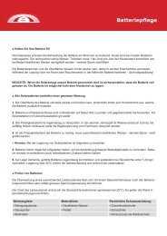
X A B C<br />
X) Steuereinheit<br />
A) Wechselrichter A<br />
B) Wechselrichter B<br />
C) Wechselrichter C<br />
Sicherungen im Wechselrichter<br />
• Null- und Netzanschluss: 1 A<br />
(träge, hohe Schaltleistung, 6,3 x 30 mm)<br />
Steca-Sachnummer: 719.498<br />
• Netzteil Steuereinheit: A<br />
(träge, 5 x 0 mm)<br />
DE<br />
6 Störungsbeseitigung<br />
6.1 Fehlermeldungen<br />
Falls der <strong>StecaGrid</strong> eine Störung erkennt, erscheint augenblicklich ein Werkzeugsymbol<br />
auf dem Display. Dieses Zeichen steht in der Startanzeige rechts<br />
unten oder in den Menüanzeigen rechts oben hinter der „Positionsnummer“. Der<br />
<strong>StecaGrid</strong> kann verschiedene Fehlermeldungen anzeigen:<br />
•<br />
•<br />
•<br />
•<br />
Verständige Service (Relais)<br />
Verständige Service (DC-ABC)<br />
Verständige Service (NTC-ABC)<br />
Verständige Service (SDL ABC)<br />
Sollte eine dieser Störungen erscheinen, setzen Sie sich bitte umgehend mit<br />
Ihrem Installateur in Verbindung.<br />
Außerdem gibt es Meldungen, die keinen Einfluss auf die primäre Funktion des<br />
Geräts haben. Diese Meldungen werden auf dem Display mit einem blinkenden<br />
Ausrufezeichen angezeigt. Den genauen Meldetext finden Sie auf dem Display<br />
unter „Status - Nachrichten“. Folgende Meldungen können erscheinen:<br />
• Wechselrichter ABC Netzfrequenz hoch<br />
• Wechselrichter ABC Netzfrequenz niedrig<br />
• Wechselrichter ABC Netzspannung hoch<br />
• Wechselrichter ABC Netzspannung zu hoch<br />
• Wechselrichter ABC Netzspannung niedrig<br />
• Wechselrichter ABC Netzspannung zu niedrig<br />
• Wechselrichter ABC PV-Spannung zu hoch<br />
• Wechselrichter ABC DC-AC Schutz aktiv<br />
• Wechselrichter ABC Temperatur zu hoch<br />
• Wechselrichter ABC nicht synchronisiert<br />
• Überprüfe Wechselrichter ABC (COMM)<br />
Dies sind zeitbegrenzte Warnungen. Sie brauchen keine Maßnahmen zu ergreifen.<br />
6.2 Störungsbeseitigung<br />
Die Beseitigung von Störungen am Wechselrichter/an den Wechselrichtern beschränkt<br />
sich auf den Ersatz von Sicherungen in der Steuereinheit, wobei diese<br />
Arbeiten nur durch einen Installateur durchgeführt werden dürfen. Sowohl im<br />
Null- als auch im Netzanschluss jedes Wechselrichters ist eine Sicherung von 1<br />
A (träge, hohe Schaltleistung, 6,3 x 30 mm) vorgesehen. Eine Sicherung von A<br />
(träge, 5 x 0 mm) schützt das Elektronik-Netzteil der Steuereinheit. Ersatzsicherungen<br />
müssen immer vom gleichen Typ wie die ursprüngliche Sicherung sein<br />
und die gleichen Werte aufweisen. Sorgen Sie immer dafür, dass beim Ersetzen<br />
einer Sicherung die AC-Seite des Wechselrichters spannungsfrei gemacht ist. Falls<br />
eine der Sicherungen des Wechselrichters defekt ist, empfiehlt es sich, die zugehörige<br />
Sicherung derselben Gruppe ebenfalls zu ersetzen. Kontrollieren Sie anschließend,<br />
ob ein Defekt am Wechselrichter die Ursache für das Durchbrennen<br />
der Sicherung ist und tauschen Sie erforderlichenfalls den Wechselrichter aus.<br />
6.3 Wartung<br />
Dank seiner Ausführung ist der <strong>StecaGrid</strong> praktisch wartungsfrei, zumal er keine<br />
Bauteile enthält, die sich abnutzen können (Ventilator u.ä.).<br />
Dennoch empfiehlt es sich, regelmäßige Kontrollen durchzuführen.<br />
Dabei ist besonders darauf zu achten, dass die Kühlplatten an der Rückseite des<br />
<strong>StecaGrid</strong> staubfrei gehalten werden.<br />
Bei Installation des Wechselrichters bzw. der Wechselrichter in einer mehr oder<br />
weniger staubigen Umgebung kommt es infolge des natürlichen stärkeren Luftstroms<br />
durch die Kühlrippen schneller zu einer Verschmutzung.<br />
Bei einer Verschmutzung dieser Kühlplatte wird die Wärmeabfuhr beeinträchtigt,<br />
was ein schnelleres Erreichen der Leistungsbegrenzung bei niedrigeren Umgebungstemperaturen<br />
als den genannten 40 °C und somit eine unnötig herabgesetzte<br />
Stromerzeugung zur Folge haben kann.<br />
Das Wechselrichtergehäuse kann mit einem feuchten Tuch gereinigt werden.<br />
Benutzen Sie keine Reinigungsmittel, die das Kunststoff-/Aluminium-Verbundgehäuse<br />
angreifen können.<br />
7 6.439 | 10.04<br />
19
7 Technische Daten<br />
Eingangsdaten (PV-seitig)<br />
0<br />
<strong>StecaGrid</strong> 2<strong>000+</strong> D<br />
<strong>Master</strong><br />
7 6.439 | 10.04<br />
<strong>StecaGrid</strong> 2<strong>000+</strong><br />
<strong>Master</strong><br />
Eingangsspannung, Arbeitsbereich 80 V … 400 V DC<br />
Nennspannung DC 300 V DC<br />
Maximale Startspannung 410 V DC<br />
<strong>StecaGrid</strong> 2<strong>000+</strong><br />
<strong>Slave</strong><br />
Maximale Eingangsspannung für Stromeinspeisung Upv 450 V DC (höhere Spannungen können das Gerät beschädigen)<br />
Minimale Eingangsspannung für Netzeinspeisung > 80 V<br />
Abschaltspannung 50 V<br />
Nennstrom DC 7 A DC<br />
Maximaler Eingangsstrom Ipv x 8 A DC [Strom begrenzt durch Wechselrichter]<br />
oder<br />
1 x 16 A DC [Eingänge parallel]<br />
Trennungsprinzip HF-Trafo mit galvanischer Trennung und verstärkter Isolierung<br />
Thermische Überwachung Ja<br />
Verpolungsschutz Ja<br />
Maximale DC-Eingangsleistung 1075 W [pro Eingang]<br />
oder<br />
150 W [ Eingänge parallel]<br />
Maximal empfohlene PV-Leistung 400 Wp<br />
Leistungsabsenkung / Begrenzung Automatisch bei<br />
- Höherer bereitgestellter Eingangsleistung (> 1,075 kW/Eingang)<br />
- Unzureichender Kühlung des Geräts<br />
- Eingangsströme > x 8 A DC oder 1x16 A (Eingänge parallel).<br />
(Höhere Ströme werden durch das Gerät begrenzt und beschädigen daher den Wechselrichter<br />
nicht)<br />
DC-Anschlüsse MultiContact MC 4 (Solarline )<br />
Ausgangsdaten (Netzseite)<br />
Ausgangsnennleistung 000 W AC<br />
Maximale Ausgangsleistung 000 W AC<br />
Netzspannung 190 ... 65 V AC [abhängig von den Ländereinstellungen]<br />
Netztyp L/N + PE<br />
Netzfrequenz 47,5 ... 5 Hz [abhängig von den Ländereinstellungen]<br />
Ausgangsstrom nominal 8,7 A AC bei 30 V AC<br />
Ausgangsstrom max. 10 A AC<br />
Leistungsfaktor > 0,95<br />
Klirrfaktor < 5 % (bei maximaler Leistung)<br />
Abschaltwert im Inselbetrieb [Siehe Ländertabelle (Anlage)]<br />
Maximaler Wirkungsgrad 95 %<br />
Europäischer Wirkungsgrad 93,3 % 93,3 % 93,5 %<br />
MPP Wirkungsgrad > 99%<br />
Teilwirkungsgrade (bei 5, 10, 0, 30, 50, 100 % der Nennleistung) 78, 8 %, 86,8 %, 91,7 %,<br />
93,3 %, 94,4 %, 95,0 %<br />
Wirkungsgradminderung bei Erhöhung der Umgebungstemperatur<br />
(bei Temperaturen > 40 °C)<br />
78,8 %, 86,8 %, 91,7 %,<br />
93,3 %, 94,4 %, 95,0 %<br />
Wirkungsgradminderung bei Abweichung von der DC Nennspannung 0,006 % / V<br />
Umgebungstemperaturbereich (Tumg.) - 5 ... +60 °C<br />
Leistungs-Derating bei Voll-Leistung Ab 40 ° (Tumg.)<br />
Einschaltleistung 0 W<br />
Ausschaltleistung 18 W<br />
Standby-Leistung 3 W<br />
% / °C<br />
80, %, 87,5 %, 9 ,0 %, 93,5 %,<br />
94,6 %, 95,1 %<br />
Eigenverbrauch des Wechselrichters (Nachtbetrieb) 1,3 W 1,0 W 0 W<br />
AC-Anschluss WAGO ,5 - 6 mm² über <strong>Master</strong><br />
Normen und Prüfzeichen<br />
EMV EN 61000-6-3 (EN 55014 und EN 550 Klasse B)<br />
EN 61000-6-<br />
Sicherheitsrichtlinie EN 6 103 (EN 50178) und IEC 60950*<br />
Servicekategorie Außenbereich<br />
Verschmutzungsgrad II<br />
Schutzart IP65 IP65 IP65<br />
Luftfeuchtigkeit 0 ... 95 %<br />
Prüfbescheinigung Unbedenklichkeitsbescheinigung, CE<br />
Abmessungen und Gewicht<br />
Abmessungen (B x H x T): 351 x 54 x 140 mm 351 x 54 x 140 mm 6 x 535 x 140 mm<br />
Masse: ca. 11 kg ca. 11 kg ca. 9 kg<br />
DE
Sonstiges<br />
Netzüberwachung konform zu<br />
DIN VDE 01 6-1-1<br />
7 6.439 | 10.04<br />
siehe Ländertabelle -<br />
Isolationsüberwachung keine, da galvanische Trennung durch HF-Trafo im Gerät<br />
Anzeige Display, LED -<br />
Geräuschpegel < 3 dBA<br />
* erweitert um die Anforderungen des Entwurfes IEC 6 109-1/- .<br />
DE<br />
8 Gewährleistungs- und Garantiebestimmungen<br />
Garantiebedingungen für Produkte der Steca Elektronik GmbH<br />
1. Material- oder Verarbeitungsfehler<br />
Die Garantie gilt nur für Material- und Verarbeitungsfehler, soweit diese auf<br />
mangelhaftes fachmännisches Können seitens Steca zurückzuführen sind.<br />
Steca behält sich das Recht vor, nach eigenem Ermessen die defekten Produkte<br />
zu reparieren, anzupassen oder zu ersetzen.<br />
2. Allgemeine Informationen<br />
Auf alle Produkte hat der Kunde entsprechend den gesetzlichen Regelungen<br />
Jahre Gewährleistung.<br />
Für dieses Produkt von Steca übernehmen wir gegenüber dem Fachhandel eine<br />
freiwillige Garantie von 5 Jahren ab Rechnungs- bzw. Belegdatum. Diese freiwillige<br />
Garantie gilt für Produkte, die innerhalb eines EU-Landes verkauft wurden.<br />
Die gesetzlichen Gewährleistungsrechte werden durch die Garantie nicht eingeschränkt.<br />
Um die Garantie in Anspruch nehmen zu können, muss der Kunde den Zahlungsnachweis<br />
(Kaufbeleg) vorlegen.<br />
Sollte der Kunde ein Problem feststellen, hat er sich mit seinem Installateur oder<br />
der Steca Elektronik GmbH in Verbindung zu setzen.<br />
3. Garantieausschluss<br />
Die oben unter Punkt 1 beschriebenen Garantien auf Produkte von der Steca<br />
Elektronik GmbH gelten nicht für den Fall, dass der Fehler zurückzuführen ist auf:<br />
(1) Spezifikationen, Entwurf, Zubehör oder Komponenten, die durch den Kunden<br />
oder auf Wunsch des Kunden zu dem Produkt hinzugefügt wurden, oder spezielle<br />
Anweisungen des Kunden in Bezug auf die Produktion des Produkts, die Kopplung<br />
(von Steca Produkten) mit irgendwelchen Produkten, die nicht ausdrücklich von der<br />
Steca Elektronik GmbH genehmigt sind; ( ) Modifikationen oder Anpassungen am<br />
Produkt durch den Kunden, oder andere dem Kunden zuzurechnende Ursachen; (3)<br />
die nicht vorschriftsmäßige Anordnung oder Montage, auf falsche oder fahrlässige<br />
Behandlung, Unfall, Transport, Überspannung, Lagerung oder Beschädigung durch<br />
den Kunden oder Dritte; (4) ein unvermeidbares Unglück, Brand, Explosion, Bau oder<br />
Neubau irgendeiner Art in der Umgebung, in der das Produkt angeordnet ist, auf<br />
Naturphänomene wie Erdbeben, Flut oder Sturm, oder auf irgendeine Ursache außerhalb<br />
des Einflussbereichs von der Steca Elektronik GmbH; (5) irgendeine Ursache,<br />
die nicht vorherzusehen oder zu vermeiden ist mit den angewendeten Technologien,<br />
die bei der Zusammenstellung des Produkts eingesetzt wurden; (6) wenn die<br />
Serienummer und/oder die Typnummer manipuliert oder unlesbar gemacht wurde;<br />
(7) den Einsatz der Solarprodukte in einem beweglichen Objekt, zum Beispiel bei<br />
Schiffen, Wohnwagen o. ä.<br />
Die in dieser Bedienungsanleitung genannte Garantie gilt nur für Konsumenten, die<br />
Kunde von der Steca Elektronik GmbH sind oder durch die Steca Elektronik GmbH<br />
autorisierte Wiederverkäufern sind. Die hier genannte Garantie ist nicht auf Dritte<br />
übertragbar. Der Kunde wird seine sich hieraus ergebenden Rechte oder Pflichten<br />
nicht auf irgendeine Weise übertragen, ohne hierfür zuvor eine schriftliche Genehmigung<br />
von der Steca Elektronik GmbH eingeholt zu haben. Außerdem wird die Steca<br />
Elektronik GmbH in keinem Fall haftbar sein für indirekte Schäden oder entgangenen<br />
Ertrag. Vorbehaltlich eventuell geltender zwingender Rechtsvorschriften ist<br />
die Steca Elektronik GmbH auch nicht für andere Schäden haftbar als für diejenigen,<br />
für welche die Steca Elektronik GmbH hiermit ausdrücklich ihre Haftung anerkannt<br />
hat.<br />
1
9 Kontakt<br />
Bei Reklamationen und Störungen bitten wir Sie, sich mit Ihrem lokalen Händler<br />
in Verbindung zu setzen, bei dem Sie das Produkt gekauft haben. Dieser wird<br />
Ihnen in allen Belangen weiterhelfen.<br />
Europa<br />
Steca Elektronik GmbH<br />
Mammostrasse 1<br />
87700 Memmingen<br />
Germany<br />
Fon +49 700 STECAGRID<br />
+49 (0) 700 783 4743<br />
Fax +49 8331 8558 13<br />
E-Mail service@stecasolar.com<br />
Internet www.stecasolar.com<br />
Anhang<br />
Glossar<br />
In diesem Handbuch werden einige Fachausdrücke verwendet, die im Folgenden<br />
kurz erläutert werden:<br />
AC Alternating Current, Wechselstrom<br />
Steuereinheit Teil des <strong>Master</strong>-Wechselrichters, der u.a. für<br />
den Anschluss der AC-Kabel und Datenkabel<br />
von sowohl dem <strong>Master</strong> als auch dem <strong>Slave</strong><br />
vorgesehen ist.<br />
Autonomes System Ein System, das nicht mit dem öffentlichen<br />
Stromnetz gekoppelt ist und Energie, die nicht<br />
sofort gebraucht wird, in Akkus speichert.<br />
CE Ein Prüfzeichen, das angibt, dass das Produkt<br />
der europäischen Anforderung entspricht.<br />
DC Direct Current, Gleichstrom<br />
Eingangsspannung Die Spannung der Solarmodule<br />
Eingangsstrom Der Strom, den die Solarmodule erzeugen<br />
EMV Elektromagnetische Verträglichkeit. Der<br />
Wechselrichter darf keine störenden elektromagnetischen<br />
Signale aussenden und auch<br />
nicht anfällig dafür sein.<br />
ENS ‘Einrichtung zur Netzüberwachung mit zwei<br />
selbständigen Schaltorganen in Reihe’. Ein<br />
Modul, das die Netzimpedanz misst. Bei einer<br />
zu großen Schwankung der Impedanz wird<br />
der Wechselrichter abgeschaltet. Der Einsatz<br />
dieses Moduls ist in Deutschland und Österreich<br />
obligatorisch.<br />
Europäischer Wirkungsgrad Ein Maß für den durchschnittlichen Wirkungsgrad<br />
eines Wechselrichters im Jahresverlauf<br />
IEC 60364-7-712 PV-Absatz der Installationsnorm für Gebäude<br />
Inselbetrieb Die Bezeichnung für den Betrieb eines Wechselrichters,<br />
ohne dass eine Netzspannung<br />
vorhanden ist.<br />
IP 65 Gibt an, wie gut ein Gerät gegen das Eindringen<br />
von Feuchtigkeit und Staub geschützt<br />
ist. Ein mit IP 65 spezifiziertes Gerät kann in<br />
Räumen und im Freien angeordnet werden.<br />
Isc Ishortcuit, siehe Kurzschlussstrom.<br />
Konnektor Stecker oder Buchse<br />
DE<br />
7 6.439 | 10.04
DE<br />
Kühlprofil Ein Profil auf der Rückseite, das für die Ableitung<br />
von Wärme vorgesehen ist und damit<br />
zur Kühlung des Wechselrichters dient.<br />
Kurzschlussstrom (STC) Der Strom, den die Solarmodule unter Standard-Testbedingungen<br />
erzeugen, wenn sie<br />
kurzgeschlossen sind.<br />
Ländertabelle Ein Wechselrichter schaltet sich automatisch<br />
ab, wenn das Stromnetz von bestimmten<br />
Werten abweicht. Diese Werte sind für jedes<br />
Land unterschiedlich und in der Ländertabelle<br />
aufgeführt.<br />
LED Light Emitting Diode, Leuchtdiode (Anzeigelampe)<br />
Leerlaufspannung Die Spannung, die ein Modul erzeugt, wenn<br />
kein Strom fließt.<br />
Leistungsabsenkung (Derating) Verminderung der vom Wechselrichter abgegebenen<br />
Leistung mit dem Ziel, die Temperatur<br />
im Inneren des Wechselrichters zu senken<br />
bzw. nicht weiter zu erhöhen.<br />
Lichtbogen Ein gefährlicher, durch die Luft fließender<br />
elektrischer Strom, der entsteht, wenn die<br />
Plus- und Minuspole einer hohen Spannung<br />
zu nahe zusammenkommen.<br />
<strong>Master</strong> Ein Wechselrichter, in dem mehrere zentrale<br />
Funktionen implementiert sind. Diese Funktionen<br />
sind auch für die sogenannten <strong>Slave</strong>-<br />
Wechselrichter vorgesehen, kommen aber nur<br />
im <strong>Master</strong> Gerät einmal vor.<br />
<strong>Master</strong><strong>Slave</strong>-Prinzip Ein <strong>Master</strong> steuert 1 oder <strong>Slave</strong>s<br />
Maximum Power Point Die Gleichspannung und der Gleichstrom<br />
eines Solarmoduls, bei dem das Modul die<br />
meiste Leistung erzeugt.<br />
MPPT Maximum Power Point Tracking: Eine Funktion<br />
des Wechselrichters, die dafür sorgt, dass<br />
die Solarmodule im Maximum-Power-Point<br />
arbeiten.<br />
Multi-Contact Hersteller einer bestimmten Steckerart<br />
NEN1010 Eine niederländische Norm für elektrische<br />
Installationen<br />
Netzgekoppeltes System Ein PV-System, das mit dem öffentlichen Netz<br />
verbunden ist<br />
Photovoltaischer Effekt Umwandlung von Licht in Elektrizität<br />
PV Photovoltaik, siehe ‘photovoltaischer Effekt’.<br />
PV-System Ein System, bei dem Solarmodule Elektrizität<br />
erzeugen.<br />
<strong>Slave</strong> Ein Wechselrichter, der durch den <strong>Master</strong><br />
gesteuert wird.<br />
Sleep-Modus Eine Betriebsart des Wechselrichters, um den<br />
Nachtverbrauch zu minimieren (Schlafbetrieb).<br />
Solarmodul Eine Einheit mit einer Anzahl in Reihe geschalteter<br />
Solarzellen. Die Solarzellen wandeln<br />
Licht in Spannung und Strom um.<br />
String Eine Anzahl von in Reihe geschalteten Solarmodulen<br />
Sub-D9 9-poliger Steckverbinder<br />
Systemkonfiguration Die Weise, in der mehrere Solarmodule untereinander<br />
geschaltet und gemeinsam mit dem<br />
Wechselrichter verbunden werden.<br />
Thermische Überwachung Eine Funktion des Wechselrichters, die si-<br />
7 6.439 | 10.04<br />
3
4<br />
cherstellt, dass die Temperatur innerhalb des<br />
Wechselrichters nicht zu stark ansteigt.<br />
Tumg Die Umgebungstemperatur (hier: beim Wechselrichter)<br />
Tyco Ein Steckersystem<br />
V(oc) Vopen circuit, siehe Leerlaufspannung<br />
Verpolungsschutz Eine Schutzvorrichtung, die verhindert, dass<br />
der positive Anschluss des Moduls mit dem<br />
negativen Anschluss des Wechselrichters verbunden<br />
wird.<br />
Wechselrichter Der Wechselrichter setzt den Gleichstrom<br />
der Solarmodule in einen für das öffentliche<br />
Stromnetz geeigneten Wechselstrom um.<br />
Auch als “Inverter” bezeichnet.<br />
Wirkungsgrad Hier: Prozentsatz der DC-Leistung, die in AC-<br />
Leistung umgesetzt wird.<br />
Notizen<br />
Wechselrichter<br />
Typ ...................................................................................................................<br />
Seriennummer .................................................................................................<br />
Installateur<br />
Betrieb .............................................................................................................<br />
Ansprechpartner ..............................................................................................<br />
Straße ..............................................................................................................<br />
PLZ ...................................................................................................................<br />
Stadt ................................................................................................................<br />
Telefonnummer ................................................................................................<br />
E-Mail ..............................................................................................................<br />
Anmerkungen<br />
........................................................................................................................<br />
........................................................................................................................<br />
........................................................................................................................<br />
........................................................................................................................<br />
........................................................................................................................<br />
........................................................................................................................<br />
........................................................................................................................<br />
........................................................................................................................<br />
........................................................................................................................<br />
........................................................................................................................<br />
........................................................................................................................<br />
........................................................................................................................<br />
........................................................................................................................<br />
DE<br />
7 6.439 | 10.04
�<br />
Installationsanleitung (Kurzversion)<br />
Montage<br />
1 2 3<br />
4 5 6<br />
7 8 9<br />
1. optional, nur bei Installation von <strong>Slave</strong>s<br />
. AC-Kabel muss spannungsfrei bleiben<br />
10<br />
- + - +<br />
2<br />
2 1 1<br />
Das AC-Kabel muss spannungsfrei bleiben<br />
DE<br />
(Optional)<br />
Das AC-Kabel muss spannungsfrei bleiben Das AC-Kabel muss spannungsfrei bleiben<br />
1. optional, nur bei Installation von <strong>Slave</strong>s<br />
. AC-Kabel muss spannungsfrei bleiben<br />
7 6.439 | 10.04<br />
1. optional, nur bei Installation von <strong>Slave</strong>s<br />
. AC-Kabel muss spannungsfrei bleiben<br />
ACHTUNG<br />
Die elektrischen Verbindungen müssen in der korrekten<br />
Reihenfolge vorgenommen werden!<br />
� Verbindung zum Netz herstellen<br />
� PV-Generator anschließen<br />
� Netzleitungs-Sicherheitsschalter schließen<br />
5
Installationsanleitung (Kurzversion)<br />
Inbetriebnahme<br />
6<br />
B<br />
A D<br />
C<br />
1 2<br />
3 4<br />
Navigation auf dem Display<br />
�<br />
�<br />
�<br />
Taste (A) Escape<br />
Taste (B) und (C) Pfeiltasten Aufwärts und Abwärts<br />
Taste (D) Enter<br />
Ländertabelle<br />
In der nachstehenden Tabelle sind die Vorgabewerte der Ländertabelle angegeben.<br />
Netzspannung<br />
(Abschaltwert)<br />
Default -10 % / + 6 %<br />
der Nennspannung (0,1 s)<br />
3100<br />
Niederlande<br />
3200<br />
Belgien<br />
3300<br />
Frankreich<br />
3400<br />
Spanien<br />
4400<br />
Großbritannien<br />
4900<br />
Deutschland<br />
4901<br />
Deutschland<br />
-10 % / +10 %<br />
der Nennspannung (0,1 s)<br />
- 0 % / +6 %<br />
der Nennspannung (0, s)<br />
- 0 % / +15 %<br />
der Nennspannung (0, s)<br />
-15 % / +10 %<br />
der Nennspannung (0, s)<br />
-10 % / +15 %<br />
der Nennspannung (1,5 s)<br />
- 0 % / +15 %<br />
der Nennspannung (0, s)<br />
- 0 % / +15 %<br />
der Nennspannung (0, s)<br />
*) Nur beim Typ <strong>StecaGrid</strong> <strong>000+</strong> D <strong>Master</strong>-M<br />
Netzfrequenz<br />
(Abschaltwert)<br />
+/- 0, Hz<br />
der Nennfequenz (0, s)<br />
+/- Hz der<br />
Nennfequenz ( s)<br />
+/- 0, Hz<br />
der Nennfequenz (0, s)<br />
- ,5 / + 0, Hz<br />
der Nennfequenz (0, s)<br />
+/- 1 Hz<br />
der Nennfequenz (0, s)<br />
+/- 1 Hz<br />
der Nennfequenz (0,5 s)<br />
- ,5 / + 0, Hz<br />
der Nennfequenz (0, s)<br />
- ,5 / + 0, Hz<br />
der Nennfequenz (0, s)<br />
Netzimpedanz-<br />
Überwachung<br />
ja, nach<br />
VDE 01 6-1-1*<br />
Wiederzuschaltzeit<br />
180 s<br />
Nicht zutreffend 0 s<br />
ja, nach<br />
VDE 01 6-1-1*<br />
30 s<br />
Nicht zutreffend 30 s<br />
Nicht zutreffend 180 s<br />
Nicht zutreffend 180 s<br />
ja, nach<br />
VDE 01 6-1-1*<br />
30 s<br />
Nicht zutreffend 30 s<br />
DE<br />
7 6.439 | 10.04<br />
�
DE<br />
7 6.439 | 10.04<br />
7
Content<br />
Safety ......................................................................................................... 9<br />
8<br />
Introduction ............................................................................................... 9<br />
1 About this manual ..................................................................................30<br />
1.1 Applicability ....................................................................................... 30<br />
1. Users .................................................................................................. 30<br />
1.3 Description of symbols ....................................................................... 30<br />
2 Safety ......................................................................................................31<br />
.1 Proper use .......................................................................................... 31<br />
. Improper use ..................................................................................... 31<br />
.3 Dangers during installation and commissioning ................................ 31<br />
.4 Dangers durring operation ................................................................ 31<br />
.5 Exclusion of liability ........................................................................... 31<br />
3 Technical structure of the <strong>StecaGrid</strong>.......................................................32<br />
3.1 General .............................................................................................. 3<br />
3. <strong>Master</strong>-slave principle ........................................................................ 3<br />
3.3 Cooling .............................................................................................. 3<br />
3.4 Safety aspects & applicable standards ............................................... 33<br />
3.5 Data communication ......................................................................... 33<br />
4 Installation ..............................................................................................34<br />
4.1 General requirements for installation................................................. 34<br />
4. Notes on installation .......................................................................... 34<br />
4.3 Installation ......................................................................................... 35<br />
4.4 Connecting (AC) the master inverter .................................................. 36<br />
4.5 Connecting (AC) the slave inverter(s) ................................................. 37<br />
4.6 Connecting (DC) master and slaves .................................................... 38<br />
4.7 Connecting the communications module (<strong>StecaGrid</strong> Connect) .......... 39<br />
4.8 Switching the grid voltage on for the first time ................................. 39<br />
4.9 Navigating the display ....................................................................... 40<br />
5 Operating the <strong>StecaGrid</strong>.........................................................................41<br />
5.1 Operation and fault display via an LED .............................................. 41<br />
6 Troubleshooting......................................................................................45<br />
6.1 Fault messages ................................................................................... 45<br />
6. Troubleshooting ................................................................................. 45<br />
6.3 Maintenance ...................................................................................... 45<br />
7 Technical data .........................................................................................46<br />
8 Guarantee and warranty conditions ............................................................ 47<br />
9 Contact ...................................................................................................48<br />
Appendix .......................................................................................................48<br />
Glossary ...................................................................................................... 48<br />
Notes .......................................................................................................... 50<br />
Installation instructions (Short version) .......................................................51<br />
Installation .................................................................................................. 51<br />
Commissioning ........................................................................................... 5<br />
Table of countries ....................................................................................... 5<br />
EN<br />
7 6.439 | 10.04
EN<br />
Safety<br />
WARNING<br />
Risk of death by electrocution!<br />
�<br />
The unit may only be connected to the grid by qualified personnel in accordance<br />
with the regulations of the local power supply company.<br />
Introduction<br />
A significant contribution to environmental protection can be made by using<br />
renewable energy sources as less CO is released into the Earth's atmosphere<br />
as well as other harmful gases following the burning of fossil fuels. One such<br />
renewable energy source is the sun.<br />
The sun's energy is converted using a so-called PV system (PV stands for photovoltaics;<br />
an explanation of this can be found in the glossary of specialist terms<br />
at the back of this manual). A PV system contains, amongst other things, an<br />
inverter. The inverter converts the direct current produced by the solar modules<br />
into alternating current which can be fed directly into the public power<br />
grid. The <strong>StecaGrid</strong> was designed for so-called "grid-connected systems". With<br />
these systems, the inverter is connected parallel to the public power grid.<br />
The solar power system feeds the grid-compliant alternating current via an additional<br />
feed-in meter (used for feed-in tariff) directly to the grid system of the<br />
grid system operator and is then available to all consumers connected to the<br />
grid. The energy used by the electricity consumer is then billed as normal using<br />
the existing consumption meter.<br />
State-of the-art, high-frequency technology is used in the <strong>StecaGrid</strong> inverter,<br />
the result being a very high level of efficiency. The inverter uses the masterslave<br />
principle. With this principle, a number of functions for several inverters<br />
are controlled centrally and this is carried out in the so-called master inverter.<br />
The master inverter can control up to two slave inverters connected to it. This<br />
makes the dimensioning of the system more flexible. Using slave inverters also<br />
lowers costs.<br />
The master contains the central control unit, a data logger, display, etc. The<br />
display can provide a quick overview of the system's functions. The <strong>StecaGrid</strong><br />
master inverter can be expanded by an optional <strong>StecaGrid</strong> Connect network<br />
card, etc. See www.stecasolar.com for further information about communication<br />
connections and other accessories. Your installer can, of course, also give<br />
you more information about the options that are available.<br />
In the additional technical documentation, the installer and user are given a<br />
description of the technical features that are necessary for the installation,<br />
function, operation and use of the <strong>StecaGrid</strong>.<br />
7 6.439 | 10.04<br />
9
1 About this manual<br />
1.1 Applicability<br />
This manual describes the installation, commissioning, function, operation,<br />
maintenance and dismantling of the inverter for grid-connected photovoltaic<br />
systems.<br />
When installing the remaining components, e.g. the photovoltaic modules, the<br />
DC or AC wiring and other accessories, be sure to observe the appropriate installation<br />
instructions provided by each manufacturer.<br />
<strong>StecaGrid</strong> <strong>000+</strong> D <strong>Master</strong>-M: <strong>Master</strong> with MSD (Germany), Multi-Contact connectors<br />
(MC4, Sunline ).<br />
<strong>StecaGrid</strong> <strong>000+</strong> <strong>Master</strong>-M: <strong>Master</strong> without MSD, Multi-Contact connectors<br />
(MC4, Sunline ).<br />
<strong>StecaGrid</strong> <strong>000+</strong> <strong>Slave</strong>-M: <strong>Slave</strong>, Multi-Contact connectors (MC4, Sunline ).<br />
1.2 Users<br />
Installation, commissioning, operation, maintenance and deinstallation of the<br />
inverter may only be done by trained personnel in accordance with the applicable<br />
on-site installation regulations. The professional personnel must be familiar with this<br />
operating manual and follow the instructions contained herein.<br />
The end user may only perform operating functions.<br />
1.3 Description of symbols<br />
1.3.1 Structure of the warning notices<br />
SIGNAL WORD<br />
Type, source and consequences of the danger!<br />
� Measures for avoiding danger<br />
1.3.2 Danger levels in warning notices<br />
Danger level Probability of occurrence Consequences resulting from<br />
non-compliance<br />
DANGER<br />
imminent threat of danger death, serious bodily injury<br />
WARNING<br />
possible threat of danger death, serious bodily injury<br />
CAUTION<br />
possible threat of danger minor bodily injury<br />
CAUTION possible threat of danger property damage<br />
1.3.3 Notes<br />
NOTE<br />
Note on easier and safer working habits.<br />
� Measures for easier and safer working habits.<br />
1.3.4 Other symbols and markings<br />
Symbol Meaning<br />
� call to action<br />
� result of action<br />
- action description<br />
• list<br />
emphasis on issue at hand emphasis on issue at hand<br />
30<br />
EN<br />
7 6.439 | 10.04
EN<br />
2 Safety<br />
2.1 Proper use<br />
The inverter may only be used in grid-connected photovoltaic systems within the<br />
permitted power range and in the permitted ambient conditions. Not intended<br />
use may affect protective functions.<br />
2.2 Improper use<br />
The inverter must not be operated in the following environments:<br />
•<br />
•<br />
•<br />
In rooms which are too hot<br />
In dusty rooms<br />
In rooms where highly flammable gas mixtures can occur<br />
2.3 Dangers during installation and commissioning<br />
The following dangers exist during installation / commissioning of the inverter and<br />
during operation (in case of installation errors):<br />
•<br />
•<br />
•<br />
•<br />
•<br />
•<br />
•<br />
•<br />
•<br />
•<br />
•<br />
•<br />
•<br />
Risk of death by electrocution<br />
Risk of fire due to short-circuit<br />
Damage to any of the constructional fire safety measures present in the building<br />
due to incorrectly installed cables<br />
Damage to the inverter and connected devices or components if used in ambient<br />
conditions other than those permitted, if an inappropriate power supply is<br />
used (on either the direct or alternating current sides) and if devices or components<br />
which are not permitted are connected<br />
Therefore, all safety regulations apply when working on the mains supply. The<br />
inverter may not be opened.<br />
When laying cables, ensure that no damage occurs to any of the constructional<br />
fire safety measures present in the building.<br />
Make sure that the permissible ambient conditions at the installation site are<br />
not exceeded.<br />
Factory labels and markings may not be altered, removed or rendered unreadable.<br />
Before connecting the device, make sure that the power supply (both DC and<br />
AC) matches the specifications on the type plate.<br />
Make sure that all devices which are connected to the inverter conform to the<br />
technical data of the inverter.<br />
Secure the device against unintentional start-up.<br />
Installation work on the inverter may only be carried out when it is disconnected<br />
from the grid and the photovoltaic generator.<br />
Protect the inverter against overloading and short-circuiting.<br />
2.4 Dangers during operation<br />
WARNING<br />
Risk from hotness!<br />
�<br />
The surface temperature of the aluminium cover may exceed 70 °C.<br />
2.5 Exclusion of liability<br />
The manufacturer cannot monitor compliance with this manual as well as the<br />
conditions and methods during the installation, operation, usage and maintenance<br />
of the inverter. Improper installation of the system may result in damage<br />
to property and, as a result, in bodily injury.<br />
Therefore, we assume no responsibility and liability for loss, damage or costs<br />
which result or are in any way related to incorrect installation, improper operation<br />
and incorrect use and maintenance.<br />
Similarly, we assume no responsibility for patent right or other right infringements<br />
of third parties caused by usage of this inverter.<br />
The manufacturer reserves the right to make changes to the product, technical<br />
data or assembly and operating instructions without prior notice.<br />
�<br />
As soon as it becomes evident that safe operation is no longer possible<br />
(e.g. if there is visible damage), remove the device from the grid and the<br />
photovoltaic generator immediately.<br />
7 6.439 | 10.04<br />
31
3 Technical structure of the <strong>StecaGrid</strong><br />
3.1 General<br />
The <strong>StecaGrid</strong> is an inverter that uses a transformer to galvanically isolate solar<br />
modules from the mains grid, etc. The inverter was designed so that it can be<br />
installed outside without any problems (IP65).<br />
The <strong>StecaGrid</strong> is controlled by microcontrollers. The microcontrollers set the voltage<br />
of the solar modules in such a way that the solar modules provide their maximum<br />
output (maximum power point tracking). Both inputs have their own MPP<br />
tracker which allows you to design your system flexibly. For example, you can<br />
connect the modules with a south-east orientation to Input 1 and the modules<br />
with a south-west orientation to Input without any mismatches and therefore<br />
any loss in yield. Furthermore, it is possible to connect type-A modules to Input 1<br />
and type-B modules to Input without any mismatch occurring.<br />
The input voltage range was selected in such a way that the rated voltage range<br />
of the PV modules is covered from 80 V - 410 V (open circuit voltage max. 450<br />
V). The maximum input current that the inverter can process is 8 A per input.<br />
When both inverter inputs are connected in parallel the inverter can process currents<br />
up to 16 A. The MPP tracker ensures that the input currents never exceed<br />
the maximum permitted current.<br />
At night, the inverter keeps its use of the electronic components and electricity<br />
consumption to a minimum by switching to sleep mode. The inverter is protected<br />
against stand-alone operation.<br />
3.2 <strong>Master</strong>-slave principle<br />
The <strong>StecaGrid</strong> works according to the master-slave principle. With this principle,<br />
several functions are combined in the master (inverter A in the diagram).<br />
The inverters without these functions are referred to as slave inverters (inverters<br />
B and C in the diagram). The regional settings are made via the master.<br />
An MSD function is regulated for all the inverters via the master. The master<br />
also stores data from the master inverter and the slave inverters, etc. Because<br />
the functions are combined centrally, slave inverters can be realised more costeffective<br />
and more compact. <strong>StecaGrid</strong> <strong>Slave</strong> inverters can be connected to<br />
each <strong>StecaGrid</strong> <strong>Master</strong> inverter. Any type of <strong>StecaGrid</strong> <strong>Master</strong> inverter can be<br />
combined with any type of <strong>StecaGrid</strong> <strong>Slave</strong> inverter (a maximum of two slaves<br />
per master is possible). The combination of master and slave devices allows the<br />
dimensioning to be as flexible as possible: System sizes between 1600 Wp and<br />
7000 Wp are possible using master-slave combinations.* For system sizes greater<br />
than 7000 Wp several master-slave combinations can be used.<br />
* with a sizing ratio between 0.8 and 1. 5 and assuming that the system voltage and system current are within the<br />
operating range of the inverter.<br />
See www.stecasolar.com for a dimensioning software.<br />
3.3 Cooling<br />
The inverter transfers its heat via a cooling element. Because of the large surface<br />
area of the cooling profile the inverter can operate in ambient temperatures<br />
between – 5 °C and +60 °C.<br />
3<br />
WARNING<br />
Risk from hotness!<br />
�<br />
The surface temperature of the aluminium cover may exceed 70 °C.<br />
An integrated temperature control prevents excessive internal temperatures.<br />
When the ambient temperature exceeds the (derating) limit, the highest value<br />
of the power consumption from the PV modules is automatically adjusted to<br />
the prevailing temperatures. This process reduces the heat transfer from the<br />
inverter and prevents the operating temperature from becoming too high. When<br />
the ambient temperature is above +40 °C, maximum output can be restricted.<br />
<strong>StecaGrid</strong> inverters do without a ventilator for cooling and are therefore particularly<br />
low-maintenance.<br />
EN<br />
7 6.439 | 10.04<br />
<strong>Master</strong><br />
X A B C<br />
X) Control unit<br />
A) Inverter A<br />
B) Inverter B<br />
C) Inverter C<br />
<strong>Slave</strong> <strong>Slave</strong>
EN<br />
3.4 Safety aspects & applicable standards<br />
To provide additional safety, the mains grid and solar modules are galvanically<br />
isolated from one another. Furthermore, both the phase and the neutral conductor<br />
of each inverter are fitted with a fuse. The fuses for both the master and the<br />
slave are placed in a position in the junction box of the master which is easily<br />
accessible. The inverter is compliant with the requirements of all applicable<br />
standards relating to electromagnetic compatibility (EMC) and safety equipment.<br />
The <strong>StecaGrid</strong> also conforms to the directives regarding the operation of energygenerating<br />
systems parallel to the low voltage grid of the regional power supply<br />
company. The CE symbol can be found on the type plate of the inverter.<br />
The inverter checks grid quality by measuring the grid voltage and grid frequency<br />
as well as (applicable to Germany, etc.) system impedance. When there<br />
are faults in the grid, the inverter will automatically disconnect itself from the<br />
grid.The values at which the inverter disconnects itself from the grid vary from<br />
country to country; the following table provides an overview of values for each<br />
country:<br />
7 6.439 | 10.04<br />
Grid voltage<br />
(Disconnection value)<br />
Default -10 % / + 6 % of the<br />
rated voltage (0,1 s)<br />
3100<br />
Netherlands<br />
3200<br />
Belgium<br />
3300<br />
France<br />
3400<br />
Spain<br />
4400<br />
Great Britain<br />
4900<br />
Germany<br />
4901<br />
Germany<br />
-10 % / +10 % of the<br />
rated voltage (0,1 s)<br />
- 0 % / +6 % of the<br />
rated voltage (0, s)<br />
- 0 % / +15 % of the<br />
rated voltage (0, s)<br />
-15 % / +10 % of the<br />
rated voltage (0, s)<br />
-10 % / +15 % of the<br />
rated voltage (1,5 s)<br />
- 0 % / +15 % of the<br />
rated voltage (0, s)<br />
- 0 % / +15 % of the<br />
rated voltage (0, s)<br />
Grid frequency<br />
(Disconnection value)<br />
+/- 0, Hz of the<br />
rated frequency (0, s)<br />
+/- Hz of the<br />
rated frequency ( s)<br />
+/- 0, Hz of the<br />
rated frequency (0, s)<br />
- ,5 / + 0, Hz of the<br />
rated frequency (0, s)<br />
+/- 1 Hz of the<br />
rated frequency (0, s)<br />
+/- 1 Hz of the<br />
rated frequency (0,5 s)<br />
- ,5 / + 0, Hz of the<br />
rated frequency (0, s)<br />
- ,5 / + 0, Hz of the<br />
rated frequency (0, s)<br />
System impedance<br />
monitoring<br />
Yes, in accordance<br />
with<br />
VDE 01 6-1-1*<br />
Reconnection-time<br />
180 s<br />
Not applicable 0 s<br />
Yes, in accordance<br />
with<br />
VDE 01 6-1-1*<br />
30 s<br />
Not applicable 30 s<br />
Not applicable 180 s<br />
Not applicable 180 s<br />
Yes, in accord- 30 s<br />
ance with<br />
VDE 01 6-1-1*<br />
Nicht zutreffend 30 s<br />
When installing the inverter, the country of installation must be selected. The<br />
'Switching the grid voltage on for the first time' section explains how to select<br />
the correct country setting.<br />
If your country is not shown in the current list of countries, it may be possible<br />
to use the settings of another country. Our hotline can give you the necessary<br />
information about this. The number is: +49 (0) 700 783 4743.<br />
* only available for the <strong>StecaGrid</strong> <strong>000+</strong> D <strong>Master</strong>-M model.<br />
3.5 Data communication<br />
In order to provide an easy overview of the system functions, voltage, current,<br />
solar generator output, grid frequency and grid voltage, among other values,<br />
are measured within the inverter. The energy yields of both the master and slave<br />
units are also stored on a daily, monthly and yearly basis.<br />
These measurements and the operating modes of the <strong>StecaGrid</strong> can be read on<br />
the display. Using the optional <strong>StecaGrid</strong> software (<strong>StecaGrid</strong> Connect User) and<br />
a network interface card (<strong>StecaGrid</strong> Connect), you can download the <strong>StecaGrid</strong><br />
data and process it on a PC. If the inverter has a permanent Internet connection,<br />
then the data can be accessed via a web browser from any location using this<br />
card and a corresponding password. These features allow complete, integrated<br />
monitoring of the solar power system. Further information, etc. about installation<br />
and commissioning can be found in the separate operating instructions.<br />
33
4 Installation<br />
34<br />
WARNING<br />
Risk of death by electrocution!<br />
�<br />
�<br />
�<br />
�<br />
�<br />
�<br />
The <strong>StecaGrid</strong> inverter may only be connected to the grid by qualified personnel<br />
in accordance with the regulations of IEC standard 60364, the VDEW directives/TAB<br />
000 applicable in Germany and the regulations of the local power<br />
supply company.<br />
When working on the solar system, disconnect the inverter from the power<br />
supply.<br />
Make sure that the power supply cannot be unintentionally switched on.<br />
Do not interrupt the DC connection between the solar modules and from the<br />
solar modules to the inverter while current is flowing. If the DC connection has<br />
to be interrupted, always disconnect the inverter from the grid first.<br />
Lay the cable such that the connection cannot come loose accidentally.<br />
Press the MC connection together until it audibly snaps into place.<br />
4.1 General requirements for installation<br />
When using several inverters in a phase, the maximum permitted connected load<br />
in Germany is 4.6 kVA. Higher outputs must be distributed onto several phases.<br />
When loads are distributed onto several phases, however, phase inequality must<br />
not be more than 4.6 kVA. Please refer to the national and/or regional regulations<br />
regarding details about the connection conditions.<br />
This essentially means that each inverter or group of inverters must be connected<br />
to its own fuse group in the electrical installation by way of a mains switch/<br />
mains isolation switch. The mains switch must be located in the same room as<br />
the inverter and have sufficient switching capacity. In this case, the photovoltaic<br />
system must be viewed as a load on the power grid.<br />
An exception to this is when the inverter(s) is (are) also in the low-voltage distribution<br />
room; in this instance a separate switch is not required, because the relevant<br />
group switch can take on this function.<br />
In all Cenelec countries (Netherlands, Germany, Spain, Italy, etc.) a DC circuit<br />
breaker is also required.* You can obtain this DC circuit breaker from Steca via<br />
your dealer if desired. The nominal voltage of the DC circuit breaker must be at<br />
least 500 V.<br />
The installer must ensure that all applicable installation regulations, national<br />
laws, installation standards and connection load values of the regional power<br />
supply company are adhered to.<br />
* See IEC Standard IEC60364-7-71 for further information.<br />
Cable cross-section and fuse:<br />
P Nom Cross-section Fuse<br />
2 kW 1,5 mm² B16<br />
4 kW ,5 mm² B 5<br />
6 kW 4 mm² B3<br />
4.2 Notes on installation<br />
CAUTION<br />
Damage to the inverter!<br />
�<br />
•<br />
•<br />
•<br />
�<br />
�<br />
�<br />
�<br />
Do not install the inverter:<br />
In rooms which are too hot<br />
In dusty rooms<br />
In rooms where highly flammable gas mixtures can occur<br />
Keep the cables of the solar modules as short as possible.<br />
Do not install the inverter in locations where it will be subjected to vibration.<br />
Do not block the air flow which cools the inverter. A space of at least 0 cm<br />
must be left above and below the device to allow air to circulate around the<br />
device.<br />
The electrical connections must be made in the correct order:<br />
EN<br />
7 6.439 | 10.04
EN<br />
�<br />
�<br />
�<br />
7 6.439 | 10.04<br />
1. Connect the equipment to the grid<br />
. Connect the PV generator<br />
3. Connect power cable safety switch<br />
Due to its protection degree (IP65), the <strong>StecaGrid</strong> inverter can be installed in<br />
numerous locations. During installation, a number of points must be observed<br />
however and are listed as follows.<br />
•<br />
Because the device can make a small humming/rushing noise (< 3 dBA) it<br />
should not be installed in living areas.<br />
• The inverter must not be installed in areas where animals are kept (risk to animals<br />
and/or risk to the electrical system because of the animals and because<br />
of increased dust formation, damage to cables from ammonia, etc.).<br />
• The combination of 1 master unit and slave units can generate high currents.<br />
Adapt the connection accordingly. During the installation of 1 master<br />
unit, it is recommended that preparations are made to the connection to<br />
allow possible expansion with slave units.<br />
• The LED and display must remain readable (reading angle).<br />
• The ambient temperature must remain between – 5 °C and 60 °C<br />
(recommended: 40 °C).<br />
• The equipment must not be exposed to direct sunlight. If necessary, the<br />
equipment must be protected against direct sunlight by placing a special<br />
shield in front of and above the equipment.<br />
• There must be sufficient ventilation.<br />
• The installation position of the inverter will be described in the next section. This<br />
installation position must be adhered to.<br />
The last 4 points are important in order to minimise the probability of derating<br />
occurring. If these points are not taken into consideration this may result in<br />
reduced yield.<br />
4.3 Installation<br />
The <strong>StecaGrid</strong> has been designed to stand vertically. Because of the risk of faults<br />
occurring to the cooling system, deviation from the perpendicular must not be<br />
more than +/- 15°. We therefore recommend that it is not installed horizontally<br />
(on its side).<br />
The inverter is provided with a (separate) mounting/fixing plate. Each plate contains<br />
two connecting hooks that can be used to connect a following mounting<br />
plate perfectly. Each mounting plate is also provided with hooks that project out<br />
at the front on which the inverter is hung.<br />
When installing the <strong>StecaGrid</strong>, choose a flat background which is not easily flammable,<br />
e.g. a concrete or stone wall.<br />
1<br />
2<br />
�<br />
�<br />
First fix the mounting plate using 4 screws (ø 5 mm, not supplied). When<br />
doing so, please note the width of the junction box of the master; this box<br />
projects out 1 .5 cm on the left. A space of approx. 3 cm must also be left<br />
so that the junction box cover can be opened. For each slave unit that is<br />
connected to the master (max. ; the slave units are hung to the right of<br />
the master), an additional mounting plate must be provided. The mounting<br />
plates must be connected with each other exactly using the connection<br />
hooks.<br />
Then the master inverter can be hung. Allow the inverter to slide onto the<br />
hooks projecting out at the front from above. Make sure that the locking<br />
mechanism drops over the cooling plate fin. This will prevent the inverter<br />
from falling to the floor, e.g. due to accidentally lifting up the inverter.<br />
35
3<br />
36<br />
The cooling fin furthest on the right must drop over the edge rising up on<br />
the fixing plate. Further slave inverters can be hung on the corresponding<br />
mounting plates in the same way.<br />
4.4 Connecting (AC) the master inverter<br />
WARNING<br />
Risk of death by electrocution!<br />
�<br />
�<br />
�<br />
�<br />
1<br />
2<br />
3<br />
�<br />
When working on the solar system, disconnect the inverter from the power<br />
supply.<br />
Make sure that the power supply cannot be unintentionally switched on.<br />
First connect a separate group, making sure that this group is voltage-free.<br />
Connect what will be the slave units first, then connect the solar modules<br />
before turning on the power supply.<br />
�<br />
�<br />
�<br />
Unscrew the cover of the master inverter junction box.<br />
The mains connection cable (AC output) is connected to the 3 WAGO<br />
– spring clamp terminals via the cable feed fitted with a union nut. At<br />
least 8 mm of insulation should be stripped from the end of the wire. If a<br />
flexible connection cable is used a wire end sleeve should be crimped on.<br />
The wire end should be inserted correct into the opened WAGO terminal<br />
and then checked to make sure it is securely connected. The cable routeing<br />
must be in accordance with the adjoining drawing.<br />
For reasons of safe transport the coupling screw is attached separately.<br />
It must be mounted to the central connection box before putting the AC<br />
cable through it.<br />
The phase, neutral and earth cables must be connected to the correct<br />
points ["Line-Neutral-PE" printed]. Tighten the union nut well (by hand).<br />
This ensures that there is enough strain relief for the cable. If tools are used<br />
incorrectly the union nut could become damaged.<br />
EN<br />
7 6.439 | 10.04<br />
min. 15 cm
EN<br />
4.5 Connecting (AC) the slave inverter(s)<br />
WARNING<br />
Risk of death by electrocution!<br />
�<br />
�<br />
�<br />
When working on the solar system, disconnect the inverter from the power<br />
supply.<br />
Make sure that the power supply cannot be unintentionally switched on.<br />
Connect the slave units first, then connect the solar modules before turning on<br />
the power supply.<br />
When the slave inverters are installed at the same time as the master inverter the<br />
AC side is still voltage-free. If the slave units are not installed at the same time as<br />
the master inverter but later, disconnect the AC voltage first.<br />
1<br />
2<br />
3<br />
4<br />
5<br />
�<br />
�<br />
�<br />
�<br />
�<br />
Then remove the screws from the cover of the master inverter's junction<br />
box and open the flap.<br />
Now unscrew the protective cap on the underside of both the master and<br />
slave inverter and remove the small protective plate on the right underneath<br />
the master inverter. If you wish to connect a second slave inverter<br />
remove the small protective plate on the left-hand slave as well.<br />
�<br />
7 6.439 | 10.04<br />
Now both the AC cable as well as the data cable of the slave inverter<br />
can be seen.<br />
Now you can guide the AC cable and the data cable to the junction box. To<br />
shorten the cable for the left-hand slave inverter to a suitable length, wind<br />
it once round the back of the capstan. The length of the cable for the slave<br />
inverter furthest on the right has been calculated so that it can be connected<br />
just right.<br />
Fix the internal 30 V AC cable(s) from out of the inverter to the connectors<br />
in the control unit (input or 3). Repeat this procedure with the<br />
communication cables. Fix these cables from the inverter to the plug connectors<br />
in the control unit. When doing so, ensure that the communication<br />
cable is connected to the correct position number relating to the corresponding<br />
30 V cable.<br />
Close the cover again.<br />
37
4.6 Connecting (DC) master and slaves<br />
38<br />
WARNING<br />
Risk of death by electrocution!<br />
� When working on the solar system, disconnect the inverter from the power<br />
supply.<br />
� Make sure that the power supply cannot be unintentionally switched on.<br />
� Connect the slave units first, then connect the solar modules before turning on<br />
the power supply.<br />
•<br />
•<br />
•<br />
Any socket inputs in the case of the junction box which do not have a cable<br />
connection must be closed off with the seals supplied. This prevents moisture<br />
from getting into the inverter.<br />
There are no fuses in the inverter (power unit) itself. The fuses are located in<br />
the junction box where the electrical mains connection is also housed. The<br />
fuse specifications are shown in the "Troubleshooting" chapter.<br />
Input voltage must never exceed 450 V DC. Higher input voltages will damage<br />
the inverter. Here, please note the temperature dependence of the open<br />
circuit voltage of the solar modules.<br />
• It is not necessary and also not permitted to open the inverter case (power<br />
unit)! Opening the case will invalidate the warranty.<br />
• The cable routeing must be in accordance with the adjoining drawing.<br />
The electrical PV connection is made to the <strong>StecaGrid</strong> via the plug connectors<br />
on the case. The connectors are - provided that they are correctly fixed and dry<br />
- contact proof.<br />
On each <strong>StecaGrid</strong> there are positive and negative sockets in total for connection<br />
of the modules. Each input has its own MPP tracker.<br />
When only one input on the inverter is used the module string must be connected<br />
to the right-hand sockets (input 1).<br />
Mixing up the positive inputs (e.g. + from string 1 to + input ) within the same<br />
inverter will not affect the operationability of the inverter. This is will however<br />
also cause the inverter input numbers shown on the display to be the wrong<br />
way round. To prevent possible confusion when looking for a problem the correct<br />
connection to both inputs should therefore be made.<br />
When PV modules with a current of more than 8 A are used, both inputs can be<br />
connected in parallel using a special T-splitter, also called Y-plug (not included<br />
in the standard package). This way, modules with a maximum (MPP) current of<br />
16 A can be connected. A T-splitter is not necessary for a negative connection<br />
because both inputs are already internally connected in parallel. Just connecting<br />
either of the two inputs with the module string will suffice.<br />
EN<br />
7 6.439 | 10.04<br />
min. 15 cm<br />
- + - +<br />
2 2 1 1
EN<br />
4.7 Connecting the communications module<br />
(<strong>StecaGrid</strong> Connect)<br />
If the <strong>StecaGrid</strong> Connect option is used with an external communications connection,<br />
the connection plug is located on the above left of the daughterboard.<br />
An aperture can be cut out in the lower part of the control unit for the cable<br />
feed. After inserting the cable hole can be sealed with the supplied blan plug.<br />
Further information regarding connection of the daughterboard can be found in<br />
the manual supplied with the daughterboard.<br />
The SubD9 plug connector (above right) is only used for maintenance purposes.<br />
Improper use can damage the inverter and will invalidate the warranty.<br />
4.8 Switching the grid voltage on for the first time<br />
When energy is being supplied the inverter continuously checks the quality of<br />
the electricity grid. If the grid quality is poor the inverter will automatically disconnect<br />
itself. The criteria according to which the inverter disconnects itself vary<br />
from country to country and are listed in the table in the appendix. This is the<br />
so-called "table of countries". The specific criteria according to which the inverter<br />
disconnects itself are fixed by law.<br />
When commissioning the inverter, first the language then the country should<br />
be set. Select the country in which the inverter is installed; the inverter thereby<br />
fulfils the national requirements. The setting is made using the display and arrow<br />
buttons.<br />
The country setting can only be carried out once. Following selection, a normal<br />
user can only choose between the standard setting and the chosen country<br />
setting. The enclosure contains a table with countries and the relevant country<br />
setting.<br />
If the wrong country setting is still selected this country setting can be changed<br />
by an installer who has the necessary service software.<br />
After connecting the AC side with the grid the inverter autonomously synchronises<br />
with the mains.<br />
7 6.439 | 10.04<br />
39
4.9 Navigating the display<br />
40<br />
Button (A) Escape:<br />
Use this button to return to the main menu from the individual menu<br />
items and to exit the setup menu.<br />
Buttons (B) and (C) Arrow buttons Up and Down:<br />
Use these buttons to run through the individual menu items or to carry<br />
out settings in the setup menu.<br />
Button (D) Enter:<br />
Use this button to go to another menu level or to confirm a setting in<br />
the setup menu.<br />
As soon as a voltage is present on the AC side of the inverter for the first time,<br />
you must select the language desired. The following languages can be selected:<br />
German, English, French, Spanish and Dutch. The following display then appears<br />
in the selected language:<br />
‘Warning: country selection: only permitted once, see manual’<br />
1<br />
2<br />
3<br />
4<br />
5<br />
6<br />
�<br />
�<br />
�<br />
�<br />
�<br />
�<br />
�<br />
�<br />
�<br />
�<br />
�<br />
�<br />
Press the Enter button to continue.<br />
In this display the country can be selected. Use the arrow buttons to select<br />
the country desired. Then press the Enter button to confirm your selection.<br />
After you have selected the country, the setting is shown and you are asked<br />
to confirm the setting. If you choose the wrong country you can press the<br />
Escape button to return to the selection list. If the country chosen is correct,<br />
confirm the selection using the Enter button. The normal display now<br />
appears.<br />
�<br />
It is possible to switch the inverter on and off by hand. The inverter is<br />
switched off as standard when delivered. This setting can be changed in<br />
menu 2-1 of the inverter.<br />
Press the Enter button to continue.<br />
Use the arrow buttons to go to menu and press the Enter button once<br />
again.<br />
This is the display with which the inverter can be switched on and off. Press<br />
the Enter button.<br />
�<br />
The current status is shown underneath the text. The inverter can<br />
now be switched on and off by pressing the Enter button again. If the<br />
inverter is switched on manually it can be some time before it becomes<br />
activated. Then the inverter is fully installed.<br />
EN<br />
7 6.439 | 10.04<br />
B<br />
A D<br />
C
B<br />
A D<br />
C<br />
EN<br />
5 Operating the <strong>StecaGrid</strong><br />
5.1 Operation and fault display via an LED<br />
The front of the control unit is equipped with an LED which shows the operating<br />
status of the inverter(s). During startup, the LED lights up green (dimmed). Startup<br />
begins with a series of test procedures (which take a few seconds). When<br />
the output of the solar modules is high enough, the inverter will switch to 'active<br />
mode'. When there is little irradiation it may be that the solar modules do not<br />
produce enough power to feed into the power grid.<br />
The message then appears on the display: 'Stand By'<br />
An overview of the other messages and the corresponding LED status can be<br />
found in table 1.<br />
LED status System status Explanation, cross-references<br />
Green – dimmed Sleep mode The system is switched to energy-saving<br />
mode (night shut-off).<br />
Green Active mode The system is running (normal operation<br />
status)<br />
Green – flashing Standby mode The system can supply energy.<br />
Red – flashing Partial active There is a fault in one of the inverters<br />
(the others are still supplying energy).<br />
The fault message can be called up over<br />
the display.<br />
Red Error The inverter has a fault (no energy is being<br />
supplied). The fault message can be<br />
called up over the display.<br />
Off Off There is no grid voltage present.<br />
Table 1: Overview of the LED messages<br />
The main menu<br />
The display is used to specify (new) settings as well as showing system data.<br />
Navigating the display<br />
7 6.439 | 10.04<br />
Button (A) Escape:<br />
Use this button to return to the main menu from the individual menu<br />
items and to exit the setup menu.<br />
Buttons (B) and (C) Arrow buttons Up and Down:<br />
Use these buttons to run through the individual menu items or to carry<br />
out settings in the setup menu.<br />
Button (D) Enter:<br />
Use this button to go to another menu level or to confirm a setting in<br />
the setup menu.<br />
Depending on the user profile set, 9 menus can be called up by pressing the Up<br />
or Down button.<br />
User profiles can be set on 3 levels.<br />
•<br />
•<br />
•<br />
�<br />
�<br />
�<br />
�<br />
�<br />
�<br />
Basic [Submenu: 1- -5]<br />
Advanced [Submenu: 1- -3-5]<br />
Service [Submenu: 1- -3-4-5]<br />
Depending on the options implemented, submenus 7 and 8 can still be added.<br />
Using this menu structure, a user can call up all necessary data.<br />
An overview of all the functions with a short description can be found in the<br />
enclosure. There, in the left-hand column, a figure is shown. This figure also appears<br />
in the top right of the display and shows the location and selected menu<br />
or function. If, for example, the location of a menu item is shown as 5-3-3, this<br />
means that, in the main menu, menu 5 (settings) must first be chosen. Then,<br />
submenu 3 (language) is selected. The third item is then 5-3-3 (German). In this<br />
example, the language shown on the display can be changed to German by<br />
pressing the Enter button here.<br />
41
Item<br />
number<br />
4<br />
Menu item Meaning<br />
1-1-1-1 Current output Shows the current total output of master and<br />
slave units.<br />
1-1-1- Highest max. output The highest total output that master and slave<br />
units have reached.<br />
1-1-1-3 Reset highest output Press the Enter button to reset the highest max.<br />
output (1-1-1- ).<br />
1-1- -1<br />
to<br />
1-1- -8<br />
1-1-3-1<br />
to<br />
1-1-3-13<br />
1-1-4-1<br />
to<br />
1-1-4-x<br />
Today's date<br />
to<br />
date 7 days ago<br />
Current month<br />
to<br />
1 months back<br />
Current year<br />
to<br />
year of purchase<br />
The total amount of energy that was produced<br />
by master and slave units on this day.<br />
The total amount of energy that was produced<br />
by master and slave units in the relevant month.<br />
The total amount of energy that was produced<br />
by master and slave units in the relevant year.<br />
1-1-5-1 Total energy The total energy that has been produced by<br />
master and slave units since the time of installation.<br />
1- -1-1 Current output Shows the power that is present at this moment<br />
(individual readings for the master and slaves).<br />
1- -1- Highest max. output The highest output reached since the system<br />
was last reset (individual reading for the master<br />
and slaves).<br />
1- -1-3 Resetting the highest max.<br />
output<br />
1- - -1<br />
to<br />
1- - -8<br />
1- -3-1<br />
to<br />
1- -3-13<br />
1- -4-1<br />
to<br />
1- -4-x<br />
Enter<br />
� Up<br />
� Down<br />
� Up<br />
� Down<br />
� Up<br />
� Down<br />
� Up<br />
� Down<br />
After Output<br />
<strong>StecaGrid</strong><br />
System<br />
Output<br />
Menu<br />
> Yield<br />
Status<br />
Measured values<br />
Yield<br />
> Status<br />
Measured values<br />
1<br />
2<br />
3<br />
Yield<br />
Status<br />
> Measured values<br />
Status<br />
Measured values<br />
> System data<br />
Measured values<br />
System data<br />
> Settings<br />
4<br />
5<br />
Today's date<br />
to<br />
date 7 days ago<br />
Current month<br />
to<br />
1 months back<br />
Current year to year of purchase<br />
(max. 5 years)<br />
� Up<br />
� Down<br />
Enter<br />
Enter<br />
Enter<br />
Enter<br />
Enter<br />
Refresh screen<br />
EN<br />
The highest output of 1- -1- is reset. By pressing<br />
the Enter button at this menu item, the<br />
output of 1- -1- is the highest output since the<br />
Enter button was pressed at this menu item.<br />
The amount of energy that was produced on<br />
this day (individual readings for master and<br />
slaves).<br />
The amount of energy that was produced in the<br />
relevant month (individual readings for master<br />
and slaves).<br />
The amount of energy that was produced in the<br />
relevant year (individual readings for master and<br />
slaves).<br />
7 6.439 | 10.04
EN<br />
1- -5-1 Total energy The total energy that that has been produced<br />
since the time of installation (individual readings<br />
for master and slaves).<br />
-1-1 Manual on/off By pressing the Enter button, master & slaves<br />
can be switched on and off at this menu item.<br />
- -1 Inverter a Shows the status of the master. Options: activated,<br />
standby, sleep, off<br />
- - Inverter b Shows the status of the 1st slave. Options:<br />
activated, standby, sleep, off<br />
- -3 Inverter c Shows the status of the nd slave. Options:<br />
activated, standby, sleep, off<br />
-3-1<br />
to<br />
-3-n<br />
7 6.439 | 10.04<br />
Message 1<br />
to<br />
message n<br />
3-1-1 Grid voltage, frequency, electricity<br />
Only applicable when there is a fault message.<br />
The fault message is shown here.<br />
Shows the current measured values for the grid<br />
voltage, the electricity fed into the power grid<br />
and the grid frequency.<br />
3- -1 PV voltage Shows the DC voltage of both inputs for both<br />
the master as well as the slaves.<br />
3- - PV current Shows the DC current of both inputs for both<br />
the master as well as the slaves.<br />
3- -3 PV output Shows the DC output at both inputs for both<br />
the master as well as the slaves.<br />
3- -4 Mains electricity Shows the electricity fed into the grid for both<br />
the master as well as the slaves.<br />
3- -5 Primary bus voltage An internal voltage in the inverter. The value of<br />
this voltage provides the technician with information<br />
about the status of the inverter when<br />
there is a fault.<br />
3- -6 Secondary bus voltage An internal voltage in the inverter. The value of<br />
this voltage provides the technician with information<br />
about the status of the inverter when<br />
there is a fault.<br />
3- -7 Internal temperature Shows the current inner temperature of the inverter<br />
for both the master as well as the slaves.<br />
4-1 System Shows the type, serial number and version<br />
number of the relevant component.<br />
4- Inverter a Shows the type, serial number and version<br />
number of the relevant component.<br />
4-3 Inverter b Shows the type, serial number and version<br />
number of the relevant component.<br />
4-4 Inverter c Shows the type, serial number and version<br />
number of the relevant component.<br />
4-5 Display Shows the type, serial number and version<br />
number of the relevant component.<br />
4-6 RFM Shows the type, serial number and version<br />
number of the relevant component.<br />
5-1-1 Time When the Enter button is pressed here, the<br />
time starts to flash. It can be set by pressing<br />
the arrow buttons. The setting is confirmed by<br />
pressing the Enter button.<br />
5-1- -1 1 When the Enter button is pressed here, the time<br />
is shown using the 1 -hour clock, i.e. showing<br />
AM/PM.<br />
5-1- - 4 When the Enter button is pressed here, the time<br />
is shown using the 4-hour clock.<br />
5-1-3 Date When the Enter button is pressed here, the<br />
date starts to flash. It can be set by pressing<br />
the arrow buttons. The setting is confirmed by<br />
pressing the Enter button.<br />
5-1-4-1<br />
to<br />
5-1-4-3<br />
Yyyy-mm-dd<br />
dd-mm-yyyy<br />
mm-dd-yyyy<br />
By selecting the relevant entry the corresponding<br />
format is specified for displaying the date.<br />
5- -1-1 Always switched on By selecting this entry illumination of the display<br />
is always switched on.<br />
5- -1- Always switched off By selecting this entry illumination of the display<br />
is always switched off.<br />
5- -1-3 Energy-saving mode By selecting this entry illumination of the display<br />
is automatically switched on as soon as the<br />
navigation buttons are pressed. After the buttons<br />
are pressed the display remains illuminated<br />
for a certain length of time before the illumination<br />
automatically switches itself off.<br />
43
5-3-1 English By selecting this entry English is chosen as the<br />
display language.<br />
5-3- Nederlands By selecting this entry Dutch is chosen as the<br />
display language.<br />
5-3-3 French By selecting this entry French is chosen as the<br />
display language.<br />
5-3-4 German By selecting this entry German is chosen as the<br />
display language.<br />
5-3-5 Español By selecting this entry Spanish is chosen as the<br />
display language.<br />
5-4-1 Basic With this profile, only the basic functions are<br />
shown (Menus 1, , 5 and, if available, 8).<br />
5-4- Advanced With this profile, the user has maximum insight<br />
into his system (Menus 1, , 3, 5 and, if available,<br />
8).<br />
5-4-3 Service This profile corresponds to the Advanced profile<br />
and also contains Menu 4. In addition, the<br />
installer is able to access the country selection.<br />
44<br />
EN<br />
7 6.439 | 10.04
X A B C<br />
X) Control unit<br />
A) Inverter A<br />
B) Inverter B<br />
C) Inverter C<br />
Fuses in the inverter<br />
• Neutral and grid connection: 1 A<br />
(slow-blow, high switching performance,<br />
6.3 x 30 mm)<br />
Steca item number: 719.498<br />
• Control unit power supply: A<br />
(slow-blow, 5 x 0 mm)<br />
EN<br />
6 Troubleshooting<br />
6.1 Fault messages<br />
If the <strong>StecaGrid</strong> detects a fault a tool symbol is shown on the display. This symbol<br />
appears below right in the Start display or above right in the menu displays<br />
behind the "item number". The <strong>StecaGrid</strong> can display various fault messages:<br />
•<br />
•<br />
•<br />
•<br />
Notify Service (relay)<br />
Notify Service (DC-ABC)<br />
Notify Service (NTC-ABC)<br />
Notify Service (SDL ABC)<br />
If one of these faults appear, please contact your installer immediately.<br />
There are also messages that have no effect on the primary function of the<br />
equipment. These messages are shown on the display with a flashing exclamation<br />
mark. The exact wording of the message can be found on the display under<br />
"Status - Messages". The following messages can appear:<br />
• Inverter ABC grid frequency high<br />
• Inverter ABC grid frequency low<br />
• Inverter ABC grid voltage high<br />
• Inverter ABC grid voltage too high<br />
• Inverter ABC grid voltage low<br />
• Inverter ABC grid voltage too low<br />
• Inverter ABC PV voltage too high<br />
• Inverter ABC DC/AC protection activated<br />
• Inverter ABC temperature too high<br />
• Inverter ABC not synchronised<br />
• Check inverter ABC (COMM)<br />
These are temporary warnings. You do not need to take any action.<br />
6.2 Troubleshooting<br />
Correcting faults to the inverter(s) is limited to replacing fuses in the control<br />
unit. This work may only be carried out by an installer. There is a 1 A fuse in<br />
the neutral as well as in the grid connection of each inverter (slow-blow, high<br />
switching performance, 6.3 x 30 mm). A A fuse (slow-blow, 5 x 0 mm) protects<br />
the power supply of the control unit. Replacement fuses must always be<br />
the same type as the original fuse and have the same values. Always ensure that,<br />
when replacing a fuse, the AC side of the inverter is made voltage-free. If one of<br />
the fuses of the inverter is faulty we recommend that the corresponding fuse of<br />
the same group is replaced as well. Then check whether a fault with the inverter<br />
caused the fuse to blow and exchange the inverter if necessary.<br />
6.3 Maintenance<br />
Due to its design, the <strong>StecaGrid</strong> is practically maintenance-free especially as it<br />
does not contain any components which can wear out (ventilators and similar).<br />
Nevertheless, we recommend that regular checks are carried out.<br />
It is particularly important to ensure that the cooling plates on the rear of the<br />
<strong>StecaGrid</strong> are kept dust-free.<br />
If an inverter is installed in a more or less dusty environment, the inverter will<br />
quickly become dirty as a result of the natural, stronger air current through the<br />
cooling fins.<br />
If this cooling plate becomes dirty, heat dissipation will be impaired and this will<br />
cause the output restriction at lower ambient temperatures than the stated 40 °C<br />
to be reached more quickly and thereby to unnecessarily decrease electricity<br />
generation.<br />
The inverter case can be cleaned with a damp cloth.<br />
Do not use any cleaning agents that can damage the plastic/aluminium composite<br />
case.<br />
7 6.439 | 10.04<br />
45
7 Technical data<br />
Input data (PV side)<br />
46<br />
<strong>StecaGrid</strong> 2<strong>000+</strong> D<br />
<strong>Master</strong><br />
7 6.439 | 10.04<br />
<strong>StecaGrid</strong> 2<strong>000+</strong><br />
<strong>Master</strong><br />
Input voltage, working range 80 V … 400 V DC<br />
Nominal voltage DC 300 V DC<br />
Maximum start voltage 410 V DC<br />
Maximum input voltage for feeding electricity Upv 450 V DC (higher voltages can damage the device)<br />
Minimum input voltage for grid-feeding > 80 V<br />
Disconnection voltage 50 V<br />
Nominal current DC 7 A DC<br />
Maximum input current Ipv x 8 A DC [current limited by inverter]<br />
or<br />
1 x 16 A DC [parallel inputs]<br />
<strong>StecaGrid</strong> 2<strong>000+</strong><br />
<strong>Slave</strong><br />
Isolation principle HF transformer with galvanic isolation and Increased isolation<br />
Thermal monitoring Yes<br />
Reverse polarity protection Yes<br />
Maximum DC input power 1,075 W [per input]<br />
or<br />
,150 W [ parallel inputs]<br />
Maximum recommended PV power ,400 Wp<br />
Reduction in power / Restriction Automatic when<br />
- input power is higher (> 1.075 kW/input)<br />
- the equipment is not cooled enough<br />
- input currents > x 8 A DC or 1 x 16 A (parallel inputs).<br />
(Higher currents are restricted by the equipment and therefore will not damage the<br />
inverter)<br />
DC connections MultiContact MC 4 (Solarline )<br />
Output data (grid-side)<br />
Output nominal power ,000 W AC<br />
Maximum output power ,000 W AC<br />
Grid voltage 190 ... 65 V AC [depending on regional settings]<br />
Grid type L/N + PE<br />
Grid frequency 47.5 ... 5 Hz [depending on regional settings]<br />
Rated output current 8.7 A AC at 30 V AC<br />
Maximum output current 10 A AC<br />
Power factor > 0,95<br />
Distortion factor < 5 % (at maximum output)<br />
Disconnection value during stand-alone operation [See table of countries (enclosed)]<br />
Maximum efficiency 95 %<br />
European efficiency 93.3 % 93.3 % 93.5 %<br />
MPP efficiency > 99%<br />
Efficiency at part load (5, 10, 0, 30, 50, 100% of nominal power) 78, 8 %, 86,8 %, 91,7 %,<br />
93,3 %, 94,4 %, 95,0 %<br />
Efficiency reduction in the case of a rise in ambient temperature (with temperatures<br />
>40 °C)<br />
78,8 %, 86,8 %, 91,7 %,<br />
93,3 %, 94,4 %, 95,0 %<br />
Efficiency reduction in the case of deviation from the DC rated voltage 0,006 %/V<br />
Ambient temperature range (Tamb.) - 5 ... +60 °C<br />
Power derating at full power From 40° (Tamb.)<br />
Start-up power 0 W<br />
Shut-down power 18 W<br />
Stand-by power 3 W<br />
%/°C<br />
80, %, 87,5 %, 9 ,0 %,<br />
93,5 %, 94,6 %, 95,1 %<br />
Inverter's own consumption (nighttime operation) 1.3 W 1.0 W 0 W<br />
AC connection cable WAGO .5 - 6 mm² via master<br />
Standards and certification marks<br />
EMC EN 61000-6-3 (EN 55014 and EN 550 class B)<br />
EN 61000-6-<br />
Safety directive EN 6 103 (EN 50178) and EN 60950 *<br />
Protection degree IP65 IP65 IP65<br />
Humidity 0 ... 95 %<br />
Certification mark Document of compliance, CE<br />
Dimensions and weight<br />
Dimensions (W x H x D): 351 x 54 x 140 mm 351 x 54 x 140 mm 6 x 535 x 140 mm<br />
Weight: approx. 11 kg approx. 11 kg approx. 9 kg<br />
Other<br />
Grid monitoring Compliant with<br />
DIN VDE 01 6-1-1<br />
See table of countries -<br />
Isolation monitoring None, because of galvanic isolation through the HF transformer in the device<br />
Display Display, LED -<br />
Noise level < 3 dBA<br />
* extended with the requirements of the draft IEC 6 109-1/- .<br />
EN
EN<br />
8 Guarantee and warranty conditions<br />
Warranty conditions for products from Steca Elektronik GmbH<br />
1. Defects in materials and workmanship<br />
The warranty only applies to defects in materials and workmanship, insofar as<br />
these can be attributed to inadequate, professional ability on the part of Steca.<br />
Steca reserves the right at its own discretion to repair, adapt or replace the faulty<br />
products.<br />
2. General information<br />
In accordance with statutory regulations, there is a -year guarantee on all products<br />
for the customer.<br />
For this Steca product, we assume a voluntary 5-year warranty to the specialist<br />
dealer from date of invoice or receipt. This voluntary warranty is valid for products<br />
that were sold within a country of the EU.<br />
The legal guarantee entitlements are not restricted by the warranty.<br />
To be able to make a claim under the warranty the customer must provide proof<br />
of purchase (payment receipt).<br />
If the customer discovers a problem they must contact their installer or Steca<br />
Elektronik GmbH.<br />
3. Exclusion of warranty<br />
The warranties on products from Steca Elektronik GmbH described under point 1<br />
are not valid in the event that the fault is attributable to: (1) specifications, design,<br />
accessories or components that have been added to the product by the customer or<br />
at the request of the customer, or special instructions from the customer relating to<br />
the production of the product, the coupling (of Steca products) with any products<br />
that are not expressly approved by Steca Elektronik GmbH; ( ) modifications or<br />
adaptations to the product by the customer, or other reasons attributable to the<br />
customer; (3) improper arrangement or assembly, to incorrect or negligent handling,<br />
accident, transportation, surge voltage, storage or damage by the customer or a<br />
third party; (4) unavoidable accident, fire, explosion, building or new building of<br />
any description in the vicinity in which the product is installed, to natural phenomena<br />
such as earthquakes, flood or storm, or to any reason beyond the control of<br />
Steca Elektronik GmbH; (5) any reason that cannot be foreseen or prevented with<br />
the technology applied that was used when putting together the product; (6) if the<br />
serial number and/or type number has been manipulated or rendered illegible; (7)<br />
the use of the solar products in a mobile object, for example, in the case of ships,<br />
caravans or similar.<br />
The warranty stated in these operating instructions only applies to consumers who<br />
are customers of Steca Elektronik GmbH or of resellers authorised by Steca Elektronik<br />
GmbH. The warranty mentioned here is not transferable to a third party. The<br />
customer shall not transfer his rights or responsibilities resulting from this in any<br />
way, without the prior written approval of Steca Elektronik GmbH. Furthermore,<br />
Steca Elektronik GmbH shall in no case be liable for indirect damage or loss of profit.<br />
Unless otherwise specified by any applicable compulsory legislative regulations,<br />
Steca Elektronik GmbH shall also not be liable for any other damages other than<br />
those for which Steca Elektronik GmbH has hereby explicitly accepted liability.<br />
7 6.439 | 10.04<br />
47
9 Contact<br />
In the case of complaints or faults, we request that you contact the local supplier<br />
from whom you purchased the product. They will help you with any issues you<br />
may have.<br />
Europe<br />
Steca Elektronik GmbH<br />
Mammostrasse 1<br />
87700 Memmingen<br />
Germany<br />
Fon +49 700 STECAGRID<br />
+49 (0) 700 783 4743<br />
Fax +49 8331 8558 13<br />
E-Mail service@stecasolar.com<br />
Internet www.stecasolar.com<br />
Appendix<br />
Glossary<br />
A number of specialist terms are used in this manual which are briefly explained<br />
as follows:<br />
AC Alternating Current<br />
Arc A dangerous electrical current which flows<br />
through the air and which occurs when the<br />
positive and negative poles of a high voltage<br />
come too close together.<br />
Autonomous system A system that is not connected to the public<br />
electricity grid and that stores energy, that is<br />
not immediately required, in batteries.<br />
CE A certification mark that shows that the product<br />
is compliant with European requirements.<br />
Connector Plug or socket<br />
Cooling profile A profile on the rear side that is used to dissipate<br />
heat and thereby serves to cool the<br />
inverter.<br />
DC Direct Current<br />
Derating Reduction in the output emitted by the<br />
inverter with the aim of lowering the temperature<br />
inside the inverter or to stop the<br />
temperature from rising any higher.<br />
Efficiency In this case: the percentage of DC power that<br />
is converted into AC power.<br />
EMC Electromagnetic compatibility. The inverter<br />
must not send out any interfering electromagnetic<br />
signals and must also not be susceptible<br />
to any.<br />
European efficiency A measure of the average efficiency of an<br />
inverter over the course of a year<br />
Grid-connected system A PV system that is connected to the public<br />
grid<br />
IEC 60364-7-712 Paragraph relating to PV in the installation<br />
standard for buildings<br />
Input current The current that the solar modules produce<br />
Input voltage The voltage of the solar modules<br />
Inverter The inverter converts the direct current from<br />
the solar modules into alternating current<br />
suitable for the public electricity grid.<br />
48<br />
EN<br />
7 6.439 | 10.04
EN<br />
IP 65 Shows how well a device is protected against<br />
moisture and dust getting into it. Devices<br />
with IP 65 can be set up in rooms and outdoors.<br />
Isc Ishort-circuit, see short-circuit current.<br />
Junction box Part of the master inverter that is used, for example,<br />
for connecting the AC cable and data<br />
cable of both the master and the slave.<br />
LED Light Emitting Diode (display lamp)<br />
<strong>Master</strong> An inverter in which several central functions<br />
are implemented. These functions are also<br />
meant for the so-called slave inverters but are<br />
only implemented in the master device.<br />
Maximum Power Point The DC voltage and the DC current of a solar<br />
module at which the module produces the<br />
most power.<br />
<strong>Master</strong>-slave principle A master controls 1 or slaves<br />
MPPT Maximum Power Point Tracking: a function of<br />
the inverter that ensures that the solar modules<br />
work at the Maximum Power Point.<br />
MSD (ENS) 'Device for monitoring the grid with two<br />
independent switching devices connected in<br />
series.' A module that measures system impedance.<br />
When the impedance fluctuates too<br />
much the inverter is disconnected. The use<br />
of this module is mandatory in Germany and<br />
Austria.<br />
Multi-Contact Manufacturer of a particular kind of connectors<br />
NEN1010 A Dutch standard for electrical installations<br />
Open circuit voltage The voltage that a module produces when no<br />
electricity is flowing.<br />
Photovoltaic effect Converting light into electricity<br />
PV Photovoltaics, see 'photovoltaic effect'.<br />
PV system A system in which solar modules produce<br />
electricity.<br />
Reverse polarity protection A protective device that prevents the positive<br />
connection of the module from being<br />
connected to the negative connection of the<br />
inverter.<br />
Short-circuit current (STC) The current that the solar modules produce<br />
under standard test conditions when they are<br />
short-circuited.<br />
System configuration The way in which several solar modules are<br />
interconnected and jointly connected to the<br />
inverter.<br />
<strong>Slave</strong> An inverter that is contolled by the master.<br />
Sleep mode A operating mode of the inverter used to<br />
minimise nighttime consumption.<br />
Solar module A unit with a number of solar cells connected<br />
in series. The solar cells convert light into voltage<br />
and current.<br />
Sub-D9 9-pole plug connector<br />
Stand-alone operation The name for the operation of an inverter<br />
without a grid voltage being present.<br />
String A number of solar modules connected in<br />
series<br />
Tamb The ambient temperature (in this case:<br />
around the inverter)<br />
7 6.439 | 10.04<br />
49
Table of countries The inverter automatically disconnects itself<br />
when the electricity grid deviates from<br />
specific values. These values are different for<br />
each country and are listed in the table of<br />
countries.<br />
Thermal monitoring A function of the inverter that ensures that<br />
the temperature inside the inverter does not<br />
rise too quickly.<br />
Tyco A connecting system<br />
V(oc) Vopen circuit, see open circuit voltage<br />
Notes<br />
Inverter<br />
50<br />
Type .................................................................................................................<br />
Serial number ..................................................................................................<br />
Installer<br />
Operation ........................................................................................................<br />
Contact ............................................................................................................<br />
Street and number ...........................................................................................<br />
Postcode ..........................................................................................................<br />
City ..................................................................................................................<br />
Telephone number ...........................................................................................<br />
E-mail ..............................................................................................................<br />
Comments<br />
........................................................................................................................<br />
........................................................................................................................<br />
........................................................................................................................<br />
........................................................................................................................<br />
........................................................................................................................<br />
........................................................................................................................<br />
........................................................................................................................<br />
........................................................................................................................<br />
........................................................................................................................<br />
........................................................................................................................<br />
........................................................................................................................<br />
........................................................................................................................<br />
........................................................................................................................<br />
EN<br />
7 6.439 | 10.04
�<br />
Installation instructions (Short version)<br />
Installation<br />
1 2 3<br />
4 5 6<br />
7 8 9<br />
1. Optional, only when installing slaves<br />
. AC cable must remain voltage-free<br />
10<br />
- + - +<br />
2<br />
2 1 1<br />
The AC cable must remain voltage-free<br />
EN<br />
(Optional)<br />
The AC cable must remain voltage-free The AC cable must remain voltage-free<br />
1. Optional, only when installing slaves<br />
. AC cable must remain voltage-free<br />
7 6.439 | 10.04<br />
1. Optional, only when installing slaves<br />
. AC cable must remain voltage-free<br />
ATTENTION<br />
The electrical connections must be made in the correct<br />
order:<br />
� Connect the equipment to the grid<br />
� Connect the PV generator<br />
� Connect power cable safety switch<br />
51
Installation instructions (Short version)<br />
Commissioning<br />
5<br />
B<br />
A D<br />
C<br />
Navigating the display<br />
1 2<br />
3<br />
�<br />
�<br />
�<br />
Button (A) Escape<br />
Buttons (B) and (C) Arrow buttons Up and Down:<br />
Button (D) Enter<br />
Table of countries<br />
The following table shows the values determined by the countries.<br />
Grid voltage<br />
(Disconnection value)<br />
Default -10 % / + 6 % of the<br />
rated voltage (0,1 s)<br />
3100<br />
Netherlands<br />
3200<br />
Belgium<br />
3300<br />
France<br />
3400<br />
Spain<br />
4400<br />
Great Britain<br />
4900<br />
Germany<br />
4901<br />
Germany<br />
-10 % / +10 % of the<br />
rated voltage (0,1 s)<br />
- 0 % / +6 % of the<br />
rated voltage (0, s)<br />
- 0 % / +15 % of the<br />
rated voltage (0, s)<br />
-15 % / +10 % of the<br />
rated voltage (0, s)<br />
-10 % / +15 % of the<br />
rated voltage (1,5 s)<br />
- 0 % / +15 % of the<br />
rated voltage (0, s)<br />
- 0 % / +15 % of the<br />
rated voltage (0, s)<br />
4<br />
Grid frequency<br />
(Disconnection value)<br />
+/- 0, Hz of the<br />
rated frequency (0, s)<br />
+/- Hz of the<br />
rated frequency ( s)<br />
+/- 0, Hz of the<br />
rated frequency (0, s)<br />
- ,5 / + 0, Hz of the<br />
rated frequency (0, s)<br />
+/- 1 Hz of the<br />
rated frequency (0, s)<br />
+/- 1 Hz of the<br />
rated frequency (0,5 s)<br />
- ,5 / + 0, Hz of the<br />
rated frequency (0, s)<br />
- ,5 / + 0, Hz of the<br />
rated frequency (0, s)<br />
System impedance<br />
monitoring<br />
Yes, in accordance<br />
with<br />
VDE 01 6-1-1*<br />
Reconnection-time<br />
180 s<br />
Not applicable 0 s<br />
Yes, in accordance<br />
with<br />
VDE 01 6-1-1*<br />
30 s<br />
Not applicable 30 s<br />
Not applicable 180 s<br />
Not applicable 180 s<br />
Yes, in accord- 30 s<br />
ance with<br />
VDE 01 6-1-1*<br />
Nicht zutreffend 30 s<br />
EN<br />
7 6.439 | 10.04
DE<br />
7 6.439 | 10.04<br />
53
Sommaire<br />
Sécurité ...................................................................................................... 55<br />
54<br />
Introduction ............................................................................................... 55<br />
1 A propos de ces instructions ..................................................................56<br />
1.1 Validité............................................................................................... 56<br />
1. Groupe cible ...................................................................................... 56<br />
1.3 Explication des symboles ................................................................... 56<br />
2 Sécurité ...................................................................................................56<br />
.1 Utilisation conforme .......................................................................... 56<br />
. Utilisation non autorisée .................................................................... 57<br />
.3 Risques lors du montage et de la mise en service .............................. 57<br />
.4 Risques lors du fonctionnement......................................................... 57<br />
.5 Exclusion de la responsabilité ............................................................ 57<br />
3 Conception technique du <strong>StecaGrid</strong>.......................................................58<br />
3.1 Généralités ......................................................................................... 58<br />
3. Le principe maître-esclave .................................................................. 58<br />
3.3 Refroidissement ................................................................................. 58<br />
3.4 Aspects de la sécurité et normes en vigueur ...................................... 59<br />
3.5 Communication de données .............................................................. 59<br />
4 Installation ..............................................................................................60<br />
4.1 Conditions générales requises pour l'installation................................ 60<br />
4. Consignes relatives au montage ........................................................ 60<br />
4.3 Montage ............................................................................................ 61<br />
4.4 Raccordement (AC) de l'onduleur maître............................................ 6<br />
4.5 Raccordement (AC) d'un ou de plusieurs onduleurs esclaves ............. 63<br />
4.6 Raccordement (DC) du maître et des esclaves .................................... 64<br />
4.7 Raccordement du module de communication (<strong>StecaGrid</strong> Connect) ... 65<br />
4.8 Premier branchement de la tension du réseau ................................... 65<br />
4.9 Navigation sur l'écran ........................................................................ 66<br />
5 Fonctionnement du <strong>StecaGrid</strong>................................................................67<br />
5.1 Affichage de service et de dysfonctionnement au moyen d'une DEL .. 67<br />
6 Élimination des dysfonctionnements .....................................................71<br />
6.1 Messages d'erreur .............................................................................. 71<br />
6. Élimination des dysfonctionnements ................................................. 71<br />
6.3 Maintenance ...................................................................................... 71<br />
7 Caractéristiques techniques....................................................................72<br />
8 Conditions de garantie légale et de garantie commerciale........................ 73<br />
9 Contact ...................................................................................................74<br />
Annexe...........................................................................................................74<br />
Glossaire ..................................................................................................... 74<br />
Notes .......................................................................................................... 76<br />
Instructions d'installation (version abrégée) ................................................77<br />
Montage ..................................................................................................... 77<br />
Mise en service ........................................................................................... 78<br />
Tableau des paramètres régionaux .............................................................. 78<br />
FR<br />
7 6.439 | 10.04
FR<br />
Sécurité<br />
AVERTISSEMENT<br />
Danger de mort par électrocution !<br />
�<br />
Seul un technicien dûment qualifié est autorisé à effectuer le raccordement<br />
au réseau électrique conformément aux prescriptions de l'entreprise locale de<br />
distribution d'électricité.<br />
Introduction<br />
L'exploitation des sources d'énergie renouvelables peut apporter une contribution<br />
essentielle à la protection de l'environnement car elle permet de réduire<br />
les émissions de CO et d'autres gaz nocifs dans l'atmosphère, émissions qui se<br />
produisent lors de la transformation des sources d'énergies fossiles. L'une de<br />
ces sources d'énergies renouvelables est le soleil.<br />
L'énergie solaire est transformée au moyen d'un système PV (PV signifiant<br />
photovoltaïque ; vous trouverez une explication à ce sujet dans le glossaire des<br />
termes techniques à la fin des présentes instructions). Un tel système PV se<br />
compose, entre autres, d'un onduleur. L'onduleur convertit le courant continu<br />
généré par les panneaux photovoltaïques en courant alternatif pouvant directement<br />
être injecté dans le réseau électrique public. Le <strong>StecaGrid</strong> a été conçu<br />
pour les systèmes dits « couplés au réseau ». Dans ces systèmes, l'onduleur est<br />
raccordé en parallèle au réseau électrique public.<br />
Le système photovoltaïque injecte directement le courant alternatif conforme<br />
au réseau par l'intermédiaire d'un compteur de production d'électricité supplémentaire<br />
(qui sert de base à la rémunération réglementée) et disponible<br />
pour tous les consommateurs raccordés au réseau. Le calcul de la quantité de<br />
l'électricité consommée par les consommateurs s'effectue, comme d'habitude,<br />
par l'intermédiaire du compteur existant.<br />
L'onduleur <strong>StecaGrid</strong> dispose d'une technologie haute fréquence extrêmement<br />
avancée, permettant d'atteindre un taux de rendement très élevé. L'onduleur<br />
utilise le principe maître/esclave. Avec ce principe, certaines fonctions sont<br />
régulées de manière centralisée pour plusieurs onduleurs et ce, dans l'onduleur<br />
dit maître. Cet onduleur est en mesure de commander jusqu'à deux onduleurs<br />
esclaves qui lui sont raccordés. La configuration du système gagne donc en<br />
flexibilité. En outre, l'intervention des onduleurs esclaves dans le système entraîne<br />
une baisse des coûts.<br />
Le maître est équipé, entre autres, de l'unité de régulation centrale, d'un<br />
enregistreur de données et d'un écran d'affichage. Cet écran donne un aperçu<br />
rapide des fonctions du système. L'onduleur maître <strong>StecaGrid</strong> peut, entre<br />
autres, être muni de l'extension carte réseau <strong>StecaGrid</strong> Connect en option.<br />
Vous trouverez plus d'informations sur les connexions de communication et<br />
autres accessoires à l'adresse Internet www.stecasolar.com. Il va de soi que<br />
votre installateur est également en mesure de vous fournir de plus amples<br />
renseignements concernant les possibilités qui vous sont offertes.<br />
Les descriptions techniques suivantes présentent à l'installateur et à l'utilisateur<br />
les caractéristiques techniques nécessaires à l'installation, au fonctionnement,<br />
à l'utilisation et à l'exploitation du <strong>StecaGrid</strong>.<br />
7 6.439 | 10.04<br />
55
1 A propos de ces instructions<br />
1.1 Validité<br />
Ces instructions décrivent l'installation, la mise en service, le fonctionnement,<br />
l'utilisation, la maintenance et le démontage de l'onduleur pour les installations<br />
photovoltaïques couplées au réseau.<br />
Pour le montage des autres composantes, par ex. des panneaux solaires, des<br />
câblages DC ou AC et d'autres appareils supplémentaires en option, veuillez respecter<br />
les instructions de montage correspondantes du fabricant respectif.<br />
<strong>StecaGrid</strong> <strong>000+</strong> D <strong>Maître</strong>-M : maître avec surveillance réseau ENS (Allemagne),<br />
connecteurs Multi-Contact (MC4, Sunline )<br />
<strong>StecaGrid</strong> <strong>000+</strong> <strong>Maître</strong>-M : maître sans surveillance réseau ENS (Allemagne),<br />
connecteurs Multi-Contact (MC4, Sunline )<br />
<strong>StecaGrid</strong> <strong>000+</strong> <strong>Esclave</strong>-M : esclave, connecteurs Multi-Contact (MC4, Sunline<br />
).<br />
1.2 Groupe cible<br />
Seul un technicien dûment qualifié est autorisé à prendre en charge l'installation,<br />
la mise en service, l'utilisation, la maintenance et le démontage de l'onduleur dans<br />
le respect des règlements locaux relatifs à l'installation en vigueur. Ce technicien<br />
dûment qualifié devra être familiarisé avec ces instructions de service et respecter les<br />
prescriptions.<br />
Le client final n'exécutera que les fonctions d'utilisation.<br />
1.3 Explication des symboles<br />
1.3.1 Conception des avertissements<br />
MOT CLE<br />
Type, cause et conséquences du risque !<br />
� Mesures destinées à éviter le risque encouru<br />
1.3.2 Evaluation du niveau de risque dans les avertissements<br />
Niveau de risque Probabilité du risque Conséquences en cas de<br />
non-observance<br />
RISQUE<br />
Danger imminent Mort, lésions corporelles graves<br />
AVERTISSEMENT<br />
Danger éventuel Mort, lésions corporelles graves<br />
ATTENTION<br />
Danger éventuel Lésions corporelles simples<br />
ATTENTION Danger éventuel Dommages matériels<br />
1.3.3 Remarques<br />
REMARQUE<br />
Remarque relative à la réalisation simple et fiable des travaux.<br />
� Mesure relative à la réalisation simple et fiable des travaux<br />
1.3.4 Autres symboles et signalements<br />
Symbole Signification<br />
� Invitation à une action<br />
� Résultat d'une action<br />
- Description d'une action<br />
• Enumération<br />
Mise en relief Mise en relief<br />
2 Sécurité<br />
2.1 Utilisation conforme<br />
L'onduleur doit uniquement être utilisé avec des installations photovoltaïques<br />
couplées au réseau, dans la plage de puissance et les conditions environnantes<br />
autorisées. Une utilisation non conforme aux stipulations prévues peut affecter<br />
56<br />
FR<br />
7 6.439 | 10.04
FR<br />
2.2 Utilisation non autorisée<br />
L'onduleur ne sera pas exploité dans les environnements suivants :<br />
•<br />
•<br />
•<br />
dans des locaux trop chauds<br />
dans des locaux poussiéreux<br />
dans des locaux susceptibles d'engendrer des mélanges gazeux facilement<br />
inflammables<br />
2.3 Risques lors du montage et de la mise en service<br />
Les risques suivants sont encourus pendant le montage / la mise en service de l'onduleur<br />
et lors du fonctionnement (en cas d'erreurs de montage) :<br />
•<br />
•<br />
•<br />
•<br />
•<br />
•<br />
•<br />
•<br />
•<br />
•<br />
•<br />
•<br />
•<br />
Danger de mort par électrocution<br />
risque d'incendie provoqué par un court-circuit<br />
sécurité anti-incendie du bâtiment entravée par une pose incorrecte des câbles<br />
endommagement de l'onduleur et des appareils raccordés voire des composantes<br />
dû à des conditions environnantes non admissibles, un approvisionnement<br />
énergétique non conforme (autant en courant continu qu'en courant alternatif)<br />
ou à un raccordement d'appareils ou de composantes non autorisés.<br />
Toutes les consignes de sécurité s'appliquent donc pour les travaux d'électricité.<br />
L'ouverture de l'onduleur n'est pas autorisée.<br />
Lors de la pose des conduits, veuillez vous assurer de ne pas affecter les mesures<br />
de protection contre les incendies prises lors de la construction.<br />
Vérifiez que les conditions environnantes sur le lieu du montage ne soient pas<br />
outrepassées.<br />
Les plaques signalétiques et d'identification apposées en usine ne doivent ni<br />
être modifiées, ni enlevées, ni rendues illisibles.<br />
Avant de procéder au raccordement de l'appareil, assurez-vous que l'approvisionnement<br />
énergétique (DC et AC) corresponde bien aux valeurs indiquées<br />
sur la plaque signalétique.<br />
Assurez-vous que les appareils ou les composantes devant être raccordés à<br />
l'onduleur coïncident bien avec les données techniques de l'onduleur.<br />
Protégez l'appareil contre les mises en service involontaires.<br />
N'effectuez les travaux de montage de l'onduleur qu'après avoir déconnecté<br />
l'appareil du réseau et du générateur photovoltaïque.<br />
Protégez l'onduleur contre les surcharges et les courts-circuits.<br />
2.4 Risques lors du fonctionnement<br />
AVERTISSEMENT<br />
Risque lié à la chaleur !<br />
�<br />
La température de la surface du couvercle en aluminium peut dépasser 70 °C.<br />
2.5 Exclusion de la responsabilité<br />
Le fabricant ne peut contrôler ni l'application de ces instructions, ni les conditions<br />
et méthodes d'installation, de service, d'utilisation et de maintenance de<br />
l'onduleur. Une installation non conforme risque de conduire à des dommages<br />
matériels et, par conséquent, de mettre en danger la vie des personnes.<br />
Aussi, nous déclinons toute responsabilité pour les pertes, les dommages ou les<br />
coûts qui résulteraient d'une installation incorrecte, d'un service inapproprié ainsi<br />
que d'une faute d'utilisation ou d'entretien ou qui en découleraient de n'importe<br />
quelle manière.<br />
De même, nous n'assumerons aucune responsabilité pour des violations de droit<br />
de brevet ou de droit de tiers qui résulteraient de l'utilisation de cet onduleur.<br />
Le fabricant se réserve le droit d'effectuer des modifications concernant le produit,<br />
les caractéristiques techniques ou les instructions de montage et de service sans<br />
avis préalable.<br />
�<br />
S'il n'est plus possible de garantir un service exempt de tout danger<br />
(par ex. en cas de dommages visibles), veuillez immédiatement déconnecter<br />
l'appareil du réseau et du générateur photovoltaïque.<br />
7 6.439 | 10.04<br />
57
3 Conception technique du <strong>StecaGrid</strong><br />
3.1 Généralités<br />
Le <strong>StecaGrid</strong> est un onduleur qui dispose d'un transformateur pour assurer la<br />
séparation galvanique des panneaux photovoltaïques et du réseau. L'onduleur a<br />
été conçu de manière à pouvoir être installé sans problème à l'extérieur (IP65).<br />
Le <strong>StecaGrid</strong> est commandé par des micro-contrôleurs. Ils règlent la tension des<br />
panneaux photovoltaïques de façon à ce que les panneaux fournissent leur puissance<br />
maximale (Maximum Power Point Tracking). Les deux entrées disposent<br />
chacune d'un tracker MPP, ce qui vous permet de concevoir votre système en<br />
toute souplesse. À titre d'exemple, vous pouvez raccorder les panneaux solaires<br />
orientés sud-est à l'entrée 1 et les panneaux solaires orientés sud-ouest à la sortie<br />
sans problème d'adaptation et donc sans pertes de rendement. Vous pouvez<br />
également raccorder les panneaux solaires de type A à l'entrée 1 et les panneaux<br />
solaires de type B à l'entrée sans provoquer de problème d'adaptation.<br />
La plage de tension d'entrée a été sélectionnée de façon à ce que la plage de<br />
tension nominale des panneaux PV soit comprise entre 80 V et 410 V (tension à<br />
vide max. 450 V). L'onduleur peut fonctionner avec un courant d'entrée maximal<br />
de 8 A par entrée. Si les deux entrées de l'onduleur sont commutées en parallèle,<br />
l'onduleur fonctionnera avec des courants de 16 A maximum. La fonction du<br />
tracker MPP est de vérifier que les courants d'entrée n'excèdent jamais le courant<br />
maximal admissible.<br />
La nuit, l'onduleur minimise l'utilisation de l'électronique en se mettant au mode<br />
Sleep. L'onduleur est protégé contre une exploitation en îlotage.<br />
3.2 Le principe maître-esclave<br />
Le <strong>StecaGrid</strong> fonctionne selon le principe maître-esclave. Ce principe permet de<br />
réunir plusieurs fonctions dans l'onduleur maître (onduleur A dans l'illustration).<br />
Les onduleurs ne disposant pas de ces fonctions sont appelés onduleurs esclaves<br />
(onduleurs B et C dans l'illustration). Les paramètres régionaux se règlent à partir<br />
de l'onduleur maître.<br />
L'éventuelle fonction ENS s'est réglée par le maître pour tous les onduleurs.<br />
En outre, c'est le maître qui enregistre, entre autres, les données de l'onduleur<br />
maître et des onduleurs esclaves. Grâce à cette centralisation des fonctions, il<br />
est possible de fabriquer les onduleurs esclaves à un prix plus avantageux et de<br />
manière plus compacte. Deux onduleurs esclaves <strong>StecaGrid</strong> peuvent se raccorder<br />
à un onduleur maître <strong>StecaGrid</strong>. Tous les types d'onduleurs maîtres <strong>StecaGrid</strong><br />
peuvent être combinés avec tous les types d'onduleurs esclaves <strong>StecaGrid</strong> (au<br />
maximum deux esclaves par maître). La combinaison d'appareils maîtres et<br />
esclaves permet d'obtenir un maximum de souplesse lors de la configuration :<br />
grâce aux combinaisons maître-esclaves, il est possible d'atteindre des tailles de<br />
système entre 1 600 Wc et 7 000 Wc.* Pour les tailles de systèmes supérieures à<br />
7 000 Wc, plusieurs combinaisons de maître et d'esclaves peuvent intervenir.<br />
* avec un rapport de dimensionnement de 0,8 à 1, 5 et à supposer que la tension et le courant du système soient situés<br />
à l'intérieur de la plage de travail de l'onduleur.<br />
Vous trouverez le programme de configuration à l'adresse Internet<br />
www.stecasolar.com.<br />
3.3 Refroidissement<br />
L'onduleur dégage sa chaleur par l'intermédiaire d'un dissipateur thermique.<br />
Grâce à la grande surface du profil de refroidissement, l'onduleur est en mesure<br />
de fonctionner par des températures ambiantes de – 5 °C à +60 °C.<br />
58<br />
AVERTISSEMENT<br />
Risque lié à la chaleur !<br />
�<br />
La température de la surface du couvercle en aluminium peut dépasser 70 °C.<br />
Une régulation interne de la température permet d'éviter l'apparition de températures<br />
intérieures trop élevées. Si la température ambiante dépasse la valeur<br />
seuil (derating), la valeur maximale de la consommation des panneaux PV<br />
s'adapte automatiquement à la température ambiante. Cela permet de réduire<br />
le dégagement de chaleur de l'onduleur et d'éviter une température de fonctionnement<br />
trop élevée. Si la température ambiante excède +40 °C, la puissance<br />
maximale peut être plafonnée. Les onduleurs <strong>StecaGrid</strong> n'ont pas besoin de<br />
ventilateur pour refroidir et nécessitent donc très peu de maintenance.<br />
FR<br />
7 6.439 | 10.04<br />
<strong>Maître</strong><br />
X A B C<br />
X) Unité de contrôle<br />
A) Onduleur A<br />
B) Onduleur B<br />
C) Onduleur C<br />
<strong>Esclave</strong> <strong>Esclave</strong>
FR<br />
3.4 Aspects de la sécurité et normes en vigueur<br />
Afin de garantir encore plus de sécurité, une séparation galvanique isole le réseau<br />
et les panneaux photovoltaïques. En outre, la phase ainsi que le conducteur<br />
neutre de tous les onduleurs sont équipés d'un fusible. Ces fusibles, protégeant<br />
l'onduleur maître et l'onduleur esclave, sont placés à un endroit bien accessible<br />
de la boîte de jonction de l'onduleur maître. L'onduleur satisfait aux exigences<br />
de l'ensemble des normes en vigueur en matière de compatibilité électromagnétique<br />
(CEM) et de technique de la sécurité. Le <strong>StecaGrid</strong> répond en outre aux<br />
directives de l'entreprise locale de distribution d'électricité relatives à l'exploitation<br />
d'installations générant de l'énergie en parallèle au réseau basse tension. La<br />
marque CE doit figurer sur la plaque signalétique de l'onduleur.<br />
L'onduleur contrôle la qualité du réseau en mesurant aussi bien la tension et la<br />
fréquence du réseau que son impédance (point pertinent entre autres pour l'Allemagne).<br />
En cas de dérangement de secteur, l'onduleur se déconnecte automatiquement<br />
du réseau. Les valeurs de déconnexion de l‘onduleur diffèrent selon les<br />
pays ; le tableau suivant permet d‘avoir une vue d‘ensemble des valeurs respectives<br />
fixées par les différents pays :<br />
7 6.439 | 10.04<br />
Tension du réseau<br />
(Valeur de déconnexion)<br />
Par défaut -10 % / + 6 % de la<br />
tension nominale (0,1 s)<br />
3100<br />
Pays-Bas<br />
3200<br />
Belgique<br />
3300<br />
France<br />
3400<br />
Espagne<br />
4400<br />
Grande-Bretagne<br />
4900<br />
Allemagne<br />
4901<br />
Allemagne<br />
-10 % / +10 % de la<br />
tension nominale (0,1 s)<br />
- 0 % / +6 % de la<br />
tension nominale (0, s)<br />
- 0 % / +15 % de la<br />
tension nominale (0, s)<br />
-15 % / +10 % de la<br />
tension nominale (0, s)<br />
-10 % / +15 % de la<br />
tension nominale (1,5 s)<br />
- 0 % / +15 % de la<br />
tension nominale (0, s)<br />
- 0 % / +15 % de la<br />
tension nominale (0, s)<br />
Fréquence du réseau<br />
(Valeur de déconnexion)<br />
+/- 0, Hz de la<br />
fréquence nominale (0, s)<br />
+/- Hz de la<br />
fréquence nominale ( s)<br />
+/- 0, Hz de la<br />
fréquence nominale (0, s)<br />
- ,5 / + 0, Hz de la<br />
fréquence nominale (0, s)<br />
+/- 1 Hz de la<br />
fréquence nominale (0, s)<br />
+/- 1 Hz de la<br />
fréquence nominale (0,5 s)<br />
- ,5 / + 0, Hz de la<br />
fréquence nominale (0, s)<br />
- ,5 / + 0, Hz de la<br />
fréquence nominale (0, s)<br />
Contrôle de<br />
l'impédance du<br />
réseau<br />
oui, selon<br />
VDE 01 6-1-1*<br />
Temps de<br />
reconnexion<br />
180 s<br />
Non pertinent 0 s<br />
oui, selon<br />
VDE 01 6-1-1*<br />
30 s<br />
Non pertinent 30 s<br />
Non pertinent 180 s<br />
Non pertinent 180 s<br />
oui, selon<br />
VDE 01 6-1-1*<br />
30 s<br />
Non pertinent 30 s<br />
En vue de l’installation de l’onduleur, veuillez sélectionner le pays dans lequel<br />
l‘onduleur doit être monté. Le paragraphe « Premier branchement de la tension<br />
du réseau » fournira les explications indiquant comment procéder à une sélection<br />
correcte des paramètres régionaux.<br />
Si votre pays ne se trouve pas dans la liste des pays répertoriés, vous pouvez<br />
utiliser les paramètres d'un autre pays. Dans ce cas, renseignez-vous auprès de<br />
notre ligne d'assistance téléphonique. Vous pouvez nous joindre en composant<br />
le : +49 (0) 700 783 4743.<br />
* disponible uniquement pour le modèle <strong>StecaGrid</strong> <strong>000+</strong> D <strong>Maître</strong>-M.<br />
3.5 Communication de données<br />
Pour un aperçu des fonctions du système en toute simplicité, la tension, le<br />
courant et la puissance du générateur solaire ainsi que la fréquence et la tension<br />
du réseau, entre autres, sont mesurés à l'intérieur de l'onduleur. En outre, les<br />
rendements énergétiques du maître et des esclaves sont enregistrés sur une base<br />
journalière, mensuelle et annuelle.<br />
L'écran vous permet de relever ces valeurs de mesure ainsi que les états de<br />
service du <strong>StecaGrid</strong>. En option, vous pouvez même télécharger les données<br />
du <strong>StecaGrid</strong> au moyen de logiciels (<strong>StecaGrid</strong> Connect - Version client final) et<br />
d'une carte réseau (<strong>StecaGrid</strong>Connect) et les traiter sur ordinateur. Si l'onduleur<br />
est raccordé à une connexion Internet fixe, il est possible de consulter les données<br />
de n'importe quel endroit avec cette carte et le mot de passe correspondant<br />
par le biais d'un navigateur web. Ces fonctions permettent une surveillance complète<br />
et intégrale du système photovoltaïque. Vous trouverez d'autres informations<br />
relatives à l'installation et à la mise en service en consultant les instructions<br />
de service respectives.<br />
59
4 Installation<br />
60<br />
AVERTISSEMENT<br />
Danger de mort par électrocution !<br />
�<br />
�<br />
�<br />
�<br />
�<br />
�<br />
Seul un technicien dûment qualifié est autorisé à raccorder l'onduleur <strong>StecaGrid</strong><br />
au réseau conformément aux prescriptions de la norme IEC 60364, aux directives<br />
de l'Union des centrales électriques allemandes (VDEW) et aux réglementations<br />
techniques du raccordement (TAB) en vigueur en Allemagne, ainsi qu'aux<br />
prescriptions de l'entreprise locale de distribution d'électricité.<br />
Déconnectez les onduleurs du réseau lors des travaux sur l'installation solaire.<br />
Assurez-vous qu'il soit impossible de reconnecter l'alimentation électrique par<br />
inadvertance.<br />
Ne coupez la connexion DC ni entre les panneaux photovoltaïques, ni celle entre<br />
les panneaux photovoltaïques et l'onduleur, tant que le courant circule. S'il vous<br />
faut couper la connexion DC, déconnectez toujours l'onduleur en premier.<br />
Posez les câbles de manière à éviter une déconnexion accidentelle.<br />
Enfichez la connexion MC jusqu'à entendre un clic d'enclenchement.<br />
4.1 Conditions générales requises pour l'installation<br />
Si vous utilisez plusieurs onduleurs sur une même phase, une puissance connectée<br />
maximale de 4,6 kVA est en vigueur en Allemagne. Avec des puissances supérieures,<br />
il est indispensable de répartir les appareils sur plusieurs phases. Mais dans le<br />
cas d'une répartition sur plusieurs phases, la discordance de phases ne doit pas<br />
dépasser 4,6 kVA. Pour plus de détails concernant les réglementations du raccordement,<br />
veuillez consulter les prescriptions applicables au niveau régional et/ou<br />
national.<br />
Dans les grandes lignes, cela signifie qu'il faut raccorder chaque onduleur ou chaque<br />
groupe d'onduleurs à un propre groupe de fusibles dans l'installation électrique<br />
au moyen d'un interrupteur d'alimentation/de déconnexion. Cet interrupteur<br />
d'alimentation doit se trouver dans la même pièce que l'onduleur et disposer d'une<br />
capacité de commutation suffisante. L'installation photovoltaïque doit être alors<br />
considérée comme une charge du réseau électrique public.<br />
Une exception cependant : lorsque le ou les onduleurs se trouvent également dans<br />
la pièce de distribution basse tension ; un interrupteur propre n'est alors pas nécessaire<br />
puisque l'interrupteur de groupe respectif peut assumer cette fonction.<br />
De plus, un interrupteur sectionneur DC est obligatoire dans tous les pays du<br />
CENELEC (Pays Bas, Allemagne, Espagne, Italie, etc.)* Le courant nominal doit être<br />
calculé de façon à permettre une coupure de tous les courants (courants de courtcircuit<br />
des branches connectées). Vous pouvez obtenir cet interrupteur DC en le<br />
commandant à votre distributeur Steca. La tension nominale de l’interrupteur DC<br />
doit être d’au moins 500 V.<br />
L'installateur doit veiller à ce que soit respecté l'ensemble des prescriptions en vigueur,<br />
des lois applicables au niveau national, des normes d'installation et des valeurs de raccordement<br />
de la compagnie régionale d'approvisionnement en électricité.<br />
* Pour plus d'informations, rapportez-vous à la norme IEC60364-7-71 .<br />
Section de câble et fusible :<br />
Puissance assignée Coupe transversale Fusible<br />
2 kW 1,5 mm² B16<br />
4 kW ,5 mm² B 5<br />
6 kW 4 mm² B3<br />
4.2 Consignes relatives au montage<br />
ATTENTION<br />
Endommagement de l'onduleur !<br />
� Ne montez pas l'onduleur<br />
• dans des locaux trop chauds<br />
• dans des locaux poussiéreux<br />
• dans des locaux susceptibles d'engendrer des mélanges gazeux facilement<br />
inflammables<br />
FR<br />
7 6.439 | 10.04
FR<br />
�<br />
�<br />
�<br />
�<br />
Faites en sorte que les câbles des panneaux photovoltaïques soient les plus<br />
courts possible.<br />
Ne montez pas les onduleurs sur des sites d'installation qui pourraient les exposer<br />
aux vibrations.<br />
N'entravez pas la circulation d'air pour le refroidissement des onduleurs. Laissez<br />
un espace minimal de 0 cm au-dessus et en dessous de l'appareil afin de permettre<br />
la circulation d'air autour de l'appareil.<br />
Réalisez les raccords électriques dans l'ordre correct :<br />
� 1. Etablissez la connexion réseau<br />
� . Raccordez le générateur PV<br />
� 3. Fermez l'interrupteur de sécurité de la ligne réseau<br />
Grâce à son type de protection (IP65), l'onduleur <strong>StecaGrid</strong> peut être monté dans<br />
de nombreux endroits. Il est toutefois nécessaire de respecter les quelques points<br />
spécifiés ci-après lors de l'installation.<br />
• L'appareil pouvant produire un léger ronflement/sifflement (< 3 dBA), évitez<br />
de l'installer à l'intérieur des logements.<br />
• N'installez en aucun cas l'onduleur dans des étables en activité (danger pour<br />
les animaux voire du système électrique ; c'est-à-dire que le système électrique<br />
peut être abîmé par les animaux et par la formation élevée de poussière, les<br />
câbles, endommagés par l'ammoniac, etc.).<br />
• La combinaison d'une unité maître et de deux unités esclaves peut générer<br />
des courants élevés. Adaptez le raccordement en conséquence. Il est recommandé,<br />
au moment de l'installation, de préparer le raccordement destiné à<br />
une éventuelle extension d'unités esclaves.<br />
• Les diodes électroluminescentes (DEL) et l'écran doivent rester lisibles (angle<br />
de lecture).<br />
• La température ambiante doit demeurer à l'intérieur d'une plage de – 5 °C à<br />
60 °C<br />
(mieux à 40 °C).<br />
• Evitez une exposition directe au soleil. Si nécessaire, protégez l'appareil du<br />
rayonnement solaire direct par une écran de blindage spécial, installé sur le<br />
devant et au-dessus de l'appareil.<br />
• Veillez à assurer une aération suffisante.<br />
• Le paragraphe suivant décrit la position de montage de l'onduleur. Respectez<br />
bien cette position de montage.<br />
Les quatre derniers points sont importants pour minimiser les risques éventuels<br />
d'une réduction de puissance (derating). Si ces points ne sont pas observés, le<br />
rendement peut en être diminué.<br />
4.3 Montage<br />
Le <strong>StecaGrid</strong> est conçu pour un montage en position verticale (debout). La divergence<br />
par rapport à la perpendiculaire ne doit pas dépasser +/- 15° afin d'éviter<br />
un dysfonctionnement du système de refroidissement. Ainsi, le montage en<br />
position horizontale (couché) est déconseillé.<br />
L'onduleur est doté d'une plaque de montage/fixation (indépendante). Chaque<br />
plaque comporte deux crochets de raccord pouvant être utilisés pour le raccord<br />
précis d'une plaque de montage successive. Chaque plaque de montage est, en<br />
outre, munie d'un crochet en saillie vers l'avant sur lequel est accroché l'onduleur.<br />
Pour le montage du <strong>StecaGrid</strong>, choisissez un fond plan qui ne soit pas facilement<br />
inflammable, par ex. un mur en béton ou en pierre.<br />
1<br />
�<br />
Fixez d'abord la plaque de montage à l'aide de quatre vis (ø 5 mm, non<br />
livrées). Tenez compte de la largeur de la boîte de jonction du maître ; cette<br />
boîte dépasse de 1 ,5 cm à gauche. Un espace d’environ 3 cm doit être<br />
prévu pour l'ouverture du couvercle de la boîte de jonction. Pour chaque<br />
unité esclave reliée au maître ( max. ; les unités esclaves sont accrochées<br />
sur la droite de l'onduleur), prévoyez une plaque de montage supplémentaire.<br />
Réalisez un assemblage précis des différentes plaques de montage à<br />
l'aide des crochets de raccord.<br />
7 6.439 | 10.04<br />
61
2<br />
3<br />
6<br />
Ensuite, accrochez l'onduleur maître. Faites glisser l'onduleur par le haut sur<br />
les crochets en saillie vers l'avant. Veillez à ce que le dispositif de verrouillage<br />
superpose les ailettes de refroidissement. Ceci permet d’éviter toute<br />
chute éventuelle de l’onduleur en cas de soulèvement non intentionnel par<br />
exemple.<br />
L'ailette de refroidissement la plus à droite doit se superposer au côté de la<br />
plaque de montage le plus élevé. De cette manière, vous pouvez accrocher<br />
les onduleurs esclaves éventuellement prévus aux plaques de montage<br />
correspondantes.<br />
4.4 Raccordement (AC) de l'onduleur maître<br />
AVERTISSEMENT<br />
Danger de mort par électrocution !<br />
�<br />
�<br />
�<br />
�<br />
1<br />
�<br />
�<br />
Déconnectez l'onduleur du réseau lors des travaux sur l'installation solaire.<br />
Assurez-vous qu'il soit impossible de reconnecter l'alimentation électrique par<br />
inadvertance.<br />
Raccordez d'abord un groupe particulier et assurez-vous que ce groupe soit<br />
hors tension.<br />
Raccordez d'abord les éventuelles unités esclaves, puis les panneaux solaires,<br />
avant de brancher le secteur.<br />
�<br />
Dévissez le couvercle de la boîte de jonction de l'onduleur maître.<br />
FR<br />
7 6.439 | 10.04
min. 15 cm<br />
FR<br />
2<br />
3<br />
Raccordez le câble réseau (AC Output - Sortie AC) aux 3 bornes à ressorts<br />
WAGO par le passage de câble muni d'un écrou d'accouplement. L’extrémité<br />
du fil électrique doit être isolée de 8 mm au minimum. Si un câble de<br />
raccordement flexible est utilisé, il est alors nécessaire de sertir un embout.<br />
L‘extrémité du fil doit être insérée dans la borne WAGO ouverte. Puis, sa<br />
fixation correcte doit être vérifiée. Le cheminement du câble secteur doit<br />
être conforme aux indications du croquis ci-contre.<br />
Pour des raisons de sécurité de transport, le passe-câble est fourni non<br />
monté et doit impérativement être monté avant l’introduction du câble.<br />
Assurez-vous que le câble de phase, neutre et de mise à la terre soient raccordés<br />
à l'emplacement correct [inscription : Line-Neutral-PE]. Serrez bien<br />
(à la main) l'écrou d'accouplement pour garantir une décharge de traction<br />
suffisante du câble. En cas d'utilisation non conforme des outils, l'endommagement<br />
de l'écrou d'accouplement n'est pas exclus.<br />
4.5 Raccordement (AC) d'un ou de plusieurs onduleurs<br />
esclaves<br />
AVERTISSEMENT<br />
Danger de mort par électrocution !<br />
�<br />
�<br />
�<br />
�<br />
�<br />
Déconnectez les onduleurs du réseau lors des travaux sur l'installation solaire.<br />
Assurez-vous qu'il soit impossible de reconnecter l'alimentation électrique par<br />
inadvertance.<br />
Raccordez d'abord les unités esclaves, puis les panneaux photovoltaïques, avant<br />
de brancher la tension du réseau.<br />
Si les onduleurs esclaves sont installés en même temps que l'onduleur maître,<br />
le côté AC est encore hors tension. Si les unités esclaves ne sont pas installées<br />
en même temps que l'onduleur maître mais plus tard, déconnectez d'abord la<br />
tension AC.<br />
1<br />
2<br />
�<br />
�<br />
Ensuite, dévissez le couvercle de la boîte de jonction de l'onduleur maître et<br />
ouvrez le clapet.<br />
Dévissez maintenant le clapet de protection situé sur la partie inférieure<br />
de l'onduleur maître et de l'onduleur esclave et enlevez la petite plaque<br />
de garde située à droite en dessous de l'onduleur maître. Si vous désirez<br />
raccorder un deuxième onduleur esclave, ôtez également la petite plaque<br />
de garde de l'esclave de gauche.<br />
�<br />
7 6.439 | 10.04<br />
A présent, vous pouvez voir le câble AC tout comme le câble de données<br />
de l'onduleur esclave.<br />
63
3<br />
4<br />
5<br />
�<br />
�<br />
�<br />
64<br />
Vous pouvez maintenant passer le câble AC et le câble de données vers<br />
la boîte de jonction. Pour couper le câble de l'onduleur esclave gauche à<br />
la longueur adéquate, contournez le bollard une fois par l'arrière avec le<br />
câble. La longueur du câble de l'onduleur esclave situé le plus à droite est<br />
mesurée de manière à ce que le raccord soit effectué le plus exactement<br />
possible.<br />
Fixez le ou les câbles internes 30 VAC de l'onduleur aux connecteurs à<br />
fiches de l'unité de commande (entrée ou 3). Répétez cette opération<br />
avec les câbles de communication. Fixez ce ou ces câbles de l'onduleur aux<br />
connecteurs à fiches de l'unité de commande tout en veillant à ce que le<br />
câble de communication soit relié au bon numéro de position correspondant<br />
au câble respectif de 30 V.<br />
Refermez le couvercle.<br />
4.6 Raccordement (DC) du maître et des esclaves<br />
AVERTISSEMENT<br />
Danger de mort par électrocution !<br />
� Déconnectez les onduleurs du réseau lors des travaux sur l'installation solaire.<br />
� Assurez-vous qu'il soit impossible de reconnecter l'alimentation électrique par<br />
inadvertance.<br />
� Raccordez d'abord les unités esclaves, puis les panneaux photovoltaïques, avant<br />
de brancher la tension du réseau.<br />
•<br />
•<br />
•<br />
•<br />
•<br />
Toutes les entrées enfichables du boîtier de la boîte de jonction auxquelles<br />
aucun câble n'est raccordé doivent être fermées par les joints étanches livrés<br />
afin d'éviter que l'humidité ne pénètre dans l'onduleur.<br />
L'onduleur même (élément de puissance) n'est pas équipé de fusible. Les fusibles<br />
se trouvent dans la boîte de jonction, qui renferme également le raccordement<br />
électrique au réseau. Les spécifications du fusible sont indiquées au<br />
chapitre « Elimination des dysfonctionnements ».<br />
La tension d'entrée ne doit jamais dépasser 450 V DC. Des tensions d'entrée<br />
supérieures endommageraient l'onduleur. Tenez compte de la dépendance<br />
thermique de la tension à vide des panneaux photovoltaïques.<br />
Une ouverture du boîtier de l'onduleur (élément de puissance) n'est ni nécessaire,<br />
ni autorisée ! L'ouverture du boîtier entraîne l'expiration du droit de<br />
garantie.<br />
Le câblage doit être réalisé conformément aux indications du croquis cicontre.<br />
Le raccordement électrique PV s'effectue pour le <strong>StecaGrid</strong> par l'intermédiaire<br />
des connecteurs à fiches situés sur le boîtier. Secs et correctement montés, les<br />
connecteurs sont protégés contre les contacts accidentels.<br />
Chaque <strong>StecaGrid</strong> dispose en tout de fiches femelles positives et de deux fiches<br />
femelles négatives destinées au raccordement des panneaux photovoltaïques.<br />
Chaque entrée est équipée de son propre tracker MPP.<br />
Si vous n'utilisez qu'une seule entrée de l'onduleur, raccordez-la à la fiche femelle<br />
de droite (entrée 1).<br />
Une confusion des entrées positives (par ex. + de la String 1 à + de l'entrée )<br />
au sein du même onduleur n'a pas de répercussions sur la disponibilité de l'onduleur.<br />
Les numéros des entrées seront également intervertis sur l'écran d'affichage.<br />
Afin d'éviter une confusion lors d'une éventuelle recherche d'erreurs, il est bon de<br />
veiller à raccorder correctement les deux entrées.<br />
FR<br />
7 6.439 | 10.04<br />
min. 15 cm<br />
- + - +<br />
2 2 1 1
FR<br />
Si les panneaux PV fonctionnent avec un courant supérieur à 8 A, les deux entrées<br />
peuvent être commutées en parallèle à l'aide d'un répartiteur alimentation,<br />
appelé également répartiteur Y ; celui-ci ne fait pas partie du contenu standard<br />
de la livraison. De cette manière, vous pouvez raccorder des panneaux photovoltaïques<br />
d'un courant (MPP) maximal de 16 A. Vous ne devez pas utiliser de<br />
répartiteur en T pour le raccordement négatif étant donné que les deux entrées<br />
sont déjà branchées en parallèle en interne. Il vous suffit de connecter une des<br />
deux entrées (au choix) à la branche de panneaux solaires.<br />
4.7 Raccordement du module de communication<br />
(<strong>StecaGrid</strong> Connect)<br />
Si vous utilisez l'option <strong>StecaGrid</strong> Connect avec raccordement de communication<br />
externe, la fiche de raccordement se trouve en haut à gauche sur la platine de<br />
connexion. Il est possible de produire un claquage en bas de la unité de contrôle<br />
pour le passage de câble. Avec un plot de remplissage livré avec, le câble peut<br />
ensuite être inséré et le trou fermé.<br />
Vous trouverez plus d'informations concernant le raccordement de la platine de<br />
connexion dans les instructions livrées avec la platine de connexion.<br />
Le connecteur SubD9 (en haut à droite) n'est là qu'à des fins de maintenance.<br />
Une utilisation non conforme peut endommager l'onduleur et entraînera une<br />
expiration de la garantie.<br />
4.8 Premier branchement de la tension du réseau<br />
Une fois l'installation alimentée, l'onduleur réalise un contrôle continu de la<br />
qualité du réseau électrique. Si la qualité du réseau est insuffisante, l'onduleur se<br />
déconnecte automatiquement. Les critères de déconnexion de l'onduleur, différents<br />
en fonction des pays, sont présentés dans le tableau qui figure en annexe,<br />
nommé tableau des paramètres régionaux. Les critères particuliers de déconnexion<br />
de l'onduleur sont fixés par la loi.<br />
Il faut paramétrer d’abord la langue puis le pays lors de la mise en service de<br />
l’onduleur. Sélectionnez le pays dans lequel est monté l'onduleur ; l'onduleur<br />
répondra ainsi aux exigences nationales. Le réglage s'effectue à l'aide de l'écran<br />
et des touches fléchées.<br />
Le pays ne peut être sélectionné qu'une seule fois. Après la sélection du pays,<br />
l'utilisateur normal ne peut que choisir entre le réglage standard et les paramètres<br />
régionaux sélectionnés. Vous trouverez en annexe un tableau répertoriant<br />
les pays et leurs paramètres respectifs.<br />
Si vous avez sélectionné le mauvais pays, seul un installateur disposant du logiciel<br />
de service sera en mesure de modifier ce paramètre.<br />
L'onduleur se synchronise automatiquement sur la tension du secteur.<br />
7 6.439 | 10.04<br />
65
4.9 Navigation sur l'écran<br />
66<br />
Touche (A) Escape :<br />
Cette touche permet de retourner au menu principal à partir des différentes<br />
positions du menu et de quitter le menu d'installation Setup.<br />
Touches (B) et (C) Touches fléchées vers le haut et vers le bas :<br />
Ces touches permettent de passer par les différentes positions du menu<br />
ou de réaliser les configurations dans le menu Setup.<br />
Touche (D) Enter :<br />
Cette touche permet de vous rendre à un autre niveau du menu ou de<br />
confirmer une sélection dans le menu Setup.<br />
Dès le premier branchement de la tension sur le côté AC de l'onduleur, veuillez<br />
sélectionner la langue souhaitée. Il est possible de sélectionner les langues suivantes<br />
: allemand, anglais, français, espagnol et néerlandais. L’affichage suivant<br />
apparaît ensuite dans la langue sélectionnée :<br />
« Avertissement : sélection du pays : autorisée une seule fois, voir les instructions<br />
de service »<br />
1<br />
2<br />
3<br />
4<br />
5<br />
6<br />
�<br />
�<br />
�<br />
�<br />
�<br />
�<br />
�<br />
�<br />
�<br />
�<br />
�<br />
�<br />
Appuyez sur la touche Enter pour continuer.<br />
Cette fenêtre vous permet de procéder à la sélection du pays. Sélectionnez<br />
le pays souhaité à l'aide des touches fléchées. Appuyez ensuite sur la touche<br />
Enter pour confirmer votre sélection.<br />
Après avoir sélectionné le pays, la configuration s'affiche et vous êtes prié<br />
de confirmer ce paramètre. Si vous avez sélectionné le mauvais pays, vous<br />
avez maintenant la possibilité d'appuyer sur la touche Escape pour retourner<br />
à la liste de sélection. Si vous êtes d'accord avec le pays sélectionné,<br />
confirmez votre choix par la touche Enter. L'affichage normal apparaît.<br />
� Vous avez la possibilité de connecter et de déconnecter l'onduleur<br />
manuellement. L'onduleur est livré déconnecté départ usine. Ce réglage<br />
peut cependant être modifié au menu 2-1 de l'onduleur.<br />
Appuyez sur la touche Enter pour continuer.<br />
Utilisez les touches fléchées pour vous rendre au menu et appuyez à<br />
nouveau sur la touche Enter.<br />
Vous arrivez à l'affichage vous permettant de connecter et de déconnecter<br />
l'onduleur. Appuyez sur la touche Enter.<br />
� L'état actuel est indiqué sous le texte. L'onduleur peut à présent être<br />
connecté et déconnecté en appuyant à nouveau sur la touche Enter. Si<br />
l'onduleur est connecté manuellement, il mettra un certain temps avant<br />
d'être actif. Ensuite, l'installation de l'onduleur sera complète.<br />
FR<br />
7 6.439 | 10.04<br />
B<br />
A D<br />
C
B<br />
A D<br />
C<br />
FR<br />
5 Fonctionnement du <strong>StecaGrid</strong><br />
5.1 Affichage de service et de dysfonctionnement au<br />
moyen d'une DEL<br />
Sur le devant de l'unité de commande se trouve une DEL qui indique l'état de service<br />
de ou des onduleurs. Au démarrage, la DEL s'allume en vert tamisé. Le démarrage<br />
commence par une série d'opérations de contrôle (qui durent quelques<br />
secondes). Quand la puissance des panneaux photovoltaïques est suffisamment<br />
élevée, l'onduleur bascule sur le « mode actif ». En présence d'un faible rayonnement<br />
solaire, il est possible que les panneaux photovoltaïques ne génèrent pas<br />
assez de puissance pour l'injecter dans le réseau électrique.<br />
L'écran affiche alors le message : « Stand By » – Mode veille.<br />
Vous trouverez l'ensemble des autres messages et de l'état correspondant de la<br />
DEL au tableau 1.<br />
Etat de la DEL Etat du système Explication, références<br />
Vert – tamisé Sleep Mode – Mode sommeil Le système est en mode d'économie<br />
d'énergie (déconnexion la nuit).<br />
Vert Active Mode – Mode de service<br />
normal<br />
7 6.439 | 10.04<br />
Le système est en marche (état de service<br />
normal)<br />
Vert – clignotant Standby Mode – Mode de veille Le système peut fournir de l'énergie.<br />
Rouge – clignotant Partial active – Dysfonctionnement<br />
partiel<br />
L'un des onduleurs présente un dysfonctionnement<br />
(les autres fournissent encore<br />
de l'énergie). Le message d'erreur peut<br />
être interrogé sur l'écran.<br />
Rouge Error – Erreur Il y a une erreur dans l'onduleur (pas de<br />
fourniture d'énergie). Le message d'erreur<br />
peut être interrogé sur l'écran.<br />
Off Arrêt Pas de tension de réseau.<br />
Tableau 1 : aperçu des messages des DELs<br />
Menu principal<br />
L'écran sert aussi bien à déterminer de (nouvelles) configurations qu'à afficher les<br />
données du système.<br />
Navigation sur l'écran<br />
� Touche (A) Escape :<br />
� Cette touche permet de retourner au menu principal à partir des différentes<br />
positions du menu et de quitter le menu d'installation Setup.<br />
� Touches (B) et (C) Touches fléchées vers le haut et vers le bas :<br />
� Ces touches permettent de passer par les différentes positions du menu<br />
ou de réaliser les configurations dans le menu Setup.<br />
� Touche (D) Enter :<br />
� Cette touche permet de vous rendre à un autre niveau du menu ou de<br />
confirmer une sélection dans le menu Setup.<br />
Selon le profil de l'utilisateur programmé, il est possible de sélectionner 9 menus<br />
en appuyant sur les touches vers le haut ou vers le bas.<br />
Les profils de l'utilisateur peuvent être réglés sur 3 niveaux.<br />
• Base [Sous-menu : 1- -5]<br />
• Avancé [Sous-menu : 1- -3-5]<br />
• Service [Sous-menu : 1- -3-4-5]<br />
Selon les options déterminées, les sous-menus 7 et 8 viennent encore se rajouter.<br />
Cette structure de menu permet à l'utilisateur d'interroger toutes les données<br />
nécessaires.<br />
Vous trouverez en annexe un aperçu de toutes les fonctions, accompagné d'une<br />
brève description. Dans le tableau, un chiffre est inscrit dans la colonne de gauche.<br />
Ce chiffre se trouve également en haut à droite de l'écran et indique le lieu<br />
67
et la sélection d'un menu ou d'une fonction. Si, par ex. le lieu d'une position de<br />
menu est caractérisé par 5-3-3, cela signifie qu'il vous faut d'abord sélectionner<br />
menu 5 (paramètres) dans le menu principal. Ensuite, sélectionnez le sous-menu<br />
3 (langue). La troisième position est donc 5-3-3 (allemand). Dans cet exemple,<br />
la langue d'affichage deviendra l'allemand si vous appuyez maintenant sur la<br />
touche Enter.<br />
Numéro de<br />
position<br />
68<br />
Enter<br />
� vers le haut<br />
� vers le bas<br />
� vers le haut<br />
� vers le bas<br />
� vers le haut<br />
� vers le bas<br />
� vers le haut<br />
� vers le bas<br />
Position de menu Signification<br />
1-1-1-1 Puissance actuelle Affiche la puissance totale actuelle du maître et<br />
des unités esclaves.<br />
1-1-1- Puissance max. totale Plus haute puissance totale atteinte par le maître<br />
et les unités esclaves.<br />
1-1-1-3 Reset puissance totale Appuyez sur la touche Enter pour remettre à<br />
zéro la puissance maximale (1-1-1- ).<br />
1-1- -1<br />
jusqu'à<br />
1-1- -8<br />
1-1-3-1<br />
jusqu'à<br />
1-1-3-13<br />
1-1-4-1<br />
jusqu'à<br />
1-1-4-x<br />
<strong>StecaGrid</strong><br />
Système<br />
Puissance<br />
Menu<br />
Selon la puissance<br />
> Rendement<br />
Etat<br />
Valeurs de mesure<br />
Rendement<br />
> Etat<br />
Valeurs de mesure<br />
Rendement<br />
Etat<br />
> Valeurs de mesure<br />
Date du jour d'aujourd'hui<br />
jusqu'à<br />
date 7 jours auparavant<br />
Mois actuel<br />
jusqu'à<br />
1 mois auparavant<br />
Année actuelle<br />
jusqu'à<br />
année d'achat<br />
Quantité totale d'énergie générée en ce jour par<br />
le maître et les unités esclaves.<br />
Quantité totale d'énergie générée le mois en<br />
question par le maître et les unités esclaves.<br />
Quantité totale d'énergie générée l'année en<br />
question par le maître et les unités esclaves.<br />
1-1-5-1 Energie totale Energie totale générée par le maître et les unités<br />
esclaves depuis le début de l'installation.<br />
1- -1-1 Puissance actuelle Indique la puissance momentanée (maître et<br />
esclaves séparés).<br />
1- -1- Puissance max. totale Plus haute puissance atteinte depuis la remise<br />
à l'état initial du système (maître et esclaves<br />
séparés).<br />
1- -1-3 Remise à l'état initial de la<br />
puissance max.<br />
1<br />
2<br />
3<br />
4<br />
Etat<br />
Valeurs de mesure<br />
> Données du système<br />
Valeurs de mesure<br />
Données du système<br />
> Paramètres<br />
� vers le haut<br />
� vers le bas<br />
5<br />
Enter<br />
Enter<br />
Enter<br />
Enter<br />
Enter<br />
Actualisez l'écran<br />
La plus haute puissance de 1- -1- est remise<br />
à l'état initial. Après avoir appuyé sur la touche<br />
Enter de cette position de menu, la puissance<br />
de 1- -1- est la plus haute puissance depuis la<br />
dernière activation de la touche Enter de cette<br />
position de menu.<br />
FR<br />
7 6.439 | 10.04
FR<br />
1- - -1<br />
jusqu'à<br />
1- - -8<br />
1- -3-1<br />
jusqu'à<br />
1- -3-13<br />
1- -4-1<br />
jusqu'à<br />
1- -4-x<br />
7 6.439 | 10.04<br />
Date du jour d'aujourd'hui<br />
jusqu'à<br />
date 7 jours auparavant<br />
Mois actuel<br />
jusqu'à<br />
1 mois auparavant<br />
Année actuelle jusqu'à année<br />
d'achat ( 5 ans max.)<br />
Quantité d'énergie générée en ce jour (maître et<br />
esclaves séparés).<br />
Quantité d'énergie générée le mois en question<br />
(maître et esclaves séparés).<br />
Quantité d'énergie générée l'année en question<br />
(maître et esclaves séparés).<br />
1- -5-1 Energie totale Quantité totale d'énergie générée depuis le début<br />
de l'installation (maître et esclaves séparés).<br />
-1-1 Manuel marche/arrêt En appuyant sur la touche Enter, vous pouvez<br />
activer et désactiver le maître et les esclaves à<br />
cette position de menu.<br />
- -1 Onduleur a Affiche l'état de l'onduleur maître. Possibilités :<br />
en marche, mode veille, sleep, arrêt<br />
- - Onduleur b Affiche l'état du premier onduleur esclave. Possibilités<br />
: en marche, mode veille, sleep, arrêt<br />
- -3 Onduleur c Affiche l'état du deuxième onduleur esclave.<br />
Possibilités : en marche, mode veille, sleep, arrêt<br />
-3-1<br />
jusqu'à<br />
-3-n<br />
Message 1<br />
jusqu'à<br />
Message n<br />
3-1-1 Tension principale, fréquence,<br />
courant<br />
Pertinent seulement s'il y a un message d'erreur.<br />
Ici, le message d'erreur s'affiche.<br />
Indique les valeurs de mesure actuelles de la<br />
tension du réseau, du courant injecté sur le<br />
réseau et de la fréquence du réseau.<br />
3- -1 Tension PV Indique la tension DC aux deux entrées, tant<br />
pour le maître que pour les esclaves.<br />
3- - Courant PV Indique la tension DC aux deux entrées, tant<br />
pour le maître que pour les esclaves.<br />
3- -3 Puissance PV Indique la puissance DC aux deux entrées, tant<br />
pour le maître que pour les esclaves.<br />
3- -4 Courant du réseau Indique le courant injecté sur le réseau, tant<br />
pour le maître que pour les esclaves.<br />
3- -5 Tension du bus primaire Une tension interne dans l'onduleur. La valeur<br />
de cette tension éclaire le technicien dûment<br />
qualifié quant à l'état de l'onduleur en présence<br />
d'un dysfonctionnement.<br />
3- -6 Tension bus secondaire Une tension interne dans l'onduleur. La valeur<br />
de cette tension éclaire le technicien dûment<br />
qualifié quant à l'état de l'onduleur en présence<br />
d'un dysfonctionnement.<br />
3- -7 Température interne Indique la température actuelle à l'intérieur<br />
de l'onduleur, tant pour le maître que pour les<br />
esclaves.<br />
4-1 Système Indique le modèle, le numéro de série et le numéro<br />
de version des composantes concernées.<br />
4- Onduleur a Indique le modèle, le numéro de série et le numéro<br />
de version des composantes concernées.<br />
4-3 Onduleur b Indique le modèle, le numéro de série et le numéro<br />
de version des composantes concernées.<br />
4-4 Onduleur c Indique le modèle, le numéro de série et le numéro<br />
de version des composantes concernées.<br />
4-5 Ecran Indique le modèle, le numéro de série et le numéro<br />
de version des composantes concernées.<br />
4-6 RFM Indique le modèle, le numéro de série et le numéro<br />
de version des composantes concernées.<br />
5-1-1 Heure En appuyant sur la touche Enter, l'heure se<br />
met à clignoter. Le réglage de l'heure s'effectue<br />
en activant les touches fléchées. Vous pouvez<br />
confirmer votre réglage en appuyant sur la<br />
touche Enter.<br />
5-1- -1 1 Si vous appuyez ici sur la touche Enter, l'heure<br />
s'affiche en format 1 heures, c'est-à-dire avec<br />
l'indication AM/PM pour le matin ou l'aprèsmidi.<br />
5-1- - 4 Si vous appuyez ici sur la touche Enter, l'heure<br />
s'affiche en format 4 heures.<br />
5-1-3 Date En appuyant ici sur la touche Enter, la date se<br />
met à clignoter. Le réglage s'effectue en activant<br />
les touches fléchées. Vous pouvez confirmer<br />
votre réglage en appuyant sur la touche Enter.<br />
5-1-4-1<br />
jusqu'à<br />
5-1-4-3<br />
aaaa-mm-jj<br />
jj-mm-aaaa<br />
mm-jj-aaaa<br />
En sélectionnant l'inscription souhaitée, vous<br />
déterminerez le format adéquat pour l'affichage<br />
de la date.<br />
69
5- -1-1 Toujours activé En sélectionnant cette inscription, l'éclairage de<br />
l'écran sera toujours activé.<br />
5- -1- Toujours désactivé En sélectionnant cette inscription, l'éclairage de<br />
l'écran sera toujours désactivé.<br />
5- -1-3 Mode d'économie d'énergie En sélectionnant cette inscription, l'éclairage de<br />
l'écran s'allumera automatiquement dès que les<br />
touches de navigation seront activées. Après<br />
avoir activé les touches, l'écran reste éclairé un<br />
certain temps avant que l'éclairage ne s'éteint<br />
automatiquement.<br />
5-3-1 English En sélectionnant cette inscription, vous optez<br />
pour l'anglais comme langue d'affichage.<br />
5-3- Nederlands En sélectionnant cette inscription, vous optez<br />
pour le néerlandais comme langue d'affichage.<br />
5-3-3 Français En sélectionnant cette inscription, vous optez<br />
pour l'français comme langue d'affichage.<br />
5-3-4 Allemand En sélectionnant cette inscription, vous optez<br />
pour l'allemand comme langue d'affichage.<br />
5-3-5 Español En sélectionnant cette inscription, vous optez<br />
pour l'espagnol comme langue d'affichage.<br />
5-4-1 Base Ce profil permet d'afficher uniquement les fonctions<br />
de base (menu 1, , 5, le cas échéant 8).<br />
5-4- Avancé Ce profil permet à l'utilisateur d'avoir le meilleur<br />
aperçu de son système (menu 1, , 3, 5, le cas<br />
échéant 8).<br />
5-4-3 Service Ce profil correspond au profil avancé et contient<br />
le menu 4 en supplément. L'installateur a également<br />
accès aux paramètres régionaux.<br />
70<br />
FR<br />
7 6.439 | 10.04
X A B C<br />
X) Unité de contrôle<br />
A) Onduleur A<br />
B) Onduleur B<br />
C) Onduleur C<br />
Fusibles de l'onduleur<br />
• Raccordement au neutre et raccordement<br />
au réseau : 1 A<br />
(action retardée, haute puissance de<br />
commutation, 6,3 x 30 mm)<br />
Numéro de produit Steca : 719.498<br />
• Bloc d'alimentation électrique de<br />
l'unité de commande : A<br />
(action retardée, 5 x 0 mm)<br />
FR<br />
6 Élimination des dysfonctionnements<br />
6.1 Messages d'erreur<br />
Si le <strong>StecaGrid</strong> détecte un dysfonctionnement, un symbole d'outil apparaît immédiatement<br />
à l'écran. Ce signe se trouve en bas à droite sur l'affichage démarrage,<br />
ou bien en bas à droite après le « numéro de position » sur les affichages<br />
de menu. Le <strong>StecaGrid</strong> peut afficher plusieurs messages d'erreur :<br />
• Etablit communication Service (relais)<br />
• Etablit communication Service (DC-ABC)<br />
• Etablit communication Service (NTC-ABC)<br />
• Etablit communication Service (SDL ABC)<br />
Si l'un de ces dysfonctionnements apparaît, veuillez contacter votre installateur.<br />
Il existe en outre des messages qui n'ont aucune influence sur le fonctionnement<br />
primaire de l'appareil : ces messages sont indiqués sur l'écran avec un point d'exclamation<br />
: Pour connaître le texte exact du message, veuillez consulter l'écran<br />
sous « Messages d’état ». Les messages suivants peuvent apparaître :<br />
• Onduleurs ABC fréquence réseau élevée<br />
• Onduleurs ABC fréquence réseau basse<br />
• Onduleurs ABC tension réseau élevée<br />
• Onduleurs ABC tension réseau trop élevée<br />
• Onduleurs ABC tension réseau basse<br />
• Onduleurs ABC tension réseau trop basse<br />
• Onduleurs ABC tension PV trop élevée<br />
• Onduleurs ABC protection DC-AC active<br />
• Onduleurs ABC température trop élevée<br />
• Onduleurs ABC non synchronisés<br />
• Contrôle onduleurs ABC (COMM)<br />
Ces messages sont des avertissements d'une durée limitée. Vous n'avez pas besoin<br />
d'agir en conséquence.<br />
6.2 Élimination des dysfonctionnements<br />
L'élimination des dysfonctionnements au niveau de ou des onduleurs se limite au<br />
remplacement des fusibles dans l’unité de contrôle, ce que seul un installateur<br />
est autorisé à effectuer. Le raccordement au neutre comme le raccordement au<br />
réseau de chaque onduleur est muni d'un fusible de 1 A (action retardée, haute<br />
puissance de commutation, 6,3 x 30 mm). Un fusible de A (action retardée,<br />
5 x 0 mm) protège le bloc d'alimentation électrique de l'unité de commande.<br />
Les fusibles de rechange doivent toujours être du même modèle que le fusible<br />
original et présenter les mêmes valeurs. Assurez-vous, chaque fois que vous<br />
remplacez un fusible, que le côté AC de l'onduleur soit hors tension. Si l'un des<br />
fusibles de l'onduleur est défectueux, il est recommandé de remplacer également<br />
le fusible respectif des onduleurs du même groupe. Contrôlez ensuite si le fusible<br />
a sauté en raison d'un dysfonctionnement de l'onduleur et remplacez l'onduleur<br />
le cas échéant.<br />
6.3 Maintenance<br />
Grâce à sa construction, le <strong>StecaGrid</strong> ne nécessite presque aucune maintenance,<br />
d'autant plus qu'il ne contient aucune composante susceptible d'être détériorée<br />
par l'usage (ventilateur, et similaires).<br />
Il est malgré tout conseillé de procéder à des contrôles réguliers.<br />
Veillez surtout à ce que les ailettes de refroidissement situées à l'arrière du Steca-<br />
Grid soient exemptes de poussière.<br />
Si le ou les onduleurs sont installés dans un environnement plus ou moins poussiéreux,<br />
il se produit un encrassement rapide dû à la circulation naturelle d'air<br />
plus forte par les ailettes de refroidissement.<br />
Un encrassement des ailettes de refroidissement sera préjudiciable à la dissipation<br />
de chaleur ; la limitation de puissance est atteinte plus rapidement par des<br />
températures ambiantes inférieures à celles de 40 °C spécifiées, ce qui risque<br />
d'engendrer une baisse inutile de la production d'électricité.<br />
Vous pouvez nettoyer le boîtier de l'onduleur avec un chiffon humide.<br />
N'utilisez pas de produits nettoyants qui pourraient agresser<br />
le boîtier composite en plastique et en aluminium.<br />
7 6.439 | 10.04<br />
71
7 Caractéristiques techniques<br />
Données d'entrée (côté PV)<br />
7<br />
<strong>StecaGrid</strong> 2<strong>000+</strong> D<br />
<strong>Maître</strong><br />
7 6.439 | 10.04<br />
<strong>StecaGrid</strong> 2<strong>000+</strong><br />
<strong>Maître</strong><br />
Tension d'entrée, plage de travail 80 V … 400 V DC<br />
Tension nominale DC 300 V DC<br />
Tension de démarrage maximale 410 V DC<br />
Tension d'entrée maximale pour alimentation en courant électrique<br />
Upv<br />
<strong>StecaGrid</strong> 2<strong>000+</strong><br />
<strong>Esclave</strong><br />
450 V DC (des tensions supérieures endommageraient l'appareil)<br />
Tension d'entrée minimale pour alimentation du réseau > 80 V<br />
Tension de déconnexion 50 V<br />
Courant nominal DC 7 A DC<br />
Courant d'entrée maximal Ipv x 8 A DC [Courant limité par l'onduleur]<br />
ou<br />
1 x 16 A DC [entrées en parallèle]<br />
Principe de séparation Transformateur HF à séparation galvanique et isolation renforcée<br />
Surveillance thermique Oui<br />
Protection contre l'inversion de la polarité Oui<br />
Puissance d'entrée DC maximale 1 075 W [par entrée]<br />
ou<br />
150 W [ entrées parallèles]<br />
Puissance maximale PV recommandée 400 Wc<br />
Réduction de puissance / limitation Automatique en cas de<br />
- puissance d'entrée fournie plus élevée (> 1,075 kW/entrée)<br />
- refroidissement insuffisant de l'appareil<br />
- courants d'entrée > x 8 A DC ou 1 x 16 A (entrées en parallèle).<br />
(Des courants plus élevés sont limités par l'appareil et n'endommagent donc pas l'onduleur)<br />
Raccords DC MultiContact MC 4 (Solarline )<br />
Données de sortie (côté réseau)<br />
Puissance nominale de sortie 000 W AC<br />
Puissance de sortie maximale 000 W AC<br />
Tension du réseau 190 ... 65 V AC [en fonction des paramètres régionaux]<br />
Type de réseau L/N + PE<br />
Fréquence du réseau 47,5 ... 5 Hz [en fonction des paramètres régionaux]<br />
Courant de sortie nominal 8,7 A AC à 30 V AC<br />
Courant de sortie max. 10 A AC<br />
Facteur de puissance > 0,95<br />
Coefficient de distorsion harmonique < 5 % (pour puissance maximale)<br />
Valeur de déconnexion en îlotage [voir paramètres régionaux (Annexe)]<br />
Taux de rendement maximal 95 %<br />
Taux de rendement européen 93,3 % 93,3 % 93,5 %<br />
Taux de rendement MPP > 99%<br />
Rendements partiels (à 5, 10, 0, 30, 50, 100 % de la puissance<br />
nominale)<br />
Diminution du taux de rendement en cas de hausse de la température<br />
ambiante (pour des températures >40 °C)<br />
Diminution du taux de rendement en cas de divergence de la tension<br />
nominale DC.<br />
78, 8 %, 86,8 %, 91,7 %,<br />
93,3 %, 94,4 %, 95,0 %<br />
78,8 %, 86,8 %, 91,7 %,<br />
93,3 %, 94,4 %, 95,0 %<br />
% / °C<br />
0,006 % / V<br />
Plage de température ambiante (Tab.) - 5 ... +60 °C<br />
Réduction de puissance en pleine puissance A partir de 40° (Tab.)<br />
Puissance d'enclenchement 0 W<br />
Puissance de désenclenchement 18 W<br />
Puissance en mode veille 3 W<br />
80, %, 87,5 %, 9 ,0 %, 93,5 %,<br />
94,6 %, 95,1 %<br />
Autoconsommation de l'onduleur (service de nuit) 1,3 W 1,0 W 0 W<br />
Raccordement AC WAGO ,5 – 6 mm² par l’onduleur maître<br />
Normes et homologations<br />
CEM EN 61000-6-3 (EN 55014 et EN 550 classe B)<br />
EN 61000-6-<br />
Norme de sécurité EN 6 103 (EN 50178) et IEC 60950*<br />
Catégorie de service l'extérieur<br />
Degré d'encrassement II<br />
Type de protection IP65 IP65 IP65<br />
Humidité de l'air 0 ... 95 %<br />
Contrôle qualité Certificat de régularité, CE<br />
Dimensions et poids<br />
Dimensions (L x H x P) : 351 x 54 x 140 mm 351 x 54 x 140 mm 6 x 535 x 140 mm<br />
Poids : 11 kg env. 11 kg env. 9 kg env.<br />
FR
Divers<br />
Surveillance réseau conforme à<br />
DIN VDE 01 6-1-1<br />
7 6.439 | 10.04<br />
voir paramètres régionaux -<br />
Surveillance d'isolation Aucune diminution de rendement car le transformateur HF dans l’appareil permet de réaliser la<br />
séparation galvanique<br />
Affichage Ecran, DEL -<br />
Niveau sonore < 3 dBA<br />
* élargi des exigences d'ébauche IEC 6 109-1/- .<br />
FR<br />
8 Conditions de garantie légale et de garantie<br />
commerciale<br />
Conditions de garantie commerciale pour les produits de la société Steca Elektronik<br />
GmbH<br />
1. Vice de matériau ou de fabrication<br />
La garantie s'applique uniquement aux vices de matériau et de fabrication dans<br />
la mesure où ils sont imputables au manque de savoir-faire des techniciens de<br />
Steca.<br />
Steca se réserve le droit de réparer, d'adapter ou de remplacer les produits défectueux<br />
selon sa propre appréciation.<br />
2. Informations générales<br />
Conformément aux réglementations légales, le client dispose d'une garantie<br />
légale de deux ans sur l'ensemble des produits.<br />
Pour ce produit Steca, nous nous portons volontairement garants auprès du<br />
commerçant spécialisé pour une durée de 5 ans à compter de la date de la facture<br />
ou du justificatif d'achat. Cette garantie commerciale volontaire s'applique<br />
aux produits vendus dans un pays membre de l'UE.<br />
Les droits de garantie légaux ne sont pas restreints par la garantie commerciale.<br />
Pour être en mesure de recourir à la garantie commerciale, le client devra présenter<br />
une pièce justificative du paiement (justificatif d'achat).<br />
Si le client constate un problème, il contactera son installateur ou la société<br />
Steca Elektronik GmbH.<br />
3. Exclusion de garantie commerciale<br />
Les garanties commerciales sur les produits de la société Steca Elektronik GmbH<br />
sus-spécifiées au point 1 ne s'appliquent pas si le vice est dû : (1) aux spécifications,<br />
conceptions, accessoires ou composantes rajoutées au produit par le client ou sur<br />
la demande du client, ou à des instructions particulières du client en rapport avec<br />
la fabrication du produit, au couplage (des produits Steca) avec d'autres produits<br />
n'étant pas expressément autorisés par la société Steca Elektronik GmbH ; ( ) à des<br />
modifications ou adaptations du produit effectuées par le client ou à d'autres causes<br />
imputables au client ; (3) à une disposition ou à un montage non conformes, à un<br />
maniement incorrect ou négligent, à un accident, au transport, à une surtension, à<br />
l'emmagasinement ou à un endommagement imputable au client ou à des tiers ;<br />
(4) à un sinistre inévitable, à un incendie, à une explosion, à une construction ou<br />
nouvelle construction de tout type situés dans les alentours de la pose du produit, à<br />
des catastrophes naturelles telles que tremblement de terre, inondation ou tempête,<br />
ou à tout autre événement sur lequel la société Steca Elektronik GmbH n'a aucune<br />
influence ; (5) à tout événement non prévisible ou évitable lié aux technologies<br />
employées intervenant dans l'assemblage du produit ; (6) lorsque le numéro de série<br />
et/ou le numéro du modèle ont été manipulés ou rendus illisibles ; (7) si le vice est<br />
dû à une utilisation des produits solaires dans un objet en mouvement, par ex. sur<br />
des bateaux, dans des caravanes ou autres.<br />
La garantie commerciale spécifiée dans ces instructions de service est uniquement<br />
valable pour les consommateurs, les clients de la société Steca Elektronik GmbH<br />
ou les concessionnaires homologués par Steca. La garantie ici spécifiée n'est pas<br />
transmissible à des tiers. Le client ne transmettra pas d'une manière ou d'une autre<br />
les droits ou obligations qui en résultent sans en avoir obtenu par écrit l'autorisation<br />
préalable de la part de la société Steca Elektronik GmbH. En outre, la société Steca<br />
Elektronik GmbH n'est en aucun cas responsable des dommages indirects ou du<br />
manque à gagner. Sous réserve d'éventuelles dispositions légales contraignantes en<br />
vigueur, la société Steca Elektronik GmbH n'est pas responsable d'autres dommages<br />
que ceux pour lesquels elle reconnaît expressément sa responsabilité par la présente.<br />
73
9 Contact<br />
En cas de réclamations et de dysfonctionnements, veuillez contacter le revendeur<br />
chez qui vous avez acheté le produit. Il vous aidera dans toutes vos démarches.<br />
Europe<br />
Steca Elektronik GmbH<br />
Mammostrasse 1<br />
87700 Memmingen<br />
Allemagne<br />
Fon +49 700 STECAGRID<br />
+49 (0) 700 783 4743<br />
Fax +49 8331 8558 13<br />
E-mail service@stecasolar.com<br />
Internet www.stecasolar.com<br />
Annexe<br />
Glossaire<br />
Ce manuel a recours à certains termes techniques qu'il convient ici d'expliquer<br />
brièvement :<br />
AC Alternating Current, courant alternatif<br />
Boîte de jonction Elément de l'onduleur maître prévu, entre<br />
autres, pour le raccordement des câbles AC et<br />
des câbles de données du maître comme de<br />
l'esclave.<br />
Système autonome Système n'étant pas couplé au réseau électrique<br />
public et dont l'énergie n'étant pas<br />
immédiatement utilisée est stockée dans des<br />
accumulateurs.<br />
CE Marquage indiquant qu'un produit satisfait<br />
aux exigences européennes.<br />
DC Direct Current, courant continu<br />
Tension d'entrée Tension des panneaux photovoltaïques<br />
Courant d'entrée Courant généré par les panneaux photovoltaïques<br />
CEM Compatibilité électromagnétique. L'onduleur<br />
ne doit ni envoyer de signaux électromagnétiques<br />
perturbants, ni y être sensible.<br />
ENS « Dispositif de surveillance réseau avec deux<br />
organes de commutation autonomes en<br />
série ». Module mesurant l'impédance du réseau.<br />
L'onduleur se déconnecte si la variation<br />
de l'impédance est trop importante. L'utilisation<br />
de ce module est obligatoire en Allemagne<br />
et en Autriche.<br />
Taux de rendement européen Mesure du taux de rendement moyen d'un<br />
onduleur au cours de l'année<br />
IEC 60364-7-712 Paragraphe PV de la norme relative à l'installation<br />
électrique des bâtiments<br />
Exploitation en îlotage Désignation applicable à l'exploitation d'un<br />
onduleur sans tension de réseau.<br />
IP 65 Indique la qualité de protection d'un appareil<br />
contre la pénétration de l'humidité et de<br />
la poussière. Un appareil muni du type de<br />
protection IP 65 peut aussi bien être utilisé à<br />
l'intérieur qu'à l'extérieur.<br />
Isc Ishortcuit, voir courant de court-circuit.<br />
74<br />
FR<br />
7 6.439 | 10.04
FR<br />
Connecteur Connecteur ou prise femelle<br />
Profil de refroidissement Profil placé sur la face arrière, prévu pour la<br />
dissipation de la chaleur et permettant ainsi<br />
le refroidissement de l'onduleur.<br />
Courant de court-circuit (STC) Courant généré par les panneaux photovoltaïques<br />
en conditions d'essai standard lorsqu'ils<br />
sont court-circuités.<br />
Tableau des paramètres régionaux Un onduleur se déconnecte automatiquement<br />
lorsque le réseau électrique diffère des valeurs<br />
déterminées. Ces valeurs, différentes pour<br />
chaque pays, sont présentées dans le tableau<br />
des paramètres régionaux.<br />
DEL Diode électroluminescente (lampe d'affichage)<br />
Tension à vide Tension générée par un panneau photovoltaïque<br />
sans courant électrique.<br />
Réduction de puissance (derating) Réduction de la puissance d'un onduleur<br />
fournie dans le but de baisser la température<br />
interne de l'onduleur ou de ne pas l'augmenter<br />
davantage.<br />
Arc électrique Courant électrique dangereux circulant dans<br />
l'air se formant lorsque les pôles positifs et<br />
négatifs d'une haute tension sont trop rapprochés.<br />
<strong>Maître</strong> Onduleur rassemblant plusieurs fonctions<br />
centrales. Ces fonctions sont aussi prévues<br />
pour les onduleurs esclaves mais ne sont<br />
déterminées que dans l'appareil maître.<br />
Le principe maître-esclave Un maître commande 1 ou esclaves<br />
Maximum Power Point Le point de puissance maximale, sur la courbe<br />
courant-tension d'un panneau photovoltaïque,<br />
est celui où la puissance maximale est<br />
générée.<br />
MPPT Maximum Power Point Tracking ou Système<br />
de recherche du point de puissance maximale<br />
: Fonction de l'onduleur permettant de faire<br />
fonctionner les panneaux photovoltaïques au<br />
point de puissance maximale.<br />
Multi-Contact Fabricant d'un certain type de connecteur<br />
NEN1010 Norme néerlandaise relative aux installations<br />
électriques<br />
Système couplé au réseau Système PV raccordé au réseau public<br />
Effet photovoltaïque Transformation de la lumière en électricité<br />
PV Photovoltaïque, voir « effet photovoltaïque ».<br />
Système PV Système dans lequel des panneaux photovoltaïques<br />
génèrent de l'électricité.<br />
<strong>Esclave</strong> Onduleur commandé par le maître.<br />
Sleep Mode Mode de service de l'onduleur destiné à<br />
minimiser la consommation la nuit (mode<br />
sommeil).<br />
Panneau photovoltaïque Unité composée de plusieurs cellules photovoltaïques<br />
montées en série. Les cellules<br />
photovoltaïques transforment la lumière en<br />
tension et en courant.<br />
String Plusieurs panneaux photovoltaïques montés<br />
en série<br />
Sub-D9 Connecteur à 9 pôles<br />
Configuration du système Manière dont plusieurs panneaux photovoltaïques<br />
sont raccordés entre eux et reliés à<br />
l'onduleur.<br />
7 6.439 | 10.04<br />
75
Surveillance thermique Fonction de l'onduleur assurant que la température<br />
à l'intérieur de l'onduleur n'augmente<br />
pas trop.<br />
Tamb Température ambiante (ici : pour l'onduleur)<br />
Tyco Système de connexion<br />
V(oc) Vopen circuit, voir tension à vide<br />
Protection contre Dispositif de protection empêchant que le<br />
raccord positif du panneau photovoltaïque ne<br />
soit relié au raccord négatif de l'onduleur.<br />
Onduleur L'onduleur convertit le courant continu des<br />
panneaux photovoltaïques en courant alternatif<br />
adapté au réseau électrique public.<br />
Taux de rendement Ici : pourcentage de la puissance DC transformée<br />
en puissance AC.<br />
Notes<br />
Onduleur<br />
76<br />
Type .................................................................................................................<br />
Numéro de série ..............................................................................................<br />
Installateur<br />
Service .............................................................................................................<br />
Interlocuteur ....................................................................................................<br />
Rue ..................................................................................................................<br />
Code postal .....................................................................................................<br />
Ville .................................................................................................................<br />
Numéro de téléphone ......................................................................................<br />
E-mail ..............................................................................................................<br />
Remarques<br />
........................................................................................................................<br />
........................................................................................................................<br />
........................................................................................................................<br />
........................................................................................................................<br />
........................................................................................................................<br />
........................................................................................................................<br />
........................................................................................................................<br />
........................................................................................................................<br />
........................................................................................................................<br />
........................................................................................................................<br />
........................................................................................................................<br />
........................................................................................................................<br />
........................................................................................................................<br />
FR<br />
7 6.439 | 10.04
�<br />
Instructions d'installation (version abrégée)<br />
Montage<br />
1 2 3<br />
4 5 6<br />
7 8 9<br />
1. en option, seulement pour l'installation<br />
des esclaves<br />
. le câble AC doit être hors tension<br />
10<br />
- + - +<br />
2<br />
2 1 1<br />
Le câble AC doit être hors tension<br />
FR<br />
(en option)<br />
Le câble AC doit être hors tension Le câble AC doit être hors tension<br />
1. en option, seulement pour l'installation<br />
des esclaves<br />
. le câble AC doit être hors tension<br />
7 6.439 | 10.04<br />
1. en option, seulement pour l'installation<br />
des esclaves<br />
. le câble AC doit être hors tension<br />
ATTENTION<br />
Réalisez les raccords électriques dans l'ordre approprié<br />
!<br />
� Etablissez la connexion réseau<br />
� Raccordez le générateur PV<br />
� Fermez le coupe-circuit de la ligne réseau<br />
77
Instructions d'installation (version abrégée)<br />
Mise en service<br />
78<br />
B<br />
A D<br />
C<br />
Navigation sur l'écran<br />
1 2<br />
3 4<br />
�<br />
�<br />
�<br />
Touche (A) Escape<br />
Touches (B) et (C) Touches fléchées vers le haut et vers le bas :<br />
Touche (D) Enter<br />
Tableau des paramètres régionaux<br />
Le tableau ci-après indique les valeurs fixées par les pays.<br />
Tension du réseau<br />
(Valeur de déconnexion)<br />
Par défaut -10 % / + 6 % de la<br />
tension nominale (0,1 s)<br />
3100<br />
Pays-Bas<br />
3200<br />
Belgique<br />
3300<br />
France<br />
3400<br />
Espagne<br />
4400<br />
Grande-Bretagne<br />
4900<br />
Allemagne<br />
4901<br />
Allemagne<br />
-10 % / +10 % de la<br />
tension nominale (0,1 s)<br />
- 0 % / +6 % de la<br />
tension nominale (0, s)<br />
- 0 % / +15 % de la<br />
tension nominale (0, s)<br />
-15 % / +10 % de la<br />
tension nominale (0, s)<br />
-10 % / +15 % de la<br />
tension nominale (1,5 s)<br />
- 0 % / +15 % de la<br />
tension nominale (0, s)<br />
- 0 % / +15 % de la<br />
tension nominale (0, s)<br />
Fréquence du réseau<br />
(Valeur de déconnexion)<br />
+/- 0, Hz de la<br />
fréquence nominale (0, s)<br />
+/- Hz de la<br />
fréquence nominale ( s)<br />
+/- 0, Hz de la<br />
fréquence nominale (0, s)<br />
- ,5 / + 0, Hz de la<br />
fréquence nominale (0, s)<br />
+/- 1 Hz de la<br />
fréquence nominale (0, s)<br />
+/- 1 Hz de la<br />
fréquence nominale (0,5 s)<br />
- ,5 / + 0, Hz de la<br />
fréquence nominale (0, s)<br />
- ,5 / + 0, Hz de la<br />
fréquence nominale (0, s)<br />
*) disponible uniquement pour le modèle <strong>StecaGrid</strong> <strong>000+</strong> D <strong>Maître</strong>-M<br />
Contrôle de<br />
l'impédance du<br />
réseau<br />
oui, selon<br />
VDE 01 6-1-1*<br />
Temps de<br />
reconnexion<br />
180 s<br />
Non pertinent 0 s<br />
oui, selon<br />
VDE 01 6-1-1*<br />
30 s<br />
Non pertinent 30 s<br />
Non pertinent 180 s<br />
Non pertinent 180 s<br />
oui, selon<br />
VDE 01 6-1-1*<br />
30 s<br />
Non pertinent 30 s<br />
FR<br />
7 6.439 | 10.04<br />
�
FR<br />
7 6.439 | 10.04<br />
79
80<br />
7 6.439 | 10.04
7 6.439 | 10.04<br />
81
8<br />
7 6.439 | 10.04
7 6.439 | 10.04<br />
83
726439
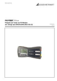
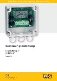
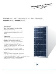
![SCHOTT PROTECT POLY 175-185 data sheet_D[...] - bk solar](https://img.yumpu.com/1309848/1/186x260/schott-protect-poly-175-185-data-sheet-d-bk-solar.jpg?quality=85)