CMBO_Navod_EN_44836 20070219 - Waeco
CMBO_Navod_EN_44836 20070219 - Waeco
CMBO_Navod_EN_44836 20070219 - Waeco

You also want an ePaper? Increase the reach of your titles
YUMPU automatically turns print PDFs into web optimized ePapers that Google loves.
Part No. <strong>44836</strong><br />
Instructions of operation and installation<br />
for<br />
mini-ovens CRAMER<br />
Model <strong>CMBO</strong><br />
Variants: <strong>CMBO</strong>K, <strong>CMBO</strong>A, <strong>CMBO</strong>C, <strong>CMBO</strong>B<br />
<strong>CMBO</strong>D, <strong>CMBO</strong>DS, <strong>CMBO</strong>DSV<br />
<strong>CMBO</strong>GDS, <strong>CMBO</strong>GDSV<br />
<strong>CMBO</strong>GRF/V<br />
GB<br />
GB, IE, IS<br />
Identification No. of product<br />
CE-1015
Important warnings<br />
This device as an appliance of the 3 rd class is intended to be built into a kitchen block.<br />
Oven output (Hs) 1,1 kW (Mn = 80 g/h, propane/butane)<br />
Grill output (Hs) 1,6 kW (Mn = 115 g/h, propane/butane)<br />
(It is ensured and technically impossible that the two burners be turned on at the same<br />
time.)<br />
In case the gas tap may be hardly turned or if it gets jammed, it should be either replaced or the<br />
respective cone of valve should be detached from the valve, cleaned by benzine and lubricated<br />
with special grease for taps, e.g. from the company Klüber, Munich, type „Staburgas No. 32“,<br />
and attached back. This act should be carried out only by an expert in gas appliances.<br />
Installation of the facility may be carried out only by expert workers with appropriate<br />
certificate!<br />
This facility should be installed and connected according to applicable conditions of installation<br />
as <strong>EN</strong> 1949. Special care should be paid to determined measures regarding aeration.<br />
Before connecting the oven, it is necessary to check whether the local conditions for connections<br />
(type of gas and gas pressure) are identical with the setting of the appliance. The type of gas and<br />
the gas pressure for this appliance are indicated on the instruction plate (or the product's name<br />
plate).<br />
Before being put into operation as well as after each 2 years, the parts conducting gas and<br />
connected exhaustion of waste gases (gas exhaust pipe) should be checked by an expert<br />
according to applicable standards, especially to European Standard <strong>EN</strong> 1949.<br />
The user is responsible for ensuring the check. The expert performing the installation of the oven<br />
shall notify him/her of the obligation of check in writing.<br />
The appliance may only be used for the purposes of baking and grilling and under the conditions<br />
specified below. It may be in no case used for other purposes than described in these operating<br />
instructions (e.g. for heating etc.).<br />
The use of the oven may lead to a generation of heat and moisture at the place of installation.<br />
Take care of good aeration of the kitchen: natural aeration openings should be clear or, as the<br />
case may be, it is necessary to provide for a mechanical venting device.<br />
Intense and long-term using of the oven may require additional venting, e.g. opening of the<br />
window or operating of a mechanical venting device on a higher performance level.<br />
The pressure reduction (regulator) used between the gas cylinder and the oven should be of<br />
output 1.5 kg/h:<br />
2
ATT<strong>EN</strong>TION: ACCORDING TO APPLICABLE STANDARDS, THE DEVICE SHOULD<br />
BE INSTALLED BY AN EXPERT.<br />
IMPORTANT: TO AVOID ANY POSSIBLE ACCID<strong>EN</strong>T, IT IS NECESSARY TO<br />
INSTALL THE DEVICE ACCORDING TO THESE INSTRUCTIONS. LOSS OF<br />
WARRANTY IS A CONSEQU<strong>EN</strong>CE OF INEXPERT INSTALLATION<br />
„ANY MODIFICATION TO THE APPLIANCE MAY BE DANGEROUS, AND IS<br />
THEREFORE NOT PERMITTED !“<br />
1. AERATION OF THE ROOM<br />
Every room where one or more appliances are to be installed must have one or more openings<br />
to allow the entry of fresh air. Above the appliance there have to be one or several openings in<br />
order to assure the exhaust of combustion and renewal of fresh air.<br />
These ventilation openings must comply with the requirements of <strong>EN</strong> 1646-1, <strong>EN</strong> 1949 and<br />
<strong>EN</strong> 721.<br />
These openings need to be checked from time to time. If necessary, the user should clean them<br />
(e.g., in wintertime, snow or dirt should be removed from the exhaust output and the<br />
combustion air input).<br />
If the appliance is built-in, safety regulations must be observed, and particularly the European<br />
standard <strong>EN</strong> 1949.<br />
Outlets of waste gases may not be installed at entrance doors and below aeration openings.<br />
When exhaust gases are discharged, the ascending position of all parts needs to be<br />
checked.<br />
2. CONNECTION OF THE OV<strong>EN</strong> TO THE GAS SUPPLY<br />
The connection of gas to the oven may be carried out exclusively with gas-tight connections.<br />
Tubes used to connect the oven should be of zinc-coated iron or copper. These pipes may be<br />
used only with gas-tight connection. Having finished connection works, it is necessary to<br />
check tightness of the connection, using soap solution that is poured on the connection. Soap<br />
solution shows possible leakages by creating bubbles.<br />
ATT<strong>EN</strong>TION: WH<strong>EN</strong> INSTALLING AND CONNECTING THE DEVICE, THE GAS<br />
PIPELINE MAY NOT BE TWISTED, PULLED, NOR OTHERWISEE STRAINED.<br />
3
3. GAS CYLINDERS<br />
It is necessary to use such gas cylinders that are usually sold in the country of sale of the<br />
appliance. Kind of gas used is clearly indicated on the packaging and on an indelible type<br />
plate on the rear side of the oven.<br />
UNSUITABLE OPERATION CONDITIONS OF THE FACILITY MAY BE A<br />
CONSEQU<strong>EN</strong>CE OF USING ANOTHER PRESSURE OR GAS THAN STATED IN<br />
THE INSTRUCTIONS. THEREFORE THE MANUFACTURER DECLINES ANY<br />
LIABILITY IN CONNECTION WITH INEXPERT OPERATION OF THE<br />
APPLIANCE.<br />
In any case, the following instructions shall be adhered to:<br />
Complete gas cylinders with a valve and pressure reduction (regulator) should be placed in<br />
vertical position in a cabinet exclusively intended for that purpose. Access to cylinders must<br />
not be obstructed.<br />
Replacement of gas cylinder should be simple, while it should be possible to carry it out<br />
without any obstacles.<br />
BE SURE TO SHUT THE GAS CYLINDER VALVE AFTER USE.<br />
ATT<strong>EN</strong>TION!<br />
The following safety precautions should be adhered to, when replacing the gas cylinder:<br />
a) close taps of the device (revolving button in the position „0)“;<br />
b) shut the gas tap in the vehicle that is assigned to the appliance.<br />
c) make sure there were no open flames or glowing objects around;<br />
d) close the valve of the cylinder being replaced;<br />
e) detach the pressure reduction (regulator) of the empty gas cylinder, take the gas<br />
cylinder out of the cabinet and replace it with a new one –carry out connection of the<br />
new cylinder in the reverse sequence.<br />
f) dheck tightness, using soap solution, as explained above.<br />
g) Ignite the burner and check whether the oven works properly. If it does not, contact a<br />
specialised engineer.<br />
3.1 CABINET FOR GAS CYLINDERS<br />
A cabinet for gas cylinders should be sufficiently large to accommodate the shown type of<br />
gas cylinder with pressure regulator attached. In Germany, its width and depth may not be<br />
smaller than 325 mm and the height less than 620 mm.<br />
4
4. VISUAL INSPECTION OF FLAME<br />
a) The flame should burn quietly. It should be prevailingly blue, having clear outlines.<br />
b) When the flame is not burning cleanly, there should be checked, whether openings of air<br />
inlet (Venturi tube) are clear. If it is not the case, particles causing obstruction should be<br />
removed.<br />
c) In case of any doubt a gas specialist needs to be consulted.<br />
5. POWER SUPPLY AND ELECTRICAL CONNECTION:<br />
The appliance needs 12 V DC power supply for possible future internal lighting and<br />
electronic stroke spark ignition. For special "Z" models, the stroke spark ignition will be<br />
initiated by a replaceable 1,5 V battery.<br />
ELECTRICAL CONNECTION<br />
To connect the facility, a twin cable of 1.5 mm 2 with red and black colours should be used,<br />
which shall be connected to the terminal placed on the rear side of the device. The poles on<br />
this terminal are indicated + and –. You will recognise the positive pole by red colour. When<br />
connecting the cable, in any case take care of correct poling! Electrical circuit should be fused<br />
with 3 A safety fuse (not delivered with the device).<br />
IN NO CASE THE DEVICE MAY BE CONNECTED TO 230 V MAINS SUPPLY!<br />
THIS WOULD LEAD TO DEFINITE DESTRUCTION OF ELECTRIC PARTS AND<br />
IT WOULD BE ASSOCIATED WITH A HAZARD TO THE CUSTOMER.<br />
6. LEAKAGE OF GAS<br />
When testing leakages of gas, we recommend you to use an electronic gas leak detector with<br />
type approval. In case of a defect, the tap of gas supply must be closed. Contact a gas fitter,<br />
dealer or specialised engineer.<br />
5
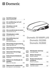
7. INSTALLATION OF THE DEVICE<br />
7.1 ATTACHM<strong>EN</strong>T OF THE DEVICE TO FURNITURE<br />
In order to install the device, there should be created a space of dimensions shown in Figure 1<br />
depending on the respective model of device (look at type plate of the device).<br />
Figure 1<br />
Variant X (Width) Y1/Y2 (Depth) Z (Height)<br />
<strong>CMBO</strong>K 398 458/553 284<br />
<strong>CMBO</strong>A 398 458/553 304<br />
<strong>CMBO</strong>C 484 458/553 284<br />
<strong>CMBO</strong>B 484 458/553 304<br />
<strong>CMBO</strong>DS 524 458/553 354<br />
<strong>CMBO</strong>DSV 524 458/553 354<br />
<strong>CMBO</strong>GDS 524 458/553 354<br />
<strong>CMBO</strong>GDSV 524 458/553 354<br />
<strong>CMBO</strong>GRF/V 438 458/553 410<br />
Y1- according picture 3,4,5<br />
Y2- according picture 6,7<br />
The position of this space may be selected depending on the intended point of installation.<br />
6
Within the built-in furniture, the oven should be placed on a firm, stable platform. The oven<br />
should be fixed on the front side of the built-in furniture, using the attached 4 screws (Figure<br />
2). Gas pipings, taps or parts of burner may not be used for fixing.<br />
Minimum distance from inflammable surfaces on the right and left sides: 20 mm. Minimum<br />
distance from inflammable upper surfaces: 50 mm. Minimum distance of the waste gas<br />
exhaust case from inflammable surfaces: 50 mm.<br />
All walls or constituent parts that are at a smaller than minimum distance from the appliance<br />
should be either lined or protected with non-flammable materials.<br />
Figure 2<br />
7
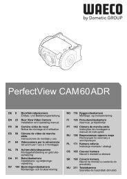
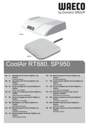
Figure 3<br />
Installation of oven with gas exhaust pipe upward through roof chimney.<br />
Roof chimney Truma, art.No. 30700-03<br />
Ventilation chimney tube Truma O55<br />
atr. No. 39320-00<br />
8<br />
Exhaust box<br />
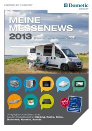
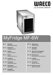
Figure 4<br />
Installation of oven with exhaust of waste gases upward through a chimney across the wall.<br />
Chimney across the wall Truma, art.No. 34011-08<br />
Ventilation chimney tube Truma O55<br />
atr. No. 39320-00<br />
Exhaust box
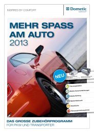
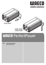
Figure 5<br />
Installation of oven without a chimney exhausting waste gases through front of appliance.<br />
Figure 6<br />
Installation of oven with gas exhaust pipe at the back through roof chimney.<br />
Roof chimney Truma, art.No. 30700-03<br />
Ventilation chimney tube Truma O55<br />
atr. No. 39320-00<br />
9<br />
Exhaust box<br />
Exhaust box
Figure 7<br />
Installation of oven with exhaust of waste gases at the back through a chimney across the wall.<br />
Chimney across the wall Truma, art.No. 34011-08<br />
Ventilation chimney tube Truma O55<br />
atr. No. 39320-00<br />
10<br />
Exhaust box<br />
Exhaust of waste gases through the chimney should be of continuously ascending placing.<br />
Maximum length of waste gas outlet is 2,000 mm. The maximum difference of height between<br />
the upper edge of the oven for baking and the outlet of waste gases is 1,500 mm. For ducting the<br />
exhaust gases over a side wall stack, the minimum elevation difference is 150 mm, and 200 mm<br />
for a Truma roof stack.<br />
Walls and integral parts whose distance from waste gas exhaust pipe is less than 50 mm should<br />
be either lined or protected with materials belonging to the group of fire resistance M0.<br />
At the output from the oven and at the input to the stack extension, the exhaust from the flexible<br />
metallic pipe with a diameter of 55 mm must be attached with a worm hose clamp (a Truma<br />
clamp is convenient for the given 50 – 60 mm pipe), or with the attachment screw supplied<br />
along with the Truma roof stack.<br />
THE DEVICE SHOULD BE PLACED OUT OF REACH OF EASILY INFLAMMABLE<br />
MATERIALS.<br />
7.2 PROTECTION FROM OVERHEATING<br />
All conditions for installation of the facility described under the point 7.1. are necessary to be<br />
adhered to.
7.3 TAKING THE DEVICE OUT OF FURNITURE<br />
a) Close the main gas valve.<br />
b) Loosen fixing screws.<br />
c) Loosen gas connection and possible electrical cables.<br />
8. USE THE DEVICE ONLY IN A WELL AERATED ROOM<br />
During operation of the appliance, the aeration openings have to be clear.<br />
9. USING THE OV<strong>EN</strong><br />
ATT<strong>EN</strong>TION: please push up the lock handle with thumb to open the door. At shutting of the<br />
door the handle locks door automatically.<br />
9.1 IGNITION OF THE OV<strong>EN</strong><br />
The oven is equipped with an electronic stroke spark ignition system.<br />
a) To light the oven or the grill, the door of the oven must be fully open.<br />
b) Press the turn button lightly and turn it to the left to the ignition position. The oven may<br />
be lit at any position of the turn button. After igniting flame, still hold the button pressed<br />
for the time of about 10 seconds. The lighting of the grill (for an oven with grill) can be<br />
done with the turn button at its "Grill" position (the button turned to the right after<br />
pressing).<br />
c) Release the button and turn it to the desired position.<br />
The oven is equipped with an automatic thermostat.<br />
Various settings of the revolving button correspond to temperatures within the range up to 250<br />
o C.<br />
In case of an excessive deviation of temperature of the oven, the thermostat should be<br />
repaired.<br />
IMPORTANT: In case ignition does not succeed, repeat the procedure from the beginning. If<br />
necessary, you should check, whether gas supply is not missing in the device or, as the case<br />
may be, electric power. If the device would not work despite that, close the tap of gas inlet<br />
and contact your dealer. Before putting into operation for the first time the oven should be left<br />
baking idle (without any foodstuffs) for the time of approximately ½ an hour at the highest<br />
temperature. In case the burner goes out unintentionally, turn off the knob and, before turning<br />
on again, let the burner be switched off for the time of 1 minute at least.<br />
„GLOVES ARE NECESSARY TO BE USED UPON HANDLING HOT OBJECTS.“<br />
11
9.2. OPERATION OF OV<strong>EN</strong><br />
a) The pan should be pushed in the guiding rail.<br />
b) The position of pan may be chosen out of three vertical positions.<br />
ATT<strong>EN</strong>TION: When being used, the oven attains high temperatures. Avoid<br />
presence of children in its vicinity.<br />
9.3 OPERATION OF GRILL (for appliances with the grill function only)<br />
a) Light the grill burner with the door fully open.<br />
b) When grilling, the door of the oven must be open.<br />
ATT<strong>EN</strong>TION: When being used, the oven attains high temperatures. Avoid<br />
presence of children in its vicinity.<br />
10. FAULTS OF THE FACILITY<br />
Upon faults of the facility, contact a specialised expert.<br />
INSTRUCTIONS FOR CLEANING<br />
Exclusively non-aggressive cleaning agents for households may be used for cleaning. In no<br />
case, agents for scrubbing and bleaching may be used.<br />
DOMETIC SLOVAKIA SR s. r. o.<br />
● Tehelná 8 ● SK – 986 01 Fiľakovo ●<br />
● Phone: +421-47 4319100 ●<br />
● Fax: +421-47 4319144, 4319166 ●<br />
● E-mail: dometic@dometic.sk ●<br />
● Internet: www.dometic.sk ●<br />
12
T.Nr. 43955<br />
Bedienungs- und Installationsanweisung<br />
für<br />
CRAMER Mini-Backofen<br />
Modell <strong>CMBO</strong><br />
Varianten: <strong>CMBO</strong>K, <strong>CMBO</strong>A, <strong>CMBO</strong>C, <strong>CMBO</strong>B,<br />
<strong>CMBO</strong>D, <strong>CMBO</strong>DS, <strong>CMBO</strong>DSV<br />
<strong>CMBO</strong>GDS, <strong>CMBO</strong>GDSV<br />
<strong>CMBO</strong>GRF/V<br />
D<br />
DE, AT, CH<br />
Produkt-ID-Nummer<br />
CE-1015
Wichtige Hinweise<br />
Dieses Gerät ist als ein Gerät der Klasse 3 zum Einbau in einen Küchenblock bestimmt.<br />
Leistung des Backofens (Hs) 1,1 kW (Mn = 80 g/h, Propan/Butan)<br />
Leistung des Grills (Hs) 1,6 kW (Mn = 115 g/h, Propan/Butan)<br />
(technisch ist sichergestellt, dass beide Brenner nicht gleichzeitig eingeschaltet sein<br />
können)<br />
Sollte der Gashahn schwergängig sein oder klemmen, so ist dieser entweder auszuwechseln<br />
oder das entsprechende Hahnküken aus dem Hahngehäuse auszubauen, in Waschbenzin zu<br />
reinigen mit einem speziellen Hahnfett z. B. der Fa. Klüber, München, Typ „Staburgas Nr.<br />
32“ zu fetten und wieder einzubauen. Diese Arbeit darf nur von einem Gasfachmann<br />
ausgeführt werden.<br />
Die Installation des Gerätes darf nur von dafür zugelassenem Fachpersonal<br />
durchgeführt werden ! Neben den üblichen Vorschriften muss besonders die Norm <strong>EN</strong><br />
1949 beachtet werden !<br />
Dieses Gerät muss nach den geltenden Installationsbedingungen aufgestellt und<br />
angeschlossen werden. Besonders zu beachten sind geeignete Belüftungsmaßnahmen.<br />
Vor Anschluss des Gerätes muss geprüft werden, ob die örtlichen Anschlussbedingungen<br />
(Gasart und Gasdruck) und die Geräteeinstellung übereinstimmen. Die Gasart und der<br />
Gasdruck für dieses Gerät sind auf einem Hinweisschild (oder auf dem Geräteschild)<br />
angegeben.<br />
Gasführende Teile und die angeschlossenen Abgasabführungen (Abgasrohr) sind vor der<br />
ersten Inbetriebnahme sowie nach Ablauf von jeweils 2 Jahren nach den geltenden Normen<br />
(in Deutschland nach dem DVGW-Arbeitsblatt G 607 und G 608) von einem Sachkundigen<br />
zu überprüfen, insbesondere nach <strong>EN</strong> 1949.<br />
Für die Veranlassung der Prüfung ist der Betreiber verantwortlich. Es ist durch den Einrichter<br />
der Anlage auf die Prüfpflicht schriftlich hinzuweisen.<br />
Das Gerät darf nur für Backen und Grillen unter den im Weiteren angegebenen Bedingungen<br />
genutzt werden. Es darf auf keinen Fall für andere als in dieser Anleitung beschriebene<br />
Zwecke benutzt werden (z.B. Heizen, usw.).<br />
Die Benutzung des Gerätes kann zu einer Wärme- bzw. Feuchtigkeitsbildung im<br />
Aufstellungsraum führen. Auf gute Belüftung der Küche achten: die natürlichen<br />
Belüftungsöffnungen offen halten oder eine mechanische Lüftungseinrichtung vorsehen.<br />
Eine intensive und langandauernde Benutzung des Gerätes kann eine zusätzliche Belüftung, z.<br />
B. Öffnen eines Fensters oder den Betrieb der mechanischen Lüftungseinrichtung auf höherer<br />
Leistungsstufe, erforderlich machen.<br />
Der zwischen Gasflasche und Gerät anzuwendende Druckreduzierer (Regler) muss eine<br />
Leistung von 1,5 kg/h haben:<br />
2
ACHTUNG: DAS GERÄT MUß GEMÄß D<strong>EN</strong> GÜLTIG<strong>EN</strong> NORM<strong>EN</strong> (<strong>EN</strong> 1949) VON<br />
EINEM FACHMANN EINGEBAUT WERD<strong>EN</strong>.<br />
WICHTIG: ZUR VERMEIDUNG JEDES MÖGLICH<strong>EN</strong> UNFALLS IST ES NÖTIG,<br />
DASS DAS GERÄT LAUT VORLIEG<strong>EN</strong>D<strong>EN</strong> ANWEISUNG<strong>EN</strong> INSTALLIERT<br />
WIRD. UNSACHGEMÄSSE INSTALLATION HAT D<strong>EN</strong> VERLUST DER<br />
GARANTIE ZUR FOLGE.<br />
„JEDE ÄNDERUNG DES GERÄTES KANN GEFÄHRLICH SEIN UND IST NICHT<br />
GESTATTET!“<br />
1. BELÜFTUNG DES RAUMS<br />
Jeder Raum, in dem ein oder mehrere Geräte installiert werden sollen, muss eine oder<br />
mehrere Öffnungen haben, die den Eintritt von Frischluft ermöglichen. Über dem Gerät<br />
müssen eine oder mehrere Lüftungsöffnungen sein, um genügende Entsorgung der<br />
Verbrennungsprodukte und Erneuerung der Luft für die Benutzer sicherzustellen.<br />
Diese Lüftungsöffnungen müssen den Anforderungen der Normen <strong>EN</strong> 1949, <strong>EN</strong> 1646-1<br />
und <strong>EN</strong> 721 entsprechen.<br />
Diese Öffnungen sind von Zeit zu Zeit zu kontrollieren und gegebenenfalls durch den<br />
Benutzer zu reinigen (z. B. im Winter Abgasaustritt und Verbrennungslufteintritt von<br />
Schnee oder von Schneematsch befreien).<br />
Beim Einbau des Gasgerätes sind geltende Vorschriften, besonders die Norm <strong>EN</strong> 1949 (in<br />
Deutschland auch die Regeln des DVGW-Arbeitsblattes G 607 (Fahrzeuge) bzw. G 608<br />
(Boote)) zu beachten.<br />
Die Abgasaustritte dürfen nicht bei der Eingangstür und unter den Lüftungsöffnungen<br />
installiert werden.<br />
Bei der Abgasabführung ist insbesondere auf eine in allen Teilen steigende Verlegung<br />
hin zu achten.<br />
2. ANSCHLUSS DES GERÄTES AN DIE GASVERSORGUNG<br />
Der Anschluss der Gasleitungen an das Gerät darf ausschließlich mit gasdichten<br />
Anschlussstücken vorgenommen werden.<br />
Bei Verwendung von Rohren zum Anschluss des Gerätes sollen diese aus verzinktem<br />
Eisen oder aus Kupfer sein. Diese Rohrleitungen können mit einem gasdichten Anschluss<br />
verwendet werden. Nach Beendigung der Anschlussarbeiten soll die Dichtigkeit der<br />
Gasleitungen mittels einer Seifenlösung, die auf die Anschlussstellen gegossen wird,<br />
überprüft werden; die Seifenlösung zeigt eventuelle Undichtigkeiten durch<br />
Bläschenbildung an.<br />
ACHTUNG: BEIM INSTALLIER<strong>EN</strong> UND ANSCHLIEß<strong>EN</strong> DES GERÄTES DARF<br />
DAS GASROHR NICHT GEDREHT, GEZOG<strong>EN</strong> ODER ANDERS VERSPANNT<br />
WERD<strong>EN</strong>.<br />
3
3. GASFLASCH<strong>EN</strong><br />
Es sind diejenigen Gasflaschen zu verwenden, die in dem Land, in dem das Gerät verkauft<br />
wird, im Handel üblich sind. Die zu verwendende Gasart ist klar auf der Verpackung und<br />
auf dem löschsicheren Typenschild auf der Rückseite des Gerätes angezeigt.<br />
DIE VERW<strong>EN</strong>DUNG EINES VON D<strong>EN</strong> VORSCHRIFT<strong>EN</strong> ABWEICH<strong>EN</strong>D<strong>EN</strong><br />
DRUCKES ODER GASES KANN UNREGELMÄSSIGE<br />
BETRIEBSVERHÄLTNISSE DES GERÄTES HERVORRUFF<strong>EN</strong>; DER<br />
HERSTELLER LEHNT DESHALB JEDE VERANTWORTUNG IM<br />
ZUSAMM<strong>EN</strong>HANG MIT UNSACHGEMÄSSER BEDI<strong>EN</strong>UNG DES GERÄTES<br />
AB.<br />
Es müssen auf jeden Fall folgende Anweisungen befolgt werden:<br />
Die Gasflaschen, komplett mit Ventil und Druckreduzierer (Regler), müssen senkrecht in<br />
dem eigens dafür vorgesehenen Schrank aufgestellt werden; der Zugang zu den Flaschen<br />
darf nicht verstellt sein.<br />
Der Austausch der Gasflasche muss leicht und ohne Hindernisse durchführbar sein.<br />
NACH GEBRAUCH SOLL DAS V<strong>EN</strong>TIL DER GASFLASCHE ZUGEDREHT<br />
WERD<strong>EN</strong>.<br />
ACHTUNG!<br />
Beim Austausch der Gasflasche müssen folgende Vorsichtsmassnahmen getroffen werden:<br />
a) Hähne des Gerätes schließen ( Drehknebel auf 0 – Position ).<br />
b) Das dem Gerät im Fahrzeug zugeordnete Absperrventil schließen.<br />
c) Man versichere sich, dass sich in der Nähe keine Flamme oder glühenden<br />
Gegenstände befinden;<br />
d) Ventil der auszutauschenden Gasflasche schließen;<br />
e) Den Druckreduzierer (Regler) der leeren Gasflasche abschrauben, letztere aus dem<br />
Schrank herausnehmen und durch eine neue Gasflasche ersetzen – in umgekehrter<br />
Reihenfolge vorgehen für den Anschluss der neuen Flasche.<br />
f) Dichtigkeit mittels Seifenlösung wie oben beschrieben testen.<br />
g) Brenner anzünden und ordnungsgemäßen Betrieb überprüfen; im gegenteiligen Fall<br />
wende man sich an einen spezialisierten Techniker.<br />
3.1 GASFLASCH<strong>EN</strong>SCHRANK<br />
Der Schrank für die Gasflaschen muß ausreichend groß sein, um den angegebenem<br />
Gasflaschentyp mit dem montierten Druckregler aufzunehmen. Er darf in Deutschland<br />
325 mm Breite und Tiefe und 620 mm Höhe nicht unterschreiten.<br />
4
4. SICHTKONTROLLE DER FLAMME<br />
a) die Flamme muss ruhig brennen. Sie muss überwiegend blau sein und klare Umrisse<br />
haben.<br />
b) Wenn die Flamme unsauber brennt, ist zu prüfen, ob die Zuluftöffnungen<br />
(Venturirohr) frei sind. Im gegenteiligen Fall müssen verstopfende Teile entfernt<br />
werden.<br />
c) Im Zweifel ist ein Gasfachmann hinzuzuziehen.<br />
5. STROMVERSORGUNG UND ELEKTRISCHER ANSCHLUSS:<br />
Das Gerät benötigt 12 Volt Gleichstrom für die eventuelle Innenbeleuchtung und die<br />
elektronische Taktfunkenzündung. Bei den Sondermodellen “Z” wird die<br />
Taktfunkenzündung mit einer auswechselbaren 1,5 Volt Batterie betrieben.<br />
ELEKTRISCHER ANSCHLUSS<br />
Für den Anschluss des Gerätes soll ein zweiadriges, 1,5 mm 2 rotes und schwarzes Kabel,<br />
das an die auf der Hinterseite des Gerätes befindliche Klemme angeschlossen wird,<br />
verwendet werden. An dieser Klemme sind die beiden Pole mit + und – gekennzeichnet.<br />
Der positive Pol ist an der roten Farbe erkenntlich. Beim Anschluss der Kabel unbedingt<br />
auf richtige Polung achten! Der Stromkreis muss mit einer 3 A Schmelzsicherung (wird<br />
nicht mitgeliefert) abgesichert werden.<br />
DAS GERÄT DARF AUF KEIN<strong>EN</strong> FALL AN DAS 230 VOLT NETZ<br />
ANGESCHLOSS<strong>EN</strong> WERD<strong>EN</strong>! DIES HÄTTE DIE <strong>EN</strong>DGÜLTIGE<br />
ZERSTÖRUNG DER ELEKTRISCH<strong>EN</strong> ELEM<strong>EN</strong>TE ZUR FOLGE UND WÄRE<br />
MIT GEFAHR FÜR D<strong>EN</strong> VERBRAUCHER VERBUND<strong>EN</strong>.<br />
6. GASUNDICHTIGKEIT<br />
Bei der Gasdichtheitsprüfung empfehlen wir die Verwendung eines elektronischen,<br />
typgeprüften Gasdetektors. Bei Störung muss der Hahn des Gasversorgungsnetzes<br />
geschlossen werden; man wende sich an einen Installateur, Händler oder spezialisierten<br />
Techniker.<br />
5
7. MONTAGE DES GERÄTES<br />
7.1 BEFESTIGUNG DES GERÄTES AM MÖBEL<br />
Für den Einbau des Gerätes muss je nach Gerätemodell ( siehe Typenschild am Gerät ) ein<br />
freier Raum mit den auf Abb.1 angegebenen Massen geschaffen werden.<br />
Abb.1<br />
Variante X (Breite) Y1/Y2 (Tiefe) Z (Höhe)<br />
<strong>CMBO</strong>K 398 458/553 284<br />
<strong>CMBO</strong>A 398 458/553 304<br />
<strong>CMBO</strong>C 484 458/553 284<br />
<strong>CMBO</strong>B 484 458/553 304<br />
<strong>CMBO</strong>DS 524 458/553 354<br />
<strong>CMBO</strong>DSV 524 458/553 354<br />
<strong>CMBO</strong>GDS 524 458/553 354<br />
<strong>CMBO</strong>GDSV 524 458/553 354<br />
<strong>CMBO</strong>GRF/V 438 458/553 410<br />
Y1- nach der Abb. 3,4,5<br />
Y2- nach der Abb. 6,7<br />
Die Lage dieses Raums kann je nach Installationswunsch gewählt werden.<br />
Im Einbaumöbel muss das Gerät auf einer festen, stabilen Unterlage stehen. Das Gerät<br />
muss fest an der Vorderseite des Einbaumöbels mit Hilfe der 4 mitgelieferten Schrauben<br />
befestigt werden (Abb. 2). Es dürfen zur Befestigung nicht die Gasleitungen, Hähne oder<br />
Teile des Brenners benutzt werden.<br />
6
Mindestabstand seitlich rechts und links zu brennbaren Flächen: 20 mm. Mindestabstand<br />
zu brennbaren Flächen nach oben: 50 mm. Mindestabstand Abgasführungskasten zu<br />
brennbaren Flächen: 50 mm.<br />
Alle Wände oder Elemente, die weniger als den Mindestabstand zum Gerät haben, müssen<br />
mit nicht brennbaren Materialen entweder verkleidet oder geschützt werden.<br />
Abb.2<br />
Abb.3<br />
Einbausituation für Backofen mit Abgasführung oben mit Dachkamin.<br />
7
Truma Dachkamin Art.Nr. 30700-03<br />
Abluft<br />
Truma Kaminrohr O55<br />
Art.Nr. 39320-00<br />
Abb.4<br />
Einbausituation für Backofen mit Abgasführung oben mit Wandkamin.<br />
Truma Wandkamin Art.Nr. 34011-08<br />
Abluft Truma Kaminrohr O55<br />
Art.Nr. 39320-00<br />
8<br />
Abgasführungskasten<br />
Abgasführungskasten<br />
Abb.5<br />
Einbausituation für Backofen ohne Schornstein mit Abgasführung durch die Frontblende.
9<br />
Abgasführungskasten
Abb.6<br />
Einbausituation für Backofen mit Abgasführung hinten mit Dachkamin<br />
Truma Dachkamin Art.Nr. 30700-03<br />
10<br />
Abluft Truma Kaminrohr O55<br />
Art.Nr. 39320-00<br />
Abgasführungskasten<br />
Abb.7<br />
Einbausituation für Backofen mit Abgasführung hinten mit Wandkamin<br />
Truma Wandkamin Art.Nr. 34011-08<br />
Abluft Truma Kaminrohr O55<br />
Art.Nr. 39320-00<br />
Abgasführungskasten
Die Verbrennungsgasabführung durch ein Kaminrohr muss durchgehend steigend verlegt<br />
sein. Die maximale Länge der Verbrennungsgasabführung beträgt 2000 mm. Der maximale<br />
Höhenunterschied zwischen Oberkante Backofen und Abgasaustritt am Kamin ist 1500<br />
mm. Der minimale Höhenunterschied ist 150 mm bei Abluftführung durch<br />
Seitenwandkamin und 200 mm bei Abluftführung durch Truma-Dachkamin.<br />
Die Wände und Elemente, die sich zu der Verbrennungsgasabführung näher als 50 mm<br />
befinden, müssen mit zu der Feuerbeständigkeitsgruppe M0 gehörenden Materialen<br />
entweder verkleidet oder geschützt werden.<br />
Die Verbrennungsgasabführung aus flexiblem Metallrohr ∅ 55 mm muss am Austritt vom<br />
Backofen sowie beim Eintritt in den Kaminaufsatz durch jeweils eine<br />
Schneckengewindeschelle (Truma – Schelle passend zum Rohr ∅ 50 – ∅ 60 mm) bzw.<br />
durch mit dem Truma-Dachkamin gelieferte Befestigungsschrauben befestigt werden.<br />
DAS GERÄT MUSS <strong>EN</strong>TFERNT VON LEICHT<strong>EN</strong>TZÜNDLICH<strong>EN</strong><br />
MATERIAL<strong>EN</strong> AUFGESTELLT WERD<strong>EN</strong>.<br />
7.2 SCHUTZ GEG<strong>EN</strong> ÜBERHITZUNG<br />
Es müssen alle unter dem Punkt 7 beschriebenen Bedingungen für Einbau des Gerätes<br />
eingehalten werden.<br />
7.3 HERAUSNEHM<strong>EN</strong> DES GERÄTES AUS DEM MÖBEL<br />
a) Gashahn am Gerät schließen<br />
b) Absperrventil schließen<br />
c) Ventil der auszutauschenden Gasflasche schließen<br />
d) Befestigungsschrauben lösen<br />
e) Gasanschluss und eventuelle elektrische Kabel lösen.<br />
8. B<strong>EN</strong>UTZ<strong>EN</strong> SIE DAS GERÄT NUR IN EINEM GUT BELÜFTET<strong>EN</strong> RAUM<br />
Ist das Gerät in Betrieb, sind die Lüftungsöffnungen frei zu halten.<br />
11
9. B<strong>EN</strong>UTZ<strong>EN</strong> DES GERÄTES<br />
9.1 ANZÜND<strong>EN</strong> DES GERÄTES<br />
Der Backofen ist mit einer elektronischen Taktfunkenzündung ausgerüstet.<br />
a) Zum Anzünden des Backofens oder Grills muss die Backofentür vollkommen offen<br />
sein.<br />
b) Drehknopf leicht hineindrücken und durch Linksdrehen auf Zündstellung drehen. Die<br />
Zündung des Backofens ist möglich bei allen Drehknopfpositionen. Nachdem der<br />
Brenner gezündet hat, den Drehknopf ca. 10 Sekunden gedrückt halten bis zum<br />
Ansprechen der Zündsicherung.<br />
Die Zündung des Grills ( beim Ofen mit Grill ) ist möglich auf der Drehknopfposition<br />
Grill-(Rechtsdrehen des Drehknopfes nach dem Eindrücken).<br />
c) Drehknopf loslassen und auf die gewünschte Einstellung drehen.<br />
Der Backofen ist mit einem automatischen Thermostaten ausgerüstet. Die verschiedenen<br />
Einstellungen des Drehknopfes entsprechen den Temperaturen im Bereich bis zu 250 o C.<br />
Wenn eine übermäßige Abweichung der Backofentemperatur festgestellt wird, ist eine<br />
Reparatur des Thermostaten zu veranlassen.<br />
WICHTIG Falls das Anzünden erfolglos ist, wiederhole man den Vorgang von Anfang<br />
an; im Bedarfsfall sollte man überprüfen lassen, ob Gas und/oder Strom im Gerät fehlen.<br />
Sollte das Gerät dennoch nicht funktionieren, schließe man den Gaszufuhrhahn und wende<br />
sich an den Händler. Vor der ersten Inbetriebnahme des Backofens, soll dieser leer (ohne<br />
Lebensmittel) für die Dauer von ca. ½ Stunde bei Höchsttemperatur laufen. In dem Fall,<br />
dass die Brennerflamme versehentlich gelöscht wird, drehen Sie den Brennerregler zu und<br />
lassen den Brenner für mindestens 1 Minute ausgeschaltet, bevor Sie ihn wieder zünden.<br />
12
„FÜR DIE HANDHABUNG HEISSER GEG<strong>EN</strong>STÄNDE SOLL<strong>EN</strong> HAND-<br />
SCHUHE B<strong>EN</strong>UTZT WERD<strong>EN</strong>“<br />
9.2. BEDI<strong>EN</strong>UNG DES BACKOF<strong>EN</strong>S<br />
a) Die Pfanne bzw. das Rost muss in die Führungsschiene eingeschoben werden.<br />
b) Die Position kann in drei Höhenpositionen gewählt werden.<br />
ACHTUNG: Gerät erreicht im Betriebszustand hohe Temperaturen. Kinder<br />
fernhalten !<br />
9.3. BEDI<strong>EN</strong>UNG DES GRILLS (nur für Geräte mit Grillfunktion).<br />
a) Den Grillbrenner anzünden bei vollständig geöffneter Tür.<br />
b) Die Backofentür beim Betrieb des Grills offen lassen.<br />
ACHTUNG: Gerät erreicht im Betriebszustand hohe Temperaturen. Kinder<br />
fernhalten !<br />
10. STÖRUNG<strong>EN</strong> AM GERÄT<br />
Bei Störungen am Gerät wende man sich an einen spezialisierten Fachmann.<br />
ANWEISUNG<strong>EN</strong> FÜR DIE REINIGUNG<br />
Zur Reinigung dürfen ausschließlich milde Haushaltsreiniger verwendet werden. Auf<br />
keinen Fall dürfen scheuernde oder bleichende Mittel verwendet werden.<br />
DOMETIC CRAMER SR s. r. o.<br />
● Tehelná 8 ● SK – 986 01 Fiľakovo ●<br />
● Telefon: +421-47 4319100 ●<br />
● Fax: +421-47 4319144, 4319166 ●<br />
● E-mail: dometic@dometic.sk ●<br />
● Internet: www.dometic.sk ●<br />
13
La pièce numéro 48599<br />
Mode d’emploi et d’installation<br />
pour<br />
les minifours CRAMER<br />
Modèle <strong>CMBO</strong><br />
Variantes: <strong>CMBO</strong>K, <strong>CMBO</strong>A, <strong>CMBO</strong>C, <strong>CMBO</strong>B,<br />
<strong>CMBO</strong>D, <strong>CMBO</strong>DS, <strong>CMBO</strong>DSV<br />
<strong>CMBO</strong>GDS, <strong>CMBO</strong>GDSV,<br />
<strong>CMBO</strong>GRF/V<br />
F<br />
FR<br />
No d’identification du produit<br />
CE-1015
Avertissments importants<br />
Le présent fourneau est destiné à être intégré dans le bloc-cuisine comme appareil de la classe<br />
3.<br />
Puissance du four est de (Hs) 1,1 kW (Mn = 80 g/h, propane/butane)<br />
Puissance du gril (Hs) 1,6 kW (Mn = 115 g/h, propane/butane)<br />
(Il est techniquement assuré qu'on ne puisse pas allumer parallèlement les deux becs.)<br />
Dans le cas où le robinet à gaz se tourne difficilement ou il paraît d’être enfoncé, il est<br />
nécessaire de remplacer ou démonter le noix de robinet du corps du robinet, de le nettoyer à<br />
l’aide de l’essence technique et d’y appliquer la graisse spéciale destinée aux robinets, par<br />
exemple la graisse produite par l’entreprise Klüber, München, de type "Staburgas n o 32", et de<br />
le remonter enfin. La présente intervention ne peut être opérée que par un professionnel<br />
qualifié.<br />
Le montage de l’installation ne peut être réalisée que par des professionnnels qualifiés,<br />
titulaires d’une attestation spéciale!<br />
Cet appareil doit être monté et raccordé dans les conditions d’installation prévues. Il faut<br />
respecter, en particulier, les mesures concernant l’aération.<br />
Avant de procéder au raccordement du four, il est nécessaire de contrôler si les conditions de<br />
raccordement locales (le type du gaz et la pression du gaz) ainsi que le réglage du four sont<br />
conformes. Le type du gaz et la pression du gaz pour cet appareil sont indiqués sur la plaque<br />
des instructions (ou sur l'étiquette de l'appareil).<br />
Les parties amenant le gaz et raccordées au conduit des produits de la combustion (la<br />
tuyaterie pour évacuer les produits de la combustion) doivent être contrôlées avant la<br />
première mise en service, ainsi que toutes les deux années, par un professionnel selon les<br />
normes applicables, specialement selon la Norme Européenne <strong>EN</strong> 1949.<br />
C’est l’utilisateur qui assume la responsabilité de l’exécution de l’essai. Le professionnel<br />
réalisant le montage doit informer l’utilisateur de l’obligation appartenant à ce dernier de faire<br />
réaliser l’essai.<br />
L'appareil ne peut être utilisé qu'à la cuisson ou à la grillade dans les conditions spécifiées cidessous.<br />
En tout cas, il ne peut pas être utilisé à des fins autres que celles décrites dans le<br />
présent mode d’emploi (par exemple pour le chauffage, etc...).<br />
L’utilisation de l’appareil peut entraîner la création de la chaleur et de l’humidité dans le lieu<br />
de l’installation du four. A cet égard, il est nécesssaire d’assurer la bonne aération de la<br />
cuisine: les trous d’aération naturels doivents être libres, ou bien il faut assurer la ventilation<br />
mécanique.<br />
L’utilisation intensive et à long terme peut être exiger une aération supplémentaire, par<br />
exemple l’ouverture des fenêtres ou la mise en service du dispositif de ventilation d’un niveau<br />
de développement plus avancé.<br />
La capacité du détandeur assurant la réduction (régulateur) de la pression entre la bouteille de<br />
butane et l’appareil doit être de 1,5 kg/h:<br />
2
ATT<strong>EN</strong>TION: L’APPAREIL DOIT ETRE MONTE CONFORMEM<strong>EN</strong>T AUX<br />
NORMES APPLICABLES PAR UN PROFESSIONNEL SELON LA NORME <strong>EN</strong><br />
1949.<br />
IMPORTANT: POUR EMPECHER N’IMPORTE QUEL ACCID<strong>EN</strong>T IL EST<br />
NECESSAIRE D’INSTALLER L’APPAREIL SELON CES INSTRUCTIONS. UNE<br />
INSTALLATION PAR UNE PERSONNE AUTRE QUE PROFESSIONNEL PEUT<br />
<strong>EN</strong>TRAINER LA PERTE DE GARANTIE.<br />
„CHAQUE ADAPTATION DE L'APPAREIL PEUT ETRE DANGEREUSE ET EST<br />
INTERDITE ! “<br />
1. AERATION DE LA CHAMBRE<br />
Chaque espace dans lequel il est installé 1 ou plusieurs appareils doit avoir plusieurs trous<br />
qui permettent la sortie de l’air frais. Au dessus de l’appareil doit être 1 ou plusieurs trous<br />
de ventilation pour assuer la sortie des gaz brûlés et l’arrivée de l’air frais. Ces trous de<br />
ventilation doivent convenir aux normes suivantes <strong>EN</strong> 1949, <strong>EN</strong> 1646-1 et <strong>EN</strong> 721.<br />
Ces trous doivent être contrôlés de temps en temps et en cas de nécessité doivent être<br />
nettoyés par l'utilistauer (par exemple en hiver, il faut éliminer la neige ou de la saleté la<br />
sortie des fumées et de l'entrée de l'air de combustion).<br />
En cas d'encastrement de l'appareil il faut respecter les prescriptions en vigueur,<br />
notamment la Norme européenne <strong>EN</strong> 1949.<br />
Les sorties des produits de la combustion ne doivent pas être installées près de la porte<br />
d’entrée et au-dessous des trous d’aération.<br />
Lors de l'évacuation des fumées il faut contrôler notamment la pose montante de<br />
toutes les parties.<br />
2. RACCORDEM<strong>EN</strong>T DE L’APPAREIL AU GAZ<br />
Le raccordement des conduits de gaz à l’appareil d’utilisation peut être opéré<br />
exclusivement avec des raccords au gaz.<br />
Pour le raccordement de l’appareil il faut utiliser les tubes en fer zingué ou en cuivre. Ces<br />
tuyaux peuvent être posés avec un raccord étanche au gaz. Après l’achèvement des travaux<br />
de raccordement, il est nécessaire de contrôler l’étanchéité des tuyaux de gaz à l’aide de la<br />
solution de savon qui est versé sur les points de raccordement. En cas d’absence<br />
d’étanchéité, la solution de savon créera des bulles.<br />
ATT<strong>EN</strong>TION: LORS DE L’INSTALLATION ET LE RACCORDEM<strong>EN</strong>T DE<br />
L’APPAREIL, LE TUYAU DE GAZ NE DOIT PAS ETRE TORDU, TIRE OU<br />
T<strong>EN</strong>DU.<br />
3
3. BOUTEILLES DE BUTANE<br />
Il faut utiliser les bouteilles de butane accessibles dans le pays de vente de l’appareil. Le<br />
type de gaz utilisé est indiqué clairement sur l’emballage sur la plaque de constructeur<br />
ineffaçable, se trouvant sur le côté derrière de l’appareil.<br />
L’UTILISATION D’UNE PRESSION OU GAZ AUTRES QUE CEUX PREVUS<br />
PAR LES NORMES PEUT CAUSER LES CONDITIONS DE SERVICE DE<br />
L’APPAREIL NON APPROPRIEES. C’EST POURQUOI LE CONSTRUCTEUR<br />
DECLINE TOUTE RESPONSABILITE DU DOMMAGE CAUSE PAR UNE<br />
INTERV<strong>EN</strong>TION NON PROFESSIONNELLE SUR L’APPAREIL.<br />
En tou cas, il est nécessaire de respecter les instructions suivantes:<br />
Les bouteilles de butane complètes munies d’une soupape et du réducteur (régulateur) de la<br />
pression doivent être posées verticalement dans l’armoire destinée uniquement à cette fin.<br />
L’accès aux bouteilles ne doit pas être barré.<br />
Le remplacement de la bouteille de butane doit être facile et réalisable sans entraves.<br />
APRES L'USAGE IL FAUT FERMER LA SOUPAPE DE LA BOUTEILLE A GAZ.<br />
ATT<strong>EN</strong>TION!<br />
En remplaçant la bouteille de butane, il est nécessaire de respecter les mesures de sécurité<br />
suivantes:<br />
a) fermer les robinets de l’appareil (bouton tournant dans la position 0);<br />
b) fermez le robinet d'arrêt qui est dans le véhicule destiné à l'appareil.<br />
c) assurer qu’il ne se trouve à sa proximité aucun feu ou objets brûlants;<br />
d) fermer la soupape de la bouteille de butane à remplacer;<br />
e) démonter la bouteilles (régulateur) de butane vide, la retirer de l’armoire et la<br />
remplacer par une nouvelle bouteille – le raccordement de la nouvelle bouteille doit<br />
être fait dans l’ordre inverse.<br />
f) Contrôler l’étanchéité à l’aide d’une solution de savon par la procédure décrite<br />
ci-dessus.<br />
g) Allumer le brûleur et vérifier le bon fonctionnement de l’appareil. Si l’appareil ne<br />
fonctionne pas bien, il faut s’adresser à un professionnel.<br />
3.1 ARMOIRE POUR LES BOUTEILLES DE BUTANE<br />
L’armoire pour les bouteilles de butane doit être suffisamment grande pour pouvoir<br />
contenir le type défini de la bouteille de butane munie d’un régulateur de la pression. En<br />
Allemange, la largeur et la profondeur de la bouteille de butane ne peuvent pas être<br />
inférieures à 325 mm et la hauteur ne peut pas excéder 620 mm.<br />
4
4. CONTROLE VISUEL DE LA FLAMME<br />
a) La flamme doit brûler tranquillement. Elle doit être majoritairement bleue et doit avoir<br />
des contours clairs.<br />
b) Lorsque la flamme brûle d’une manière malpropre, il est nécessaire de contrôler si les<br />
trous pour l’amenée de l’air (tube Venturi) sont libres. Sinon, il faut éliminer les corps<br />
causant l’engorgement.<br />
c) En cas de problème il faut faire venir un professionnel spécialisé en gaz.<br />
5. ALIM<strong>EN</strong>TATION <strong>EN</strong> COURANT ELECTRIQUE ET LE RACCORD<br />
ELECTRIQUE:<br />
L'appareil exige le courant continu de 12 V pour une éventuelle éclairage intérieure et<br />
l'allumage par bougies de temps électronique. Pour les modèles spécifiques "Z",<br />
l'allumage par bougies de temps sera assurée par une batterie de 1,5 V échangeable.<br />
RACCORD ELECTRIQUE<br />
Pour raccorder l’appareil, il est nécessaire d’utiliser un câble double de 1,5 mm 2 , rouge et<br />
noir, qui se reliera à la borne se trouvant sur le côté arrière de l’appareil. Sur cette borne,<br />
les deux pôles sont marqués de + et –. Le pôle positif est identifiable selon la couleur<br />
rouge. En reliant le câble il faut obligatoirement veiller à la conformité des pôles! Le<br />
circuit électrique doit être mis à la sécurité par une fusible 3 A (elle n’est pas livrée avec<br />
l’appareil).<br />
<strong>EN</strong> TOUT CAS, IL EST INTERDIT DE RACCORDER L’APPAREIL AU<br />
RESEAU DE 230 VOLTS! UN TEL RACCORDEM<strong>EN</strong>T <strong>EN</strong>TRAINERA LA<br />
DETERIORATION COMPLETE DES COMPOSANTES ELECTRIQUES ET<br />
SERAIT LIE AU DANGER POUR LE CONSOMMATEUR.<br />
6. NON-ETANCHEITE AU GAZ<br />
En réalisant l’examen d’étanchéité au gaz, il est conseillé d’utiliser le détecteur de gaz de<br />
type éprouvé. En cas de panne, le robinet du réseau de livraison du gaz doit être fermé.<br />
Veuillez vous adresser à un installateur, commerçant ou technicien spécialisé.<br />
5
7. MONTAGE DE L’APPAREIL<br />
7.1 RACCORDEM<strong>EN</strong>T DE L’APPAREIL AU MEUBLE<br />
Pour pouvoir procéder au montage de l’appareil, il faut d’abord créer un espace libre dont<br />
les dimensions figurent à l’image 1, selon le modèle respectif de l’appareil (voir la plaque<br />
de constructeur).<br />
Image 1<br />
Variante X (Largeur) Y1/Y2 (Profondeur) Z (Hauteur)<br />
<strong>CMBO</strong>K 398 458/553 284<br />
<strong>CMBO</strong>A 398 458/553 304<br />
<strong>CMBO</strong>C 484 458/553 284<br />
<strong>CMBO</strong>B 484 458/553 304<br />
<strong>CMBO</strong>DS 524 458/553 354<br />
<strong>CMBO</strong>DSV 524 458/553 354<br />
<strong>CMBO</strong>GDS 524 458/553 354<br />
<strong>CMBO</strong>GDSV 524 458/553 354<br />
<strong>CMBO</strong>GRF/V 438 458/553 410<br />
Y1- selon dessin 3,4,5<br />
Y2- selon dessin 6,7<br />
6
La position de cet espace peut être choisie selon l’emplacement souhaité de l’installation.<br />
En cas des meubles encastrés, l’appareil doit être situé sur une plaque d’appui fixe et<br />
stable. L’appareil doit être fixé sur le côté avant des meubles encastrés à l’aide de 4 vis<br />
(image 2). Il est interdit d’utiliser pour la fixation des tuayux de gaz, des robinets ou des<br />
parties du brûleur.<br />
La distance minimale dès les surfaces inflammable sur les côtés droit et gauche: 20 mm. La<br />
distance minimale dès surfaces inflammables en amont: 50 mm. La distance minimale de<br />
la caisse pour l’évacuation des produits de la combustion dès les surfaces inflamables: 50<br />
mm.<br />
Tous les murs ou les parties étant situés à la distance dès l’appareil inférieure à celle<br />
prévue comme minimale doivent être revetûs ou protégés par des matériaux<br />
incombustibles.<br />
Image 2<br />
7
Image 3<br />
La situation lors du montage du fourneau de cuisson muni d'un conduit de fumées vers le<br />
haut par la cheminée de toit.<br />
Cheminée de toit Truma n de fabrique 30700-03<br />
Tube de cheminée de ventilation Truma O55<br />
n de fabrique 39320-00<br />
8<br />
Le coffret<br />
d´ évacuation<br />
des fumées<br />
Image 4<br />
La situation lors du montage du fourneau de cuisson muni d'un conduit de fumées vers le<br />
haut par la cheminée à travers le paroi.<br />
Cheminée a travers le mur Truma n de fabrique 34011-08<br />
Tube de cheminée de ventilation Truma O55<br />
n de fabrique 39320-00<br />
Le coffret<br />
d´<br />
évacuation<br />
des fumées
Image 5<br />
La situation lors du montage relative du four sans la cheminée, muni d’un conduit<br />
d’évacuation des produits de la combustion passant par le couvercle avant.<br />
9<br />
Le coffret<br />
d´ évacuation<br />
des fumées<br />
Image 6<br />
La situation lors du montage du fourneau de cuisson muni d'un conduit de fumées en<br />
arrière par la cheminée de toit.<br />
Cheminée de toit Truma n de fabrique 30700-03<br />
Tube de cheminée de ventilation Truma O55<br />
n de fabrique 39320-00<br />
Le coffret<br />
d´ évacuation<br />
des fumées
Image 7<br />
La situation lors du montage du fourneau de cuisson muni d'un conduit de fumées en<br />
arrière par la cheminée à travers le paroi.<br />
Cheminée a travers le mur Truma n de fabrique 34011-08<br />
Tube de cheminée de ventilation Truma O55<br />
n de fabrique 39320-00<br />
10<br />
Le coffret<br />
d´ évacuation<br />
des fumées<br />
Le conduit d’évacuation des produits de la combustion passant par la cheminée doit être<br />
posé continuellement, en ligne montante. La longueur maximale de ce conduit est de<br />
2000 mm. La différence de hauteur maximale entre le bord supérieur du four et la sortie<br />
des produits de la combustion sur la cheminée est de 1500 mm. La différence de hauteur<br />
minimale est de 150 mm en cas d'évacuation des fumées à travers la cheminée situé dans le<br />
paroi latéral et de 200 mm en cas d'évacuation des fumées à travers la cheminée de toît de<br />
la marque Truma.<br />
Les murs est les composantes dont la distance du conduit pour l’évacuation des produits de<br />
la combustion est inférieure à 50 mm doivent être revetûs ou protégés par des matériaux<br />
classés dans la catégorie de la résistance au feu M0.<br />
Le conduit d'évacuation des fumées constitué d'un tuyau métallique flexible avec ∅ de 55<br />
mm doit être fixé au point de la sortie du fourneau de cuisson et de l'entrée dans la rallonge<br />
de cheminée à l'aide d'une boucle de tuyau (crampon approprié Truma pour le tuyau avec<br />
le ∅ de 50 à 60 mm), ou bien d'un vis de fixation faisant objet de la fourniture de la<br />
cheminée Truma.<br />
L’APPAREIL DOIT ETRE SITUE HORS DE CONTACT AVEC DES<br />
MATERIAUX INFLAMMABLES<br />
7.2 PROTECTION CONTRE LA SURCHAUFFE<br />
Il faut respecter toutes les conditions prévues pour le montage de l’appareil, décrites au<br />
point 7.1.
7.3 RETRAIT DE L’APPAREIL DU MEUBLE<br />
a) Fermer le robinet à gaz central.<br />
b) Libérer les vis de fixation.<br />
c) Libérer le raccord de gaz et les câbles électriques éventuelles.<br />
8. N’UTILISER L’APPAREIL QUE DANS LA CHAMBRE BI<strong>EN</strong> AEREE<br />
Il est nécessaire que les trous d’aération soient libres lors du service de l’appareil.<br />
9. UTILISATION DE L’APPAREIL<br />
Attention: pour déblocage de la porte il faut relever avec le pouce la manette gainée plastique<br />
qui se trouve sous la manche de porte. A la fermeture de la porte la manette gainée plastique<br />
automatiquement bloque la porte.<br />
9.1 DISPOSITIFS D’ALLUMAGE<br />
Le fourneau de cuisson est muni d'allumage par bougies de temps électronique.<br />
a) Pour pouvoir allumer le fourneau de cuisson ou le gril, la petite porte doit être ouverte<br />
entièrement.<br />
b) Le bouton poussoir tournant doit être légèrement poussé et tourné à gauche jusqu'à la<br />
position d'allumage. L'allumage du fourneau de cuisson est possible dans toutes les<br />
positions du bouton poussoir tournant. Après l’allumage de la flamme, il est nécessaire<br />
de maintenir le bouton pressé pendant 10 secondes environ. L'allumage du gril (en cas<br />
de frourneau avec le gril) peut être faite dans la position Grill du bouton poussoir<br />
tournant (tourner le bouton à droite en le poussant).<br />
c) Libérer le bouton tournant et le tourner dans la position souhaitée.<br />
L’appareil est equipé avec un thermostat automatique.<br />
Les positions différentes du bouton tournant correspondent aux températures dans<br />
l’étendue jusqu’à 250 o C.<br />
En cas de constatation de l’écart excédent de la température d’un four il y a lieu de faire<br />
réparer le thermostat.<br />
IMPORTANT : Lorsque l’allumage n’est pas réussi, il faut répéter toute la procédure. En<br />
cas de besoin veuillez vérifier s’il ne manque pas dans l’appareil le gaz ou bien le courant<br />
électrique. Dans le cas où l’appareil ne foctionnera pas encore, veuillez fermer le robinet<br />
d’amenée du gaz et vous adresser au vendeur. Avant la première mise en service du four, il<br />
est nécessaire de laisser le four cuire à vide (sans aliments) pendant une demi heure<br />
environ, à la température la plus élevée. Si la flamme du brûleur s’éteint, il faut fermer le<br />
régulateur du brûleur, et avant un nouveau allumage laisser le brûleur éteint pendant 1<br />
minute au minimum.<br />
„<strong>EN</strong> MANŒVRANT LES OBJETS CHAUDS IL FAUT UTILISER LES GANTS DE<br />
PROTECTION.“<br />
11
9.2 L’EMPLOI DU FOUR.<br />
a) La poêle respectivement la grille doit être introduite dans la glissière.<br />
b) La position peut être choisie des trois positions d’altitude.<br />
ATT<strong>EN</strong>TION: En fonction, la température de l’appareil est élévée. Veuillez<br />
éviter la présence des enfants à la proximité de l’appareil.<br />
9.3 L'EMPLOI DU GRIL (seulement pour les appareils avec la fonction du gril).<br />
a) Pour povoir allumer le bec du gril, le portillon doit être ouvert entièrement.<br />
b) Il faut laisser le portillon du fourneau de cuisson ouvert lors du grillage.<br />
ATT<strong>EN</strong>TION: En fonction, la température de l’appareil est élévée. Veuillez<br />
éviter la présence des enfants à la proximité de l’appareil.<br />
10. PANNES DE L’APPAREIL<br />
En cas de panne quelconque de l’appareil veuillez vous adresser à un professionnel<br />
spécialisé.<br />
INSTRUCTIONS RELATIVES AU NETTOYAGE<br />
On ne peut utiliser pour le nettoyage du fourneau que des détergents destinés à l’usage<br />
domestique. Il est interdit d’utiliser les produits destinés au frottage ou au<br />
blanchissement.<br />
DOMETIC SLOVAKIA SR s. r. o.<br />
● Tehelná 8 ● SK – 986 01 Fiľakovo ●<br />
● Téléphone: +421-47 4319100 ●<br />
● Fax: +421-47 4319144, 4319166 ●<br />
● E-mail: dometic@dometic.sk ●<br />
● Site Internet: www.dometic.sk ●<br />
12