BQ GA 04050 def.pmd - Haag-Streit USA
BQ GA 04050 def.pmd - Haag-Streit USA
BQ GA 04050 def.pmd - Haag-Streit USA

Create successful ePaper yourself
Turn your PDF publications into a flip-book with our unique Google optimized e-Paper software.
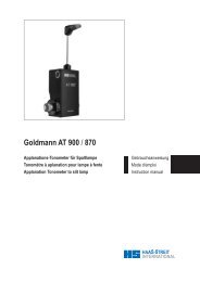
Introduction<br />
We would like to thank you for your decision to purchase this<br />
HAAG-STREIT product.<br />
If the instructions in this manual are carefully followed we are<br />
confident that this product will give you reliable and troublefree<br />
usage.<br />
Only properly trained and authorized persons are to operate<br />
the Slit Lamp <strong>BQ</strong> 900 ® .<br />
We will be forced to disclaim any warranty and liability if the<br />
instrument is altered in any way or if routine maintenance is<br />
neglected or not carried out according to factory specifications.<br />
Only original HAAG-STREIT spare parts are to be used to<br />
ensure continued reliability of the instrument.<br />
Purpose of use<br />
The Slit Lamp <strong>BQ</strong> 900 ® is used, at room temperature, in the<br />
examination, diagnosis and documentation of the human eye.<br />
It is usually used by Ophthalmologists, Optometrists or Opticians<br />
in their consulting rooms, clinics, hospitals or teaching<br />
facilities.<br />
NOTICE<br />
All rights to technical alterations reserved<br />
1500.7001000.<strong>04050</strong><br />
© HAAG-STREIT AG, CH-3098 Koeniz, Switzerland<br />
page 1 / 33
Inhaltsverzeichnis<br />
Kurzanleitung<br />
1 Übersicht<br />
1.1 Kopfhalter<br />
1.2 Spaltlampe <strong>BQ</strong> 900 ®<br />
2 Sicherheit<br />
2.1 Sicherheitsvorschriften<br />
2.2 Transport, Lagerung und Montage<br />
2.3 Benutzungshinweise<br />
2.4 Gesetzliche Vorschriften<br />
2.5 Warnhinweise<br />
2.6 Piktogramme<br />
3 Gerätebeschreibung<br />
3.1 Beleuchtungseinrichtung<br />
3.2 Stereomikroskop<br />
3.3 Zubehör<br />
4 Gerätebedienung<br />
4.1 Beleuchtungseinrichtung<br />
4.2 Einstellung Okulare / Augenmuschel<br />
4.3 Möglichkeiten der Helligkeitsregulierung<br />
Anhang A Gerätemontage<br />
A.1 Montage von Mikroskop und Beleuchtung<br />
A.2 Montage von Kopfhalter und Gerätenetzteil<br />
A.3 Instrumentenbasis mit Gewichtsausgleich<br />
A.4 Zubehör im Strahlengang anschliessen<br />
Anhang B Gerätewartung<br />
B.1 Auswechseln der Glühlampe<br />
B.2 Elektrische Kontakte Glühlampe und<br />
Lampengehäuse prüfen<br />
B.3 Auswechseln des Beleuchtungsspiegels<br />
B.4 Reinigen der Optik<br />
B.5 Reinigen der Gleitplatte<br />
und der Zahnschienen<br />
B.6 Regulieren der Gängigkeit der<br />
Spalteinstellung<br />
B.7 Rollachse reinigen<br />
B.8 Staubhülle<br />
Anhang C Technische Daten<br />
Seite<br />
4<br />
6<br />
6<br />
6<br />
8<br />
8<br />
8<br />
8<br />
10<br />
11<br />
11<br />
12<br />
12<br />
12<br />
14<br />
18<br />
18<br />
20<br />
20<br />
22<br />
22<br />
22<br />
24<br />
24<br />
26<br />
26<br />
26<br />
26<br />
28<br />
28<br />
28<br />
28<br />
28<br />
30<br />
Table des matières<br />
Généralités<br />
1 Nomenclature<br />
1.1 Appui-tête<br />
1.2 Lampe à fente <strong>BQ</strong> 900 ®<br />
2 Sécurité<br />
2.1 Prescriptions de sécurité<br />
2.2 Transport, stockage et montage<br />
2.3 Notes d’utilisation<br />
2.4 Dispositions légales<br />
2.5 Avertissements<br />
2.6 Pictogrammes<br />
3 Description de l'appareil<br />
3.1 Dispositif d'éclairage<br />
3.2 Microscope stéréoscopique<br />
3.3 Accessoires<br />
4 Utilisation de l'appareil<br />
4.1 Dispositif d'éclairage<br />
4.2 Réglage des oculaires / bonnettes<br />
4.3 Possibilités de réglage de la luminosité<br />
Annexe A Montage de l'appareil<br />
A.1 Montage du microscope et de l'éclairage<br />
A.2 Montage de l'appui-tête et de l'alimentation secteur<br />
A.3 Base d'instrument avec équilibrage de poids<br />
A.4 Monter un accessoire dans la marche des rayons<br />
Annexe B Entretien de l'appareil<br />
B.1 Remplacement de l'ampoule<br />
B.2 Examiner les contacts électriques de l'ampoule<br />
et du boîtier de la lampe<br />
B.3 Remplacement du miroir<br />
B.4 Nettoyage de l'optique<br />
B.5 Nettoyage de la plaque de glissement<br />
et des rails dentés<br />
B.6 Réglage<br />
du pas de la fente<br />
B.7 Nettoyage de l'axe<br />
B.8 Housse en plastique<br />
Annexe C Caractéristiques techniques<br />
page 2 / 33 © HAAG-STREIT AG, CH-3098 Koeniz, Switzerland<br />
1500.7001000.<strong>04050</strong><br />
page<br />
4<br />
6<br />
6<br />
6<br />
8<br />
8<br />
8<br />
8<br />
10<br />
11<br />
11<br />
12<br />
12<br />
12<br />
14<br />
18<br />
18<br />
20<br />
20<br />
22<br />
22<br />
22<br />
24<br />
24<br />
26<br />
26<br />
26<br />
26<br />
28<br />
28<br />
28<br />
28<br />
28<br />
28<br />
30
Contents<br />
Summary operating instruction<br />
1 Overview<br />
1.1 Headrest<br />
1.2 Slit lamp <strong>BQ</strong> 900 ®<br />
2 Operating safety<br />
2.1 Safety regulations<br />
2.2 Transportation, storage and installation<br />
2.3 Notes on usage<br />
2.4 Statutory requirements<br />
2.5 Caution<br />
2.6 Pictograms<br />
3 Description of the equipment<br />
3.1 Illumination unit<br />
3.2 Stereo microscope<br />
3.3 Accessories<br />
4 Operating the equipment<br />
4.1 Illumination unit<br />
4.2 Adjusting the eyepieces / eyeguards<br />
4.3 Possibilities for regulating the brightness<br />
Appendix A Installation of the equipment<br />
A.1 Mounting the microscope and the illumination unit<br />
A.2 Mounting of headrest and power supply<br />
A.3 Instrument base with load compensation<br />
A.4 Attaching an accessory in the beam path<br />
Appendix B Equipment maintenance routines<br />
B.1 Replacement of the bulb<br />
B.2 Check electrical contacts of bulb and<br />
lamp housing<br />
B.3 Replacement of the mirror<br />
B.4 Cleaning of the optical parts<br />
B.5 Cleaning of the gliding plate<br />
and the rails<br />
B.6 Adjustment of friction<br />
of the slit width control<br />
B.7 Cleaning of the axle<br />
B.8 Plastic dust cover<br />
Appendix C Technical specifications<br />
1500.7001000.<strong>04050</strong><br />
page<br />
5<br />
6<br />
6<br />
6<br />
9<br />
9<br />
9<br />
9<br />
11<br />
11<br />
11<br />
13<br />
13<br />
13<br />
14<br />
19<br />
19<br />
21<br />
21<br />
23<br />
23<br />
23<br />
25<br />
25<br />
27<br />
27<br />
27<br />
29<br />
29<br />
29<br />
29<br />
29<br />
29<br />
31<br />
© HAAG-STREIT AG, CH-3098 Koeniz, Switzerland<br />
page 3 / 33
Kurzanleitung<br />
1. Mit der Drehschraube (7) die Kinnstütze (6) so einstellen,<br />
dass sich die Augen des Patienten auf der Höhe der seitlich<br />
am Kopfhalter angebrachten schwarzen Marke (4) befinden.<br />
2. Okulare entsprechend der Refraktion des Untersuchers<br />
durch Drehen an den gerändelten Ringen sowie den Augenabstand<br />
einstellen.<br />
3. Beleuchtung durch Drehen des Schalters am Gerätenetzteil<br />
einschalten.<br />
4. Spaltlampe durch Drehen des Lenkhebels (34) in der Höhe<br />
verstellen, bis sich das Lichtbündel auf Augenhöhe befindet.<br />
5. Mit dem leicht gegen den Untersucher geneigten starr<br />
geführten Lenkhebel (34) verschiebt man das ganze Instrument,<br />
bis der Spalt annähernd scharf auf der Hornhaut abgebildet<br />
erscheint. Die Überprüfung dieser groben Einstellung<br />
erfolgt von blossem Auge. Feineinstellungen erreicht man<br />
durch Kippen des am oberen Ende leicht geführten Lenkhebels<br />
unter Beobachtung durch das Stereomikroskop (25).<br />
6. Die Spaltbreite wird links oder rechts mit dem Drehknopf<br />
(18) eingestellt, ebenso der Winkel zwischen Stereomikroskop<br />
und Beleuchtung.<br />
7. Das Spaltbild kann durch Drehen der Beleuchtungseinrichtung<br />
am Griff (22) vertikal, horizontal oder beliebig schräg<br />
gestellt werden (Raster bei 45°, 90° und 135°; Anschläge bei<br />
0° und 180°).<br />
8. Nach Auslösen der Klinke (30) kann der Lichteinfall bis zu<br />
20° geneigt werden.<br />
9. Die Vergrösserung des Stereomikroskops wird durch den<br />
Drehgriff des Vergrösserungswechslers (12) geändert.<br />
10. Zur Beobachtung im regredienten Licht wird die Zentrierschraube<br />
(29) gelöst, um das Spaltbild aus der Gesichtsfeldmitte<br />
zu bewegen. Das Festziehen der Schraube zentriert das<br />
Spaltbild wieder.<br />
11. Zur Übersichtsbeobachtung wird das Graufilter durch den<br />
Hebel (9) vorgeschaltet und die Spaltblende voll geöffnet.<br />
12. Zur Untersuchung des Augenhintergrundes werden Vorsatz-<br />
oder Kontaktgläser verwendet.<br />
Généralités<br />
1. Ajuster l'appui menton (6) à l’aide de la vis (7) de manière<br />
à ce que les yeux du patient se trouvent au niveau de la<br />
marque noire (4).<br />
2. Régler les oculaires à sa vue ainsi que l'écart interpupillaire.<br />
3. Enclencher l’éclairage en tournant l’interrupteur du bloc<br />
d’alimentation.<br />
4. Ajuster la lampe à fente verticalement en tournant le<br />
palonnier (34) jusqu’à ce que le faisceau de lumière se trouve<br />
au niveau des yeux.<br />
5. Déplacer l'ensemble de l’instrument à l’aide du palonnier<br />
(34) jusqu’à ce que la fente apparaisse nette sur la cornée.<br />
Vous pouvez vérifier ce réglage préalable à l’œil nu. Affinez le<br />
réglage si nécessaire et observez les effets au microscope<br />
stéréoscopique (25).<br />
6. Vous pouvez régler la largeur de la fente à gauche ou à<br />
droite avec le bouton de réglage (18), ainsi que l’angle entre<br />
le microscope stéréoscopique et la lampe.<br />
7. Vous pouvez mettre l’image de la fente en position verticale,<br />
horizontale ou oblique en faisant pivoter le dispositif d’éclairage<br />
avec la poignée (22) (cran à 45°, 90° et 135°; butées à 0° et<br />
180°).<br />
8. Après avoir déclenché le loquet (30), la direction de la<br />
lumière peut être inclinée jusqu’à 20°.<br />
9. Pour modifier le grossissement, il faut tourner la poignée du<br />
changeur de grossissement (12).<br />
10. Pour observer en lumière réfléchie, vous devez desserrer<br />
la vis de centrage (29) afin de décentrer la fente. En serrant<br />
la vis, l’image de la fente est centrée à nouveau.<br />
11. Pour faire des observations d’ensemble, activer le filtre<br />
gris avec le levier (9) et ouvrir le diaphragme complètement.<br />
12. Pour examiner le fond de l’œil, vous devez employer des<br />
verres intercalaires ou des verres de contact.<br />
page 4 / 33 © HAAG-STREIT AG, CH-3098 Koeniz, Switzerland<br />
1500.7001000.<strong>04050</strong>
Summary operating instructions<br />
1. Move the chin rest (6) up or down with the adjustment screw<br />
(7) until the eyes of the patient are level with the black mark on<br />
the headrest column (4).<br />
2. Focus the eyepieces to suit your refraction by turning the<br />
knurled rings and then set to your interpupillary distance.<br />
3. Switch on the illumination unit by turning the power supply<br />
switch.<br />
4. Rotate the control lever (34) until the light beam is at eye<br />
level.<br />
5. Holding the control lever (34), inclined towards yourself,<br />
move the instrument base until the slit appears to be approximately<br />
in focus on the cornea. This coarse setting is achieved<br />
with the naked eye. Fine adjustments are obtained by rotating<br />
and tilting the lever while observing the image through the<br />
microscope (25).<br />
6. The slit width is adjusted to the left or right by means of the<br />
knob (18), which also adjusts the angle between the microscope<br />
and the illumination unit.<br />
7. The slit image is made vertical, horizontal, or given any<br />
desired angle by means of control knob (22) (notches at 45°,<br />
90° and 135°; stops at 0° and 180°).<br />
8. The slit image can also be inclined to 20° by releasing the<br />
latch (30).<br />
9. Microscope magnification is changed by rotating the magnification<br />
changer (12).<br />
10. Loosening the centering screw (29) will allow the slit image<br />
to be moved off center for scleral illumination. Tightening the<br />
screw will recenter the slit image in the visual field of the<br />
microscope.<br />
11. For general observations over a wide field the grey filter is<br />
placed in position by means of lever (9), and the slit is opened<br />
wide.<br />
12. For examination of the posterior of the eye, preset lenses<br />
or diagnostic contact lenses have to be used.<br />
1500.7001000.<strong>04050</strong><br />
4<br />
6<br />
7<br />
© HAAG-STREIT AG, CH-3098 Koeniz, Switzerland<br />
9<br />
22<br />
12<br />
25<br />
29<br />
30<br />
18<br />
34<br />
page 5 / 33
1 Übersicht<br />
1.1 Kopfhalter<br />
1 Lampenkabel<br />
2 Kopfhalter<br />
3 Stirnband<br />
4 Höhenmarke am Kopfhalter<br />
(Patientenauge)<br />
5 Verstellbare Fixierlampe<br />
6 Kinnstütze<br />
7 Höhenverstellung der Kinnstütze<br />
1.2 Spaltlampe <strong>BQ</strong> 900 ®<br />
8 Lampendeckel<br />
9 Hebel für Grau- und Rotfreifilter<br />
10 Skala für Winkellage der<br />
Spaltabbildung<br />
11 Beleuchtungsspiegel<br />
12 Drehgriff des Vergrösserungswechslers<br />
13 Befestigungsschraube für<br />
Stereomikroskop<br />
14 Schutzdeckel<br />
15 Winkelskala zwischen Beleuchtung<br />
und Stereomikroskop<br />
16 Rändelknopf zum Blockieren der<br />
Beleuchtung auf Mikroskoparm<br />
17 Rändelknopf zum Blockieren<br />
des Mikroskoparms<br />
18 Rändelknopf zum Einstellen der<br />
Spaltbreite<br />
19 Schraube für Gewichtsausgleich<br />
20 Markenzeichen <strong>BQ</strong> 900 ®<br />
21 Skala für Spaltlänge / Blenden<br />
22 Rändelknopf zum Einstellen Spaltlänge,<br />
Blaufilter, Fixationsstern,<br />
Griff zum Drehen des Spaltes<br />
23 Abdeckschraube für<br />
Zubehörzapfen<br />
24 Bajonettverschluss Zubehör<br />
25 Stereomikroskop mit Okularen<br />
26 Atemschutzschild<br />
27 Befestigungsschraube für<br />
Atemschutzschild<br />
28 Gewinde zur Befestigung des Tonometers<br />
AT 900 <strong>BQ</strong> (rechte Seite)<br />
29 Zentrierschraube<br />
30 Klinke für Neigungswinkel 5° - 20°<br />
31 Schraube zum Blockieren<br />
horizontaler Bewegungen<br />
32 Rollachse<br />
33 Schienendeckel<br />
34 Lenkhebel<br />
35 Gleitplatte<br />
1 Nomenclature<br />
1.1 Appui-tête<br />
1 Câble d'alimentation<br />
2 Appui-tête<br />
3 Bandeau appui-front<br />
4 Indicateur de la hauteur<br />
(des yeux du patient)<br />
5 Point de fixation réglable<br />
6 Appui-menton<br />
7 Réglage de la hauteur<br />
de l'appui-menton<br />
1.2 Lampe à fente <strong>BQ</strong> 900 ®<br />
8 Couvercle du boîtier de la lampe<br />
9 Levier pour les filtres gris et vert<br />
10 Echelle pour la position angulaire<br />
11 Miroir de la lampe<br />
12 Poignée du changeur de<br />
grossissement<br />
13 Vis de fixation pour microscope<br />
stéréoscopique<br />
14 Couvercle de protection<br />
15 Graduation angulaire entre la<br />
lampe et le microscope<br />
16 Blocage de l'illumination<br />
17 Blocage du bras du microscope<br />
18 Bouton rotatif pour régler<br />
la largeur de la fente<br />
19 Vis pour réglage de l'égalisation<br />
de charge<br />
20 Marque déposée <strong>BQ</strong> 900 ®<br />
21 Echelle pour la longueur<br />
de la fente / diaphragmes<br />
22 Bouton moleté pour régler la<br />
longueur de la fente, le filtre bleu,<br />
étoile de fixation, poignée pour<br />
faire tourner la fente<br />
23 Cache-vis protecteur pour la<br />
goupille des accessoires<br />
24 Fermeture baïonette accessoires<br />
25 Microscope stéréoscopique avec<br />
oculaires<br />
26 Plaque de protection hygiénique<br />
27 Vis de fixation pour plaque de prot.<br />
28 Filetage pour fixation du tonomètre<br />
AT 900 <strong>BQ</strong> (côté droite)<br />
29 Vis de centrage<br />
30 Loquet de l'angle d'inclination<br />
5°-20°<br />
31 Vis pour bloquer les mouvements<br />
horizontaux<br />
32 Axe<br />
33 Cache-rail<br />
34 Palonnier<br />
35 Plaque de glissement<br />
1 Overview<br />
1.1 Headrest<br />
1 Lamp cable<br />
2 Headrest<br />
3 Forehead band<br />
4 Headrest height marker<br />
(patient's eye)<br />
5 Adjustable focusing target<br />
6 Chin rest<br />
7 Chin rest height adjustment<br />
1.2 Slit Lamp <strong>BQ</strong> 900 ®<br />
8 Lamp cover<br />
9 Lever for grey - and redfree filter<br />
10 Scale for angled position<br />
of the slit image<br />
11 Interchangeable illumination mirror<br />
12 Magnification changer<br />
13 Mounting screw for the<br />
stereo microscope<br />
14 Protective cover<br />
15 Illumination unit / microscope<br />
angle scale<br />
16 Illumination arm locking screw<br />
17 Microscope arm locking screw<br />
18 Slit width controls<br />
19 Screw fer weight compensation<br />
20 Registered trade mark <strong>BQ</strong> 900 ®<br />
21 Slit diaphragm scale<br />
22 Slit length, slit rotation,<br />
blue filter and fixation star control<br />
23 Cap screw for accessories pin<br />
24 Bayonet connector accessory<br />
25 Stereo microscope with<br />
eyepieces<br />
26 Breath shield<br />
27 Mounting screw for breath shield<br />
28 Mounting hole for tonometer<br />
AT 900 <strong>BQ</strong> (right side)<br />
29 Centering screw<br />
30 5° to 20° inclination angle latch<br />
31 Joy stick base locking screw<br />
32 Axle<br />
33 Rail covers<br />
34 Control lever<br />
35 Gliding plate<br />
page 6 / 33 © HAAG-STREIT AG, CH-3098 Koeniz, Switzerland<br />
1500.7001000.<strong>04050</strong>
Kopfhalter / Appui-tête / Headrest Spaltlampe / Lampe à fente / Slit Lamp<br />
1<br />
2<br />
3<br />
4<br />
5<br />
6<br />
7<br />
1500.7001000.<strong>04050</strong><br />
8<br />
9<br />
10<br />
11<br />
12<br />
13<br />
14<br />
15<br />
16<br />
17<br />
18<br />
19<br />
© HAAG-STREIT AG, CH-3098 Koeniz, Switzerland<br />
20<br />
21<br />
22<br />
23<br />
24<br />
25<br />
26<br />
27<br />
28<br />
29<br />
30<br />
31<br />
32<br />
33<br />
34<br />
35<br />
page 7 / 33
2 Sicherheit<br />
2.1 Sicherheitsvorschriften<br />
Zur Gewährleistung der Sicherheit des Patienten sind<br />
folgende Hinweise zu beachten:<br />
• Auf der Oberseite des Lampengehäuses können erhöhte<br />
Temperaturen auftreten.<br />
• Es darf nur ein typengeprüftes 3-poliges Netzkabel<br />
verwendet werden.<br />
• Für <strong>USA</strong> und Kanada<br />
Es darf nur ein typengeprüftes 3-poliges Netzkabel verwendet<br />
werden. Netzkabelset, nach UL-Liste, Typ SJE, SJT oder<br />
SJO, 3-polig, nicht kleiner als 18 AWG.<br />
2.2 Transport, Lagerung und Montage<br />
• Die Spaltlampe darf folgenden Umweltbedingungen für<br />
Transport und Lagerung (offen oder in der Verpackung) für<br />
max. 15 Wochen ausgesetzt werden:<br />
• Umgebungstemperatur: von -10 °C bis +60 °C<br />
• Luftdruck: von 500 hPa bis 1060 hPa<br />
• Relative Feuchte: von 10 % bis 90 %, wobei sich das<br />
Gerät vor dem Auspacken in der Verpackung für einige<br />
Stunden an die neue Umgebungstemperatur anpassen muss<br />
(Vermeidung von Kondensation).<br />
• Die Stationierung des Gerätes in feuchten Räumen ist<br />
verboten. In der Nähe des Gerätes sind Spritz-, Tropf- oder<br />
Schwallwasser zu vermeiden.<br />
• Die Spaltlampe und der Kopfhalter müssen immer auf<br />
einer elektrisch isolierten Tischplatte montiert werden, wie<br />
z.B. eine Platte aus Holz, Kunststoff usw. Die Platte muss<br />
feuerfest sein.<br />
2.3 Benutzungshinweise<br />
• Nur qualifiziertes und geschultes Personal darf das<br />
Gerät bedienen.<br />
• Die Ausbildung des Bedienungspersonals ist Aufgabe<br />
des Gerätebetreibers.<br />
• Die Benutzung des Gerätes in explosions-gefährdeten<br />
Bereichen ist verboten. Der Betrieb in Gegenwart von flüchtigen<br />
Lösungsmitteln wie Alkohol, Benzin oder ähnlichen sowie<br />
von brennbaren Narkosemitteln ist untersagt.<br />
• Der Benutzer darf die Spaltlampe <strong>BQ</strong> 900 ® nur zum<br />
Lampenwechsel öffnen. Jeder weitere Eingriff am Gerät kann<br />
die Sicherheit für den Arzt und den Patienten gefährden.<br />
• Vor dem Lampenwechsel: die Spaltlampe <strong>BQ</strong> 900 ® am<br />
Netzschalter ausschalten, den Netzstecker ausziehen und<br />
die Lampe einige Minuten abkühlen lassen.<br />
• Das Gerät darf nur mit dem aufgeführten Zubehör gemäss<br />
der Gebrauchsanweisung oder der separaten Gebrauchsanweisung<br />
des Zubehörs betrieben werden.<br />
• Die Schienendeckel (33) müssen montiert werden, um<br />
ein Umkippen der Spaltlampe zu verhindern.<br />
• Um mögliche Augenschäden zu vermeiden, ist mit den<br />
Okularen niemals in die Sonne zu blicken.<br />
2 Sécurité<br />
2.1 Prescriptions de sécurité<br />
Afin de garantir la sécurité du patient, il est impératif de<br />
respecter les règles suivantes:<br />
• Des températures très élevées peuvent subvenir sur la<br />
partie supérieure du boîtier de la lampe.<br />
• N'utiliser qu'un câble d'alimentation secteur tripolaire<br />
homologué.<br />
• Pour <strong>USA</strong> et Canada<br />
Câble d'alimentation: N'utiliser qu'un câble d'alimentation<br />
tripolaire homologué. Câble d'alimentation électrique, selon<br />
UL, type SJE, SJT ou SJO, tripolaire plus grand que 18 AWG.<br />
2.2 Transport, stockage et montage<br />
• L'appareil peut être exposé aux conditions atmosphériques<br />
suivantes pendant son transport et son stockage<br />
(ouvert ou bien emballé) pendant 15 semaines maximum:<br />
• Température ambiante de -10 °C à +60 °C<br />
• Pression atmosphérique comprise entre 500 hPa et<br />
1060 hPa<br />
• Humidité relative comprise entre 10 % et 90 %; on doit<br />
toutefois veiller à laisser l’appareil dans son emballage pendant<br />
quelques heures pour lui permettre de s’adapter à la<br />
nouvelle température ambiante (ceci afin d’éviter toute condensation).<br />
• Il est interdit de stocker l'appareil dans des locaux<br />
humides. Vous devez éviter toute source d'humidité (éclaboussure<br />
d'eau, jet d'eau) à proximité de l'appareil.<br />
• Monter toujours la lampe à fente et l'appui-tête sur un<br />
plateau de table électriquement isolé, comme par exemple<br />
bois, plastique, etc. Le plateau de la table doit être résistant au<br />
feu.<br />
2.3 Notes d’utilisation<br />
• Seul un personnel qualifié et formé a le droit d’utiliser cet<br />
appareil.<br />
• La formation des opérateurs incombe au propriétaire de<br />
l’appareil.<br />
• Il est interdit d'utiliser l'appareil dans des zones où il y a<br />
danger d'explosion. Il est strictement interdit d'utiliser l'appareil<br />
en présence de substances volatiles (alcool, essence, etc., ou<br />
produits narcotiques inflammables).<br />
• L'utilisateur a uniquement le droit d'ouvrir la lampe à fente<br />
<strong>BQ</strong> 900 ® pour remplacer l'ampoule. Toute autre manipulation<br />
de l'appareil peut entraver la sécurité du médecin ou du patient.<br />
• Avant de remplacer l'ampoule: vous devez couper le<br />
contact de l'interrupteur principal, débrancher le câble de<br />
réseau et laisser refroidir l'ampoule pendant quelques minutes.<br />
• L'appareil doit être utilisé uniquement avec les pièces<br />
accessoires mentionnées dans cette notice d'emploi ou dans<br />
la notice d'emploi des pièces accessoires en annexe.<br />
• Les cache-rails (33) doivent être montés pour éviter un<br />
renversement de la lampe à fente.<br />
• Pour éviter d'endommager les yeux, ne regarder jamais<br />
dans l'oculaire en plein soleil.<br />
page 8 / 33 © HAAG-STREIT AG, CH-3098 Koeniz, Switzerland<br />
1500.7001000.<strong>04050</strong>
2 Operating safety<br />
2.1 Safety regulations<br />
The following instructions should be observed to ensure<br />
the safety of patients:<br />
• The temperature of the upper surface of the lamp housing<br />
might increase during operation.<br />
• Only a hospital grade 3-conductor electrical power supply<br />
cable must be used.<br />
• For <strong>USA</strong> and Canada<br />
Only a hospital grade 3-conductor electrical power supply<br />
cable must be used.<br />
Detachable Power Supply Cord Set, UL Listed, type SJE, SJT<br />
or SJO, 3-conductor, not smaller than 18 AWG.<br />
2.2 Transportation, storage and installation<br />
• As long as the equipment remains in its original packaging,<br />
it may be exposed to the following environmental/<br />
ambient conditions for transportation and storage purposes<br />
(opened or in the packaging) for a maximum of 15 weeks:<br />
•a range of ambient temperatures from -10 °C to +60 °C<br />
•a range of air pressures from 500 hPa to 1060 hPa<br />
•a relative humidity range from 10 % to 90 %, whereby<br />
the equipment should be allowed to adjust to the ambient<br />
temperature of the new location for several hours in the<br />
packaging (to avoid the forming of condensation).<br />
• Do not operate the equipment in humid locations. Ensure<br />
that no splashing, dripping or excessive surges of water<br />
occur near the equipment.<br />
• Always mount the slit lamp and the headrest on an<br />
electric insulated table top, like wood, plastic, etc. The table<br />
top must be fire resistant.<br />
2.3 Notes on usage<br />
• Only qualified and trained personnel should be permitted<br />
to operate the equipment.<br />
• The training of the operating personnel is the responsibility<br />
of the owner of the equipment.<br />
• It is hazardous to operate the equipment in locations<br />
where combustible gases or vapors could be present. The use<br />
of the equipment in the presence of volatile solvents such as<br />
alcohol, benzol or similar chemical products, as well as<br />
flammable anaesthetic agents is also hazardous.<br />
• The user should only open the slit lamp <strong>BQ</strong> 900 ® to<br />
change the light bulb. Any other intervention on the equipment<br />
can be hazardous to the safety of the examiner and the patient.<br />
• Before changing the light bulb: switch off the slit lamp<br />
<strong>BQ</strong> 900 ® , unplug and allow the light bulb to cool down for<br />
several minutes.<br />
• The equipment may only be operated with the listed<br />
accessories in accordance with the instruction manual or with<br />
the separate specific instruction manual for the accessories.<br />
• The rail covers (33) must be mounted to prevent from a<br />
tip over of the slit lamp.<br />
• In order to avoid possible eye damage, the sun should<br />
never be viewed through the ocular.<br />
1500.7001000.<strong>04050</strong><br />
© HAAG-STREIT AG, CH-3098 Koeniz, Switzerland<br />
page 9 / 33
• Eine lange und intensive Beleuchtung kann die Retina<br />
schädigen. Die Helligkeitseinstellung sollte daher den Wert<br />
nicht überschreiten, welcher für eine klare Darstellung der<br />
Zielstrukturen benötigt wird. Eine Untersuchung mit diesem<br />
Gerät darf nicht unnötig ausgedehnt werden.<br />
• Die retinale Dosis für eine fotochemische Gefährdung setzt<br />
sich aus der Strahldichte und der Bestrahlungszeit zusammen:<br />
Wird die Strahldichte um die Hälfte reduziert, verdoppelt sich die<br />
Zeit, bis der Grenzwert der Bestrahlungszeit erreicht wird.<br />
• Bisher wurde keine akute optische Strahlungsgefährdung<br />
bei Spaltlampen nachgewiesen. Wir empfehlen aber<br />
trotzdem, die Intensität des Lichtes, welches auf die Retina<br />
des Patienten fällt, auf das mögliche Minimum für die jeweilige<br />
Diagnose zu beschränken. Kinder, Aphake und Personen mit<br />
erkrankten Augen sind am meisten gefährdet.<br />
Erhöhtes Risiko kann auch dann bestehen, wenn die Retina<br />
innerhalb von 24 Stunden dem gleichen oder einem anderen<br />
Instrument mit sichtbarer Lichtquelle ausgesetzt wird. Dies<br />
gilt besonders, wenn die Retina vorher mit einem Blitzlicht<br />
fotografiert wird.<br />
• Alle Stecker und Kabel müssen sich in einwandfreiem<br />
Zustand befinden.<br />
• Die Steckdose, in welche der Netzstecker eingeführt<br />
wird, muss über einen einwandfreien Schutzleiteranschluss<br />
verfügen.<br />
• Die zur Gerätesicherheit dienenden Verbindungsteile<br />
haben einen einwandfreien Sitz. Die Schraubverbindungen,<br />
beispielsweise für das Zubehör, sind fest angezogen.<br />
• Den Netzschalter nach jedem Betrieb des Gerätes durch<br />
Drehen auf die Nullstellung (0) ausschalten.<br />
• Zur Reinigung des Spaltlampengehäuses ist ein leicht<br />
angefeuchtetes Tuch zu benutzen, damit keine Flüssigkeit in<br />
das Gerät eindringt (keine ätzenden Mittel verwenden).<br />
• Entsprechend den Hinweisen in dieser Gebrauchsanweisung<br />
sind nur die Aussenflächen der Optikteile zu säubern.<br />
• Instandsetzungen und Änderungen an diesem Gerät<br />
dürfen nur von unseren Servicetechnikern oder von autorisierten<br />
Personen durchgeführt werden. Der Gerätehersteller<br />
haftet nicht für Schäden, welche durch unautorisierte Eingriffe<br />
in das Gerät entstehen. Ausserdem erlöschen dadurch sämtliche<br />
Garantieansprüche.<br />
2.4 Gesetzliche Vorschriften<br />
• Die Spaltlampe <strong>BQ</strong> 900 ® wurde unter Berücksichtigung<br />
der Normen EN 60 601-1 und ISO 10939 konstruiert. Unter der<br />
Beachtung schweizerischer und internationaler Auflagen erfolgen<br />
Fertigung, Prüfung, Aufstellung, Wartung und Reparatur.<br />
• Durch die CE-Kennzeichnung wird die Übereinstimmung<br />
der Spaltlampe <strong>BQ</strong> 900 ® mit den Richtlinien 93/42/EWG und<br />
89/336/EWG und dem Konformitätsmodul A bestätigt.<br />
• Die gesetzlichen Unfallverhütungsvorschriften sind zu<br />
beachten.<br />
• Klassierung<br />
Norm IEC 601-1 Spaltlampe <strong>BQ</strong> 900 ® nach<br />
Schutzklasse I<br />
Anwendungsteil Typ B<br />
Betriebsart: Dauerbetrieb<br />
CE-Richtlinie 93/42 EWG Klasse I<br />
FDA Klasse II<br />
• Un éclairage long et intensif peut endommager la rétine.<br />
Le réglage de la luminosité ne devrait pas dépasser la valeur<br />
qui est nécessaire à une bonne représentation des structures<br />
ciblées. Un examen avec cet appareil ne doit pas être inutilement<br />
prolongé.<br />
• La dose photochimique à risque pour la rétine se compose<br />
de l'intensité de rayonnement et du temps de l'examen:<br />
si l'intensité de rayonnement est réduite de moitié, le temps<br />
est multiplié par deux jusqu'à obtention de la valeur limite du<br />
temps d'exposition.<br />
• Jusqu' à présent, il n'a pu être constaté aucun risque<br />
d'irradiation imminent avec les lampes à fente. Nous recommandons<br />
cependant de limiter autant que possible l'intensité<br />
lumineuse dirigée sur la rétine du patient pour effectuer les<br />
différents diagnostics. Les enfants, les personnes aphaques<br />
ou aux yeux fragiles sont les plus exposés.<br />
Un risque accru peut également exister si la rétine est exposée<br />
dans une période de 24 heures au même instrument ou<br />
à un autre instrument avec une source lumineuse visible.<br />
C'est en particulier le cas si la rétine a été photographiée<br />
auparavant avec flash.<br />
• Toutes les fiches et tous les câbles doivent être en<br />
parfait état.<br />
• La prise de courant est munie d'un conducteur de<br />
protection en parfait état.<br />
• Les pièces de liaison servant à la sécurité de l'appareil<br />
ont un siège en parfait état. Par exemple, les raccords pour les<br />
accessoires sont serrés à bloc.<br />
• Veiller à remettre l'interrupteur du secteur après chaque<br />
utilisation de l'appareil, position zéro (0).<br />
• Pour le nettoyage du boîtier de la lampe à fente, utiliser<br />
un linge légèrement humide afin que du liquide ne pénètre pas<br />
dans l'appareil (ne pas utiliser de produits abrasifs).<br />
• Vous devez nettoyer les surfaces extérieures des pièces<br />
de l'optique selon les indications de cette notice d'emploi.<br />
• Seuls nos techniciens ou des personnes autorisées ont<br />
le droit de réparer ou de modifier l'appareil. Le constructeur<br />
décline toute responsabilité pour des dommages causés par<br />
des interventions non autorisées dans l'appareil. Par ailleurs,<br />
tous droits de garantie tombent.<br />
2.4 Dispositions légales<br />
• La lampe à fente <strong>BQ</strong> 900 ® a été conçue conformément<br />
aux normes EN 60 601-1 et ISO 10939. La fabrication, le test,<br />
le montage, l'entretien et la réparation doivent être effectués<br />
en respectant les dispositions légales suisses et internationales.<br />
• L'insigne CE indique que la lampe à fente <strong>BQ</strong> 900 ® est<br />
conforme aux prescriptions 93/42/CEE et 89/336/CEE et au<br />
module de conformité A.<br />
• Les dispositions légales de prévention des accidents<br />
doivent être observées.<br />
• Classification<br />
Norme IEC 601-1 Lampe à fente <strong>BQ</strong> 900 ®<br />
classe de protection I<br />
Partie d'application type B<br />
Mode d'exploitation: a longue durée<br />
Directive CE 93/42 CEE Classe I<br />
FDA Classe II<br />
page 10 / 33 © HAAG-STREIT AG, CH-3098 Koeniz, Switzerland<br />
1500.7001000.<strong>04050</strong>
• Long and intensive illumination could damage the retina.<br />
The brightness of illumination should be kept at a minimum,<br />
to view the structure of the target clearly. To avoid potential<br />
eye damage, the examination should not last longer than<br />
necessary.<br />
• The retinal dose for potential photo chemical damage<br />
depends on ray density and examination time. When the ray<br />
density is cut in half, the examination time doubles until the<br />
border value is reached.<br />
• Until today, there is no proof established that slit lamp<br />
examination can endanger the eye. Nevertheless, we recommend<br />
to use the minimum amount of light possible for retinal<br />
examination.<br />
Children, Aphakics and people with eye problems are especially<br />
endangered. If the retina is exposed to the same or<br />
another light source in 24 hours, there is also a higher risk.<br />
This is especially true when a retinal picture is taken with flash.<br />
• All electrical plugs and leads are to be maintained in<br />
perfect working condition.<br />
• The electrical supply socket to which the electrical plug<br />
of the equipment can be connected must have a perfectly<br />
functioning ground connection.<br />
• The connecting pieces of the equipment that serve to<br />
ensure safe operation are to have a proper fit. The screw<br />
connections for all accessories are to be firmly tightened.<br />
• The electrical supply should be disconnected at the<br />
power switch after the completion of operations.<br />
• The Slit Lamp housing should only be cleaned with a<br />
water dampened cloth - no corrosive agents are to be employed.<br />
• Only the exterior surfaces of the equipment are to be<br />
cleaned in accordance with the notes in the instruction manual.<br />
• Repairs and alterations on this equipment should only be<br />
carried out by our factory trained service technicians or by<br />
other authorized persons. The manufacturer will disclaim all<br />
liability for loss or damage resulting from any unauthorized<br />
repair attempts and the warranty will be rendered null and<br />
void.<br />
2.4 Statutory requirements<br />
• The Slit Lamp <strong>BQ</strong> 900 ® has been designed and constructed<br />
to conform with EN 60 601-1 and ISO 10939 standards.<br />
Manufacturing procedures, testing, assembling, maintenance<br />
and repair are conducted under the observance of Swiss and<br />
International regulations.<br />
• The "CE" marking confirms compliance of the Slit Lamp<br />
<strong>BQ</strong> 900 ® with directives 93/42/EEC and 89/336/EEC and the<br />
conformity module A.<br />
• All statutory accident prevention regulations are to be<br />
observed.<br />
• Classification<br />
IEC Standard 601-1 Slit Lamp <strong>BQ</strong> 900 ® equipment<br />
safety class I<br />
Application part Type B<br />
Operation mode - continuous<br />
operation<br />
CE-Regulation 93/42 EEC Class I<br />
FDA Class II<br />
1500.7001000.<strong>04050</strong><br />
2.5 Warnhinweise / Avertissements / Caution<br />
• Die hervorgehobenen Sicherheitshinweise in der Gebrauchsanweisung<br />
sind mit besonderer Aufmerksamkeit zu<br />
beachten.<br />
• Il est indispensable d’observer avec une attention particulière<br />
les règles de sécurité énumérées plus haut dans le<br />
présent mode d’emploi.<br />
• The safety aspects and information emphasized in the<br />
instruction manual are to be observed with special care.<br />
2.6 Piktogramme / Pictogrammes / Pictograms<br />
© HAAG-STREIT AG, CH-3098 Koeniz, Switzerland<br />
"Vor dem Öffnen des Gerätes den Netzstekker<br />
ziehen!"<br />
"Avant d'ouvrir l'appareil, retirez la prise électrique!"<br />
"Always disconnect the electrical supply before<br />
opening the equipment!"<br />
"Warnung vor heissen Oberflächen!"<br />
"Danger de surfaces chaudes!"<br />
"Warning for hot surfaces!"<br />
Bei Verwendung des Instrumententisches HSM-901 Typ M<br />
unbedingt diesen Sicherheitshinweis beachten<br />
Si vous utilisez la table d' instruments HSM-901 type M, vous<br />
devez faire attention aux indications de sécurité suivantes<br />
It is mandatory to observe the following safety precautions<br />
when operating the Instrument Table HSM-901, type M<br />
Patents: US Pat. 3.685.779<br />
and other countries<br />
Höhenverstellung nur mit<br />
aufgesetztem Gerät betätigen<br />
Do not use height adjustment<br />
without instrument in place<br />
Ne pas utiliser le réglage en hauteur<br />
quand l'instrument n'est pas en place<br />
HAAG-STREIT BERN<br />
SWISS MADE<br />
ACHTUNG<br />
Warnschilder unbedingt beachten!<br />
ATTENTION<br />
Faites attention aux pancartes d’avertissement!<br />
CAUTION<br />
Strictly observe all warning notices!<br />
page 11 / 33
3 Gerätebeschreibung<br />
3.1 Beleuchtungseinrichtung<br />
Glühlampe<br />
Die Wolfram-Glühlampe wird im Werk zentriert, um eine<br />
optimale Ausleuchtung zu gewährleisten. Die 'H-S' Markierung<br />
am Zentriersockel bezeichnet das HAAG-STREIT Originalteil.<br />
Das ausgestrahlte Licht der vorzentrierten Glühlampe passiert<br />
Kondensor, Spaltblende und Objektivlinse und wird über<br />
den schräg stehenden Spiegel in das Auge des Patienten<br />
gelenkt.<br />
Im Strahlengang der Beleuchtung befinden sich<br />
Filter (9)<br />
36 Offen<br />
38 Graufilter (10 %)<br />
39 Rotfreifilter<br />
40 Reserveöffnung für Filter nach Wahl<br />
Die europäische Gesetzgebung schreibt vor, dass der<br />
Wärmeschutzfilter fest eingebaut ist<br />
Blenden (21) Bedienung (22)<br />
41 Fixationsstern*<br />
42 Rundblenden von 8, 5, 3, 2, 1 und 0.2 mm ø<br />
43 Anzeige Keilblende für kontinuierliche Spaltlängenverstellung<br />
in mm<br />
44 Blaufilter<br />
* Der Fixationsstern dient vor allem zur Fixationsuntersuchung<br />
bei schielenden Kindern mit Amblyopie.<br />
3.2 Stereomikroskop<br />
45 Frontobjektiv<br />
f105 mm Winkel der optischen Achsen 13°<br />
12 Drehknopf mit Anzeige der eingestellten Vergrösserung<br />
46 Vergrösserungswechsler 5-stufig<br />
(Galilei-System)<br />
24 Rändelring Bajonett-Anschluss<br />
25 Binokulartubus f132 mm mit konvergentem Einblick,<br />
Pupillenabstand einstellbar 52 - 78 mm<br />
47 Okular 12.5 x Sehfeld ø 16 mm, verschiebbare<br />
Augenmuschel (auch für Brillenträger),<br />
Dioptrien einstellbar von + 8 bis - 8 D<br />
Gesamtvergrösserung 6.3 x 10 x 16 x 25 x 40 x<br />
Objektfeld ø in mm 32.0 20.0 12.7 8.0 5.1<br />
3 Description de l'appareil<br />
3.1 Dispositif d'éclairage<br />
L'ampoule<br />
L'ampoule de tungstène est centrée en usine pour assurer un<br />
éclairage optimal. Le signe 'H-S' sur le socle de centrage<br />
indique qu'il s'agit d'une pièce d'origine HAAG-STREIT.<br />
La lumière émise par l'ampoule centrée traverse le condensateur,<br />
le diaphragme et la lentille de l'objectif. Ensuite elle est<br />
déviée par un miroir oblique dans l'oeil du patient.<br />
Dans le faisceau de l'éclairage sont interposés<br />
Filtres (9)<br />
36 Ouvert<br />
38 Filtre gris (10 %)<br />
39 Filtre vert<br />
40 Ouverture de réserve pour filtre au choix<br />
La loi européenne exige que le filtre anti-calorique<br />
soit monté en permanence<br />
Diaphragmes (21) utilisation (22)<br />
41 Etoile de fixation*<br />
42 Diaphragme circulaire de 8, 5, 3, 2, 1 et de 0.2 mm ø<br />
43 Indication du diaphragme progressif pour le réglage<br />
continu de la longueur de la fente en mm<br />
44 Filtre bleu<br />
* L'étoile de fixation sert en premier lieu à examiner la fixation<br />
des enfants strabiques avec amblyopie.<br />
3.2 Microscope stéréoscopique<br />
45 Objectif frontal<br />
f105 mm angle de l'axe optique 13°<br />
12 Bouton avec indication de l'agrandissement sélectionné<br />
46 Changeur de grossissement à 5 niveaux<br />
(système Galilei)<br />
24 Bague moletée fermeture à baïonnette<br />
25 Tube binoculaire f132 avec vue d'entrée convergente,<br />
écart des pupilles réglable 52-78 mm<br />
47 Oculaire 12,5 x champ visuel ø 16 mm, bonnettes<br />
amovibles (aussi pour porteur de lunettes),<br />
dioptrie réglable de + 8 à - 8 D<br />
Grossissement 6.3 x 10 x 16 x 25 x 40 x<br />
Champ visuel ø en mm 32.0 20.0 12.7 8.0 5.1<br />
page 12 / 33 © HAAG-STREIT AG, CH-3098 Koeniz, Switzerland<br />
1500.7001000.<strong>04050</strong>
3 Description of equipment<br />
3.1 Illumination unit<br />
Lamp bulb<br />
The tungsten lamp bulb is centered ex-works to obtain an<br />
optimal illumination. The 'H-S' marking on the centering basecap<br />
indicates a genuine HAAG-STREIT spare part.<br />
The light beam from the pre-centered bulb passes through the<br />
condenser, the slit diaphragm and the illumination lens, before<br />
it is directed to the patient's eye by the oblique mirror.<br />
The following can be mounted in the path of the light beam of<br />
the illumination unit<br />
Filters (9)<br />
36 Open aperture<br />
38 Grey filter (10 %)<br />
39 Redfree filter<br />
40 Empty space for accommodating an additional filter<br />
Due to European law a heat absorption filter<br />
is permanently mounted<br />
Apertures (21) operating (22)<br />
41 Fixation star*<br />
42 Apertures producing areas of 8, 5, 3, 2, 1 and 0.2 mm ø<br />
43 Indication of wedge-shaped diaphragm for continuous<br />
slit length adjustment in mm<br />
44 Blue filter<br />
* The target with the fixation star is particularly suitable for<br />
examining the fixation in amblyopia.<br />
3.2 Stereo microscope<br />
45 Front lens<br />
f105 mm angle of optical axis 13°<br />
12 Turning knob with display of selected magnification<br />
46 Magnification changer 5 step<br />
(Galilean system)<br />
24 Knurled ring bayonet joint<br />
25 Binocular tube f132 for convergent viewing range of<br />
pupillary distance 52-78 mm<br />
47 Eyepiece 12.5 x<br />
Diameter of field 16 mm, sliding eyeguard (for spectacle<br />
wearers also), diopter adjustable from + 8 to - 8 D<br />
Total magnification 6.3 x 10 x 16 x 25 x 40 x<br />
Object image section ø in mm 32.0 20.0 12.7 8.0 5.1<br />
1500.7001000.<strong>04050</strong><br />
21<br />
9<br />
22<br />
© HAAG-STREIT AG, CH-3098 Koeniz, Switzerland<br />
36 38 39 40<br />
S 8 5 3 2 1<br />
0,2<br />
41 42 43 44<br />
45 12 46 24 25 47<br />
4<br />
'H-S'<br />
page 13 / 33
3.3 Zubehör zum Basismodell <strong>BQ</strong> 900 ®<br />
Accessoires pour le modèle de base <strong>BQ</strong> 900 ®<br />
Accessories for standard model <strong>BQ</strong> 900 ®<br />
rot / rouge / red<br />
gelb / jaune / yellow<br />
blau / bleu / blue<br />
Standard Okular <strong>BQ</strong> 900<br />
Oculaire standard <strong>BQ</strong> 900<br />
Standard eyepiece <strong>BQ</strong> 900<br />
12.5 x 1400303<br />
Identifikationsfarbe<br />
Couleur d'identification<br />
Identification colour<br />
Messokular<br />
Oculaire de mesure<br />
Measuring eyepiece<br />
12.5 x 1400302<br />
Okular mit Doppelfadenkreuz<br />
Oculaire avec double réticule croisée<br />
Eyepiece with double crosshair reticule<br />
12.5x 3000470<br />
Okular mit McIntyre Strichplatte<br />
Oculaire avec réticule de comparaison d'après McIntyre<br />
Eyepiece with McIntyre comparison grid<br />
12.5 x 1400304<br />
Wolfram-Glühlampe<br />
Ampoule de tungstène<br />
Tungsten lamp bulb<br />
3000353<br />
Halogenlampe<br />
Ampoule halogène<br />
Halogen bulb<br />
1300068<br />
Spiegel lang<br />
Miroir long<br />
Mirror long<br />
1001590<br />
Spiegel kurz<br />
Miroir court<br />
Mirror short<br />
1001591<br />
mit HAAG-STREIT Bestellnummern<br />
numéros de référence HAAG-STREIT<br />
with HAAG-STREIT part numbers<br />
Goldmann Applanations Tonometer<br />
Tonomètre à aplanation Goldmann<br />
Goldmann Applanation Tonometer<br />
AT 900 <strong>BQ</strong> 7200034<br />
Goldmann Applanations Tonometer<br />
(inklusive Führungsplatte)<br />
Tonomètre à aplanation Goldmann<br />
(inclusif plaque de guidage)<br />
Goldmann Applanation Tonometer<br />
(guide plate included)<br />
AT 900 M/Q 7200032<br />
Justierstab<br />
Tige d'ajustage<br />
Focusing rod<br />
1001051<br />
page 14 / 33 © HAAG-STREIT AG, CH-3098 Koeniz, Switzerland<br />
1500.7001000.<strong>04050</strong>
Kopfhalter mit Fixierlampe*<br />
Appui-tête avec lampe de fixation*<br />
Headrest with fixation lamp*<br />
1500.7001000.<strong>04050</strong><br />
* für weitere Informationen wenden Sie sich an Ihren HAAG-STREIT Händler<br />
* pour de plus amples informations adressez vous à votre distributeur HS<br />
* for further information ask your HAAG-STREIT distributor<br />
Papierservietten für Kinnstütze<br />
Serviettes papier pour mentonnière<br />
Chinrest papers<br />
1001309<br />
Steckstift zu Kinnstütze<br />
Bouton pour mentonnière<br />
Pin for chinrest<br />
1200713<br />
Stiftschlüssel 5 mm<br />
Clé à 6 pans 5 mm<br />
Allen key 5 mm<br />
1001602<br />
Negatives Vorsatzglas (Hruby)<br />
Lentille intercalaire négative<br />
Minus preset lens<br />
1400223<br />
Führungsplatte<br />
Plaque de guidage<br />
Guide plate<br />
1001219<br />
Vorsatzglaswagen mit Schiene<br />
Chariot pour lentilles intercalaires<br />
Carriage for preset lenses with rail<br />
1400100<br />
© HAAG-STREIT AG, CH-3098 Koeniz, Switzerland<br />
Instrumententisch HSM-801*<br />
Table d'instruments HSM-801*<br />
Instrument table HSM-801*<br />
Instrumententisch HSM-901*<br />
Table d'instruments HSM-901*<br />
Instrument table HSM-901*<br />
Gerätenetzteil*<br />
Alimentation secteur*<br />
Power supply*<br />
page 15 / 33
Tubusadapter komplett<br />
Tube adaptateur complet<br />
Objective tube complete<br />
1400366<br />
Strahlenteiler<br />
Diviseur optique<br />
Beam splitter<br />
50/50 1400308<br />
70/30 1001600<br />
Zoom-Modul<br />
Objectif zoom<br />
Zoom-Module<br />
1400013<br />
Zwischenstück für Schrägeinblick 20°<br />
Adaptateur pour oculaire oblique 20°<br />
Adapter for 20° inclined eyepiece<br />
1400305<br />
Stereowinkelwechsler<br />
Variateur stéréoscopique<br />
Stereo-variator<br />
7200109<br />
Kontrastverstärker-Filter (gelb)<br />
Bague de contraste (jaune)<br />
Contrast enhancing filter (yellow)<br />
1400306<br />
Blitzträger<br />
Porte-flash<br />
Flash holder<br />
1300040<br />
mit HAAG-STREIT Bestellnummern<br />
avec références HAAG-STREIT des accessoires<br />
with HAAG-STREIT part numbers<br />
Zapfen<br />
Goupille<br />
Pin<br />
3000332<br />
DC 01 Digital Foto-Adapter<br />
DC 01 Adaptateur photo numérique<br />
DC 01 Digital-photo adapter<br />
1004665<br />
page 16 / 33 © HAAG-STREIT AG, CH-3098 Koeniz, Switzerland<br />
1500.7001000.<strong>04050</strong><br />
4<br />
3<br />
2<br />
1<br />
Videoadapter f 60<br />
Adaptateur vidéo f 60<br />
Video adapter f 60<br />
Micro M 15 x 0.5<br />
1400320<br />
Videoadapter f 75<br />
Adaptateur vidéo f 75<br />
Video adapter f 75<br />
C-mount 1400319<br />
Videoadapter f 60<br />
Adaptateur vidéo f 60<br />
Video adapter f 60<br />
SONY 3-chip 1400321<br />
Fotoadapter <strong>BQ</strong> 900<br />
Adaptateur photo <strong>BQ</strong> 900<br />
Photo adapter <strong>BQ</strong> 900<br />
7200010
1500.7001000.<strong>04050</strong><br />
Mitbeobachtertubus, lang (ohne Okular)<br />
Tube pour co-observation, long (sans oculaire)<br />
Second observer tube, long (without eyepiece)<br />
1400034<br />
Mitbeobachtertubus, kurz (ohne Okular)<br />
Tube pour co-observation, court (sans oculaire)<br />
Second observer tube, short (without eyepiece)<br />
1400301<br />
Streuscheibe<br />
Diffuseur<br />
Diffusor<br />
1400318<br />
Umfeldbeleuchtung Halter Lichtleiter*<br />
Support du conducteur de fibre optique pour l'éclairage d'ambiance*<br />
Background illumination light lead holder*<br />
Umfeldbeleuchtung Schwenkspiegel*<br />
Eclairage d'ambiance miroir pivotant*<br />
Background illumination pivoting mirror*<br />
Kaltlichtquelle*<br />
Source de lumière froide*<br />
Cold light source*<br />
Bildteilungsokular (Tiefenmessgeräte)<br />
Oculaire séparateur (Dispositif pour mesures en profondeur)<br />
Split image eyepiece (Depth measuring attachments)<br />
12.5 x 1400300<br />
© HAAG-STREIT AG, CH-3098 Koeniz, Switzerland<br />
Tiefenmessgeräte<br />
Dispositif pour mesures en profondeur<br />
Depth measuring attachments<br />
I 7200006<br />
II 7200007<br />
I + II 7200008<br />
Lotmar Visometer<br />
Visomètre d'apès Lotmar<br />
Lotmar Visometer<br />
7200108<br />
* für weitere Informationen wenden Sie sich an Ihren HAAG-STREIT Händler<br />
* pour de plus amples informations adressez vous à votre distributeur HS<br />
* for further information ask your HAAG-STREIT distributor<br />
page 17 / 33
4 Gerätebedienung<br />
• Um eine feste Auflage für Stirn und Kinn zu erhalten, muss<br />
die Tischhöhe so gewählt werden, dass der Patient nach<br />
vorne gebeugt sitzt.<br />
• Damit nur der zu untersuchende Teil des Auges beleuchtet<br />
wird, muss die Spalthöhe entsprechend eingestellt werden,<br />
um störende Überstrahlungen zu vermeiden.<br />
Hinweise<br />
• Nur so viel Licht wie notwendig verwenden.<br />
• Nach jeder Untersuchung ist die Lampenhelligkeit auf das<br />
Minimum zu reduzieren. Dies erhöht die Lebensdauer der<br />
Lampe und schützt gleichzeitig den Patienten vor zu grosser<br />
Helligkeit bei Untersuchungsbeginn.<br />
• Teile, die mit dem Patienten in Berührung kommen, sollten<br />
vor jedem Gebrauch mit einem trockenen Tuch gereinigt<br />
werden.<br />
4.1 Beleuchtungseinrichtung<br />
Spaltbreite<br />
Die Spaltbreite wird an einem der beiden Knöpfe (18) eingestellt.<br />
Die Teilung am linken Knopf ermöglicht es, eine bestimmte<br />
Spaltbreite später wieder einzustellen; sie gibt jedoch<br />
keinen Aufschluss über die wirkliche Breite des Spaltes.<br />
Spaltlänge<br />
Die Spaltlänge wird am Rändelknopf (22) eingestellt.<br />
Spaltorientierung<br />
Das Spaltbild kann durch Drehen des Beleuchtungsoberteils<br />
am Rändelknopf (22) von der vertikalen über eine beliebig<br />
schräge Lage horizontal gestellt werden.<br />
Untersuchung im regredienten Licht<br />
Das Spaltbild wird durch Lösen der Zentrierschraube (29) aus<br />
der Mitte des Sehfeldes verlagert. Durch Festziehen dieser<br />
Schraube wird das Spaltbild wieder zentriert.<br />
Binokulare Untersuchung (Fundus)<br />
Damit auch bei Seitenwinkeln zwischen 3 - 10° eine ungehinderte<br />
binokulare Untersuchung im optischen Schnitt möglich<br />
ist, wird<br />
• ein kurzer Spiegel eingesetzt,<br />
• die Beleuchtung am Rändelknopf (22) um 90° gedreht und<br />
mittels Klinke (30) in 5° - Schritten geneigt,<br />
• die Beleuchtung und das Mikroskop in die Mittelstellung (0°)<br />
gedreht.<br />
4 Utilisation de l'appareil<br />
• Pour obtenir un bon appui du front et du menton, il faut<br />
choisir la hauteur de la table de manière à ce que le patient<br />
soit assis incliné en avant.<br />
• Vous devez régler la hauteur de la fente en fonction de la<br />
partie de l'oeil à examiner pour éviter des rayonnements<br />
gênants.<br />
Remarque<br />
• N'utiliser que la quantité de lumière nécessaire.<br />
• Après chaque examen, réduire la luminosité de la lampe au<br />
minimum. Cela augmente sa durée de vie et protège le patient<br />
contre une trop forte luminosité au début de l'examen.<br />
• Avant l'utilisation, nettoyer les pièces qui entrent en contact<br />
avec le patient à l'aide d'une serviette sèche.<br />
4.1 Dispositif d'éclairage<br />
Largeur de la fente<br />
Vous pouvez régler la largeur de la fente avec un des deux<br />
boutons (18). Avec les graduations du bouton gauche, vous<br />
pouvez réajuster une largeur de fente précise. Cependant,<br />
elle ne donne pas d' informations sur la largeur véritable de la<br />
fente.<br />
Longueur de la fente<br />
La longueur de la fente est ajustée au bouton moleté (22).<br />
Orientation de la fente<br />
En tournant la partie supérieure de la lampe au bouton moleté<br />
(22), vous pouvez déplacer l'image de la fente de la verticale<br />
à l'horizontale. Vous pouvez aussi choisir n'importe quelle<br />
position intermédiaire.<br />
Examen dans la lumière réfléchie<br />
En desserrant la vis de centrage (29), l'image de la fente se<br />
déplace du centre du champ visuel. Pour centrer l'image de la<br />
fente, il suffit de serrer la vis.<br />
Examen binoculaire (fundus)<br />
Afin de permettre des examens binoculaires pour des angles<br />
entre 3 et 10° dans la coupe optique, il faut:<br />
• utiliser un miroir court,<br />
• tourner l'éclairage de 90° au bouton (22) et avec le loquet<br />
(30) incliné par pas de 5°,<br />
• réorienter l'éclairage et le microscope dans la position<br />
médiane (0°).<br />
page 18 / 33 © HAAG-STREIT AG, CH-3098 Koeniz, Switzerland<br />
1500.7001000.<strong>04050</strong>
4 Operating the equipment<br />
• The height of the table must be selected to enable the patient<br />
to obtain a firm rest for the forehead and chin.<br />
• In order to ensure that only that part of the eye to be examined<br />
is illuminated and to avoid disturbing glare, the height of the<br />
light beam should be appropriately adjusted.<br />
Notice<br />
• Only use as much light intensity as required.<br />
• The light intensity should be reduced to a minimum on<br />
completion of each examination. This extends the life of the<br />
light bulb and protects the patient from severe glare at the<br />
beginning of an examination.<br />
• Those parts of the equipment coming into contact with<br />
patients should be cleaned with a dry cloth before each<br />
examination.<br />
4.1 Illumination unit<br />
Slit width<br />
The slit width is set with either of the control knobs (18). The<br />
division on the left hand knob enables any given slit width<br />
setting to be subsequently recovered; but provides no information<br />
on the actual width of the slit light.<br />
Slit length<br />
The slit length is set with the knurled control knob (22).<br />
Slit positioning<br />
The slit image can be positioned by turning the upper part of<br />
the illumination unit with the knurled control knob (22) from the<br />
vertical, through a range of any given oblique positions, to the<br />
horizontal.<br />
Examinations in indirect light<br />
The slit image can be moved away from the center of the visual<br />
field by loosening the centering screw (29). Tightening the<br />
screw will recenter the slit image in the visual field of the<br />
microscope.<br />
Binocular examinations (fundus)<br />
In order to ensure the possibility of conducting a binocular<br />
examination in optical cross section without difficulty from<br />
side angles between 3 and 10°:<br />
• the shorter mirror should be installed,<br />
• the illumination unit is rotated through 90° with the knurled<br />
control knob (22) and with the latch (30) in stages of 5°,<br />
• the illumination unit and the microscope are turned to the<br />
center position (0°).<br />
1500.7001000.<strong>04050</strong><br />
22<br />
29<br />
30<br />
18<br />
© HAAG-STREIT AG, CH-3098 Koeniz, Switzerland<br />
ACHTUNG<br />
Bitte das Kapitel "Gerätesicherheit" vor der<br />
Inbetriebnahme des Gerätes unbedingt<br />
durchlesen und beachten.<br />
ATTENTION<br />
Avant la mise en service de l'appareil consultez<br />
le chapitre "Sécurité de l'appareil".<br />
CAUTION<br />
It is imperative to read the chapter "Operating<br />
safety" before operating the equipment<br />
and to observe its precautions.<br />
page 19 / 33
4.2 Einstellungen Okulare / Augenmuschel<br />
Okulare<br />
Die Okulare müssen vor der ersten Untersuchung einzeln<br />
eingestellt werden, entsprechend der Refraktion des Untersuchers.<br />
Den mitgelieferten Justierstab (48) anstelle des Schutzdeckels<br />
(14) einstecken und dessen schwarze Projektionsfläche<br />
rechtwinklig zur Mikroskopachse drehen. Beleuchtung<br />
und Mikroskop in Mittelstellung (0°) zurückdrehen.<br />
Jedes Okular ist durch Drehen des Rändelringes mit Dioptrienskala<br />
einzeln so einzustellen, dass der projizierte Spalt<br />
scharf gesehen wird. Die Einstellung erfolgt von der (+) zur<br />
(-) Seite bei schwacher Vergrösserung.<br />
Jüngeren Untersuchern wird empfohlen, an beiden Okularen<br />
noch eine zusätzliche Korrektur der Einstellung von je - 1 bis<br />
- 2 Dioptrien vorzunehmen, um bei binokularer Beobachtung<br />
die Akkommodation zu kompensieren, die infolge der Konvergenz<br />
auftritt. Danach ist die notwendige Pupillendistanz am<br />
Mikroskop einzustellen.<br />
Augenmuschel<br />
Die verschiebbare Augenmuschel dient der Einstellung des<br />
richtigen Arbeitsabstandes des Untersuchers zum Okular.<br />
Untersucher ohne Brille:<br />
Augenmuschel bis zum Anschlag herausziehen.<br />
Untersucher mit Brille:<br />
Augenmuschel bis zum Anschlag einschieben.<br />
Okular mit Prismengehäuse<br />
25 Prismengehäuse<br />
49 Index (weisser Punkt)<br />
50 Rändelring mit Dioptrienskala zur Einstellung der<br />
Refraktion des Untersuchers (± 8 D)<br />
51 Verschiebbare Augenmuschel<br />
4.3 Möglichkeiten der Helligkeitsregulierung<br />
Die Spaltbeleuchtung kann in ihrer Helligkeit variiert werden,<br />
durch<br />
• den mehrstufigen Netzschalter am Gerätenetzteil<br />
• das 10 % - Graufilter am Beleuchtungsoberteil der Spaltlampe<br />
4.2 Réglages des oculaires / bonnettes<br />
Oculaires<br />
Avant le premier examen, les oculaires doivent être réglés de<br />
façon individualisée conformément à la réfraction de<br />
l'observateur chargé de l'observation. Enfoncer la tige<br />
d'ajustage (48) à la place du couvercle de protection (14) et<br />
tourner sa surface de projection perpendiculairement à l'axe<br />
du microscope. Mettre la lampe et le microscope à nouveau<br />
en position médiane (0°).<br />
Régler chaque oculaire en tournant la bague moletée avec les<br />
échelles de dioptrie jusqu'à ce que la fente représentée soit<br />
nette. Le réglage se fait du (+) vers le (-) pour des grossissements<br />
faibles.<br />
Nous recommandons aux jeunes examinateurs de corriger le<br />
réglage de - 1 à - 2 dioptries. Ainsi on peut compenser, lors de<br />
l'observation binoculaire, l' accommodation qui résulte de la<br />
convergence. Ensuite il faut régler l'écart interpupillaire au<br />
microscope.<br />
Bonnettes<br />
Les bonnettes amovibles servent à régler la distance entre<br />
l'examinateur et l'oculaire.<br />
Pour l'examinateur sans lunettes: tirez la bonnette jusqu'à<br />
l'arrêt.<br />
Pour l'examinateur avec lunettes: poussez la bonnette jusqu'à<br />
l'arrêt.<br />
Oculaire avec boîtier du prisme<br />
25 Boîtier du prisme<br />
49 Repère (point blanc)<br />
50 Bague moletée avec échelle de dioptrie pour régler la<br />
réfraction de l'examinateur (± 8 D)<br />
51 Bonnette amovible<br />
4.3 Possibilités de réglage de la luminosité<br />
La luminosité de l’éclairage de la fente peut être ajustée<br />
• au moyen de l’interrupteur multipositions du transformateur<br />
• au moyen du filtre gris à 10 % sur la partie supérieure de<br />
l’éclairage de la lampe à fente<br />
page 20 / 33 © HAAG-STREIT AG, CH-3098 Koeniz, Switzerland<br />
1500.7001000.<strong>04050</strong>
4.2 Adjusting the eyepieces / eyeguards<br />
Eyepieces<br />
Before the first examination, the eyepieces should be adjusted<br />
singly to correspond with the refraction divergence of the<br />
examiner. Insert the provided focusing rod (48) in place of the<br />
protecting cover (14) with the flat projection surface facing the<br />
microscope. Line up the illumination unit and the microscope<br />
in the central position (0°).<br />
Adjust each eyepiece separately, by turning the knurled ring<br />
with the diopter scale separately, until the projected slit is seen<br />
in focus. Adjust from (+) to (-) at low magnification.<br />
Younger examiners are recommended to make an additional<br />
correction on both eyepieces of - 1 to - 2 diopters each, to<br />
compensate for the accommodation that occurs as a result of<br />
convergence when conducting binocular examinations. The<br />
requisite pupil distance on the microscope can then be adjusted.<br />
Eyeguard<br />
The adjustable eyeguard serves to set up the correct working<br />
distance of the examiner to the eyepiece.<br />
For examiners without spectacles:<br />
pull out the eyeguard fully to the extended position.<br />
For examiners wearing spectacles:<br />
push in the eyeguard fully to the retracted position.<br />
Eyepiece with prism housing<br />
25 Prism housing<br />
49 Index (white spot)<br />
50 Knurled ring with diopter scale for setting the refraction<br />
of the examiner (± 8 D)<br />
51 Sliding eyeguard<br />
4.3 Possibilities for regulating the brightness<br />
The brightness of the slit light illumination can be varied by<br />
means of<br />
• the knob on the instrument base which adjusts the intensity<br />
of the slit illumination<br />
• the 10 % grey filter on the upper part of the illumination<br />
unit of the slit lamp<br />
1500.7001000.<strong>04050</strong><br />
48<br />
14<br />
25<br />
49<br />
50<br />
51<br />
© HAAG-STREIT AG, CH-3098 Koeniz, Switzerland<br />
page 21 / 33
Anhang A Gerätemontage<br />
A.1 Montage von Mikroskop und Beleuchtung<br />
Das Stereomikroskop auf das Sattellager des Mikroskoparmes<br />
aufsetzen, nach vorne an den Anschlag schieben und mit<br />
der schräg von unten kommenden Schraube (13) befestigen<br />
(den Stiftschlüssel 5 mm verwenden).<br />
Den Atemschutzschild (26) befestigen, indem die Rändelschraube<br />
(27) an der Innenseite des Tragarmes befestigt wird.<br />
Vor dem Aufsetzen der Beleuchtungseinrichtung auf die Säule<br />
der Instrumentenbasis wird die Druckschraube (53) in der<br />
Nabe des Tragarmes soweit zurückgeschraubt, dass ihre Spitze<br />
nicht in das Loch hineinragt.<br />
Den Beleuchtungsarm (52) anfassen und aufsetzen, wie in der<br />
Abbildung.<br />
Mit dem kleinen Schraubenzieher die Druckschraube (53) in<br />
der Nabe festziehen und die Führungsplatte aufsetzen.<br />
Kleiner Schraubenzieher<br />
HS-Part number 1001436<br />
Stiftschlüssel 5 mm<br />
HS-Part number 1001602<br />
A.2 Montage von Kopfhalter und Gerätenetzteil<br />
Die entsprechenden HAAG-STREIT Gebrauchsanweisungen<br />
sind zu beachten!<br />
Annexe A Montage de l'appareil<br />
A.1 Montage du microscope et de l'éclairage<br />
Placer le microscope stéréoscopique sur l'appui en selle du<br />
bras du microscope, le pousser en avant jusqu'à l'arrêt et le<br />
fixer au moyen de la vis inclinée (13) provenant d'en bas (employer<br />
la clé à 6 pans 5 mm).<br />
Attacher le protège-respiration (26) en fixant la vis moletée<br />
(27) à l'intérieur du bras de support.<br />
Avant de placer le dispositif d'éclairage sur la colonne de la<br />
base des instruments, vous devez dévisser la vis de pression<br />
(53) dans le moyeu du support jusqu'à ce que la pointe sorte<br />
du trou.<br />
Manutention et montage du bras d'éclairage (52) selon figure.<br />
Serrer fortement au moyen du petit tournevis la vis de serrage<br />
(53) dans le moyeu et ensuite poser dessus la plaque de<br />
guidage.<br />
Petit tournevis<br />
HS-Part number 1001436<br />
Clé à 6 pans 5 mm<br />
HS-Part number 1001602<br />
A.2 Montage de l'appui-tête et de l'alimentation secteur<br />
Il faut observer les modes d'emploi HAAG-STREIT correspondants!<br />
page 22 / 33 © HAAG-STREIT AG, CH-3098 Koeniz, Switzerland<br />
1500.7001000.<strong>04050</strong>
Appendix A Installation of the equipment<br />
A.1 Mounting the microscope and the<br />
illumination unit<br />
Place the stereo microscope on the saddle bearing of the<br />
microscope arm. Move it forward against the stop piece and<br />
secure with the screw (13) appearing from obliquely below<br />
(use the Allen key 5 mm).<br />
Secure the breath shield (26) by means of the knurled screw<br />
(27) on the inner side of the bearer arm.<br />
Before attaching the illumination unit to the column of the<br />
instrument base, the set screw (53) in the hub of the bearer<br />
arm is to be sufficiently loosened so that its tip no longer<br />
protrudes into the screw hole.<br />
Grasp the illumination unit arm (52) as shown and place in<br />
position.<br />
Tighten the set screw (53) in the hub of the bearer arm with the<br />
small screwdriver.<br />
Small screwdriver<br />
HS-Part number 1001436<br />
Allen key 5 mm<br />
HS-Part number 1001602<br />
A.2 Mounting of headrest and power supply<br />
The corresponding HAAG-STREIT operating instructions<br />
should be observed!<br />
1500.7001000.<strong>04050</strong><br />
13<br />
27<br />
26<br />
52<br />
53<br />
© HAAG-STREIT AG, CH-3098 Koeniz, Switzerland<br />
page 23 / 33
A.3 Instrumentenbasis mit Gewichtsausgleich<br />
(US Pat. 5.016.854)<br />
Das Gewicht zusätzlicher an das Mikroskop angebauter Zubehörteile<br />
kann durch Entlastungsfedern ausgeglichen werden.<br />
Die Höhenverstellung der Spaltlampe bleibt dadurch<br />
leichtgängig.<br />
Einstellen des Gewichtsausgleichs<br />
• Lenkhebel (34) in unterste Position drehen und wieder um<br />
1/4 Drehung leicht lösen.<br />
• Mikroskop und Beleuchtung zur Seite schwenken.<br />
• Alle drei Federn einschalten:<br />
Einschalten<br />
Im Gegenuhrzeigersinn drehen bis die Schrauben (19) vollständig<br />
gelöst sind.<br />
Ausschalten<br />
Im Uhrzeigersinn drehen bis zum Widerstand.<br />
• Kontrollieren, ob der mit einer Hand nach oben gedrückte<br />
Mikroskoparm nach dem Loslassen nach unten zurückfedert.<br />
Dies wird nur dann geschehen, wenn die Belastung bereits<br />
maximal ist.<br />
In der Regel müssen so viele Entlastungsfedern wieder ausgeschaltet<br />
werden, bis das Zurückfedern nach unten erfolgt.<br />
Der Gewichtsausgleich ist richtig eingestellt, wenn Beleuchtung<br />
und Mikroskop mit den dauernd montierten Zubehörteilen<br />
ein leichtes Übergewicht gegenüber den Entlastungsfedern<br />
aufweisen.<br />
A.4 Zubehör im Strahlengang anschliessen<br />
Weisse Markierungspunkte auf der Oberseite der zu verbindenden<br />
Teile zueinander ausrichten.<br />
Schliessen<br />
Verbinden und den Bajonett-Feststellring in der angegebenen<br />
Pfeilrichtung bis zum Anschlag drehen.<br />
A.3 Base d'instrument avec compensateur de poids<br />
(Pat. US 5.016.854)<br />
Le poids des pièces accessoires montées sur le microscope<br />
peut être compensé par des ressorts de décharge. Le réglage<br />
en hauteur de la lampe à fente reste ainsi souple dans tous les<br />
cas de surcharge.<br />
Réglage du compensateur de poids<br />
• Tourner le levier de manoeuvre (34) dans sa position la plus<br />
basse et le desserrer par 1/4 de tour.<br />
• Déplacer latéralement le microscope et le dispositif d' éclairage.<br />
• Embrayer les trois ressorts.<br />
Embrayage<br />
Desserrer les vis (19) complètement en les tournant dans le<br />
sens contraire des aiguilles d'une montre.<br />
Débrayage<br />
Tourner dans le sens des aiguilles d'une montre jusqu'à<br />
l'arrêt.<br />
• Soulever le bras du microscope d'une main. Le lâcher et<br />
contrôler s'il descend dans sa position de départ ce qui<br />
n'arrivera qu'en cas de charge maximum.<br />
Débrayer autant de ressorts qui sont nécessaires pour faire<br />
redescendre le système.<br />
La charge est correctement compensée lorsque le poids du<br />
dispositif d'éclairage et du microscope avec les éléments<br />
montés en permanence excède légèrement la force des<br />
ressorts de décharge.<br />
A.4 Monter un accessoire dans la marche des rayons<br />
Mettez les deux pièces l'un en face de l'autre en faisant<br />
correspondre les deux repères blancs.<br />
Fermeture<br />
Raccorder et tourner la bague de fixation à baïonette dans le<br />
sens de la flèche indiqué jusqu'à l'arrêt.<br />
page 24 / 33 © HAAG-STREIT AG, CH-3098 Koeniz, Switzerland<br />
1500.7001000.<strong>04050</strong>
A.3 Instrument Base with load compensation<br />
(US Pat. 5.016.854)<br />
The weight of components or accessories added to the<br />
microscope can be compensated by relieving springs so that<br />
height adjustment of the slit lamp remains smooth, no matter<br />
what accessories remain permanently mounted.<br />
Compensating the weight of added<br />
components<br />
• Turn the control lever (34) down to its lowest stop, then<br />
loosen it by 1/4 turn.<br />
• Swing the microscope and illumination unit to one side.<br />
• Engage all three springs:<br />
Engaging<br />
Turn the screws (19) counter-clockwise until they are in the<br />
uppermost position.<br />
Disengaging<br />
Tighten the screws by turning them clockwise.<br />
• Lift the microscope arm with one hand. Release it and check<br />
whether it returns to the original position. This will not happen<br />
unless the maximum load has been added.<br />
As a rule, it will be necessary to disengage as many relieving<br />
springs as required for ensuring that the arm and spring<br />
housing settle down in their original position.<br />
The load is adequately counter-balanced when the weight of<br />
illumination unit and microscope with all permanently mounted<br />
components exceeds the compensating force of the<br />
springs by a small amount.<br />
A.4 Attaching an accessory in the beam path<br />
Align the positioning points on the upper side of the parts to be<br />
joined.<br />
Close<br />
Push together and rotate the bayonet joint in direction of the<br />
arrow until to the stop.<br />
1500.7001000.<strong>04050</strong><br />
19<br />
34<br />
© HAAG-STREIT AG, CH-3098 Koeniz, Switzerland<br />
Kleiner Schraubenzieher<br />
Petit tournevis<br />
Small screwdriver<br />
page 25 / 33
Anhang B Gerätewartung<br />
B.1 Auswechseln der Glühlampe<br />
Der Deckel zum Lampengehäuse kann nach dem Zusammendrücken<br />
der beiden Druckknöpfe (54) abgenommen werden,<br />
wodurch die Glühlampe freigelegt wird.<br />
ACHTUNG<br />
Vor dem Lampen- und Optikwechsel: Netzschalter<br />
ausschalten und Netzstecker ziehen!<br />
ACHTUNG<br />
Auf der Oberseite des Lampengehäuses können<br />
erhöhte Temperaturen auftreten!<br />
Die Lampe vorher abkühlen lassen oder nur<br />
mit Schutzhandschuhen anfassen.<br />
Nur original HS-Glühlampen verwenden!<br />
Beim Einsetzen einer neuen Glühlampe ist darauf zu achten,<br />
dass die Kerbe des Zentriersockels mit der Zentriernase<br />
übereinstimmt.<br />
Das Lampengehäuse muss nach dem Aufsetzen nach unten<br />
geschoben werden bis die beiden Druckknöpfe einrasten.<br />
B.2 Elektrische Kontakte Glühlampe und<br />
Lampengehäuse prüfen<br />
Bei Verdacht auf schlechte Kontakte im Bereich der Glühlampe<br />
(flackerndes oder ausfallendes Licht):<br />
• Kontaktfläche an Glühlampe (55), Kontaktfedern im Lampengehäuse<br />
(57) und (58) reinigen (mit Schleifpapier, Schraubenzieher<br />
usw.)<br />
• Kontaktflächen im Deckel (57) und (58) wenn nötig leicht zur<br />
Glühlampe hin biegen<br />
• Beide Rückhaltefedern (56) leicht nach aussen biegen<br />
B.3 Auswechseln des Beleuchtungsspiegels<br />
Der Spiegel ist am besten zugänglich, wenn das Mikroskop<br />
von der Beleuchtung weggeschwenkt und diese um zwei<br />
Rasten geneigt wird.<br />
Annexe B Entretien de l'appareil<br />
B.1 Remplacement de l'ampoule<br />
Vous pouvez enlever le couvercle du boîtier de la lampe en<br />
pressant sur les deux boutons-pression (54). La lampe est<br />
mise à jour.<br />
ATTENTION<br />
Avant de remplacer la lampe ou l' optique: coupez<br />
l'interrupteur et retirez la prise de courant!<br />
ATTENTION<br />
Sur la partie supérieure du boîtier de la lampe<br />
les températures peuvent être très élevées!<br />
Laissez la lampe se refroidir ou mettez des<br />
gants de protection. N'utilisez que des pièces<br />
d'origine de HS pour la lampe!<br />
Quand vous placez la nouvelle ampoule, vous devez faire<br />
attention à ce que la plaquette de repère du socle de centrage<br />
soit bien encastrée dans l'encoche.<br />
Poussez le boîtier de la lampe vers le bas jusqu'à ce que les<br />
boutons s'enclenchent.<br />
B.2 Examiner les contacts électriques de l'ampoule<br />
et du boîtier de la lampe<br />
En cas de supçon de mauvais contacts à l'endroit de l'ampoule<br />
(lumière clignotante ou perte):<br />
• Nettoyer (avec papier sablé, tournevis etc.) la surface de<br />
contact (55) de l'ampoule, les ressorts de contact dans le<br />
boîtier de la lampe (57) et (58)<br />
• Si nécessaire, plier légèrement les surfaces de contacts<br />
dans le boîtier (57) et (58) en direction de l'ampoule<br />
• Plier légèrement les deux ressorts de retenue (56) vers<br />
l'extérieur<br />
B.3 Remplacement du miroir<br />
Vous pouvez le mieux accéder au miroir, si le microscope est<br />
éloigné de la lampe et qu'il est incliné de deux crans.<br />
page 26 / 33 © HAAG-STREIT AG, CH-3098 Koeniz, Switzerland<br />
1500.7001000.<strong>04050</strong>
Appendix B Equipment maintenance<br />
routines<br />
B.1 Replacement of the bulb<br />
The lamp cover can be removed by depressing both pressure<br />
buttons (54) to expose the bulb.<br />
1500.7001000.<strong>04050</strong><br />
CAUTION<br />
Before changing the lamp, turn off the switch on<br />
the power supply and disconnect the power cord!<br />
CAUTION<br />
Increased temperatures can occur on the upper<br />
surface of the lamp housing! Allow the light<br />
bulb to cool down before removing it or use<br />
protective gloves to remove.<br />
Use only original HS lamp bulbs!<br />
When installing a new bulb, care should be taken to place the<br />
notch in the centering base into the positioning catch.<br />
Replace the lamp cover and push it down until the two<br />
pressure buttons engage securely.<br />
B.2 Check electrical contacts of bulb and<br />
lamp housing<br />
With suspicion of bad electrical contacts (flickering or loss of<br />
light):<br />
• Clean contact surface (with sandpaper, srewdriver etc.) of<br />
bulb (55), the contact springs in the lamp housing (57) and (58)<br />
• If necessary bend slightly the contact surfaces in the lamp<br />
housing (57) and (58) in direction of the bulb<br />
• Bend slightly both of the retaining clips (56) outwards<br />
B.3 Replacement of the mirror<br />
Removal of the mirror is easiest when the microscope and<br />
illumination unit are well separated and the latter inclined by<br />
10° or so.<br />
54<br />
falsch / faux / wrong<br />
richtig / juste / right<br />
55<br />
56<br />
57<br />
58<br />
© HAAG-STREIT AG, CH-3098 Koeniz, Switzerland<br />
page 27 / 33
B.4 Reinigen der Optik<br />
Zum Entstauben der freiliegenden Glasflächen wird ein Staubpinsel<br />
verwendet.<br />
Gelegentlich sollte auch die obere Fläche des Kondensors<br />
entstaubt werden. Nach dem Entfernen des Deckels zum<br />
Lampengehäuse sind die vier darunterliegenden Rändelschrauben<br />
(59) zu demontieren, worauf das Lampengehäuse<br />
abgehoben werden kann.<br />
Die im polierten Trichter nun sichtbare Kondensorfläche ist<br />
mit einem Optikpinsel abzuwischen. Stärker verschmutzte<br />
äussere Glas- und Spiegelflächen dürfen nach dem Entstauben<br />
nur mit ganz sauberen Stofflappen sorgfältig abgerieben<br />
werden, am besten mit ausgewaschenem Leinen.<br />
Optikpinsel<br />
HS-Part number 1001398<br />
B.5 Reinigen der Gleitplatte und der Zahnschienen<br />
Wenn die Gleitplatte verschmutzt ist und dadurch die Grobverschiebung<br />
der Spaltlampe beeinträchtigt wird, genügt festes<br />
Abreiben der Platte mit einem leicht eingeölten Lappen.<br />
Nach dem Entfernen der Schienendeckel (33) sollten die<br />
Zahnschienen zwischendurch mit einer Bürste vom angesammelten<br />
Staub gereinigt werden.<br />
B.6 Regulieren der Gängigkeit der Spalteinstellung<br />
Die kleine Schraube im Zentrum des rechten Einstellknopfes<br />
(18) ermöglicht es, die Friktion der Drehbewegung dieser Stellknöpfe<br />
zu regulieren. Durch eine geringe Rechtsdrehung (Hineinschrauben)<br />
wird der Gang härter, durch die Linksdrehung<br />
(Herausschrauben) wird er weicher. Er soll mindestens so hart<br />
eingestellt werden, dass der Spalt nicht von selbst zufällt.<br />
B.7 Rollachse reinigen<br />
Nur mit sauberem fusselfreien Tuch reinigen!<br />
B.8 Staubhülle<br />
Bei Nichtgebrauch empfiehlt es sich, die Spaltlampe mit einer<br />
Staubhülle zu schützen.<br />
Staubhülle, klein (für Spaltlampe)<br />
HS-Part number 1001395<br />
Staubhülle, gross (für mehrere Instrumente)<br />
HS-Part number 1001434<br />
B.4 Nettoyage de l'optique<br />
Pour dépoussiérer les surfaces en verre exposées à l'air libre,<br />
vous devez utiliser un pinceau à poussière.<br />
De temps en temps, il est nécessaire de nettoyer les surfaces<br />
supérieures du condensateur. Après avoir enlevé le couvercle<br />
du boîtier de la lampe, vous devez démonter les quatre vis<br />
moletées (59) placées dessous. Vous pouvez ensuite lever le<br />
boîtier de la lampe.<br />
Essuyer la surface luisante du cône du condensateur avec un<br />
pinceau pour nettoyage de l'optique. Si les surfaces extérieures<br />
du verre et du miroir sont très sales, utiliser alors un chiffon<br />
propre pour les essuyer.<br />
Pinceau pour nettoyage de l'optique<br />
HS-Part number 1001398<br />
B.5 Nettoyage de la plaque de glissement<br />
et des rails dentés<br />
Si la plaque de glissement est encrassée et si les mouvements<br />
de la lampe à fente sont entravés, il suffit de prendre un<br />
chiffon huilé.<br />
Si vous enlevez le cache-rail (33), vous pouvez nettoyer la<br />
poussière accumulée avec une brosse.<br />
B.6 Réglage du pas de la fente<br />
La petite vis dans le centre du bouton de réglage de droite (18)<br />
permet de régler le frottement rotatif des boutons de commande.<br />
Un léger mouvement de rotation vers la droite (vissé vers<br />
l'intérieur) durcit le mouvement; une rotation vers la gauche<br />
rend la marche douce. Vous devez la régler de manière à ce<br />
que la fente ne se ferme pas d'elle-même.<br />
B.7 Nettoyage de l'axe<br />
Nettoyer avec un chiffon non-pelucheux et propre!<br />
B.8 Housse en plastique<br />
Il est recommandé de protéger la lampe à fente avec une<br />
housse en plastique en cas de non-utilisation.<br />
Housse en plastique, petite (pour lampe à fente)<br />
HS-Part number 1001395<br />
Housse en plastique, grande (pour plusieurs instruments)<br />
HS-Part number 1001434<br />
page 28 / 33 © HAAG-STREIT AG, CH-3098 Koeniz, Switzerland<br />
1500.7001000.<strong>04050</strong>
B.4 Cleaning of the optical parts<br />
A dust brush is to be employed for dusting the exposed glass<br />
surfaces.<br />
From time to time it is necessary to clean the upper surface of<br />
the condenser. After removing the cover of the lamp housing,<br />
the four exposed knurled screws (59) have to be removed to<br />
lift off the lamp housing unit.<br />
The condenser surface is now visible and can be cleaned with<br />
a brush for cleaning the optics. Surfaces which have become<br />
really dirty should first be dusted, then wiped carefully with a<br />
soft dry clean cloth, washed linen, chamois leather, or some<br />
such material which will not scratch the surface.<br />
Brush for cleaning the optics<br />
HS-Part number 1001398<br />
B.5 Cleaning of the gliding plate and the rails<br />
If it becomes difficult to move the slit lamp around on the<br />
gliding plate, the plate should be cleaned with a slightly oily<br />
rag.<br />
After removing the rail covers (33), the rails should be cleaned<br />
with a stiff brush.<br />
B.6 Adjustment of friction of the slit width control<br />
The friction of the slit width control (18) can be regulated by<br />
means of the small screw in the centre of the right hand<br />
control. The movement can be stiffened by turning the screw<br />
clockwise or loosened by turning it counter-clockwise. The<br />
screw should be at least tight enough to ensure that the slit<br />
does not close spontaneously.<br />
B.7 Cleaning of the axle<br />
Clean only with dry, lint-free cloths!<br />
B.8 Plastic dust cover<br />
It is recommended to protect the slit lamp with a dust cover in<br />
case it is not in use.<br />
Plastic dust cover, small (for slit lamp)<br />
HS-Part number 1001395<br />
Plastic dust cover, large (for several instruments)<br />
HS-Part number 1001434<br />
1500.7001000.<strong>04050</strong><br />
59<br />
18<br />
© HAAG-STREIT AG, CH-3098 Koeniz, Switzerland<br />
Stiftschlüssel 2 mm<br />
Clé à 6 pans 2 mm<br />
Allen key 2 mm<br />
page 29 / 33
Anhang C Technische Daten<br />
Spaltbeleuchtung<br />
Spaltbildbreite 0 - 8 mm kontinuierlich<br />
Spaltbildlänge 1 - 8 mm kontinuierlich<br />
Leuchtfeld- 8, 5, 3, 2, 1, 0.2 mm<br />
durchmesser Testmarke mit Fixationsstern<br />
Spaltbilddrehbarkeit ± 90°<br />
Schwenkung der Spaltbeleuchtung zur Mikroskopachse<br />
horizontal ± 90°, vertikal 0 - 20°<br />
Filter blau, rotfrei (grün), grau (10 %),<br />
Wärmeschutz fest eingebaut<br />
Lichtquelle Wolfram-Glühlampe 6 V / 4.5 A<br />
Beleuchtungsstärke 0 V / 0 Lux bei Position 0<br />
5 V / 150 000 Lux bei Position 1/2<br />
6 V / 300 000 Lux bei Position 1<br />
7.5 V / 600 000 Lux bei Position 2<br />
Bestrahlungsstärke in Abhängigkeit der Lichtwellenlänge:<br />
siehe Diagramm rechts<br />
Bestrahlungsstärke bei max. Intensität (7.5 V) und max.<br />
Spaltöffnung *)<br />
0.07 mW / cm 2 (300 nm - 400 nm)<br />
180 mW / cm 2 (380 nm - 700 nm)<br />
100 mW / cm 2 (700 nm - 1100 nm)<br />
Die spektral gewichtete photochemische Strahldichte für das<br />
aphakische Auge L A bei maximaler Intensität (7.5 V) und<br />
maximaler Spaltöffnung beträgt 450 mW / (cm 2 sr). *)<br />
Die spektral gewichtete photochemische Strahldichte für das<br />
phakische Auge L B bei maximaler Intensität (7.5 V) und<br />
maximaler Spaltöffnung beträgt 430 mW / (cm 2 sr). *)<br />
Die spektral gewichteten photochemischen Strahldichten L A<br />
und L B sind ein Mass für das Gefährdungspotential, dass ein<br />
Lichtbündel photochemische Schädigungen der Netzhaut<br />
verursacht. L A stellt das Mass dar für Augen, bei denen die<br />
Augenlinse entfernt und nicht durch eine künstliche Linse mit<br />
UV-Blocker ersetzt wurde (aphakische Augen), oder für Augen<br />
von sehr kleinen Kindern. L B ist das Mass für das phakische<br />
Auge, das die natürliche Augenlinse enthält. Werte von<br />
L A und L B über 80 mW / (cm 2 sr) werden für Beleuchtungsbündel,<br />
die eine erweiterte Augenpupille voll ausfüllen, als hoch<br />
angesehen. *)<br />
*) In Übereinstimmung mit ISO 10939<br />
Annexe C Caractéristiques techniques<br />
Eclairage de la fente<br />
Largeur de l'image de la fente 0 - 8 mm continu<br />
Longueur de l'image de la fente 1 - 8 mm continu<br />
Diamètre du champ d'éclairage 8; 5; 3; 2; 1; 0.2 mm<br />
marque pour test avec<br />
étoile de fixation<br />
Rotation de l'image de la fente ± 90°<br />
Mouvement de l'éclairage de la fente<br />
par rapport au microscope horiz. ± 90°, vertical 0 - 20°<br />
Filtre bleu, vert, gris (10 %)<br />
filtre anti-calorique monté<br />
en permanence<br />
Source lumineuse Ampoule de tungstène 6 V / 4.5 A<br />
Intensité de la lumière 0 V / 0 Lux en position 0<br />
5 V / 150 000 Lux en position 1/2<br />
6 V / 300 000 Lux en position 1<br />
7.5 V / 600 000 Lux en position 2<br />
Puissance du rayonnement en dépendance de la longueur<br />
d'onde de lumière voir diagramme à droite<br />
Puissance du rayonnement aux valeurs max. d’intensité<br />
(7.5 V lampe) et d’ouverture *)<br />
0.07 mW / cm 2 (300 nm - 400 nm)<br />
180 mW / cm 2 (380 nm - 700 nm)<br />
100 mW / cm 2 (700 nm - 1100 nm)<br />
La luminance énergétique photochimique avec pondération<br />
spectrale en cas d’aphakie L A aux valeurs maximales d’intensité<br />
(7.5 V lampe) et d’ouverture est 450 mW / (cm 2 sr). *)<br />
La luminance énergétique photochimique avec pondération<br />
spectrale en cas de phakie L B aux valeurs maximales d’intensité<br />
(7.5 V lampe) et d’ouverture est 430 mW / (cm 2 sr). *)<br />
Les luminances énergétiques photochimiques à pondération<br />
spectrale L A et L B donnent une mesure du potentiel propre à<br />
un faisceau lumineux susceptible d’engendrer un risque photochimique<br />
pour la rétine. L A donne la mesure pour les yeux<br />
dont le cristallin a été enlevé (aphaques) et non remplacé par<br />
une lentille absorbant les rayons UV, ou pour les yeux de très<br />
jeunes enfants. L B donne la mesure pour des yeux avec<br />
cristallin en place. Les valeurs de L A ou de L B supérieures à 80<br />
mW / (cm 2 sr) sont considérées comme élevées pour des<br />
faisceaux qui éclairent complètement une pupille dilatée.*)<br />
*) Conforme à ISO 10939<br />
page 30 / 33 © HAAG-STREIT AG, CH-3098 Koeniz, Switzerland<br />
1500.7001000.<strong>04050</strong>
Appendix C Technical specifications<br />
Slit illumination<br />
Slit image width 0 - 8 mm continuous<br />
Slit image length 1 - 8 mm continuous<br />
Illumination field diameter<br />
8; 5; 3; 2; 1; 0.2 mm<br />
Test mark with fixation star<br />
Slit image radial range ± 90°<br />
Radial movement of the slit illumination relative to the<br />
microscope axis horizontal ± 90°, vertical 0 - 20°<br />
Filters blue, redfree (green), grey (10 %),<br />
heat absorption filter permanently<br />
mounted<br />
Light source Tungsten incandescent<br />
light bulb 6 V / 4.5 A<br />
Illumination intensity 0 V / 0 Lux at position 0<br />
5 V / 150 000 Lux at position 1/2<br />
6 V / 300 000 Lux at position 1<br />
7.5 V / 600 000 Lux at position 2<br />
Irradiance depending on light wave length<br />
see diagram at right hand side<br />
Irradiance at max. intensity (7.5 V lamp) and<br />
max. aperture*)<br />
0.07 mW / cm 2 (300 nm - 400 nm)<br />
180 mW / cm 2 (380 nm - 700 nm)<br />
100 mW / cm 2 (700 nm - 1100 nm)<br />
Spectrally-weighted photochemical aphakic output source<br />
radiance L A at maximum intensity (7.5 V lamp) and maximum<br />
aperture: 450 mW / (cm 2 sr).*)<br />
Spectrally-weighted photochemical phakic output source radiance<br />
L B at maximum intensity (7.5 V lamp) and maximum<br />
aperture: 430 mW / (cm 2 sr).*)<br />
Spectrally-weighted photochemical radiance L A and L B give<br />
a measure of the potential hazard that exists for a beam of<br />
light to cause photochemical damage to the retina. L A gives<br />
the measure either for eyes in which the crystalline lens<br />
has been removed (aphakes) and has not been replaced by<br />
a UV-blocking lens or for eyes of very young children. L B gives<br />
the measure for eyes in which a crystalline lens is in<br />
place. Values of L A and L B over 80 mW / (cm 2 sr) are considered<br />
high for beams which completely fill a dilated pupil. *)<br />
*) According to ISO 10939<br />
1500.7001000.<strong>04050</strong><br />
Diagramm Spektrale Bestrahlungsstärke Eλ bei maximaler<br />
Intensität und maximaler Spaltöffnung<br />
Diagramme Puissance spectrale Eλ aux valeurs maximales<br />
d'intensité et d'ouverture<br />
Diagram Spectral irradiance Eλ at maximum intensity and<br />
maximum aperture<br />
1.2<br />
1<br />
0.8<br />
0.6<br />
0.4<br />
0.2<br />
0<br />
300<br />
© HAAG-STREIT AG, CH-3098 Koeniz, Switzerland<br />
7.5 V (Lampe / lampe / lamp)<br />
500 700 900 1100<br />
Wellenlänge / Longueur d'onde / Wave length [nm]<br />
Spektrale Bestrahlungsstärke / Puissance spectrale / Spectral<br />
irradiance<br />
[mW/(cm 2 nm)]<br />
page 31 / 33
Stereomikroskop<br />
Stereowinkel 13°<br />
Vergrösserungswechsler 6.3 x / 10 x / 16 x<br />
25 x / 40 x<br />
Okularvergrösserung 12.5 x<br />
Dioptrieneinstellung der Okulare + 8 bis - 8 Dioptrien<br />
Pupillendistanz 52 - 78 mm<br />
Instrumentenbasis<br />
Bedienung Einhandbedienung<br />
des Lenkhebels in<br />
3 Dimensionen<br />
Verstellung Instrumentenbasis 80 mm (Länge)<br />
30 mm (Höhe)<br />
100 mm (Seite)<br />
Allgemeines<br />
Arbeitstemperatur 0 °C bis 50 °C<br />
Gewicht 12.76 kg (ohne Gerätenetzteil,<br />
Kopfhalter<br />
und Optionen)<br />
Klassifizierung<br />
Gegen elektrischen Schlag Klasse I, Typ B<br />
Gegen Wasser IPX0<br />
Sterilisation und Desinfektion<br />
• für die Spaltlampe nicht notwendig<br />
• für den Kopfhalter Kinnpapier nutzen<br />
und Stirnband mit<br />
alkoholgetränktem<br />
Wattebausch reinigen<br />
Betriebsart Dauerbetrieb<br />
Microscope stéréoscopique<br />
Angle stéréoscopique 13°<br />
Changeur de grossissement 6.3 x / 10 x / 16 x<br />
25 x / 40 x<br />
Agrandissement de l'oculaire 12.5 x<br />
Réglage dioptrique pour oculaires + 8 to - 8 dioptries<br />
Distance interpupillaire 52 - 78 mm<br />
Base des instruments<br />
Manipulation Palonnier<br />
tridimensionnel<br />
Ajustement de la base 80 mm (longueur)<br />
des instruments 30 mm (hauteur)<br />
100 mm (côté)<br />
Généralités<br />
Température de travail 0 °C à 50 °C<br />
Poids 12.76 kg (sans alimentation<br />
secteur, appui-tête,<br />
accessoires)<br />
Classification<br />
Décharge électrique Classe I, type B<br />
Eau IPX0<br />
Stérilisation et désinfection<br />
• de la lampe à fente n'est pas nécessaire<br />
• de l'appui-tête utiliser papier pour mentonnière<br />
et nettoyer le<br />
bandeau avec tampon<br />
d'ouate trempé d'alcool<br />
Mode d'exploitation à longue durée<br />
page 32 / 33 © HAAG-STREIT AG, CH-3098 Koeniz, Switzerland<br />
1500.7001000.<strong>04050</strong>
Stereo microscope<br />
Stereo angle 13°<br />
Magnification changer 6.3 x / 10 x / 16 x<br />
25 x / 40 x<br />
Ocular magnification 12.5 x<br />
Range of adjusting eyepieces + 8 to - 8 diopters<br />
Inter pupillary distance 52 - 78 mm<br />
Instrument base<br />
Operation Single handed<br />
3-dimensional operation<br />
of the guide lever<br />
Adjustment of the instrument base 80 mm (length)<br />
30 mm (height)<br />
100 mm (side)<br />
Miscellaneous<br />
Working temperature 0 °C to 50 °C<br />
Weight 12.76 kg (without<br />
power supply, headrest<br />
and options)<br />
Classification<br />
Against electric shock Class I, type B<br />
Against water IPX0<br />
Sterilisation and disinfection<br />
• for the slit lamp not necessary<br />
• for the headrest use chin paper and<br />
clean the forehead band<br />
with cotton soaked<br />
in alcohol<br />
Operation mode continuous<br />
1500.7001000.<strong>04050</strong><br />
© HAAG-STREIT AG, CH-3098 Koeniz, Switzerland<br />
CLASSIFIED BY UNDERWRITERS<br />
LABORATORIES INC. WITH RE-<br />
SPECT TO ELECTRIC SHOCK, FIRE<br />
AND MECHANICAL HAZARDS ONLY<br />
IN ACCORDANCE WITH UL 2601-1<br />
HAAG-STREIT AG<br />
Gartenstadtstrasse 10<br />
CH-3098 Koeniz, Switzerland<br />
Phone: ++ 41 31 978 01 11<br />
Fax: ++ 41 31 978 02 82<br />
eMail: info@haag-streit.ch<br />
page 33 / 33
HAAG-STREIT AG<br />
Gartenstadtstrasse 10<br />
CH-3098 Koeniz, Switzerland<br />
Phone: ++ 41 31 978 01 11<br />
Fax: ++ 41 31 978 02 82<br />
eMail: info@haag-streit.ch 1500.7001000.<strong>04050</strong> / 09.04 - .5<br />
page 34 / 33 © HAAG-STREIT AG, CH-3098 Koeniz, Switzerland<br />
1500.7001000.<strong>04050</strong>
Spaltlampe<br />
Lampe à fente<br />
Slit Lamp<br />
1500.7001000.<strong>04050</strong><br />
Gebrauchsanweisung<br />
Mode d'emploi<br />
Instruction Manual<br />
© HAAG-STREIT AG, CH-3098 Koeniz, Switzerland<br />
<strong>BQ</strong> 900 ©<br />
page 35 / 33
Vorwort<br />
Wir danken Ihnen, dass Sie sich für ein HAAG-STREIT Gerät<br />
entschieden haben.<br />
Bei sorgfältiger Einhaltung der Vorschriften in dieser Gebrauchsanweisung<br />
können wir Ihnen eine zuverlässige und<br />
problemlose Anwendung unseres Produktes gewährleisten.<br />
Die Spaltlampe <strong>BQ</strong> 900 ® darf nur von ausreichend qualifiziertem<br />
und autorisiertem Personal benutzt werden.<br />
Werden Änderungen am Gerät vorgenommen oder wird die<br />
Routinewartung gemäß den von der Lieferfirma erteilten Anweisungen<br />
nicht oder mangelhaft durchgeführt, sind wir gezwungen,<br />
sämtliche Garantieleistungen auszuschliessen und<br />
jegliche Haftung abzulehnen.<br />
Es dürfen nur Original HAAG-STREIT Ersatzteile verwendet<br />
werden, um einen weiterhin zuverlässigen Betrieb des Gerätes<br />
zu gewährleisten.<br />
Zweckbestimmung<br />
Die Spaltlampe <strong>BQ</strong> 900 ® dient der Untersuchung und Diagnose<br />
am menschlichen Auge. Sie wird hauptsächlich in Arztpraxen,<br />
Krankenhäusern und Universitäten bei normalen Umgebungsbedingungen<br />
eingesetzt. Zu den Anwendern gehören<br />
Ophthalmologen, Optometristen und Optiker.<br />
HINWEIS<br />
Technische Änderungen bleiben vorbehalten.<br />
Avant-propos<br />
Nous vous remercions d’avoir choisi un produit HAAG-STREIT.<br />
Si les instructions dans le présent mode d’emploi sont strictement<br />
observées, nous pouvons vous assurer que l’utilisation<br />
de cet instrument ne vous causera aucun problème.<br />
La lampe à fente <strong>BQ</strong> 900 ® doit exclusivement être manipulée<br />
par des personnes spécialement formées et autorisées à<br />
manier l’appareil.<br />
Nous serons contraints de refuser toute garantie et de décliner<br />
toute responsabilité dans le cas où l’instrument aura été<br />
modifié d’aucune manière ou si l’entretien périodique aura été<br />
négligé ou réalisé de manière autre que suivant les indications<br />
du constructeur.<br />
Afin d’assurer la fiabilité continue de l’appareil, seules les<br />
pièces de rechange HAAG-STREIT devront être utilisées.<br />
Objectif d'usage<br />
La lampe à fente <strong>BQ</strong> 900 ® sert à examiner et faire des<br />
diagnostics de l'oeil humain. Elle est utilisée essentiellement<br />
dans les cabinets de médecin, dans les hôpitaux et dans les<br />
universités sous des conditions normales. Elle est utilisée par<br />
des ophtalmologues, des optométristes et des opticiens.<br />
REMARQUE<br />
Nous nous réservons tout droit de modifications.<br />
page 36 / 33 © HAAG-STREIT AG, CH-3098 Koeniz, Switzerland<br />
1500.7001000.<strong>04050</strong>