APS-APROSYS-System-Komponente APS-58 ... - g+m elektronik ag
APS-APROSYS-System-Komponente APS-58 ... - g+m elektronik ag
APS-APROSYS-System-Komponente APS-58 ... - g+m elektronik ag

Create successful ePaper yourself
Turn your PDF publications into a flip-book with our unique Google optimized e-Paper software.
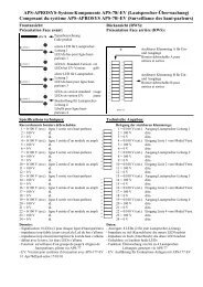
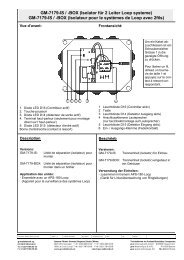
<strong>APS</strong>-<strong>APROSYS</strong>-<strong>System</strong>-<strong>Komponente</strong> <strong>APS</strong>-<strong>58</strong> (serielles Steuermodul)<br />
Composant du système <strong>APS</strong>-<strong>APROSYS</strong> <strong>APS</strong>-<strong>58</strong> (Module pour commandes serielles)<br />
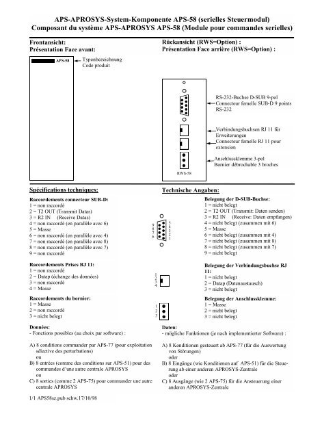
Frontansicht:<br />
Présentation Face avant:<br />
<strong>APS</strong>-<strong>58</strong><br />
Typenbezeichnung<br />
Code produit<br />
Rückansicht (RWS=Option) :<br />
Présentation Face arrière (RWS=Option) :<br />
Spécifications techniques: Technische Angaben:<br />
Raccordements connecteur SUB-D:<br />
1 = non raccordé<br />
2 = T2 OUT (Transmit Datas)<br />
3 = R2 IN (Receive Datas)<br />
4 = non raccordé (en parallèle avec 6)<br />
5 = Masse<br />
6 = non raccordé (en parallèle avec 4)<br />
7 = non raccordé (en parallèle avec 8)<br />
8 = non raccordé (en parallèle avec 7)<br />
9 = non raccordé<br />
Raccordements Prises RJ 11:<br />
1 = non raccordé<br />
2 = Datap (échange des données)<br />
3 = non raccordé<br />
4 = Masse<br />
Raccordements du bornier:<br />
1 = Masse<br />
2 = non raccordé<br />
3 = nicht belegt<br />
Données:<br />
- Fonctions possibles (au choix par software) :<br />
A) 8 conditions commander par <strong>APS</strong>-77 (pour exploitation<br />
sélective des perturbations)<br />
ou<br />
B) 8 entrées (comme des conditions sur <strong>APS</strong>-51) pour des<br />
commandes d’une autre centrale <strong>APROSYS</strong><br />
ou<br />
C) 8 sorties (comme 2 <strong>APS</strong>-75) pour commander une autre<br />
centrale <strong>APROSYS</strong><br />
1/1 <strong>APS</strong><strong>58</strong>sz.pub schw.17/10/98<br />
9<br />
8<br />
7<br />
6<br />
1<br />
2<br />
3<br />
4<br />
1<br />
2<br />
3<br />
5<br />
4<br />
3<br />
2<br />
1<br />
RWS-<strong>58</strong><br />
RS-232-Buchse D-SUB 9-pol<br />
Connecteur femelle SUB-D 9 points<br />
RS-232<br />
Verbindungsbuchsen RJ 11 für<br />
Erweiterungen<br />
Connecteur femelle RJ 11 pour<br />
extension<br />
Anschlussklemme 3-pol<br />
Bornier débrochable 3 broches<br />
Belegung der D-SUB-Buchse:<br />
1 = nicht belegt<br />
2 = T2 OUT (Transmit: Daten senden)<br />
3 = R2 IN (Receive: Daten empfangen)<br />
4 = nicht belegt (zusammen mit 6)<br />
5 = Masse<br />
6 = nicht belegt (zusammen mit 4)<br />
7 = nicht belegt (zusammen mit 8)<br />
8 = nicht belegt (zusammen mit 7)<br />
9 = nicht belegt<br />
Belegung der Verbindungsbuchse RJ<br />
11:<br />
1 = nicht belegt<br />
2 = Datap (Datenaustausch)<br />
3 = nicht belegt<br />
Belegung der Anschlussklemme:<br />
1 = Masse<br />
2 = nicht belegt<br />
3 = nicht belegt<br />
Daten:<br />
- mögliche Funktionen (je nach implementierter Software) :<br />
A) 8 Konditionen gesteuert ab <strong>APS</strong>-77 (für die Auswertung<br />
von Störungen)<br />
oder<br />
B) 8 Eingänge (wie Konditionen auf <strong>APS</strong>-51) für die Steue-<br />
rung ab einer anderen <strong>APROSYS</strong>-Zentrale<br />
oder<br />
C) 8 Ausgänge (wie 2 <strong>APS</strong>-75) für die Ansteuerung einer<br />
anderen <strong>APROSYS</strong>-Zentrale
<strong>APS</strong>-<strong>APROSYS</strong> <strong>System</strong> Component <strong>APS</strong>-<strong>58</strong> (Communication Module)<br />
Sistema <strong>APS</strong> <strong>APROSYS</strong> : MÓDULO DE CONTROL SERIE mod. <strong>APS</strong>-<strong>58</strong><br />
Front view:<br />
Vista frontal:<br />
<strong>APS</strong>-<strong>58</strong><br />
Rear view (RWS) :<br />
Vista posterior (RWS):<br />
Características técnicas: Technical Specifications:<br />
Datos:<br />
- Funciones posibles :<br />
A) 8 condiciones controladas desde el módulo <strong>APS</strong>-77 (p. ej.<br />
para la conmutación selectiva de amplificadores de<br />
reserva)<br />
o<br />
B) 8 entradas (como condiciones sobre <strong>APS</strong>-51) para el<br />
control desde otra central <strong>APROSYS</strong><br />
o<br />
C) 8 salidas (como 2 <strong>APS</strong>-75) para el control de otra central<br />
<strong>APROSYS</strong><br />
1/1 <strong>APS</strong><strong>58</strong>spe.pub schw.17/10/98<br />
Model code<br />
Código del producto<br />
Distribución del conector Sub D:<br />
1 = Libre<br />
2 = T2 OUT (transmisión de datos)<br />
3 = R2 IN (recepción de datos)<br />
4 = Libre (en conjunto con el pin 6)<br />
5 = Masa<br />
6 = Libre (en conjunto con el pin 4)<br />
7 = Libre (en conjunto con el pin 8)<br />
8 = Libre (en conjunto con el pin 7)<br />
9 = Libre<br />
Distribución del conector de enlace RJ 11:<br />
1 = Libre<br />
2 = Datap (Entrada/salida para datos serie)<br />
3 = Libre<br />
4 = Masa<br />
Distribución de la regleta de bornes:<br />
1 = Masa<br />
2 = Libre<br />
3 = Libre<br />
9<br />
8<br />
7<br />
6<br />
1<br />
2<br />
3<br />
4<br />
1<br />
2<br />
3<br />
5<br />
4<br />
3<br />
2<br />
1<br />
RWS-<strong>58</strong><br />
Data:<br />
- possible functions:<br />
RS-232 D-SUB 9-pole connector<br />
Conector hembra RS-232 Sub D<br />
de 9 vías<br />
Connector socket RJ 11<br />
(for expansions)<br />
Conector hembra de enlace RJ 11<br />
3-pole connector block<br />
Regleta de bornes, de 3 vías<br />
Connection di<strong>ag</strong>ram for the D-SUB socket:<br />
1 = Not connected<br />
2 = T2 OUT (Transmit Datas)<br />
3 = R2 IN (Receive Datas)<br />
4 = Not connected (together with pin 6)<br />
5 = Earth<br />
6 = Not connected (together with pin 4)<br />
7 = Not connected (together with pin 8)<br />
8 = Not connected (together with pin 7)<br />
9 = Not connected<br />
Connection di<strong>ag</strong>ram for the RJ 11 connector<br />
socket:<br />
1 = Not connected<br />
2 = Datap (Input/output for serial data)<br />
3 = Not connected<br />
Pin connections for 3-pole connector block:<br />
1 = Earth<br />
2 = Not connected<br />
3 = Not connected<br />
A) Control of 8 conditions from an <strong>APS</strong>-77 (for the selective<br />
evaluation of troubles)<br />
or<br />
B) 8 input channels (such as <strong>APS</strong>-51 conditions) for control by<br />
another <strong>APROSYS</strong>- central unit<br />
or<br />
C) 8 output channels (such as 2 <strong>APS</strong>-75) for controlling<br />
another <strong>APROSYS</strong> central unit.