manuale DIFFUSIONE BIG.pmd - KlimaShop!
manuale DIFFUSIONE BIG.pmd - KlimaShop!
manuale DIFFUSIONE BIG.pmd - KlimaShop!

You also want an ePaper? Increase the reach of your titles
YUMPU automatically turns print PDFs into web optimized ePapers that Google loves.
54<br />
13<br />
3<br />
3.1<br />
28<br />
I GB F D<br />
USO E MANUTENZIONE<br />
(parte utente)<br />
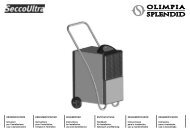
COMPONENTI DEL SISTEMA<br />
(fig. 28)<br />
Il sistema è composto da un’unità<br />
interna (climatizzatore) 1, da<br />
un’unità esterna 8 che contiene il<br />
compressore, il ventilatore, lo<br />
scambiatore di calore e dal telecomando<br />
per la gestione ed il controllo<br />
delle varie funzioni 9 (vedi par. 3.7<br />
Programmazione).<br />
Altre indicazioni:<br />
2 Griglia di aspirazione aria<br />
L’aria della stanza viene aspirata,<br />
passa attraverso i filtri interni che<br />
trattengono la polvere.<br />
3 Uscita aria<br />
L’aria trattenuta fuoriesce<br />
climatizzata dalla griglia inferiore.<br />
4 Tubi gas refrigerante<br />
L’unità esterna e interna sono<br />
collegate da tubi in rame<br />
all’interno dei quali circola il gas<br />
refrigerante.<br />
5 Tubo di scarico condensa<br />
L’umidità della stanza si<br />
condensa e si scarica da questo<br />
tubo all’esterno.<br />
6 Cavo alimentazione.<br />
7 Griglia fuoriuscita aria di<br />
condensa.<br />
2<br />
3<br />
9<br />
7<br />
8<br />
USE AND<br />
MAINTENANCE<br />
(by user)<br />
COMPONENTS OF THE<br />
SYSTEM (fig. 28)<br />
The system is composed of an inside<br />
unit (air-conditioner) 1, and outside<br />
unit 8 containing the compressor, fan,<br />
heat exchanger, and a remove control<br />
for the management and control of<br />
the functions 9 (see chap. 3.7<br />
Programming).<br />
Other information:<br />
2 Air intake<br />
The air in the room is drawn in,<br />
and passes through the filters that<br />
trap the dust.<br />
3 Air outlet<br />
The treated air is released through<br />
the bottom grating.<br />
4 Cooling gas pipes<br />
The outside and inside units are<br />
connected by copper pipes<br />
through which the cooling gas<br />
circulates.<br />
5 Condensation drain<br />
discharge<br />
The moisture in the room is<br />
condensed and drained through<br />
this pipe to the outside.<br />
6 Power cable<br />
7 Grating for outlet of<br />
condensation air<br />
OFF<br />
ON<br />
MODE D’EMPLOI ET<br />
ENTRETIEN<br />
(partie utilisateur)<br />
COMPOSANTS DU SYSTEME<br />
(fig. 28)<br />
Le système est composé d’une unité<br />
intérieure (climatiseur) 1, d’une unité<br />
extérieure 8 qui contient le<br />
compresseur, le ventilateur,<br />
l’échangeur de chaleur ainsi que de<br />
la télécommande pour la gestion et<br />
le contrôle des différentes fonctions<br />
9 (voir chap. 3.7 Programmation).<br />
Autres indications:<br />
2 Grille d’aspiration de l’air<br />
L’air de la pièce est aspiré, il passe<br />
à travers les filtres internes qui<br />
retiennent la poussière.<br />
3 Sortie de l’air<br />
L’air retenu sort climatisé par la<br />
grille inférieure.<br />
4 Tuyaux du gaz frigorigène<br />
L’unité extérieure et intérieure sont<br />
reliées par des tuyaux en cuivre à<br />
l’intérieur desquels circule le gaz<br />
frigorigène.<br />
5 Tuyau d’évacuation du<br />
condensat<br />
L’humidité de la pièce se condense<br />
et est évacuée vers l’extérieur par<br />
ce tuyau.<br />
6 Câble d’alimentation<br />
7 Grille sortie de l’air de<br />
condensation<br />
BEDIENUNG UND<br />
WARTUNG (Benutzer)<br />
SYSTEMKOMPONENTEN<br />
(Abb. 28)<br />
Das System besteht aus einer<br />
Inneneinheit (Klimagerät) 1, einer<br />
Außeneinheit 8, zu der ein<br />
Kompressor, ein Ventilator, ein<br />
Wärmetauscher und eine<br />
Fernbedienung zur Steuerung und<br />
Bedienung der verschiedenen<br />
Funktionen 9 gehören (siehe<br />
Abschnitt 3.7 Programmierung).<br />
Weitere Angaben:<br />
2 Luftansauggitter<br />
Die Raumluft wird angesaugt und<br />
strömt durch Innenfilter, die den<br />
Staub zurückhalten.<br />
3 Luftausströmung<br />
Die angesaugte Luft strömt<br />
klimatisiert aus dem unteren<br />
Gitter aus.<br />
4 Kühlrohre<br />
Die Außen- und Inneneinheit sind<br />
durch Kupferrohre verbunden, in<br />
denen das Kühlgas zirkuliert.<br />
5 Kondenswasserabflussrohr<br />
Die Raumfeuchtigkeit<br />
kondensiert und wird von diesem<br />
Abflussrohr nach außen<br />
abgeführt.<br />
6 Stromkabel<br />
7 Abluftgitter<br />
1<br />
4<br />
6<br />
5