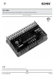
MI - Instrucciones instalador (789 kb) - Elvox.com
MI - Instrucciones instalador (789 kb) - Elvox.com
MI - Instrucciones instalador (789 kb) - Elvox.com

Create successful ePaper yourself
Turn your PDF publications into a flip-book with our unique Google optimized e-Paper software.
FL’appareil 887U est un interphone universel pouvant être utiliséindifféremment dans des systèmes traditionnels avec appel en C.A.ou dans des systèmes avec appel électronique du type SoundSystem. L'interphone universel étant <strong>com</strong>patible avec la plupart desinterphones en vente sur le marché mondial représente la solutionidéale pour remplacer un vieil appareil sans devoir intervenir surtoute l'installation. Pour effectuer les connexions et les réglages, voirle tableau de <strong>com</strong>patibilité à page 4. L'interphone est doté d'un boutonpour l'ouverture de la porte et d'un trimmer pour l'optimisationdu niveau du son sur le microtéléphone.ELVOX S.p.A. TIENT À PRÉCISER QUE sur des installations déjàexistantes, le niveau du son pourrait ne pas être optimal, aussi bienen transmission qu'en réception, en cas de présence d'autres appareilsdéfectueux qui maintiendraient inopportunément le pêne ouvert.RÉGLAGESPour effectuer les réglages, il est nécessaire d'accéder à la carteélectronique positionnée sur le fond métallique de l'appareil. Lesréglages consistent à positionner deux ponts afin de choisir le typed'appel et la référence <strong>com</strong>mune de l'installation. Pour optimiser leniveau du son interne du microtéléphone, intervenir sur les deuxtrimmers R1 et R2 à l'aide d'un tournevis.POSITIONNEMENT DU CÂBLE DE JONCTION POUR LASÉLECTION DE LA RÉFÉRENCE COMMUNESELEZIONE DEL RIFERIMENTO COMUNECommun COMUNE NEGATIVO négatifCommun COMUNE POSITIVO positif- C +- C +CÂBLE DE JONCTION APPEL ÉLECTRONIQUEPOSITIONNÉ ENTRE « E » et LE (INTERPHONES ELVOX technologieSound System)PEIGNE CENTRAL DU CONNEC-TEUR CN5 (fig. 1)CÂBLE DE JONCTIONAPPEL EN C. A.POSITIONNÉ ENTRE « C.A. » etLE PEIGNE CENTRAL DU CON-NECTEUR CN5 (fig. 1)RÉGLAGE COMMUN INSTALLATION (connecteur CN6)Suivre les indications du tableau ci-dessous pour sélectionner laréférence COMMUNE de l'installation. La référence <strong>com</strong>mune représentegénéralement le négatif (-), <strong>com</strong>me pour toutes les installationsELVOX, mais elle peut, dans certains cas, représenter le positif (+).CÂBLE DE JONCTION ENTRE « -» et « C » DU CONNECTEUR CN6(fig. 1)CÂBLE DE JONCTION ENTRE «+ » et « C » DU CONNECTEURCN6 (fig. 1)COMMUN NÉGATIF (-)COMMUN POSITIF (+)RÉGLAGE FIN DU VOLUME EXTERNE ET INTERNEÀ NOTER que le réglage primaire des niveaux sonores est principalementgéré par l'alimentateur et/ou par le poste externe téléphoniquede l'installation. Pour optimiser le niveau sonore sur lemicrotéléphone, agir sur les trimmers R1 et R2 (voir fig. 1). R1 permetd'optimiser le gain du microphone (VOL. EXT.), tandis que R2permet d'optimiser le niveau sonore du récepteur (VOL. INT.).Réglage fin duvolume interneREGOLAZIONE FINEDEL LIVELLO FONICORéglage findu volumeexterneREGOLAZIONE FINEDEL LIVELLO FONICVALEURS D'IMPÉDANCE DES HAUT-PARLEURSIMPÉDANCE HAUT-PARLEUR DE16 OHML'APPEL ÉLECTRONIQUEIMPÉDANCE HAUT-PARLEUR RÉGLABLE DE 16 OHMS À ENVI-<strong>MI</strong>CROTÉLÉPHONE RON 120 OHMS AU MOYEN DUTRIMMER R2TABLEAU DE COMPATIBILITÉ AVEC D'AUTRES ARTICLES ELVOXPOSITIONNEMENT POSIZIONAMENTO DU JUMPER CÂBLE PER DE LA JONCTION SELEZIONE DEL POUR LA SÉLECTION DU TYPE D'APPELTIPO DI CHIAMATA:Appel électroniqueCN4CN5CN6R1R2CHIAMATA ELETTRONICAbornier de connexionconnecteur pour la sélection du type d'appelponts pour la sélection du <strong>com</strong>mun positif ou négatiftrimmer pour le réglage du volume externetrimmer pour le réglage du volume interneBORNIER DE CONNEXION CN4EEC.AAppel c.a.CHIAMATA IN C.A.Fig. 1C.A1 haut-parleur2 microphone3 <strong>com</strong>mun6 appel7 gâcheRÉGLAGE TYPE D'APPEL (connecteur CN5)Suivre les indications du tableau ci-dessous pour sélectionner letype d'appel adapté à l'installation.L'appel en C.A. fonctionne avec un ronfleur tandis que l'appel électroniquefonctionne avec le haut-parleur du microtéléphone aurepos.MODÈLE BORNES DE CONNEXION TYPE APPELELVOX 1 2 3 6 7 É (voir schéma887Upage 6)C.A. (voirschéma page 7)ELVOX 1 2 3 6 7 C.A.8870ELVOX88751 2 3 6 7 ETABLEAU DE COMPATIBILITÉ AVEC LES MODÈLES D'AUTRESFABRICANTSÀ noter que le tableau suivant n'est fourni qu'à titre indicatif et qu'ilne <strong>com</strong>prend que certains modèles de quelques producteurs.Quoiqu'il en soit, il est généralement possible, en vue d'une installationcorrecte, de se référer aux schémas fournis aux pages suivanteset aux valeurs indiquées dans la section précédente « VALEURSD'IMPÉDANCE DES HAUT-PARLEURS ».La colonne “bornes de raccordement” indiquée dans la table à page17 indique le correct câblage à effectuer pendant le remplacementd’un appareil avec le poste d’appartement universel ELVOX Art.887U.PAR EXEMPLE, en cas de remplacement d'un interphone « ACET »,le câble qui se trouve dans la borne « 7 » doit être connecté à laborne « 1 » de l'interphone ELVOX 887U et le câble de la borne 10 àla borne 2 de l'interphone 887U, et ainsi de suite.La colonne « TYPE D'APPEL » indique le point de positionnement ducâble de jonction sur le connecteur CN5 (voir fig. 1) del'INTERPHONE UNIVERSEL ELVOX 887U.PAR EXEMPLE, en cas de remplacement d'un interphone « AUTATF92 », il est nécessaire de positionner, sur le connecteur CN5 (voirfig. 1) de l'INTERPHONE UNIVERSEL ELVOX 887U, un câble dejonction entre « E » et le peigne central.4
DDas Universal-Haustelefon Art. 887U kann ohne Unterschied inherkömmlichen Anlagen mit Wechselstromruf oder in Anlagen mitelektronischem Ruf vom Typ Sound System verwendet werden.Das Universal-Haustelefon ist mit den meisten auf dem Weltmarkterhältlichen Haustelefonen kompatibel, deshalb ist es die idealeLösung, um einen alten Apparat zu ersetzen, ohne die ganze Anlageumbauen zu müssen. Für die Durchführung der Anschlüsse undEinstellungen wird auf die Kompatibilitätstabelle auf Seite 4 verwiesen.Das Haustelefon ist mit Türöffner, und zur Optimierung derTonstufe am Hörer mit einem Trimmer ausgestattet.ELVOX S.p.A. WEIST AUSDRÜCKLICH DARAUF HIN, dass dieTonstufe sowohl in der Übertragung als auch im Empfang bei bereitsexistierenden Anlagen unter Umständen nicht optimal ist, wenn anderedefekte Apparate vorhanden sind, die den Hörer fälschlicherweiseabgehoben halten.EINRICHTEN UND EINSTELLENUm das Gerät einzurichten und einzustellen, ist der Zugang zurElektronikplatine an dessen Metallboden erforderlich. Das Einrichtenbesteht aus dem Anbringen von zwei Stec<strong>kb</strong>rücken, mit denen dieRufart und der gemeinsame Referenzkontakt der Anlage gewähltwird. Durch Verstellen der beiden Trimmer R1 und R2 mit einemSchraubenzieher kann die interne Tonstufe des Hörers optimiert werden.POSITIONIERUNG DES JUMPERS FÜR DIE WAHL DESGEMEINSAMEN REFERENZKONTAKTSSELEZIONE DEL RIFERIMENTO COMUNEGemeinsamer COMUNE NegativkontaktNEGATIVOGemeinsamer COMUNE PluskontaktPOSITIVO- C +- C +ZWISCHEN “E” UND DEM <strong>MI</strong>T-TLEREN KONTAKTFINGER DESSTECKVERBINDERS CN5 POSI-TIONIERTER JUMPER (Abb. 1)ZWISCHEN “AC” UND DEM <strong>MI</strong>T-TLEREN KONTAKTFINGER DESSTECKVERBINDERS CN5 POSI-TIONIERTER JUMPER (Abb. 1)ELEKTRONISCHER RUF(ELVOX HAUSTELEFONE mitSound System Technologie)WECHSELSTROMRUFALLGEMEINES EINRICHTEN DER ANLAGE (Steckverbinder CN6)Bei der Wahl des gemeinsamen Referenzkontakts der Anlage ist dienachstehende Tabelle zu befolgen. Im Allgemeinen ist die Referenzder Minuskontakt (-) wie bei allen Anlagen von ELVOX, aber in einigenFällen kann die Referenz auch der Pluskontakt (+) sein.JUMPER ZWISCHEN “-“ und “C”DES STECKVERBINDERS CN6(Abb. 1)JUMPER ZWISCHEN “+” und“C” DES STECKVERBINDERSCN6 (Abb. 1)GEMEINSAMERNEGATIVKONTAKT (-)GEMEINSAMER PLUSKONTAKT(+)FEINEINSTELLUNG DER AUSSEN- UND INNENLAUTSTÄRKEES IST ZU BEACHTEN, dass die primäre Einstellung der Tonstufenhauptsächlich vom Netzgerät und/oder von der externenAudiostelle der Anlage geregelt wird.Um die Tonstufe am Hörer zu optimieren, können die Trimmer R1und R2 verstellt werden (siehe Abb. 1). Mit R1 wird die Verstärkungdes Mikrofons optimiert (LAUTST. AUSSEN), mit R2 wird hingegendie Tonstufe des Hörers optimiert (LAUTST. INNEN).IMPEDANZWERTE DER LAUTSPRECHERFeineinstellungderREGOLAZIONE FINEInnenlautstärkeDEL LIVELLO FONICOPOSITIONIERUNG POSIZIONAMENTO JUMPER DES JUMPERS LA SELEZIONE FÜR DEL DIE WAHL DER RUFARTTIPO DI CHIAMATA:Elektronischer RufCN4CN5CN6R1R2CHIAMATA ELETTRONICACHIAMATA IN C.A.EEC.AC.AAnschlussklemmenleisteSteckverbinder für die Wahl der RufartFeineinstellungderAußenlautstärkeREGOLAZIONE FINEDEL LIVELLO FONICWechselstromruf Fig. 1Stec<strong>kb</strong>rücken für die Wahl des gemeinsamen Plus- bzw.NegativkontaktsTrimmer für die Regelung der AußenlautstärkeTrimmer für die Regelung der InnenlautstärkeANSCHLUSSKLEMMENLEISTE CN41 Lautsprecher2 Mikrofon3 Gemeinsamer Kontakt6 Ruf7 TürschlossEINRICHTEN DER RUFART (Steckverbinder CN5)Bei der Wahl der für die Anlage geeigneten Rufart ist die nachstehendeTabelle zu befolgen. Der Wechselstromruf verwendet einenSummer; der elektronische Ruf verwendet den Lautsprecher desHörers in Ruhestellung.LAUTSPRECHERIMPEDANZ16 OHMDES ELEKTRONISCHEN RUFSLAUTSPRECHERIMPEDANZ EINSTELLBAR VON 16 OHM BISAM HÖRERCIRCA 120 OHM <strong>MI</strong>TTELSTRIMMER R2KOMPATIBILITÄTSTABELLE <strong>MI</strong>T ANDEREN ARTIKELN VONELVOXMODELL ANSCHLUSSKLEMMEN RUFARTELVOX 1 2 3 6 7 E (siehe Schaltplan887Uauf Seite 6)AC (siehe Schaltplanauf Seite 7)ELVOX 1 2 3 6 7 C.A.8870ELVOX 1 2 3 6 7 E8875KOMPATIBILITÄTSTABELLE <strong>MI</strong>T DEN MODELLEN ANDERERHERSTELLERDie nachstehende Tabelle dient nur zur Orientierung und enthält nureinige Modelle einiger Hersteller. Für eine korrekte Installation kannim Allgemeinen auf die Schaltpläne der folgenden Seiten und aufdie im obigen Abschnitt “IMPEDANZWERTE DER LAUTSPRE-CHER” angegebenen Werte Bezug genommen werden. Die «Anschlussklemmen » Säule, die in Tabelle auf 17 Seite gezeigt ist,stellt die korrekte zu durchführende Verkabelung während derErsetzung eines Gerätes mit dem allgemeinen <strong>Elvox</strong> Art. 887U dar.Wenn ZUM BEISPIEL ein Haustelefon “ACET” ersetzt wird, ist dasKabel in Klemme “7” an der Klemme Nummer “1” des HaustelefonsELVOX 887U anzuschließen, das Kabel von Klemme 10 an derKlemme Nr. 2 des Haustelefons 887U und so weiter.In der Spalte “RUFART” ist angegeben, wo der Jumper amSteckverbinder CN5 (siehe Abb. 1) des UNIVERSAL-HAUSTE-LEFONS ELVOX 887U angebracht werden muss.Wenn ZUM BEISPIEL ein Haustelefon “AUTA TF92” ersetzt wird, istam Steckverbinder CN5 (siehe Abb. 1) des UNIVERSAL-HAUSTE-LEFONS ELVOX 887U ein Jumper zwischen “E” und dem mittlerenKontaktfinger anzubringen.5
EEl artículo 887U es un teléfono universal utilizable indiferentementeen las intalaciones de tipo tradicional con llamada en C.A. o en lasinstalaciones con llamada electrónica de tipo Sound System. Elteléfono universal es <strong>com</strong>patible con la mayor parte de los teléfonospresentes en el mercado mundial, por esta razón representa la soluciónideal en el remplazo de un aparato viejo sin tener que interveniren toda la instalación. Para efectuar el conexionado y las programacionesver el prospecto de <strong>com</strong>patibilidad a página 4. El teléfono esdotado de un pulsador abrepuerta , de un trimmer para poder optimizarel nivel fónico en el microteléfono.ELVOX S.p.A. PRECISA QUE en instalaciones ya existentes el nivelfónico, sea en la transmisión que en la recepción, podría no resultaroptimal si hay otros aparatos defectuosos que mantienen inoportunamenteel gancho abierto.PROGRAMACIONES Y REGULACIONESPara efectuar las programaciones y las regulaciones es necesarioacceder a la ficha electrónica que se encuentra en el fondo metálicodel aparato. Las programaciones consisten en el posicionamiento dedos puentes para escoger el tipo de llamada y la referencia <strong>com</strong>únde la instalación. Obrando con un destornillador en los dos trimmersR1 y R2 es posible optimizar el nivel fónico interno del microteléfono.POSICIONA<strong>MI</strong>ENTO DEL PUENTE PARA LA SELECCIÓNDE LA REFERENCIA COMÚNSELEZIONE DEL RIFERIMENTO COMUNEComún positivoCOMUNE NEGATIVO- C +Común COMUNE POSITIVO negativo- C +Puente posizionado entre “E” y el Llamada electrónicacentral del conector CN5 (Fig.1 ) (TELÉFONOS ELVOX, tecnología“SOUND SYSTEM”)Puente posicionado entre “C.A.” Llamada en C.A.y el central del conectorCN5 (Fig. 1)PROGRAMACIÓN COMÚN DE LA INSTALACIÓN (conector CN6)Para la selección de la referencia COMÚN de la instalación seguir elprospecto indicado a continuación. Generalmente la referencia<strong>com</strong>ún es el negativo (-), <strong>com</strong>o para todas las instalaciones ELVOX,pero, en algunos casos, la referencia puede ser positiva (+).Puente entre “-“ y “C” del conectorCN6 (Fig. 1).Puente entre “+” y “C” del conectorCN6 (Fig. 1)Común negativo (-)Común positivo (+)REGULACIÓN FIN DEL VOLUMEN EXTERNO E INTERNOSE PRECISA que la regulación primaria de los niveles fónicos esprincipalmente administrada por el alimentador y/o por el aparatoexterno fónico de la instalación. Para optimizar el nivel fónico en elmicroteléfono es posible obrar en los trimmers R1 y R2 (Ver Fig. 1).Con R1 se optimiza la ganancia del microteléfono (VOL. ESTERNO)(Volumen externo) mientras con R2 se optimiza el nivel fónico delreceptor (VOL. INT.) (Volumen interno).VALORES DE IMPEDENCIA DE LOS ALTAVOCESRegulación findel volumeninternoREGOLAZIONE FINEDEL LIVELLO FONICORegulaciónfin del volumenexterno.REGOLAZIONE FINEDEL LIVELLO FONICIMPEDENCIA ALTAVOZ DE LALLAMADA ELECTRÓNICA.IMPEDENCIA ALTAVOZ DEL<strong>MI</strong>CROTELÉFONOOHM POR MEDIO DELTRIMMER R216 OHMREGULABLE DE 16 OHM ACERCA 120PROSPECTO DE COMPATIBILIDAD CON OTROS ARTÍCULOSELVOXPOSICIONA<strong>MI</strong>ENTO POSIZIONAMENTO DEL JUMPER PUENTE PER LA SELEZIONE PARA LA DEL SELECCIÓN DEL TIPO DE LLAMADATIPO DI CHIAMATA:Llamada electrónicaCN4CN5CN6R1R2CHIAMATA ELETTRONICALlamada en c.a.CHIAMATA IN C.A.EEC.AC.Aregleta de conexionadoconector para la selección del tipo de llamadapuentes para la selección del <strong>com</strong>ún positivo o negativotrimmer para la regulación del volumen externotrimmer para la regulación del volumen internoREGLETA DE CONEXIONES CN41 altavoz2 micrófono3 <strong>com</strong>ún6 llamada7 cerraduraFig. 1PROGRAMACIÓN TIPO DE LLAMADA (conector CN5)Para seleccionar el tipo de llamada adapto a la instalación seguir elprospecto indicado a continuación.La llamada C.A. utiliza un zumbador; la llamada electrónica utiliza elaltavoz del microteléfono en estado de reposo.MODELO BORNES DE CONEXIONADO TIPO DE LLAMADAELVOX887U1 2 3 6 7 E (ver esquema apág. 6)C.A. (ver esquemapág. 7)ELVOX 1 2 3 6 7 C.A.8870ELVOX88751 2 3 6 7 EPROSPECTO DE COMPATIBILIDAD CON LOS MODELOS DEOTROS PRODUCTORESSe precisa que el prospecto siguiente es solamente indicativo y<strong>com</strong>prende sólo algunos modelos de algunas casas productoras.De todas maneras para una correcta instalación se puede en generalhacer referencia a los equemas indicados en las páginas quesiguen y a los valores indicados en la sección precedente “VALO-RES DE IMPEDENCIA DE LOS ALTAVOCES”.La columna „bornes de conexión“ indicada en el prospecto de página17 indica el correcto cableado que hay que efectuar durante elremplazo de un aparato con el teléfono universal ELVOX Art. 887U.POR EJEMPLO, si se está remplazando un teléfono “ACET”, elcable conectado al borne número “7” debe conectarse al bornenúmero “1” del teléfono ELVOX 887U, el cable del borne 10 debeconectarse al borne 2 del teléfono 887U, y así adelante.La columna “TIPO DE LLAMADA” indica donde se ha de posicionarel puente en el conector CN5 (ver Fig. 1) del TELÉFONO UNIVER-SAL ELVOX 887U.POR EJEMPLO si se está remplazando un teléfono “AUTA TF92”,en el conector CN5 (ver Fig. 1) del TELEFONO UNIVERSAL ELVOX887U se ha de colocar el puente entre “E” y el peine central.6
PO artigo 887U é um telefone universal que pode ser utilizado, indiferentemente,em instalações do tipo tradicional <strong>com</strong> chamada emC.A., ou em instalações <strong>com</strong> chamada electrónica tipo SoundSystem. O telefone universal é <strong>com</strong>patível <strong>com</strong> a maior parte dostelefones existentes no mercado mundial, pelo que representa asolução ideal para substituir um velho aparelho sem ter de intervir narestante instalação. Para efectuar as ligações e as programaçõesconsultar a tabela de <strong>com</strong>patibilidade na pág. 4. O telefone estáequipado <strong>com</strong> um botão do trinco, um potenciómetro para poderoptimizar o nível do áudio no microtelefone.A ELVOX S.p.A. INFPORMA QUE, em instalações já existentes, onível do áudio, tanto na transmissão <strong>com</strong>o na recepção, poderá nãoser o ideal se existirem outros aparelhos defeituosos que mantenham,inoportunamente, o gancho aberto.PROGRAMAÇÕES E REGULAÇÕESPara efectuar as programações e as regulações é necessário acederà placa electrónica situada na base metálica do aparelho. As programaçõesconsistem no posicionamento de duas pontes a final deescolher o tipo de chamada e a referência <strong>com</strong>um da instalação.Actuando <strong>com</strong> uma chave de parafusos nos dois potenciómetro R1 eR2 é possível optimizar o nível do áudio interno do microtelefone.POSICIONAMENTO DA PONTE PARA A SELECÇÃO DAREFERÊNCIA COMUMRegulaçãofinal do volumeinternoREGOLAZIONE FINEDEL LIVELLO FONICOSELEZIONE DEL RIFERIMENTO COMUNEComum negativoCOMUNE NEGATIVOComum positivoCOMUNE POSITIVO- C +- C +Regulaçãofinal do volu-REGOLAZIONE FINEme externoDEL LIVELLO FONICPONTE SITUADA ENTRE “E” CHAMADA ELECTRÓNICAe A CENTRAL DO CONEC- (TELEFONES ELVOX tecnologiaSound System)TOR CN5 (fig. 1)PONTE SITUADA ENTRE CHAMADA EM C. A.“C.A.” e A CENTRAL DOCONECTOR CN5 (fig. 1)PROGRAMAÇÃO COMUM DA INSTALAÇÃO (conectorCN6)Seguir a tabela apresentada a seguir para a selecção dareferência COMUM da instalação. Geralmente a referência<strong>com</strong>um é o negativo (-), <strong>com</strong>e para todas as instalaçõesELVOX, porém nalguns casos, a referência pode ser o positivo(+).PONTE ENTRE “-“ e “C” DOCONECTOR CN6 (fig. 1)PONTE ENTRE “+” e “C” DOCONECTOR CN6 (fig. 1)COMUM NEGATIVO (-)COMUM POSITIVO (+)REGULAÇÃO FINAL DO VOLUME EXTERNO E INTERNOINFORMA-SE que a regulação primária dos níveis do áudioé gerida, principalmente, pelo alimentador e/ou pelo postoáudio externo da instalação.Para optimizar o nível do áudio no microtelefone é possívelactuar nos potenciómetros R1 e R2 (ver fig. 1). Com R1optimiza-se o ganho do microfone (VOL. EST.), enquantoque <strong>com</strong> R2 optimiza-se o nível do áudio do receptor (VOL.INT.).VALORES DA IMPEDÂNCIA DOS ALTIFALANTESIMPEDÂNCIA DOALTIFALANTE DACHAMADA ELECTRÓNICA16 OHMPOSICIONAMENTO DA PONTE PARA A SELECÇÃO DO TIPO DE CHAMADAPOSIZIONAMENTO JUMPER PER LA SELEZIONE DELTIPO DI CHIAMATA:Chamada electrónicaCHIAMATA ELETTRONICAChamada c.a.CHIAMATA IN C.A.E C.AE C.AFig. 1IMPEDÂNCIA DOALTIFALANTE DO<strong>MI</strong>CROTELEFONEREGULÁVEL DE 16 OHM ACERCA DE 120 OHMATRAVÉS DOPOTENCIÓMETRO R2CN4CN5CN6R1R2régua de bornes de ligaçãoconector para a selecção do tipo de chamadapontes para a selecção do <strong>com</strong>um positivo ou negativopotenciómetro para a regulação do volume externopotenciómetro para a regulação do volume internoRÉGUA DE BORNES DE LIGAÇÃO CN41 altifalante2 microfone3 <strong>com</strong>um6 chamada7 trincoPROGRAMAÇÃO DO TIPO DE CHAMADA (conector CN5)Seguir a tabela apresentada a seguir para seleccionar o tipo de chamadaque melhor se adapta à instalação. A chamada em C.A. utilizaum besouro; a chamada electrónica utiliza o altifalante do microtelefoneem repouso.7
MODELLI ALTRI PRODUTTORI MORSETTI DI COLLEGAMENTO TIPO CHIAMATAOTHER MANUFACTURERS' MODELS CONNECTION TER<strong>MI</strong>NALS CALL TYPEMODÈLES AUTRES FABRICANTS BORNES DE CONNEXION TYPE APPELMODELLE ANDERER HERSTELLER ANSCHLUSSKLEMMEN RUFARTMODELOS DE OTROS PRODUCTORES BORNES DE CONEXIONADO TIPO DE LLAMADAELVOX 887U 1 2 3 6 7 C.A./EACET 7 10 2 9 5 C.A.AUTA 7 3 4 12 10 C.A.AUTA TF92 7 3 4 12 10 EBITRON 1 2 6 C7 9 EBPT 8 - 5 7 9 EBPT 5 1 4 3 2 C.A.CITOVOX 7 10 9 T 5 C.A.COFREL (LT TERRANEO) 3 4 1 5 6 ECOFREL 600 (LT TERRANEO) 2 1 3 6 T1 C.A.COFREL 603 (LT TERRANEO) 2 6 3 6 T C.A.COMELIT VOX ART. 2100-2101-2102-2103-2104 2 3 4 S/1 P1 C.A.:2100-02-03, E:2101-04COMELIT CIAO ART. 2300-01-02-04 2 3 4 S/1 P1 ECOMELIT OKAY ART. 2402W -04W - 05W 2 3 4 S P1 EELBEX SPE <strong>MI</strong>C LOW + C.A.FARFISA 2 1 3 6 5 C.A.FERMAX GONDOLA 2 1 3 V/5 4 C.A.FERMAX REKTO TF-4 B A C E P C.A.FERMAX 2044, 20440, 21100 6 2 3 4 1 EGOLMAR S M A N X C.A./ EGOLMAR 10 5 3 7 C2 EGOLMAR 4 5 3 12 11 C.A.GOLMAR T-600 2 1 3 6 T C.A.GOLMAR T810B 10 5 3 7 P1 C.A.GOLMAR T-2800 10 5 3 7 4 C.A.SAFNAT 3 1 2 V 4 C.A.SELTI 2 1 3 6 5 C.A.SIEDLE HT611-01 11 2 9/C 7 1 C.A.SPRINT 2 1 3 6 / C.A.TEGUI GL 5 4 2 1 3 C.A.TEGUI HORIZON 5 4 2 1 3 C.A./ ETELEVES 1 2 3 T 4 C.A.TESLA DDZ 85 6 2 3 4 1 C.A.TESLA DDZ 93 6 2 3 4 Z C.A.URMET 1 2 6 7 8 C.A.URMET 1 2 6 7 9 C.A.URMET DOMUS 1131 1 2 10 4 9 C.A.URMET DOMUS 1130 2 1 3 4 5 C.A.VIDEX 2 1 7 6 5 C.A.Sezione conduttori - Conductor sectionSections des conducteurs-LeiterquerschnittSecciones conductores-Secção condutoresConduttori-Conductors Ø fino a 50m-Ø up to 50m Ø fino a 100m-Ø up to 100m Ø fino a 200m-Ø up to 200mConductors-Leitungslänge Ø jusqu’à 50m-Ø bis 50m Ø jusqu’à 100m.-Ø bis 100m Ø jusqu’à 200m.-Ø bis 200mConductores-Condutores Øhasta 50m - até 50m Ø hasta 100m - até 100m Ø hasta 200m - Ø até 200mComune e serraturaCommon and lockCommun et gâcheGemeinsame und Türöffner 0,5 mm 2 0,75 mm 2 1,5 mm 2Común y cerraduraCommun e trincoAltri-Others-AutresAndere-Otros-Outros 0,25 mm 2 0,5 mm 2 1 mm 28
SCHEMA DI COLLEGAMENTO IMPIANTO CITOFONICO CON ALIMENTATORE ART. 0831 E CITOFONO UNIVERSALEART. 887U.WIRING DIAGRAM OF AUDIO ENTRY SYSTEM WITH POWER SUPPLY UNIT ART. 0831 AND UNIVERSAL INTERPHONEART. 887UANSCHLUSSPLAN FÜR SPRECHANLAGE <strong>MI</strong>T NETZGERÄT ART. 0831 UND UNIVERSAL-HAUSTELEFON ART. 887USCHÉMA DE CONNEXION POSTE INTERPHONE AVEC ALIMENTATEUR ART. 0831 ET INTERPHONE UNIVERSEL ART.887UCITOFONO - PHONEPOSTE - HAUSTELEFONTELÉFONO - TELEFONEART. 887UCH S3 2 1ESQUEMA DE CONEXIONADO PARA PORTERO ELÉCTRICO CONALIMENTADOR ART. 0831 Y TELÉFONO UNIVERSAL ART. 887U.ESQUEMA DE LIGAÇÃO UMA INSTALAÇÃO DE PORTEIROELÉCTRICO COM ALIMENTADOR ART. 0831 E TELEFONE UNIVERSALART. 887U.CN6+C-EC.A.CN5CITOFONO - PHONEPOSTE - HAUSTELEFONTELÉFONO - TELEFONEART. 887U12367SETTAGGIO JUMPERS “CN5-CN6”C+ IMPIANTO CITOFONICO CON COMUNE POSITIVO (MORSETTO 3)C- IMPIANTO CITOFONICO “ELVOX” O CON COMUNE NEGATIVO (MORSETTO 3)SETTAGGIO JUMPERS “CN5-CN6”E IMPIANTO CITOFONICO CON SISTEMA DI CHIAMATA ELETTRONICA (SOUND SYSTEM)C.A. IMPIANTO CITOFONICO CON SISTEMA DI CHIAMATA C.A.SETTING OF JUMPERS “CN5-CN6”C+ AUDIO ENTRY SYSTEM WITH POSITIVE COMMON (TER<strong>MI</strong>NAL 3)C- “ELVOX” AUDIO ENTRY SYSTEM WITH NEGATIVE COMMON (TER<strong>MI</strong>NAL 3)SETTING OF JUMPERS “CN5-CN6”E AUDIO ENTRY SYSTEM WITH ELECTRONIC CALL SYSTEM (SOUND SYSTEM)AC AUDIO ENTRY SYSTEM WITH AC CALL SYSTEMCN6+C-EC.A.CN512367RÉGLAGE CÂBLES DE JONCTION « CN5-CN6»C+ POSTE INTERPHONE AVEC COMMUNPOSITIF (BORNE 3)C- POSTE INTERPHONE « ELVOX » OUAVEC COMMUN NÉGATIF (BORNE 3)RÉGLAGE CÂBLES DE JONCTION « CN5-CN6»É POSTE INTERPHONE AVEC SYSTÈMED'APPEL ÉLECTRONIQUE (SOUNDSYSTEM)C.A. POSTE INTERPHONE AVEC SYSTÈMED'APPEL C.A.CH CH CH S 3 2 1RETE-MAINSRÉSEAU-NETZRED-REDEPRI1 2 3 6 7 8 15 10 0ALIMENTATOREPOWER SUPPLYALIMENTATIONNETZGERÄTALIMENTADORArt. 0831EINRICHTEN DER JUMPER “CN5-CN6”C+ SPRECHANLAGE <strong>MI</strong>T GEMEINSAMEMPLUSKONTAKT (KLEMME 3)C- SPRECHANLAGE “ELVOX” ODER <strong>MI</strong>T NEGA-TIVKONTAKT (KLEMME 3)EINRICHTEN DER JUMPER “CN5-CN6”E SPRECHANLAGE <strong>MI</strong>T ELEKTRONISCHEMRUFSYSTEM (SOUND SYSTEM)AC SPRECHANLAGE <strong>MI</strong>T WECHSELSTROM-RUFPROGRAMACIÓN PUENTES “CN5-CN6”C+ INSTALACIÓN PORTEROELÉCTRICO CON COMÚNPOSITIVO (BORNE 3).C- INSTALACIÓN PORTEROELÉCTRICO ”ELVOX” O CONCOMÚN NEGATIVO (BORNE3).PROGRAMACIÓN PUENTES “CN5-CN6”E INSTALACIÓN PORTEROELÉCTRICO CON SISTEMADE LLAMADA ELCTRÓNICA(SOUND SYSTEM)C.A. INSTALACIÓN PORTEROELÉCTRICO CON SISTEMADE LLAMADA C.A.N° SI223AL1D345678CBA- Targa con posto esternoEntrance panelPlaque de rue avec poste externeKlingeltableau mit SprechstellePlaca con aparato externoBotoneira <strong>com</strong> posto externoserie-série 1200, 1300, 3300, 80008100, PATAVIUMB- Pulsante supplementare ser ra tu raAdditional push-button for lockPoussoir supplémentaire gâchezusätzliche TüröffnertastePulsador suplementario cerraduraBotão suplementar de trincoC- Serratura elettricaElectric lockGâche électriqueElektrischer TüröffnerCerradura eléctricaTrinco eléctrico 12V∼D- Posto esterno - Outdoor unitPoste externe - SprechstelleAparato externo - Posto esternoArt. 0930/000.04 - 930AL1-Lampada luce targaBulb for panel lightingLampe d’éclairage plaqueBirne für TastenbeleuchtungLámpara luz escaleraLâmpada da luz da botoneira(3x24V 3W max.)10x24V 3W con/with Art. M83216X24V 3W con/with Art. 0832/03010
I GB FAVVERTENZE PER L'INSTALLATORE- Leggere attentamente le av ver ten ze contenutenel pre sen te do cu men to in quanto for ni sco noimportanti indicazioni ri guar dan ti la sicurezza diin stal la zio ne, d'uso e di ma nu ten zio ne.- Dopo aver tolto l'imballaggio assicurarsidell'integrità del l'ap pa rec chio. Gli ele men ti dell'imballaggio(sacchetti di pla sti ca, po li sti ro loespanso, ecc.) non devono essere lasciati allaportata dei bambini in quanto potenziali fonti dipericolo. L'esecuzione dell'impianto deve essereri spon den te alle nor me CEI vigenti.- È necessario prevedere a monte dell'alimentazioneun appropriato in ter rut to re di tipo bipolarefacilmente accessibile con separazione tra icontatti di almeno 3mm.- Prima di col le ga re l'apparecchio ac cer tar si che idati di targa siano rispondenti a quelli della rete didi stri bu zio ne.- Questo ap pa rec chio dovrà essere de sti na to soloall'uso per il quale è stato espres sa men te concepito,e cioè per sistemi di citofonia. Ogni altrouso è da con si de rar si im pro prio e quindi pericoloso.Il costruttore non può essere con si de ra tore spon sa bi le per even tua li danni derivanti da usiimpropri, erronei ed ir ra gio ne vo li.- Prima di ef fet tua re qual si a si operazione di pu li zia odi ma nu ten zio ne, disinserire l'apparecchio dalla retedi ali men ta zio ne elettrica, spe gnen do l'interruttoredel l'im pian to.- In caso di guasto e/o di cattivo fun zio na men todel l'ap pa rec chio, togliere l'ali men ta zio ne me -dian te l'interruttore e non ma no met ter lo. Perl'even tua le ri pa ra zio ne ri vol ger si so la men te ad uncentro di assistenza tecnica autorizzato dalcostruttore. Il mancato ri spet to di quanto so prapuò <strong>com</strong> pro met te re la si cu rez za del l'ap pa rec -chio.- Non ostru i re le aperture o fessure di ven ti la zio neo di smaltimento calore e non esporrel’apparecchio a stillicidio o spruzzi d’acqua.- L'installatore deve as si cu rar si che le in for ma zio niper l'uten te siano pre sen ti sugli ap pa rec chiderivati.- Tutti gli apparecchi costituenti l'impianto devonoessere de sti na ti esclu si va men te all'uso per cui sonostati con ce pi ti.- ATTENZIONE: per evitare di ferirsi, questoapparecchio deve essere assicurato alla parete secondole istruzioni di installazione.- Questo do cu men to dovrà sem pre ri ma ne reallegato alla do cu men ta zio ne dell'impianto.Direttiva 2002/96/CE (WEEE, RAEE).Il simbolo del cestino barrato riportato sull’apparecchioindica che il prodotto, allafine della propria vita utile, dovendo esseretrattato separatamente dai rifiuti domestici,deve essere conferito in un centro diraccolta differenziata per apparecchiature elettricheed elettroniche oppure riconsegnato al rivenditore almomento dell’acquisto di una nuova apparecchiaturaequivalente.L’utente è responsabile del conferimento dell’apparecchioa fine vita alle appropriate strutture di raccolta.L’adeguata raccolta differenziata per l’avviosuccessivo dell’apparecchio dismesso al riciclaggio,al trattamento e allo smaltimento ambientalmente<strong>com</strong>patibile contribuisce ad evitare possibili effettinegativi sull’ambiente e sulla salute e favorisce ilriciclo dei materiali di cui è <strong>com</strong>posto il prodotto.Per informazioni più dettagliate inerenti i sistemi diraccolta disponibili, rivolgersi al servizio locale dismaltimento rifiuti, o al negozio in cui è stato effettuatol’acquisto.Rischi legati alle sostanze considerate pericolose(WEEE).Secondo la nuova Direttiva WEEE sostanze che datempo sono utilizzate <strong>com</strong>unemente su apparecchielettrici ed elettronici sono considerate sostanzepericolose per le persone e l’ambiente. L’adeguataraccolta differenziata per l’avvio successivo dell’apparecchiodismesso al riciclaggio, al trattamento eallo smaltimento ambientalmente <strong>com</strong>patibile contribuiscead evitare possibili effetti negativi sull’ambientee sulla salute e favorisce il riciclo dei materialidi cui è <strong>com</strong>posto il prodotto.SAFETY INSTRUCTIONS FOR INSTALLERS- Carefully read the instructions on this leaflet: theygive important information on the safety, use andmaintenance of the installation.- After removing the packing, check the integrity ofthe set. Packing <strong>com</strong>ponents (plastic bags,expanded polystyrene etc.) are dangerous forchildren. Installation must be carried out accordingto national safety regulations.- It is convenient to fit close to the supply voltagesource a proper bipolar type switch with 3 mmseparation (minimum) between contacts.- Before connecting the set, ensure that the dataon the label correspond to those of the mains.- Use this set only for the purposes designed,i.e.for electric door-opener systems. Any otheruse may be dangerous. The manufacturer is notresponsible for damage caused by improper,erroneous or irrational use.- Before cleaning or maintenance, disconnect theset.- In case of failure or faulty operation, disconnectthe set and do not open it.- For repairs apply only to the technical assistancecentre authorized by the manufacturer.- Safety may be <strong>com</strong>promised if these instructionsare disregarded.- Do not obstruct opening of ventilation or heatexit slots and do not expose the set to drippingor sprinkling of water.- Installers must ensure that manuals with theabove instructions are left on connected unitsafter installation, for users' information.- All items must only be used for the purposesdesigned.WARNING: to avoid the possibility of hurting yourself,this unit must be fixed to the wall according tothe installation instructions.- This leaflet must always be enclosed with theequipment.Directive 2002/96/EC (WEEE)The crossed-out wheelie bin symbolmarked on the product indicates that atthe end of its useful life, the product mustbe handled separately from householdrefuse and must therefore be assigned to a differentiatedcollection centre for electrical and electronicequipment or returned to the dealer upon purchaseof a new, equivalent item of equipment.The user is responsible for assigning the equipment,at the end of its life, to the appropriate collectionfacilities.Suitable differentiated collection, for the purpose ofsubsequent recycling of de<strong>com</strong>missioned equipmentand environmentally <strong>com</strong>patible treatment anddisposal, helps prevent potential negative effects onhealth and the environment and promotes the recyclingof the materials of which the product is made.For further details regarding the collection systemsavailable, contact your local waste disposal serviceor the shop from which the equipment was purchased.Risks connected to substances considered asdangerous (WEEE).According to the WEEE Directive, substances sincelong usually used on electric and electronicappliances are considered dangerous for peopleand the environment. The adequate differentiatedcollection for the subsequent dispatch of theappliance for the recycling, treatment and dismantling(<strong>com</strong>patible with the environment) help to avoidpossible negative effects on the environment andhealth and promote the recycling of material withwhich the product is <strong>com</strong>pound.CONSEILS POUR L'INSTALLATEUR- Lire attentivement les instructions contenuesdans ce document puisqu'elles fournissentd'importantes indications concernant la sécuritépour l'installation, l'emploi et la maintenance.- Après avoir enlevé l'emballage s'assurer del'intégrité de l'appareil. Les éléments del'emballage (sachets en plastique, polystyrène,etc.) ne doivent pas être laissés à la portée desenfants, car ils peuvent être dangereux.L'exécution de l'installation doit être conformeaux normes nationales.- Il est nécessaire de prévoir près de la sourced’alimentation un interrupteur approprié, typebipolaire, avec une separation entre les contactsd’au moins 3mm.- Avant de connecter l'appareil s'assurer que lesdonnées reportées sur l'étiquette soient lesmêmes que celles du réseau de distribution.- Cet appareil devra être destiné uniquement àl'emploi pour lequel il a été expressément conçu,c'est-à-dire pour l'alimentation des systèmes deportiers électriques. Tout autre emploi doit être considéréimpropre et donc dangereux. Le constructeurne peut pas être considéré responsable pourd'éventuels dommages résultant de l'emploi impropre,erroné et déraisonnable.- Avant d'effectuer n'importe quelle opération denettoyage ou de maintenance, débrancherl'appareil du réseau d'alimentation électrique, enéteignant l'interrupteur de l'installation.- En cas de pan ne et/ou de mauvais fonctionnementde l'appareil, enlever l'alimentation aumoyen de l'interrupteur et ne pas le modifier.- Pour une éventuelle réparation s'adresser uniquementà un centre d'assistance technique autorisépar le constructeur. Si on ne respecte pas lesinstructions mentionnées ci-dessus on peut <strong>com</strong>promettrela sécurité de l'appareil.- Ne pas obstruer les ouvertures et les fentes deventilation ou de refroidissement et ne pas exposerl’appareil à l’égout ou jet d’eau.- L'installateur doit s'assurer que les renseignementspour l'usager soient présents dans lesappareils connectés.- Tous les appareils constituant l'installationdoivent être destinés exclusivement à l'emploipour lequel ils ont été conçus.- ATTENTION: pour éviter de se blesser, cet appareildoit être assuré au mur selon les instructionsd’installation.- Ce document devra être toujours joint avecl'appareillage.Directive 2002/96/CE (WEEE, RAEE)Le symbole de panier barré se trouvant surl'appareil indique que le produit, à la fin desa vie utile, doit être traité séparément desautres déchets domestiques et remis à uncentre de collecte différencié pour appareils électriqueset électroniques ou remis au revendeur au moment del'achat d'un nouvel appareil équivalent.L’usager est responsable du traitement de l'appareilen fin de vie et de sa remise aux structures de collecteappropriées. La collecte différenciée pour ledémarrage successif de l’appareil remis au recyclage,au traitement et à l'élimination éco<strong>com</strong>patiblescontribue à éviter les effets négatifs environnementauxet sur la santé tout en favorisant le recyclagedes matériaux dont se <strong>com</strong>pose le produit. Pour desinformations plus détaillées sur les systèmes de collectedisponibles, contacter le service locald'élimination des déchets ou le magasin qui a vendul'appareil.Risques liés aux substances considérées dangéreuses(WEEE).Selon la Directive WEEE, substances qui sont utiliséesdepuis long temps habituellement dans desappareils électriques et électroniques sont consideréesdangéreuses pour les personnes etl'environnement. La collecte sélective pour le transfertsuivant de l’équipement destiné au recyclage,au traitement et a l’écoulement environnemental<strong>com</strong>patible contribue à éviter possibles effets négatifssur l’environnement et sur la salue et favorise lerecyclage des matériaux dont le produit est <strong>com</strong>posé.11
DANWEISUNGEN FÜR DEN INSTALLATEUR- Diese Anweisungen genau lesen, da sie über dieSicherheit beim Einbau, den Gebrauch und Pflegeinformieren.- Nach dem Auspacken die Unversehrtheit desGeräts feststellen.- Es ist notwendig bei derSpannungversorgungquelle einen pasendenzweipoligen Schalter einzuschalten, der eine 3 mm(minimum) Trennung zwischen Kontakts habenmuß.- Die Anlage muß den nationalen Normenentsprechen.- Es ist notwendig vor dem Netzgerät einenpassenden Shutz-und Trennschalter einzubauen.Vor dem Anschließen des Geräts sich versichern,daß die Daten des Klingeltableaus mit denen imLeitungsnetz überein stimmen.- Dieses Gerät nur für den vorbestimmten Gebrauchverwenden, und zwar für die Stromsversorgung vonTürsprechanlagen. Jeder andere Gebrauch istgefährlich. Der Hersteller nimmt keineVerantwortung für beim Mißbrauch des Geräts entstandenenSchaden.- Vor jeglicher Säuberung oder Nachpflege, Gerätvom Versorgungsnetz abschalten (Schaltknopfdrücken).- Im Falle einer Beschädigung und/oder schlechtenFunktionierens des Geräts dieses durchVersorgungsnetzschalter abschalten.- Für die eventuelle Reparatur sich an eine offizielletechnische Kundenbetreuungsstelle wenden. DieMißachtung dieses Hinweises könnte die Sicherheitdes Geräts gefährden.- Keine Lüftung- oder Hitzungschlitze des Geräts verschließenund das Gerät nicht an Tropfen oderWasserstrahl bringen.- Der Installateur muß nach dem Einbau darauf achten,daß die Anweisungen für den Benutzer immervorhanden sind.- Alle Geräte dürfen nur für den vorbestimmtenGebrauch verwendet werden.- VORSICHT: um eine Verletzung zu vermeiden, diesesGerät an die Wand wie nach Anleitungsanweisungeninstallieren.- Dieses Blatt muß den Geräte immer beigelegt werden.Richtlinie 2002/96/EG (WEEE)Das am Gerät angebrachte Symbol des durchgestrichenenAbfallkorbs bedeutet, dassdas Produkt am Ende seiner Lebenszeit vomHausmüll getrennt zu entsorgen ist, undeiner Müllsammelstelle für Elektro- undElektronik-Altgeräte zugeführt, oder bei Kauf einesneuen gleichartigen Geräts dem Händler zurückgegebenwerden muss.Der Benutzer ist dafür verantwortlich, dass das Gerätam Ende seiner Nutzungsdauer zu den entsprechendenSammelstellen gebracht wird. Die korrektegetrennte Sammlung des Geräts für seine anschließendeZuführung zum Recycling, zur Behandlungund zur umweltgerechten Entsorgung trägt dazu bei,mögliche negative Auswirkungen auf die Umwelt undauf die Gesundheit zu vermeiden und begünstigt dieWiederverwertung der Werkstoffe des Produkts. Fürgenauere Informationen über die verfügbarenSammelsysteme wenden Sie sich bitte an den örtlichenMüllsammeldienst oder an den Händler, bei demSie das Gerät gekauft haben.Risikos, die als gefährlichen gehalteten Stoffenentsprechen (WEEE).Gemäss die Richtlinien WEEE, Stoffe, die bei elektrischenund elektronischen Anlagen schon langeverwendet werden, wie gefählich für die Personnenund für die Umwelt behalten werden mussen. Dieangemessene unterschiedene Sammlung für die folgendeÜbertragung des für den Abfall, Behandlungund Verdauung abgelegten Gerätes kompatibel derUmwelt hilft mögliche negative Wirkungen zu vermeidenüber die Umwelt und die Gesundheit und begünstigtdas Recycling vom Materialen, deren der Produkthergestellt ist.ECUIDADOS A TER PELO INSTALADOR- Ler atentamente as advertências contidas nopresente do cu men to que fornecem importantesindicações no que diz respeito à segurança dainstalação, ao uso e à manutenção.- Após retirar a embalagem, assegurar-se da integridadedo aparelho. Todos os elementos da embalagem(sacos plásticos, esferovite, etc.) ñao devemser deixados ao alcance de crianças pois sãofontes potenciais de perigo. A execução da instalaçãodeve respeitar a regulamentação vigente nopaís.- É necessàrio instalar, perto da fuente de alimentação,um interruptor apropriado, do tipo bipolar,<strong>com</strong> uma separação minima de 3 mm entre oscontactos.- Antes de ligar o aparelho verificar se os dados daplaca estão de acordo <strong>com</strong> os da rede de distribuição.- Este aparelho só deve ser destinado ao uso para oqual foi expressamente concebido, isto é, para alimentaçãode porteiro eléctrico.Qualquer outra utilização deve ser consideradaimprópria e por conseguinte perigosa. O construtornão pode ser considerado responsável poreventuais danos provocados por usos impróprios,errados e irracionáveis.- Antes de efectuar qualquer operação de limpezaou de manutenção, desligar o aparelho da rede dealimentação eléctrica através do di spo si ti vo instalado.- No caso de dano e/ou mau funcionamento doaparelho, eliminar a alimentação da rede atravésdo dispositivo de corte e mantê-lo desligado. Parauma eventual reparação recorrer sòmente a umcentro de assistência técnica autorizado pelo construtor.O não cumprimento de tudo quanto anteriormentese disse pode <strong>com</strong>prometer a segurançado aparelho.- Não obstruir as aberturas ou ranhuras de ventilaçãoou de dissipação de calor e não expor oaparelho ao estilicidio du pulverização de agua.- O <strong>instalador</strong> deve assegurar-se de que as informaçõespara o utilizador estão presentes nos aparelhos.- Todos os aparelhos que constituem a instalaçãodevem ser destinados exclusivamente ao uso parao qual foram concebidos.- ATTENCIÓN: Para evitar de herirse, este aparatodebe ser fijado a la pared según las instruciones deinstalación.- Este documento deverá estar sempre junto ao aparelho.Norma 2002/96/CE (WEEE, RAEE)O símbolo do cêsto barrado referido noaparelho indica que o producto, no fim dasua vida útil, tendo que ser tratado separadamentedos refugos domésticos, deve serentregado num centro de recolha diferenciadapara aparelhagens eléctricas e electrónicas oureconsignado ao revendedor no momento de aquisiçãodum novo aparelho equivalente.El usuario es responsable de entregar el aparato a unpunto de recogida adecuado al final de su vida.La recogida diferenciada de estos residuos facilita elreciclaje del aparato y de sus <strong>com</strong>ponentes, permitesu tratamiento y eliminación de forma <strong>com</strong>patiblecon el medio ambiente y previene los efectos negativosen la naturaleza y la salud de las personas. Sidesea obtener más información sobre los puntos derecogida, contacte con el servicio local de recogidade basura o con la tienda donde adquirió el producto.Perigos referidos à substancias consideradasperigosas (WEEE).Según a Directiva WEEE, subtáncias que desde hátempo utilizam-se <strong>com</strong>unemente nos aparelhos eléctricose eléctrónicos são consideradas substánciasperigosas para as pessoas e o ambiente. A dequadacolecção diferenciada para o envio seguinte da aparelhagemdeixada de usar para a reciclagem, ao tratamentoe à eliminação ambientalmente <strong>com</strong>patívelcontribui a evitar possíveis efectos negativos noambiente e na saude e favorece o reciclo dos materiaisdos quais o producto é <strong>com</strong>posto.PCONSEJOS PARA EL INSTALADOR- Leer atentamente los consejos contenidos en elpresente documento en cuanto dan importantesindicaciones concernientes la seguridad de lainstalación, del uso y de la manutención.- Después de haber quitado el embalaje asegurarsede la integridad del aparato.- Los elementos del embalaje (bolsos de plásticoetc.) no tienen que ser dejados al alcance de losniños en cuanto posibles fuentes de peligro.La ejecución de la instalación, debe respetar lasnormas en vigor.- Es necesário instalar cerca la fuente de alimentaciónun interruptor apropiado, de tipo bipolar,con una separación entre los contactos de almenos 3mm.- Antes de conectar el aparato asegurarse que losdatos de la placa sean iguales a los de la red dedistribución.- Este aparato tendrá que ser destinado solamenteal uso para el cual fue expresamente concebido,es decir para alimentación de sistemas de porteroeléctrico.Los otros usos deben ser considerados impropiosy por lo tanto peligrosos.El constructor no puede ser considerado responsablede eventuales daños causados por usosimpropios erróneos e irrazonables.- Antes de efectuar cualquiera operación delimpieza o de manutención, desconectar el aparatode la red de alimentación eléctrica, apagando elinterruptor de la instalación.- En caso de daño y/o de malo funcionamiento delaparato, quitar la alimentación por medio del interruptory no manipularlo.Para eventuales reparaciones recurrir solamente aun centro de asistencia técnica autorizado por elconstructor. La falta de respeto a lo anteriormenteexpuesto puede <strong>com</strong>prometer la seguridad delaparato.- No obstruir las aberturas o hendiduras de ventilacióno de salida calor.- El <strong>instalador</strong> debe asegurarse que las informacionespara el usuario sean presentes en losaparatos derivados.- Todos los aparatos que constituyen la instalacióndeben ser destinados exclusivamente al uso parael qual fueron concebidos.- ATENÇÃO: Para evitar ferir-se, este aparelho deveser fixado na parede de acordo <strong>com</strong> as instruções deinstalação.- Este documento tendrà que ser siempre adjuntadoal aparato.Directiva 2002/96/CE (WEEE, RAEE)El símbolo del cubo de basura tachado,presente en el aparato, indica que éste, alfinal de su vida útil, no debe desecharsejunto con la basura doméstica sino quedebe llevarse a un punto de recogida diferenciadapara aparatos eléctricos y electrónicos oentregarse al vendedor cuando se <strong>com</strong>pre un aparatoequivalente.El usuario es responsable de entregar el aparato a unpunto de recogida adecuado al final de su vida.La recogida diferenciada de estos residuos facilita elreciclaje del aparato y de sus <strong>com</strong>ponentes, permitesu tratamiento y eliminación de forma <strong>com</strong>patible conel medio ambiente y previene los efectos negativosen la naturaleza y la salud de las personas. Si deseaobtener más información sobre los puntos de recogida,contacte con el servicio local de recogida debasura o con la tienda donde adquirió el producto.Riesgos conectados a sustancias consideradaspeligrosas (WEEE).Según la Directiva WEEE, substancias que desdetiempo son utilizadas conmunemente en aparatoseléctricos ed electrónicos son consideradas substanciaspeligrosas para las personas y el ambiente. Laadecuada colección diferenciada para el siguienteenvio del aparato destinado al reciclaje , tratamientoy eliminación ambientalmente <strong>com</strong>patible contribuyea evitar posibles efectos negativos sobre el ambientey la salud y favorece el reciclo de los materiales que<strong>com</strong>ponen el producto.FILIALI ITALIATorinoStrada del Drosso, 33/810135 TorinoMilanoVia Conti Biglia, 220162 MilanoELVOX Costruzioni elettroniche S.p.A. - ITALYVia Pontarola, 14/a - 35011 Campodarsego (Padova)Tel 049 9202511 - Fax 049 9202603 - info@elvox.<strong>com</strong>Telefax Export Dept. +39/049 9202601 - elvoxexp@elvox.<strong>com</strong>FILIALI ESTEREELVOX Austria GmbHGrabenweg 67A-6020 InnsbruckELVOX Shanghai Electronics Co. LTDRoom 2616, No. 325 Tianyaoqiao RoadXuhui District200030 Shanghai Cinawww.elvox.<strong>com</strong>CERT n° 9110.ELVOUNI EN ISO 9001:200812