Gas-Gebläsebrenner Forced draught gas burner ... - Riello Burners
Gas-Gebläsebrenner Forced draught gas burner ... - Riello Burners
Gas-Gebläsebrenner Forced draught gas burner ... - Riello Burners

Create successful ePaper yourself
Turn your PDF publications into a flip-book with our unique Google optimized e-Paper software.
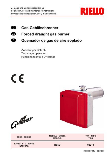
Montage und BedienungsanleitungInstallation, use and maintenance instructionsInstrucciones de instalación, uso y mantenimientoDGBE<strong>Gas</strong>-Gebläsebrenner<strong>Forced</strong> <strong>draught</strong> <strong>gas</strong> <strong>burner</strong>Quemador de <strong>gas</strong> de aire sopladoZweistufiger BetriebTwo stage operationFuncionamiento a 2 a llamasCODE - CÓDIGOMODELL - MODELMODELOTYP - TYPETIPO3762012 - 37620163762058RS5D922T12903087 (4) - 09/2009
2.3 ARBEITSFELD, (nach EN 676)8,0Druck im Feuerraummbar6,44,83,21,6D43570150170 190 210 230 250 270 290 310 330 350kW130.000 170.000 210.000 250.000290.000 kcal/hBrennerleistungPRÜFKESSELDas Arbeitsfeld wurde an einem Prüfkessel, gemäß der Norm EN 676, ermittelt.HANDELSÜBLICHE HEIZKESSELDie Abstimmung Brenner-Kessel ist ohne Probleme, wenn der Kessel der Euronorm EN 303 entspricht unddie Abmessungen des Feuerraumes mit Euronorm EN 676 übereinstimmen.Wenn der Brenner mit einem Heizkessel kombiniert werden soll, der nicht der Euronorm EN 303 und derEN 676 entspricht, müssen die technischen Daten aufeinander abgestimmt werden. Die Kesseldaten beimHersteller abfragen.VOM GASDRUCK AM BRENNERKOPF ABHÄNGIGE BRENNERLEISTUNGBei einem an dem Verbindungsrohr (M2, siehe Kap. 3.5, Seite 6) gemessenen Druck von 10,7 mbar, mit einemfeuerraumseitigen Druck von 0 mbar und mit <strong>Gas</strong> G20 - unterer Heizwert = 10 kWh/m 3 (8.570 kcal/m 3 ), erreichtman die Höchstleistung.1110<strong>Gas</strong>druck im mbaram Brennerkopf9876543D44362150 170 190 210 230 250 270 290 310 330 350130.000 170.000 210.000 250.000 290.000BrennerleistungkWkcal/h30874 D
3. INSTALLATIONDIE INSTALLATION DES BRENNERS MUSS IN ÜBEREINSTIMMUNG MIT DEN ÖRTLICHEN GESETZENUND VORSCHRIFTEN AUSGEFÜHRT WERDEN.3.1 BETRIEBSPOSITIONDer Brenner ist ausschließlich fürden Betrieb in Position 1 vorbereitet.Installationen in den Positionen 2,3, 5, 6, 7 können den korrektenBetrieb des Geräts beeinträchtigen,da sie die Schließung derLuftklappe in Ruhestellung nichtgewährleisten.ist nur mit dem "Kit MULTIBLOC-Rotation” möglich, der gesondertbestellt werden muss. Die Installationin Position 4 ist aus Sicherheitsgründenuntersagt.1 2 3 45 6 7D44503.2 BRENNERMONTAGEZur Installation des Brenners am Heizkessel sind folgende Vorgänge auszuführen: Falls erforderlich, die Bohrungen der Isolierdichtung (3, Abb. 3) erweitern. Mit den Schrauben (4) (falls erforderlich) den Muttern (2) an der Kesseltür (1) den Flansch (5) mit Isolierdichtung(3) montieren, aber eine der zwei höheren Schrauben losschrauben (siehe Abb. 2). Den Verbrennungskopf des Brenners an dem Flansch einsetzen (5), den Flansch mit der Schraube (6)anziehen und dann die Schraube (4) blockieren, die losschraubt war.Anmerkung: Der Brenner kann mit dem veränderlichen Maß (A) befestigt werden (siehe Abb. 4).Der Verbrennungskopf soll die ganze Stärke der Kesseltür durchgehen.Abb. 2612Abb. 3D5012453Abb. 4A225÷ 203S7741D435830875 D
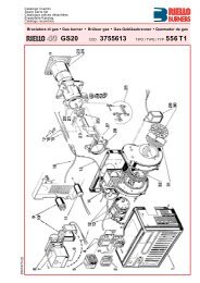
3.3 GASSTRECKEN, (nach EN 676)Die <strong>Gas</strong>strecke muß der Euronorm EN 676 entsprechen und wird extra bestellt. Die Einregulierung wirdentsprechend der beigefügten Betriebsanleitung durchgeführt.GASSTRECKEANSCHLÜSSETYP CODE EINGANG AUSGANGGEBRAUCHMB-ZRDLE 410 B01 3970542 Rp 1” 1/4 Flansch 3 Erd<strong>gas</strong> ≤ 200kW und Flüssig<strong>gas</strong> 160 ÷ 345 kWMB-ZRDLE 412 B01 3970543 Rp 1” 1/4 Flansch 3 Erd<strong>gas</strong> ≤ 300 kWMB-ZRDLE 415 B01 3970582 Rp 1” 1/2 Flansch 3 Erd<strong>gas</strong> ≥ 300 kW3.4 STROMVERSORGUNG DER GASARMATURDie Stromkabel für die <strong>Gas</strong>armatur können an der rechtenoder linken Brennerseite eingeführt werden, wie aufAbbildung 5 gezeigt.Je nach der Seite, an der die Stromkabel eingeführt werden,müssen die Kabelklemme mit <strong>Gas</strong>druckentnahmestelle(1) sowie die Kabelklemme (2) umgekehrt werden.Daher ist folgendes zu überprüfen: ob die Kabelklemme (1) korrekt positioniert ist; ob das Rohr korrekt positioniert ist, um Drosselungen zuvermeiden und zu verhindern, dass Luft zum Druckwächterströmen kann.ACHTUNGDas Rohr, falls nötig, auf das gewünschte Maß zuschneiden.Abb. 51 22D711313.5 GASANSCHLUSS–SCHEMAAbb. 61 2 3 M1 4 5 6 7 8M21 – <strong>Gas</strong>zuleitung2 – Handabsperrschieber (Sonderzubehör)3 – <strong>Gas</strong>druckmanometer (Sonderzubehör)4 – Filter5 – <strong>Gas</strong>druckwächter6 – Sicherheitsventil7 – <strong>Gas</strong>druckregler8 – Einstellventil 1. und 2. StufeM1 – Messung, AnschlußdruckM2 – Messung, Brenner- KopfdruckD520830876 D
3.6 ELEKTRISCHES VERDRAHTUNGSSCHEMA3.6.1 ELEKTRISCHES STANDARDVERDRAHTUNGSSCHEMASTEUERGERÄTMG569WERKSSEITIGEEINSTELLUNGVOM INSTALLATEURAUSZUFÜHRENHauptschalter230V ~ 50HzD7198ACHTUNG: Nullleiter nicht mit Phase austauschen;sich genau an das angegebeneSchema halten und eine guteZEICHENERKLÄRUNGB5 – 2. Stufe Betrieb-Fernmeldung S3 – Störabschaltung-FernmeldungC – Kondensator(230V - 0,5 A max.)CN1 – Kabelverbinder Flammenfühler T6A – SicherungE – ZündelektrodeTB – Brenner-Erdungh1 – 1. Stufe Stundenzähler TL – Begrenzungsthermostath2 – 2. Stufe Stundenzähler TR – 2. Stufe ThermostatM – MotorTS – SicherheitstemperaturbegrenzerPA – Minimalluftdruckwächter V10 – SicherheitsventilPG – Minimal<strong>gas</strong>druckwächter V11 – 1. Stufe VentilRS – FernentstörungV12 – 2. Stufe VentilSM – Luftklappen-Stellantrieb X.. – SteckerSO – FlammenfühlerXP.. – SteckdoseErdung ausführen. Der Leiterquerschnitt muss mindestens 1 mm 2 sein.(Außer im Falle anderslautender Angaben durch Normen und örtliche Gesetze). Die vom Installateur ausgeführten elektrischen Verbindungen müssen den lokalen Bestimmungen entsprechen. Den Thermostaten der 2. Stufe (TR) an den Klemmen T6 - T8 anschließen und die Überbrückung entfernen.PRÜFUNG Das Anhalten des Brenners überprüfen, indem die Thermostate geöffnet werden. Die Störabschaltung des Brenners überprüfen, indem der Verbinder (CN1) geöffnet wird, der sich am rotenDraht des Fühlers außen am Steuergerät befindet.ANMERKUNGENDas bedeutet, dass sie mindestens 1 Mal alle 24 Stunden anhalten müssen, damit das elektrische Steuergerät eineKontrolle seiner Effizienz beim Anfahren ausführen kann. Gewöhnlich wird das Anhalten des Brenners durch denBegrenzungsthermostat (TL) des Heizkessels gewährleistet. Sollte dies nicht der Fall sein, muss ein Zeitschalter mit(TL) seriengeschaltet werden, der für das Anhalten des Brenners mindestens einmal alle 24 Stunden sorgt.30877 D
3.6.2 ELEKTRISCHES VERDRAHTUNGSSCHEMA MIT DICHTHEITSKONTROLLE DER VENTILE(DUNGS VPS 504)230V ~ 50HzDen Thermostaten der 2. Stufe an den Klemmen T6 - T8 anschließenund die Überbrückung entfernen.D4371VOM INSTALLATEURAUSZUFÜHRENZEICHENERKLÄRUNGB5 – 2. St.Störabschaltung-Fernmeldungh1 – 1. St. Stundenzählerh2 – 2. St. StundenzählerPG – <strong>Gas</strong>druckwächterS3 – Störabschaltung-Fernmeldung(230V - 0,5 A max.)T6A –SicherungTL – BegrenzungsthermostatTR – 2. St. BegrenzungsthermostatTS – SicherheitstemperaturbegrenzerV10 – SicherheitsventilV11 –1. St.ventilV12 –2. St.ventilX4 – 4 - poliger SteckerX6 – 6 - poliger SteckerX7 – 7 - poliger SteckerAbb. 7STEUERGERÄT, (siehe Abb. 7)Um das Steuergerät aus dem Brenner zu nehmen, ist folgendes notwendig: alle an ihm angeschlossenen Verbinder, den 7-poligen Stecker,die Hochspannungskabel und den Erdleiter (TB) abnehmen; die Schraube (A, Abb. 7) losschrauben und das Steuergerät inPfeilrichtung ziehen.Für die Installation des Steuergeräts ist folgendes notwendig: die Schraube (A) mit einem Anzugsmoment von 1 ÷ 1,2 Nm anschrauben; alle vorher abgetrennten Verbinder wieder anschließen.AE9250IONISATIONSSTROMDer Betrieb des Steuergerätes erfordert einen Ionisationsstromvon mindenstens 5 µA.Da unter normalen Bedingungen ein weitaus höhereStrom erzeugt wird, sind normalerweise keine Kontrollennötig. Wenn aber der Ionisationsstromgemessen werden soll, muß der in dem roten Kabelgeschaltete Kabelverbinder (CN1) geöffnet und einGleichstrom - Mikroamperemeter (siehe Abb. 7) zwischengeschaltetwerden.+CN1D4631_Abb. 8SO30878 D
4. BETRIEBZÜNDLEISTUNGDie Zündung Muß mit reduzierter Leistung undnicht über 120 kW gescheben.– Den Verbinder (CN1) vom Kabel der Ionisationssondeabtrennen (siehe Elektrisches Verdrahtungsschemaauf Seite 7); der Brennerschaltet ein und geht nach der Sicherheitszeit(3s) in Störabschaltung.– 10 Zündungen mit darauffolgenden Störabschaltungendurchführen.– Am Zähler den gesamten <strong>Gas</strong>verbrauch ablesen.Dieser muß die folgenden Werte:0,10 Nm 3 bei G20 (Erd<strong>gas</strong> H)0,10 Nm 3 bei G25 (Erd<strong>gas</strong> L)0,03 Nm 3 bei G31 (Flüssig<strong>gas</strong>)nicht überschreiten.Abb. 94.1 EINSTELLUNG DER BRENNERLEI-STUNGIn Konformität mit der Wirkungsgradrichtlinie92/42/EWG müssen die Anbringung des Brennersam Heizkessel, die Einstellung und die Inbetriebnahmeunter Beachtung der Betriebsanleitung desHeizkessels ausgeführt werden, einschließlich Kontrolleder Konzentration von CO und CO 2 in denAb<strong>gas</strong>en, der Ab<strong>gas</strong>temperatur und der mittlenenKesseltemperatur.Entsprechend der gewünschten Kesselleistungwerden die Einstellung des Brennkopfes und derLuftklappe bestimmt.SW1019Der Brenner wird für die minimale Leistung imWerk eingestellt.4.2 BRENNERKOPFEINSTELLUNG,(siehe Abb. 9)Sie ist vom <strong>Gas</strong>durchsatz abhängig und wird ausgeführt,indem man die Einstellschraube (6) imUhrzeigersinn oder entgegen dem Uhrzeigersinnsoweit dreht , bis die auf der Einstellspindel markierteRaste (2) mit der Kante am Kopf (1).In der Abbildung 9 wird der Kopf für eine Leistungvon 230 kW eingestellt. Die Raste 4 der Einstellspindelstimmt mit der äußeren Fläche überein,wie im Diagramm gezeigt.Beispiel:Der Brenner wird in einem Heizkessel von210 kW installiert. Mit einer Leistung von 90%muß der Brenner ca. 230 kW liefern. Aus demDiagramm entsteht, daß die Einstellung für dieseLeistung auf der Raste 4 ausgeführt werden muß.kcal/h290,000270,000250,000230,000210,000190,000170,000150,000kW350330310290270250230210190170D4437ANMERKUNGDas Diagramm ist nur orientierend; nach KesselundBetriebsbedingungen können abweichendeEinstellungen erfordlich sein.130,0001500 2 4 6 810Raste30879 D
4.5 FÜHLER - UND ELEKTRODENSTELLUNG, (siehe Abb. 11)Abb. 113,5 ± 0,312ACHTUNGDas Einfügen der Platte (1) in der Abflachung derElektrode (2) nachprüfen.31 ± 0,3TASSEELEKTRODED4020PLATTEFÜHLERDen Isolator des Fühlers an die Tasse lehnen4.6 LUFTDRUCKWÄCHTERDie Einstellung des Luftdruckwächters erfolgt nach allen anderen Brennereinstellungen; der Druckwächter wirdauf den Anfangswert eingestellt.Bei Brennerbetrieb mit der geforderten Leistung, den Drehknopf langsam im Uhrzeigersinn drehen, bis eineStörabschaltung des Brenners erfolgt. Dann den Drehknopf gegen den Uhrzeigersinn um etwa 20% deseingestellten Wertes zurückdrehen und danach das korrekte Anfahren des Brenners überprüfen. Sollte derBrenner wieder in Störabschaltung gehen, den Drehknopf noch etwas gegen den Uhrzeigersinn drehen.Der Brenner wird mit dem Pressostat zu Beginn der Skala im Werk eingestellt.Achtung:Als Regel gilt, daß der Luftdruckwächter verhindern muß, daß der Luftdruck unter 80% des eingestelltenWertes sinkt und daß das CO im Ab<strong>gas</strong> 1% (10.000 ppm) überschreitet.Um das sicherzustellen, ein Ab<strong>gas</strong>analysegerät in den Kamin einfügen, die Ansaugöffnung des Gebläseslangsam schließen (zum Beispiel mit Pappe) und prüfen, daß die Störabschaltung des Brenners erfolgt,bevor das CO in den Ab<strong>gas</strong>en 1% überschreitet.4.7 BETRIEBSABLAUFNormalThermostatMotorZündtransformator1. Stufe Ventil1. Stufe Flamme1. Stufe Ventil2. Stufe FlammeStörabschaltungStörabschaltungwegen NichtzündungA40s min.3 ÷ 8s40s min.3s max.D50163s max.AWird durch die Kontrollampe am Steuer- und Überwachungsgerät signalisiert (4, Abb. 1, Seite 2).308711 D
4.8 WIEDERANLAUFFUNKTIONDas Steuergerät ermöglicht den erneuten Anlauf bzw. die vollständige Wiederholung des Anfahrprogrammsfür max. 3 Versuche, falls die Flamme während des Betriebs erlischt.4.9 NACHBELÜFTUNGSFUNKTIONDie Nachbelüftung ist eine Funktion, mit der die Belüftung auch nach dem Ausschalten des Brenners stattfindet.Das Ausschalten des Brenners erfolgt bei der Öffnung des Begrenzungsthermostaten (TL) mit folglicherUnterbrechung der Brennstoffzufuhr der Ventile.Um diese Funktion zu benutzen, muss die Entstörtaste betätigt werden, wenn der Begrenzungsthermostat(TL) nicht umgeschaltet ist (BRENNER AUS).Die Nachbelüftungszeit kann wie folgt auf max. 6 Minuten eingestellt werden: Mindestens 5 Sekunden lang auf die Entstörtaste drücken, bis die Anzeige-LED rot leuchtet. Die gewünschte Zeit durch mehrmaligen Druck auf die Taste einstellen: 1 Mal = 1 Minute Nachbelüftung. Nach 5 Sekunden wird das Steuergerät durch das Blinken der roten LED automatisch die eingestelltenMinuten anzeigen: 1 Mal Blinken = 1 Minute Nachbelüftung.Zur Rückstellung dieser Funktion genügt es, 5 Sekunden mindestens, bis die Anzeige-LED rot wird auf dieTaste zu drücken und diese loszulassen, ohne andere Handlungen auszuführen; danach vor dem erneutenAnfahren des Brenners mindestens 20 Sekunden.Sollte während der Nachbelüftung eine neue Wärmeanfrage erfolgen, so unterbricht sich die Nachbelüftungszeitbei der Umschaltung des Begrenzungsthermostaten (TL) und es beginnt ein neuer Betriebszyklusdes Brenners. Das Steuergerät wird werkseitig mit folgender Einstellung geliefert:0 Minuten = keine Nachbelüftung.4.10 ENTSTÖRUNG DES STEUERGERÄTSZur Entstörung des Steuergeräts ist wie folgt vorzugehen: Mindestens 1 Sekunde lang auf die Entstörtaste drücken.Sollte der Brenner nicht wieder anfahren, muss die Schließung des Begrenzungsthermostaten (TL)überprüft werden.5. WARTUNGVor der Durchführung von Reinigungs- oder Kontrollarbeiten, immer die elektrische Versorgungzum Brenner durch Betätigung des Hauptschalters der Anlage abschalten und das <strong>Gas</strong>absperrventilschließen.Der Brenner bedarf regelmäßiger Wartung, die von autorisiertem Personal und in Übereinstimmung mit örtlichenGesetzen und Vorschriften ausgeführt werden muss.Die regelmäßige Wartung ist für den korrekten Betrieb des Brenners von grundlegender Wichtigkeit; man vermeidetauf diese Weise unnützen Brennstoffverbrauch und verringert die Schadstoffemissionen in die Umwelt.DIE AUSZUFÜHRENDEN HAUPTARBEITEN SIND:Abb. 12 In regelmäßigen Abständen die Löcher am <strong>Gas</strong>verteiler auf Verstopfungenüberprüfen und gegebenenfalls mit einem geeignetenWerkzeug reinigen, wie auf der Abbildung 12 gezeigt. Prüfen, dass die Brennerzu- und –rückleitungen die Luftansaugzonenund die Leitungen, durch welche die Verbrennungsprodukteausgestoßen werden, keine Verstopfungen oderDrosselungen aufweisen. Die korrekte Durchführung der elektrischen Anschlüsse desBrenners und der <strong>Gas</strong>strecke überprüfen. Die korrekte Positionierung der Luftdruckanschluß überprüfen(9, Abb. 9, Seite 9). Prüfen, ob sich die <strong>Gas</strong>strecke für das Potential des Brenners,den benutzten <strong>Gas</strong>typ und den <strong>Gas</strong>druck des <strong>Gas</strong>netzeseignet.E9252 Die korrekte Positionierung des Flammkopfes und dessen Befestigung am Heizkessel überprüfen. Die korrekte Positionierung der Luftklappe überprüfen.308712 D
Die korrekte Positionierung des Ionisationsfühlers und der Elektrode überprüfen (Abb. 11, Seite 11). Die Einstellung des Luft- und des <strong>Gas</strong>druckwächters überprüfen.Den Brenner ca. 10 Minuten auf Vollbetrieb halten und die korrekten Eichungen in der 1. und 2. Stufe aller invorliegender Anleitung angegebenen Elemente überprüfen.Dann eine Verbrennungsanalyse ausführen, mit Überprüfung von: CO2 Anteil (%); CO Gehalt (ppm); NOx Gehalt (ppm); Ionisationsstrom (µA). Temperatur der Ab<strong>gas</strong>e zum Kamin.5.1 VISUELLE DIAGNOSTIK DES STEUERGERÄTSDas mitgelieferte Steuergerät hat eine Diagnosefunktion, um die eventuellen Ursachen von Betriebsstörungenzu ermitteln (Anzeige: ROTE LED).Um diese Funktion zu benutzen, muss mindestens 3 Sekunden lang ab dem Augenblick der Störabschaltungauf die Entstörtaste gedrückt werden.Das Steuergerät erzeugt eine Impulssequenz, die sich konstant alle 2 Sekunden wiederholt.ROTE LED leuchtetEntstörtaste 3s drückenBlinkenPause2sBlinken Die Sequenz der vom Steuergerät abgegebenen Impulse gibt die möglichen Defekte an, die in der nachfolgendenTabelle verzeichnet sind.2 Blinken3 Blinken4 BlinkenSIGNAL6 Blinken7 BlinkenMÖGLICHE URSACHEAm Ende der Sicherheitszeit wird keine stabile Flamme aufgenommen :– Defekt am Ionisationsfühler;– Defekt an den <strong>Gas</strong>ventilen;– Umkehrung von Phase/Nullleiter;– Defekt am Zündtransformator;– Brenner nicht eingestellt (<strong>Gas</strong> nicht ausreichend).Minimalluftdruckwächter schließt nicht oder ist vor dem Schließen des Begrenzungsthermostatenbereits geschlossen:– Defekt am Luftdruckwächter;– Luftdruckwächter schlecht eingestellt.Licht in der Brennkammer vor dem Einschalten und beim Ausschalten desBrenners:– Vorhandensein von Fremdlicht vor oder nach der Umschaltung des Begrenzungsthermostaten;– Vorhandensein von Fremdlicht während der Vorbelüftung;– Vorhandensein von Fremdlicht während der Nachbelüftung.Verlust an Belüftungsluft:– Luftverlust während der Vorbelüftung;– Luftverlust während oder nach der Sicherheitszeit.Erlöschen der Flamme während des Betriebs:– Brenner nicht eingestellt (<strong>Gas</strong> nicht ausreichend);– Defekt an den <strong>Gas</strong>ventilen;– Kurzschluss zwischen Ionisationsfühler und Erde.ACHTUNGUm das Steuergerät nach der Anzeige der Diagnostik rückzustellen, muss auf die Entstörungstastegedrückt werden.308713 D
6. STÖRUNGEN / ABHILFENachfolgend finden Sie einige denkbare Ursachen und Abhilfemöglichkeiten für Störungen, die den Betriebdes Brenners beeinflussen oder einen nicht ordnungsgemäßen Betrieb des Brenners verursachen könnten.In den meisten Fällen führt eine Störung zum Aufleuchten der Kontrolleuchte in der Entstörtaste des Steuergeräts(4, Abb. 1, Seite 2). Beim Aufleuchten dieses Signals kann der Brenner erst nach Drücken der Entstörtastewieder in Betrieb gesetzt werden. Wenn anschließend eine normale Zündung erfolgt, so war dieStörabschaltung auf eine vorübergehende, ungefährliche Störung zurückzuführen. Wenn hingegen die Störabschaltungweiterhin fortbesteht, so sind die Ursachen der Störung und die entsprechenden Abhilfemaßnahmenfolgender Tabelle zu entnehmen.6.1 ANFAHRSCHWIERIGKEITENSTÖRUNGEN MÖGLICHE URSACHE ABHILFEDer Brenner fährt beider Auslösung desBegrenzungsthermostatesnicht an.Der Brenner führt denVorbelüftungs- undZündzyklus reguläraus; nach ungefähr 3Sekunden erfolgt eineStörabschaltung.Anfahren des Brennersmit verspäteterZündung.Der Brenner neigt zumAbreißen der Flammebeim Übergang von 1.auf 2. Stufe.3087Keine Stromzufuhr.Kein <strong>Gas</strong>.Der <strong>Gas</strong>druckwächter schließt nichtden Kontakt.Die Verbindungen des Steuergerätessind nicht richtig eingesteckt.Der Luftdruckwächter hat nichtzurückgeschaltet.Der Stellantrieb ist blockiert.Der Anschluss Phase - Nulleiter istverwechselt.Kein oder unwirksames Erdungskabel.Der Ionisationsfühler hat eine Kurzschlußoder in der Flamme nicht eingetaucht.Die Verbindung mit dem Steuergerätist unterbrochen oder hat eine Isolationsstörunggegen die Masse.Zündelektrode nicht in richtigerPosition.Zu höher Luftdurchsatz.Zu geschlossene Ventilsbremse mitungenügendem <strong>Gas</strong>auslauf.Leistungsverhältnis zwischen 1. und2. Stufe über 1:2.Luftüberschuss zu hoch in 1. Stufe.14 DSpannung zwischen den KlemmenL1 - N des 7- poligen Steckers prüfen.Sicherungen überprüfen.Überprüfen, ob der Sicherheitstemperaturbegrenzervon Hand entriegelt werdenmuss.<strong>Gas</strong>hahn prüfen.Überprüfen, ob der Lage der Ventile istgeöffnet kein Kurzschluß vorliegt.Einstellen.Sämtliche Steckverbindungen überprüfenund bis zum Anschlag einstekken.Austauschen.Die korrekte Verbindung überprüfen.Der Stellantrieb öffnet sich völlstandignicht und daher erregt den Mikroschalterdes Anfahrens des Brenners: denMikroschalter überprüfen.Umpolen.Instand setzen.Gemäß den Angaben dieser Anleitungden richtigen Lage prüfen undden Ionisationsfühler einstellen.Die elektrische Verbindung wiederinstandsetzen.Die schadhafte Verbindung austauschen.Gemäß den Angaben dieser Anleitungkorrekt einstellen.Gemäß den Angaben dieser Anleitungden Luftdurchsatz einstellen.Einstellen.Korrektes max. Verhältnis von 1:2 wiederherstellen und prüfen, dass die Leistungder 1. Stufe nicht unter dem Minimumdes Regelbereichs ist.Korrekten Luftüberschusswert wiederherstellen (λ min. = 1.3) – siehe “4.4 Verbrennungskontrolle”.
STÖRUNGEN MÖGLICHE URSACHE ABHILFEStörabschaltung desBrenners nach Vorlüftung,keine Flammenbildung.Störabschaltung desBrenners während derVorlüftung .Der Brenner macht denStartzyklus fortwährendohne Störabschaltungwieder.<strong>Gas</strong>durchsatz zu gering.Die Magnetventile sind verschmutzt.Kein oder unregelmäßigerelektrischer Zündfunken.Luft in der Rohrleitung.Der Luftdruckwächter schaltet nichtden Kontakt um.Flammenbildung.Druckanschluß nicht in richtiger Position(9, Abb. 9, Seite 9).Der <strong>Gas</strong>druck ist kurz vor dem eingestelltenWert des <strong>Gas</strong>druckwächters.Die augenblickliche Druckabnahmewährend der Ventilöffnung öffnet denDruckwächter und das Ventil schließtsich sofort wieder und der Motor stelltsich ab. Dann steigt der Druck undder Druckwächter führt den Zündzyklus,und so weiter aus.Gemäß den Angaben dieser Anleitungden <strong>Gas</strong>druck prüfen und/oder die Magnetventileeinstellen.Austauschen.Die richtigen Kabelverbindung überprüfen.Gemäß den Angaben dieser Anleitungeinstellen die richtige Elektrodelageeinstellen.<strong>Gas</strong>leitung entlüften.Der Druckwächter ist verschmutzt oderdefekt. Austauschen.Zu niedriger Luftdruck (Kopf ist nichtrichtig eingestellt).Die Ventile sind defekt: austauschen.Gemäß den Angaben dieser Anleitungkorrekt einstellen (4.2, Seite 9).Die Druckeinstellung des Druckwächterskorrigiere.6.2 BETRIEBSSTÖRUNGENSTÖRUNGEN MÖGLICHE URSACHE ABHILFEGeerdeter Fühler.Richtige Position überprüfen und ggf.gemäß den Angaben in dieser Anleitungkorrekt einstellen.Der Brenner gehtwährend desBetriebs in Störabschaltung.Anhalten desBrenners.4-maliges Erlöschen der Flamme.Luftdruckwächteröffnung.<strong>Gas</strong>druckwächteröffnung.Ionisationsfühler reinigen oder ersetzen.Netz<strong>gas</strong>druck überprüfen oderMagnetventil gemäß den Angaben in dieserAnleitung einstellen.Zu niedriger Luftdruck (Kopf ist nicht richtigeingestellt).Der Luftdruckwächter ist verschmutztoder defekt. Austauschen.Netz<strong>gas</strong>druck überprüfen oderMagnetventil gemäß den Angaben in dieserAnleitung einstellen.308715 D
7. HINWEISE UND SICHERHEITUm bestmögliche Verbrennungs-Ergebnisse sowie niedrige Emissionswerte zu erzielen, muß die Brennkammer-Geometriedes Heizkessels für den Brenner geeignet sein.Deshalb ist es notwendig, vor Einsatz des Brenners Informationen bei einzuholen, um ein einwandfreiesFunktionieren des Brenners zu gewährleisten.Dieser Brenner darf nur für den Einsatzzweck verwendet werden, für den er hergestellt wurde.Eine vertragliche und außervertragliche Haftung des Herstellers für Personen-, Tier- und Sachschäden aufgrundvon Fehlern bei der Installation, der Einstellung, der Wartung und aufgrund von unsachgemäßem Gebrauchist ausgeschlossen.7.1 KENNZEICHNUNG DES BRENNERSAuf dem Typenschild sind die Seriennummer, das Modell und die wichtigsten technischen Angaben und Leistungsdatenangegeben. Durch eine Beschädigung und/oder Entfernung und/oder das Fehlen des Typenschildeskann das Produkt nicht genau identifiziert werden, wodurch Installations- und Wartungsarbeitenschwierig und/oder gefährlich werden.7.2 GRUNDLEGENDE SICHERHEITSVORSCHRIFTEN Der Gebrauch des Geräts durch Kinder oder Unerfahrene ist verboten. Es ist absolut verboten, die Ansaug- oder Dissipationsgitter und die Belüftungsöffnung des Installationsraumesdes Geräts mit Lumpen, Papier oder sonstigem zu verstopfen. Reparaturversuche am Gerät durch nicht autorisiertes Personal sind verboten. Es ist gefährlich, an elektrischen Kabeln zu ziehen oder diese zu biegen. Reinigungsarbeiten vor der Abschaltung des Geräts vom elektrischen Versorgungsnetz sind verboten. Den Brenner und seine Teile nicht mit leicht entzündbaren Substanzen (wie Benzin, Spiritus, usw.) reinigen.Die Brennerhaube darf nur mit Seifenwasser gereinigt werden. Keine Gegenstände auf den Brenner legen. Die Belüftungsöffnungen des Installationsraums des Erzeugers nicht verstopfen bzw. verkleinern. Keine Behälter und entzündbare Stoffe im Installationsraum des Geräts lassen.308716 D
INDEX1. BURNER DESCRIPTION. . . . . . . . . . . . . . . . . . . . . . . . . . . . . . . . . . . . . . . . . . . . . . . . . . . . . . 21.1 Burner equipment . . . . . . . . . . . . . . . . . . . . . . . . . . . . . . . . . . . . . . . . . . . . . . . . . . . . . . . . . . . 21.2 Accessories . . . . . . . . . . . . . . . . . . . . . . . . . . . . . . . . . . . . . . . . . . . . . . . . . . . . . . . . . . . . . . . . 22. TECHNICAL DATA . . . . . . . . . . . . . . . . . . . . . . . . . . . . . . . . . . . . . . . . . . . . . . . . . . . . . . . . . . . 32.1 Technical data . . . . . . . . . . . . . . . . . . . . . . . . . . . . . . . . . . . . . . . . . . . . . . . . . . . . . . . . . . . . . . 32.2 Overall dimensions . . . . . . . . . . . . . . . . . . . . . . . . . . . . . . . . . . . . . . . . . . . . . . . . . . . . . . . . . . 32.3 Firing rate . . . . . . . . . . . . . . . . . . . . . . . . . . . . . . . . . . . . . . . . . . . . . . . . . . . . . . . . . . . . . . . . . 43. INSTALLATION. . . . . . . . . . . . . . . . . . . . . . . . . . . . . . . . . . . . . . . . . . . . . . . . . . . . . . . . . . . . . . 53.1 Working position . . . . . . . . . . . . . . . . . . . . . . . . . . . . . . . . . . . . . . . . . . . . . . . . . . . . . . . . . . . . 53.2 Boiler fixing . . . . . . . . . . . . . . . . . . . . . . . . . . . . . . . . . . . . . . . . . . . . . . . . . . . . . . . . . . . . . . . . 53.3 <strong>Gas</strong> train . . . . . . . . . . . . . . . . . . . . . . . . . . . . . . . . . . . . . . . . . . . . . . . . . . . . . . . . . . . . . . . . . . 63.4 <strong>Gas</strong> train electricity supply . . . . . . . . . . . . . . . . . . . . . . . . . . . . . . . . . . . . . . . . . . . . . . . . . . . . . 63.5 <strong>Gas</strong> feeding line. . . . . . . . . . . . . . . . . . . . . . . . . . . . . . . . . . . . . . . . . . . . . . . . . . . . . . . . . . . . . 63.6 Electrical wiring . . . . . . . . . . . . . . . . . . . . . . . . . . . . . . . . . . . . . . . . . . . . . . . . . . . . . . . . . . . . . 73.6.1 Standard electrical wiring . . . . . . . . . . . . . . . . . . . . . . . . . . . . . . . . . . . . . . . . . . . . . . . . . . . . . . 73.6.2 Electrical wiring with <strong>gas</strong> leak control device . . . . . . . . . . . . . . . . . . . . . . . . . . . . . . . . . . . . . . . 84. WORKING . . . . . . . . . . . . . . . . . . . . . . . . . . . . . . . . . . . . . . . . . . . . . . . . . . . . . . . . . . . . . . . . . 94.1 Combustion adjustment . . . . . . . . . . . . . . . . . . . . . . . . . . . . . . . . . . . . . . . . . . . . . . . . . . . . . . . 94.2 Combustion head setting . . . . . . . . . . . . . . . . . . . . . . . . . . . . . . . . . . . . . . . . . . . . . . . . . . . . . . 94.3 Setting of the servomotor . . . . . . . . . . . . . . . . . . . . . . . . . . . . . . . . . . . . . . . . . . . . . . . . . . . . . . 104.4 Combustion check . . . . . . . . . . . . . . . . . . . . . . . . . . . . . . . . . . . . . . . . . . . . . . . . . . . . . . . . . . . 104.5 Probe-electrode positioning . . . . . . . . . . . . . . . . . . . . . . . . . . . . . . . . . . . . . . . . . . . . . . . . . . . . 114.6 Air pressure switch. . . . . . . . . . . . . . . . . . . . . . . . . . . . . . . . . . . . . . . . . . . . . . . . . . . . . . . . . . . 114.7 Burner start-up cycle . . . . . . . . . . . . . . . . . . . . . . . . . . . . . . . . . . . . . . . . . . . . . . . . . . . . . . . . . 114.8 Re-cycle function . . . . . . . . . . . . . . . . . . . . . . . . . . . . . . . . . . . . . . . . . . . . . . . . . . . . . . . . . . . . 124.9 Post-ventilation function. . . . . . . . . . . . . . . . . . . . . . . . . . . . . . . . . . . . . . . . . . . . . . . . . . . . . . . . 124.10 Control box reset. . . . . . . . . . . . . . . . . . . . . . . . . . . . . . . . . . . . . . . . . . . . . . . . . . . . . . . . . . . . . 125. MAINTENANCE. . . . . . . . . . . . . . . . . . . . . . . . . . . . . . . . . . . . . . . . . . . . . . . . . . . . . . . . . . . . . 125.1 Visual diagnostic control box . . . . . . . . . . . . . . . . . . . . . . . . . . . . . . . . . . . . . . . . . . . . . . . . . . . . 136. FAULTS / SOLUTIONS . . . . . . . . . . . . . . . . . . . . . . . . . . . . . . . . . . . . . . . . . . . . . . . . . . . . . . . . 146.1 Start-up problems . . . . . . . . . . . . . . . . . . . . . . . . . . . . . . . . . . . . . . . . . . . . . . . . . . . . . . . . . . . 146.2 Operating irregularities. . . . . . . . . . . . . . . . . . . . . . . . . . . . . . . . . . . . . . . . . . . . . . . . . . . . . . . . 157. SAFETY WARNINGS . . . . . . . . . . . . . . . . . . . . . . . . . . . . . . . . . . . . . . . . . . . . . . . . . . . . . . . . . . 167.1 Burner identification. . . . . . . . . . . . . . . . . . . . . . . . . . . . . . . . . . . . . . . . . . . . . . . . . . . . . . . . . . . 167.2 Basic safety rules. . . . . . . . . . . . . . . . . . . . . . . . . . . . . . . . . . . . . . . . . . . . . . . . . . . . . . . . . . . . 1630871 GB
1. BURNER DESCRIPTIONTwo stage <strong>gas</strong> <strong>burner</strong>. The <strong>burner</strong> meets protection level of IP 40, EN 60529. CE marking according to <strong>Gas</strong> Appliance Directive 90/396/EEC; PIN 0085BN0325. According to Directives: EMC 89/336/EEC, Low Voltage 73/23/EEC and Machines 98/37/EEC. <strong>Gas</strong> train according to EN 676. The <strong>burner</strong> is approved for intermittent operation as per Directive EN 676.Fig. 145368271109D71111 – Air pressure switch2 – 6 pole socket for <strong>gas</strong> train3 – Control box with 7 pole socket4 – Reset button with lock-out lamp5 – Head holder assembly6 – Flange with insulating <strong>gas</strong>ket7 – Servomotor8 – Blast tube9 – 4 pole socket for 2nd stage <strong>burner</strong>10 – Motor1.1 BURNER EQUIPMENTFlange with insulating <strong>gas</strong>ket . . . . . No. 1 Screws and nuts for flange to be fixed to boiler . . . . No. 4Screw and nut for flange . . . . . . . . . No. 1 7 pin plug . . . . . . . . . . . . . . . . . . . . . . . . . . . . . . . . No. 1Remote reset connection . . . . . . . . . No. 1 4 pin plug . . . . . . . . . . . . . . . . . . . . . . . . . . . . . . . . No. 11.2 ACCESSORIESSOFTWARE DIAGNOSTIC KITA special kit is available that, by an optical link to a PC, shows the <strong>burner</strong> life together with operating hours, typeand number of failures, serial number, etc.To visualise the diagnostics proceed as follows: Connect the kit supplied separately to the control box socket.Reading of the information begins when the software programme included in the kit starts.REMOTE RESET KITThe <strong>burner</strong> has a remote reset kit (RS) consisting of a connection and a push-button operating at a distanceof 20 metres max.In order to install it remove the protective lock-out installed at the factory and insert the lock-out suppliedwith the <strong>burner</strong> (see electrical diagram on page 7).MULTIBLOC ROTATION KITThere is a special kit available that can be used to install the <strong>burner</strong> turned 180°, as illustrated on page 5 inposition 5 in the section entitled "3.1 WORKING POSITION". This kit is designed to ensure the <strong>gas</strong> trainvalve works properly. The kit must be installed in conformity with laws and local regulations.30872 GB
2. TECHNICAL DATA2.1 TECHNICAL DATATYPE922 T1Thermal power (1) 160/208 - 345 kW – 137.600/178.800 - 296.700 kcal/hNatural <strong>gas</strong> (Family 2)Net heat value: 8 – 12 kWh/Nm3 = 7000 – 10.340 kcal/Nm3Pressure: min. 20 mbar - max. 100 mbarElectrical supply Single phase, 230V ± 10% ~ 50HzMotor Run current 1.9A - 2720 rpm - 288 rad/sCapacitor 8 µFIgnition transformer Primary 230V / 0.2A – Secondary 8 kV / 12 mAAbsorbed electrical power 0.45 kW(1) Reference conditions: Temp. 20°C - Barometric pressure 1013 mbar – Altitude 0 m above sea level.For <strong>gas</strong> family 3 (LPG) ask for separate kit.COUNTRY AT - IT - DK - CH GB - IE DE FR NL LU BEGAS CATEGORY II2H3B/P II2H3P II2ELL3B/P II2Er3P II2L3B/P II2E3B/P I2E(R)B,I3PGASPRESSUREG20 H 20 – – – – – –G25 L – 25 20 – 25 25 –G20 E – – 20 20/25 – – 20/252.2 OVERALL DIMENSIONS503300218278−300225−203150 15013745°28634539245°11203ø 13780.517020021617D447730873 GB
2.3 FIRING RATE, (as EN 676)8.0Pressure in the combustionchamber – mbar6.44.83.21.60150D4357170 190 210 230 250 270 290 310 330 350kW130.000 170.000 210.000 250.000290.000Thermal powerkcal/hTEST BOILERThe working field has been defined according to EN 676 standard.COMMERCIAL BOILERSThe <strong>burner</strong>-boiler matching is assured if the boiler is according to EN 303 and the combustion chamberdimensions are similar to those shown in the diagram EN 676.For applications where the boiler is notaccording to EN 303, or where the combustion chamber dimensions differ from those shown in EN 676,please consult the manufacturers.CORRELATION BETWEEN GAS PRESSURE AND BURNER OUTPUTTo obtain the maximum output, a <strong>gas</strong> head pressure of 10.7 mbar is measured (M2, see chapter 3.5, page 6)with the combustion chamber at 0 mbar using <strong>gas</strong> G20 with a net heat value of 10 kWh/m3 (8.570 kcal/m3).11<strong>Gas</strong> pressure in thecombustion head – mbar109876543D44362150 170 190 210 230 250 270 290 310 330 350130.000 170.000 210.000 250.000 290.000Thermal powerkWkcal/h30874 GB
3. INSTALLATIONTHE BURNER MUST BE INSTALLED IN CONFORMITY WITH LEGISLATION AND LOCAL STANDARDS.3.1 WORKING POSITIONThe <strong>burner</strong> is designed for operationin position 1 only.Installation in positions 2, 3, 5, 6, 7is not recommended as it is likely tohinder the unit’s proper operationsince air damper closure cannot beguaranteed when the <strong>burner</strong> is onstandby.Installation in position 5 is only possibleusing the “MULTIBLOC rotationkit”, to be ordered separately.Installation 4 is prohibited as safetyis compromised.1 2 3 45 6 7D44503.2 BOILER FIXINGTo fit the <strong>burner</strong> to the boiler it is necessary to carry out the following: Widen, if necessary, the insulating <strong>gas</strong>ket holes (3, fig. 3). Fix the flange (5) to the boiler door (1) using four screws (4) and (if necessary) the nuts (2) interposingthe insulating <strong>gas</strong>ket (3) but keep unloosing one of the two upper screws (4) (see fig. 2). Put on the flange (5) the <strong>burner</strong> combustion head, tighten the flange with the screws (6) and lock theloose screw (4).N.B.: The <strong>burner</strong> can be fixed with the variable dimension (A) (see fig. 4). Anyway, make sure that thecombustion head crosses completely the boiler door thickness.Fig. 2612Fig. 3D5012A225-2033Fig. 445S7741D435830875 GB
3.3 GAS TRAIN, (as EN 676)The <strong>gas</strong> train is supplied separately, for its adjustment see the enclosed instructions.GAS TRAINCONNECTIONSTYPE CODE INLET OUTLETUSEMB-ZRDLE 410 B01 3970542 Rp 1” 1/4 Flange 3 Natural <strong>gas</strong> ≤ 200kW and LPG 160 – 345 kWMB-ZRDLE 412 B01 3970543 Rp 1” 1/4 Flange 3 Natural <strong>gas</strong> ≤ 300 kWMB-ZRDLE 415 B01 3970582 Rp 1” 1/2 Flange 3 Natural <strong>gas</strong> ≥ 300 kW3.4 GAS TRAIN ELECTRICITY SUPPLYThe <strong>gas</strong> train’s power cables can be fed to the right orleft of the <strong>burner</strong>, as illustrated in figure 5.Depending on the entry point, the cable clamp withpressure test point (1) and simple cable clamp (2) mayneed swapping over.Consequently, you must make sure: cable clamp (1) is positioned correctly; the tube is positioned correctly so that there are norestrictions likely to impede air flowing to the pressureswitch.Fig. 51 2WARNINGIf necessary, cut the tube to the right size.2D711313.5 GAS FEEDING LINE1 2 3 M1 4 5 6 7 8Fig. 6M21 – <strong>Gas</strong> supply pipe2 – Manual cock (charged to the installer)3 – <strong>Gas</strong> pressure gauge (charged to the installer)4 –Filter5 – <strong>Gas</strong> pressure switch6 – Safety valve7 – Pressure governor8 –1st and 2nd adjusting valveM1 – <strong>Gas</strong>-supply pressure test pointM2 – Pressure coupling test pointD520830876 GB
3.6 ELECTRICAL WIRING3.6.1 STANDARD ELECTRICAL WIRINGCONTROL BOXMG569CARRIED-OUTIN THE FACTORYTO BE DONE BYTHE INSTALLERMain switch230V ~ 50HzD7198ATTENTION: Do not swap neutral and phase over, followthe diagram shown carefully andcarry out a good earth connection. The section of the conductors must be atKEY TO LAY-OUTB5 – 2nd stage working signalC – CapacitorCN1 – Connector ionization probeE – Electrodeh1 – 1st stage hour counterh2 – 2nd stage hour counterM – MotorPA – Air pressure switchPG – Min. <strong>gas</strong> pressure switchRS – Remote resetSM – ServomotorSO – Ionization probeS3 – Remote lock-out signal(230V - 0,5 A max.)T6A – FuseTB – Burner earthTL – Limit thermostatTR – 2nd stage thermostatTS – Safety thermostatV10 – Safety valveV11 – 1st stage valveV12 – 2nd stage valveX.. – PlugXP.. – Socketleast 1mm². (Unless requested otherwise by local standards and legislation). The electrical wiring carried out by the installer must be in compliance with the rules in force in the country Connect the 2 nd stage thermostat (TR) to terminals T6 - T8 and remove the bridge.TESTING Check the <strong>burner</strong> has stopped by opening the thermostats. Check that the <strong>burner</strong> is blocked by opening the connector (CN1) inserted in the probe red wire and locatedoutside the control box.NOTESThe <strong>burner</strong>s have been type-approved for intermittent operation. This means they must stop at least once every24 hours in order to allow the electrical control box to check its efficiency on start-up. The boiler limit thermostat(TL) normally ensures the <strong>burner</strong> halts. If this does not happen a time switch halting the <strong>burner</strong> at least onceevery 24 hours must be applied in series to limit thermostat (TL).30877 GB
3.6.2 ELECTRICAL WIRING WITH GAS LEAK CONTROL DEVICE (DUNGS VPS 504)230V ~ 50HzConnect the 2nd stage thermostat (TR) to terminals T6 - T8 andremove the bridge.TO BE DONE BYTHE INSTALLERD4371KEY TO LAY-OUTB5 –2nd stage lock-out signalh1 –1st stage Hour counterh2 –2nd stage Hour counterPG – Min. <strong>gas</strong> pressure switchS3 – Remote lock-out signal(230V - 0.5 A max.)T6A –FuseTL – Limit thermostatTR –2st stage thermostatTS – Safety thermostatV10 – Safety valveV11 –1st stage valveV12 –2st stage valveX4 – 4 pin plugX6 – 6 pin plugX7 – 7 pin plugFig. 7CONTROL BOX, (see fig. 7)To remove the control box from the <strong>burner</strong> it is necessary to: disconnect all the connectors, the 7-pin plug, the high voltage cablesand the earth wire (TB); unscrew the bolt (A, fig. 7) and pull the control box in the direction of thearrow.To install the control box it is necessary to: screw the bolt (A) in at a torque of 1 - 1.2 Nm; reconnect all the connectors previously disconnected.AE9250IONIZATION CURRENTThe minimum current necessary for the control boxoperation is 5 µA.The <strong>burner</strong> normally supplies a higher current value,so that no check is needed. Anyway, if you want tomeasure the ionization current, you have to open theconnector (CN1) (see electrical scheme page 7) fittedon the wire and insert a microammeter.+CN1D4631_Fig. 8SO30878 GB
4. WORKINGFIRING OUTPUTThe firing must occur at reducer output and nothigher than 120 kW.In order to measure the firing output:– Disconnect the connector (CN1) on the ionizationprobe cable (see electrical wiring at page 7);the <strong>burner</strong> will fire and then go into lock-out afterthe safety time (3s) has elapsed.– Perform 10 firings with consecutive lock-outs.– On the meter read the total quantity of <strong>gas</strong>burned. This quantity must be equal to or lowerthan the quantity here given:0.10 Nm 3 for G20 (natural <strong>gas</strong> H)0.10 Nm 3 for G25 (natural <strong>gas</strong> L)0.03 Nm 3 for G31 (LPG).Fig. 94.1 COMBUSTION ADJUSTMENTIn conformity with Efficiency Directive 92/42/EEC theapplication of the <strong>burner</strong> on the boiler, adjustmentand testing must be carried out observing the instructionmanual of the boiler, including verificationof the CO and CO 2 concentration in the flue <strong>gas</strong>es,their temperatures and the average temperature ofthe water in the boiler.To suit the required appliance output, choose theproper setting of the combustion head, and the airdamper opening.The <strong>burner</strong> leaves the factory set for the minimumoutput.SW10194.2 COMBUSTION HEAD SETTING,(see fig. 9)It depends on the output of the <strong>burner</strong> and is carriedout by rotating clockwise or counterclockwisethe setting screw (6) until the set-pointmarked on the regulating rod (2) is level with theoutside plane of the head assembly (1).In the sketch of fig. 9 the combustion head is setfor an output of 230 kW.The set point 4 marked of the regulating rod is atthe same level with the outside plane of the headassemblyas indicated in the diagram.kcal/h290,000270,000250,000230,000kW350330310290270D4437Example:The <strong>burner</strong> is installed in a 210 kW boiler.The <strong>burner</strong> will have to deliver about 230 kW,considering an efficiency of 90%.The diagram indicates, that for this efficiency theadjustment has to be effected on the set-point 4.NOTEThe diagram is orientative; to assure a goodworking of the <strong>burner</strong>, we suggest to adjust thecombustion head according to the boiler.210,000190,000170,000150,000130,0002502302101901701500 2 4 6 810Set point30879 GB
REMOVING HEAD ASSEMBLY, (see fig. 9, page 9)To remove the head assembly, carry out the following operations:Remove the head-holder assembly (1), after taking away the screws (7), disconnect the connections (3 and5), extract the small tube (4) and loosen the screws (8).Do not modify the setting position of the bracket-elbow during the disassembly.REASSEMBLY OF THE HEAD SYSTEM, (see fig. 9, page 9)Warning During the reassembly of the system, tighten the screws (7) completely (without locking them);then lock them with a torque wrench setting of 3 - 4 Nm. Control that, during the working, there are not <strong>gas</strong> losses coming from the screws. If casually the pressure test point (9) looses, fix correctly and be sure that the hole (F), placed in the externalside of the head-assembly (1) turns towards the lower part.4.3 SETTING OF THE SERVOMOTOR, (see fig. 10)FIRST STAGE CAM IBy adjusting the micrometric screw, cam I regulates theposition of the 1 st stage air damper (factory setting referencevalue 25°).Fig. 10SECOND STAGE CAM II and IIICam II regulates the position of the 2 nd stage air damper(factory setting reference value 50°, do not exceed 65°).D4360Cam III is used to open the 2 nd stage valve (factory settingreference value 35°).It must always be at least 15° in front of cam II.Micrometric screwsCAM VCam V is factory set (factory setting reference value 90°). Do not modify this setting for any reason.ATTENTIONTo adjust 1 st and 2 nd stage output, follow the instructions below:Output ratio between 1 st and 2 nd stage must be no more than 1:2.Example: 2 nd stage output required 340 kW;Minimum 1 st stage output no less than 170 kW.Whatever the case, the <strong>burner</strong>'s minimum 1 st stage output must not be lower than the value indicated inthe operating range.Example: 2 nd stage output required 250 kW;Minimum 1 st stage output no less than 160 kW (minimum in the firing rate page 4).4.4 COMBUSTION CHECKIt is advisable to set the <strong>burner</strong> according to the type of <strong>gas</strong> used and following the indications of the table:EN 676 AIR EXCESS: max. output λ ≤ 1.2 – min. output λ ≤ 1.3GASTheoretical max. CO 2Setting CO 2 % CONO x0 % O 2 λ = 1.2 λ = 1.3 mg/kWh mg/kWhG 20 11.7 9.7 9.0 ≤ 100 ≤ 170G 25 11.5 9.5 8.8 ≤ 100 ≤ 170G 30 14.0 11.6 10.7 ≤ 100 ≤ 230G 31 13.7 11.4 10.5 ≤ 100 ≤ 230308710 GB
4.5 PROBE - ELECTRODE POSITIONING, (see fig. 11)Fig. 113.5 ± 0.312ATTENTIONVerify that the plate (1) is always inserted in theflattening of the electrode (2).31 ± 0.3CUPELECTRODED4020PLATEPROBELean the probe insulator against the cup4.6 AIR PRESSURE SWITCHAdjust the air pressure switch after having performed all other <strong>burner</strong> adjustments with the air pressureswitch set to the start of the scale.With the <strong>burner</strong> operating at the required power, slowly turn knob clockwise until <strong>burner</strong> locks out.Then turn the knob anti-clockwise by about 20% of the set point and subsequently check to see if <strong>burner</strong>has started correctly. If the <strong>burner</strong> locks out again, turn the knob anti-clockwise a little bit more.The <strong>burner</strong> leaves the factory with the pressure switch set at the beginning of the scale.Attention:As a rule, the air pressure switch must prevent the air pressure from lowering below 80% of the adjustmentvalue as well as preventing the CO in the fumes from exceeding 1% (10,000 ppm).To check this, insert a combustion analyser into the chimney, slowly close the fan suction inlet (for examplewith cardboard) and check that the <strong>burner</strong> locks out, before the CO in the fumes exceeds 1%.4.7 BURNER START-UP CYCLEThermostatMotorIgnition transformerFirst valveFirst flameSecond valveSecond flameLock-outNormalLock-out, due to light failureA40s min.3 – 8s40s min.3s max.D50163s max.ALock-out is indicated by a lamp on the control box (4, fig. 1, page 2).308711 GB
4.8 RE-CYCLE FUNCTIONThe control box allows re-cycling, i.e. the complete repetition of the starting programme, for 3 attempts maximum,in the event the flame goes out during operation.4.9 POST-VENTILATION FUNCTIONPost-ventilation is a function that maintains air ventilation even after the <strong>burner</strong> is switched off. The <strong>burner</strong>switches off when the limit thermostat (TL) opens, cutting off the fuel supply to the valves.To use this function the reset button must be pressed when the limit thermostat is not switched over(BURNER SWITCHED OFF).Post-ventilation time can be set to a maximum of 6 minutes. Proceed as follows: Press and hold the reset button for at least 5 seconds till the LED indicator changes to red. Set the desired time pressing the button repeatedly: once = post-ventilation for 1 minute. After 5 seconds the control box automatically shows the minutes set by the red LED flashing:1 pulse = post-ventilation for 1 minute.To reset this function, press and hold the button for at least 5 seconds at least, till the LED indicator changesto red then release it without carrying out any operation, then wait for 20 seconds for the <strong>burner</strong> to start.If during post-ventilation there is a new request for heat, post-ventilation time is halted and a new operatingcycle starts when the limit thermostat (TL) switches over.The control box leaves the factory with the following setting: 0 minutes = no post-ventilation.4.10 CONTROL BOX RESETTo carry out the control box reset, proceed as follows: Press the reset button for at least 1 second.In the event of the <strong>burner</strong> not restarting it is necessary to check if the limit thermostat (TL) is closed.5. MAINTENANCEDisconnect the electric supply to the <strong>burner</strong> by switching off the main power switch and close the<strong>gas</strong> shut-off valve before maintaining or checking the system.The <strong>burner</strong> requires scheduled maintenance that must be carried out by qualified personnel and in compliancewith local legislation.Scheduled maintenance is vital for the smooth operation of the <strong>burner</strong>; it avoids waste of fuel and reducesharmful emissions into the atmosphere.THE FUNDAMENTAL OPERATIONS TO CARRY OUT ARE ASFig. 12FOLLOWS: Check at regular intervals that the holes of the <strong>gas</strong> head arenot obstructed. If they are, clean them with a suitable tool asshown in the figure 12. Check there are no occlusions or obstructions in the inlet orreturn pipes, in the air suction areas and in the combustionproduct waste pipe. Check that the <strong>burner</strong> and <strong>gas</strong> train electrical connections arecorrect. Check that the positioning of the air pressure test point (9, fig. 9,page 9) is correct. Check that the <strong>gas</strong> train is suited to the <strong>burner</strong> capacity, the typeof <strong>gas</strong> used and the network <strong>gas</strong> pressure.E9252 Check that the positioning of the combustion head is correctand that it is properly fixed to the boiler. Check that the air damper is positioned correctly. Check that the ionisation probe and the electrode are positioned correctly (see fig. 11, page 11).308712 GB
Check that the air pressure switch and the <strong>gas</strong> pressure switch are set correctly.Leave the <strong>burner</strong> operating in steady state for approx. ten minutes, checking to ensure that all elementsindicated herein have the proper settings for 1st and 2nd stage.Then carry out the analysis of the combustion by checking: CO2 percentage (%); CO content (ppm); NOx content (ppm); Ionisation current (µA); Flue <strong>gas</strong>es temperature at the stack.5.1 VISUAL DIAGNOSTIC CONTROL BOXThe control box has a diagnostic function that can identify the likely causes of any malfunctions (indicator:RED LED).In order to be able to use this function, press and hold the reset button for at least 3 seconds from when theappliance is made safe (lock-out).The control box sends a sequence of pulses that are repeated at 2-second intervals.RED LED illuminatedpress reset for 3 sec.IntervalPulses2sPulses The sequence of pulses issued by the control box identifies the possible types of malfunction, which arelisted in the table below.2 pulses3 pulses4 pulsesSIGNAL6 pulses7 pulsesPROBABLE CAUSEThe flame does not stabilise at the end of the safety time:– faulty ionisation probe;– faulty or soiled <strong>gas</strong> valves;– neutral/phase exchange;– faulty ignition transformer– poor <strong>burner</strong> regulation (insufficient <strong>gas</strong>).Min. air pressure switch does not close or is already closed before the limitthermostat closed:– air pressure switch faulty;– air pressure switch incorrectly regulated.Light present in the chamber before the <strong>burner</strong>’s switching on or off:– presence of a strange light before or after the limit thermostat switching over;– presence of a strange light during pre-ventilation;– presence of a strange light during post-ventilation.Loss of ventilation air:– air loss during pre-ventilation;– air loss during and after safety time.Loss of flame during operations:– poor <strong>burner</strong> regulation (insufficient <strong>gas</strong>);– faulty or soiled <strong>gas</strong> valves;– short circuit between ionisation probe and earth.ATTENTIONTo reset the control box after the diagnostics display, press the lockout-reset button.308713 GB
6. FAULTS / SOLUTIONSHere below you can find some causes and the possible solutions for some problems that could cause afailure to start or a bad working of the <strong>burner</strong>.A fault usually makes the lock-out lamp light which is situated inside the reset button of the control box(4, fig. 1, page 2).When lock out lamp lights the <strong>burner</strong> will attempt to light only after pushing the reset button. After this ifthe <strong>burner</strong> functions correctly, the lock-out can be attributed to a temporary fault.If however the lock out continues the cause must be determined and the solution found.6.1 START-UP PROBLEMSFAULTS POSSIBLE CAUSES SOLUTIONThe <strong>burner</strong> doesn’tstart when the limitthermostat closes.The <strong>burner</strong> runs normallyin the prepurgeand ignition cycle andlocks out after about 3seconds.The <strong>burner</strong> starts withan ignition delay.Burner tends to pull theflame when switchingfrom 1 st to 2 nd stage.3087Lack of electrical supply.Lack of <strong>gas</strong>.The <strong>gas</strong> pressure switch does notclose its contact.The connections in the control boxare wrongly inserted.The air pressure switch is changedover to the operational position.Phase and neutral connection isinverted.The earth connection lacks or is inefficient.The ionization probe is earthed or notin contact with the flame, or its wiringto the control box is broken, or thereis a fault on its insulation to the earth.The ignition electrodes is wronglypositioned.Air output is too high.Valve brake is too close with insufficient<strong>gas</strong> output.Output ratio between 1 st and 2 nd stagegreater than 1:2.High air excess in 1 st stage.14 GBCheck presence of voltage in the L1-Nclamps of the 7 pin plug.Check the condition of the fuses.Check that safety thermostat is notlock out.Check the manual cock opening.Check that the valves charge over to theopening position and there are not shortcircuits.Adjust them.Check and connect all the plugs.Replace the pressure switch.Invert them.Make the earth connection efficient.Check the right position and if necessaryset it according to the instructionsof this manual.Reset the electrical connection.Replace the faulty connection.Adjust it according to the instructions ofthis manual.Set the air output according to theinstructions of this manual.Adjust it.Restore correct maximum ratio of 1:2,making sure 1 st stage output is no lessthan the operating range's minimum.Restore the correct air excess value (λmin. = 1.3) see section “4.4 combustioncontrol”.
FAULTS POSSIBLE CAUSES SOLUTIONThe <strong>burner</strong> locks outafter the prepurgephase due to flame-failure.The <strong>burner</strong> locks outduring the prepurgephase.The <strong>burner</strong> continuesto repeat the startingcycle without going onlock-out.The solenoid valves is passing too little<strong>gas</strong>.The solenoid valves are defective.The ignition arc is irregular or hasfailed.The pipe has not been purged fromthe air.The air pressure switch does notchange over to the operational position.The flame exists.The pressure test point (9, fig. 9,page 9) is badly positioned.The <strong>gas</strong> pressure in the <strong>gas</strong>-mainslies very close to the value to whichthe <strong>gas</strong> pressure switch has been set.The sudden falling-off pressure at theopening of the valve causes theopening of the pressure switch.However this only temporarily,because the valve immediatelycloses again, so then does the pressureswitch, because the pressurebuilds-up again, causing the cycleto be repeated over and over.Check the pressure in the network and/or adjust the solenoid valve according tothe instructions of this manual.Change them.Check the right insertion of the connectors.Check the right position of the electrodeaccording to the instructions of this manual.Carry out a complete breathing of theline of <strong>gas</strong>-supply.The pressure switch is faulty, change it.The air pressure is too low, (the head isbad adjusted).Faulty valves: replace them.Place it in the right position according tothe instructions on page 9, chapter 4.2.Lower and set the pressure switch.6.2 OPERATING IRREGULARITIESFAULTS POSSIBLE CAUSES SOLUTIONThe <strong>burner</strong> locks outduring operation.Burner shut down.Earth probe.The flame disappears 4 times.Air pressure switch opening.<strong>Gas</strong> pressure switch opening.Check the right position and if necessaryset it according to the instructions of thismanual.Clean or replace the ionization probe.Check the <strong>gas</strong> pressure in the networkand/or adjust the solenoid valve accordingto the instructions of this manual.The air pressure is too low, (the head isbad adjusted).The air pressure switch is faulty, change it.Check the pressure in the network and/oradjust the solenoid valve according to theinstructions of this manual.308715 GB
7. SAFETY WARNINGSThe dimension of the boiler’s combustion chamber must respond to specific values, in order to guarantee acombustion with the lowest polluting emissions rate.The Technical Service Personnel will be glad to give you all the imformation for a correct matching of this<strong>burner</strong> to the boiler.This <strong>burner</strong> must only be used for the application it was designed for.The manufacturer accepts no liability within or without the contract for any damage caused to people, animalsand property due to installation, adjustment and maintenance errors or to improper use.7.1 BURNER IDENTIFICATIONThe Identification Plate on the product gives the serial number, model and main technical and performancedata. If the Identification Plate is tampered with, removed or missing, the product cannot be clearly identifiedthus making any installation or maintenance work potentially dangerous.7.2 BASIC SAFETY RULES Children or inexpert persons must not use the appliance. Under no circumstances must the intake grids, dissipation grids and ventilation vents in the installationroom be covered up with cloths, paper or any other material. Unauthorised persons must not attempt to repair the appliance. It is dangerous to pull or twist the electric leads. Cleaning operations must not be performed if the appliance is not disconnected from the main powersupply. Do not clean the <strong>burner</strong> or its parts with inflammable substances (e.g. petrol, alcohol, etc.). The covermust be cleaned with soapy water. Do not place anything on the <strong>burner</strong>. Do not block or reduce the size of the ventilation vents in the installation room. Do not leave containers and inflammable products in the installation room.308716 GB
INDICE1. DESCRIPCIÓN DEL QUEMADOR. . . . . . . . . . . . . . . . . . . . . . . . . . . . . . . . . . . . . . . . . . . . . . . 21.1 Material suministrado . . . . . . . . . . . . . . . . . . . . . . . . . . . . . . . . . . . . . . . . . . . . . . . . . . . . . . . . . 21.2 Accesorios . . . . . . . . . . . . . . . . . . . . . . . . . . . . . . . . . . . . . . . . . . . . . . . . . . . . . . . . . . . . . . . . . 22. CARACTERÍSTICAS TÈCNICAS . . . . . . . . . . . . . . . . . . . . . . . . . . . . . . . . . . . . . . . . . . . . . . . 32.1 Datos técnicos . . . . . . . . . . . . . . . . . . . . . . . . . . . . . . . . . . . . . . . . . . . . . . . . . . . . . . . . . . . . . . 32.2 Dimensiones . . . . . . . . . . . . . . . . . . . . . . . . . . . . . . . . . . . . . . . . . . . . . . . . . . . . . . . . . . . . . . . 32.3 Campo de trabajo . . . . . . . . . . . . . . . . . . . . . . . . . . . . . . . . . . . . . . . . . . . . . . . . . . . . . . . . . . . 43. INSTALACIÓN . . . . . . . . . . . . . . . . . . . . . . . . . . . . . . . . . . . . . . . . . . . . . . . . . . . . . . . . . . . . . 53.1 Posición de funcionamento . . . . . . . . . . . . . . . . . . . . . . . . . . . . . . . . . . . . . . . . . . . . . . . . . . . . 53.2 Fijación a la caldera . . . . . . . . . . . . . . . . . . . . . . . . . . . . . . . . . . . . . . . . . . . . . . . . . . . . . . . . . . 53.3 Rampa de <strong>gas</strong> . . . . . . . . . . . . . . . . . . . . . . . . . . . . . . . . . . . . . . . . . . . . . . . . . . . . . . . . . . . . . . 63.4 Alimentación eléctrica de la rampa. . . . . . . . . . . . . . . . . . . . . . . . . . . . . . . . . . . . . . . . . . . . . . . 63.5 Línea de alimentación del <strong>gas</strong> . . . . . . . . . . . . . . . . . . . . . . . . . . . . . . . . . . . . . . . . . . . . . . . . . . 63.6 Conexiones eléctricas . . . . . . . . . . . . . . . . . . . . . . . . . . . . . . . . . . . . . . . . . . . . . . . . . . . . . . . . 73.6.1 Conexiones eléctricas standard . . . . . . . . . . . . . . . . . . . . . . . . . . . . . . . . . . . . . . . . . . . . . . . . . 73.6.2 Conexiones eléctricas con control de estanquidad. . . . . . . . . . . . . . . . . . . . . . . . . . . . . . . . . . . . 84. FUNCIONAMIENTO . . . . . . . . . . . . . . . . . . . . . . . . . . . . . . . . . . . . . . . . . . . . . . . . . . . . . . . . . 94.1 Regulación de la combustión . . . . . . . . . . . . . . . . . . . . . . . . . . . . . . . . . . . . . . . . . . . . . . . . . . . 94.2 Regulación cabezal de combustión . . . . . . . . . . . . . . . . . . . . . . . . . . . . . . . . . . . . . . . . . . . . . . 94.3 Regulación del registro del aire . . . . . . . . . . . . . . . . . . . . . . . . . . . . . . . . . . . . . . . . . . . . . . . . . 104.4 Control de la combustión . . . . . . . . . . . . . . . . . . . . . . . . . . . . . . . . . . . . . . . . . . . . . . . . . . . . . . 104.5 Posicionamiento sonda y electrodo . . . . . . . . . . . . . . . . . . . . . . . . . . . . . . . . . . . . . . . . . . . . . . 114.6 Presostato de aire . . . . . . . . . . . . . . . . . . . . . . . . . . . . . . . . . . . . . . . . . . . . . . . . . . . . . . . . . . . 114.7 Programa de puesta en marcha . . . . . . . . . . . . . . . . . . . . . . . . . . . . . . . . . . . . . . . . . . . . . . . . . 114.8 Función de recirculación . . . . . . . . . . . . . . . . . . . . . . . . . . . . . . . . . . . . . . . . . . . . . . . . . . . . . . . 124.9 Función de post-ventilación . . . . . . . . . . . . . . . . . . . . . . . . . . . . . . . . . . . . . . . . . . . . . . . . . . . . . 124.10 Salida caja de control . . . . . . . . . . . . . . . . . . . . . . . . . . . . . . . . . . . . . . . . . . . . . . . . . . . . . . . . . 125. MANTENIMIENTO . . . . . . . . . . . . . . . . . . . . . . . . . . . . . . . . . . . . . . . . . . . . . . . . . . . . . . . . . . . 125.1 Diagnóstico visual caja de control . . . . . . . . . . . . . . . . . . . . . . . . . . . . . . . . . . . . . . . . . . . . . . . . 136. ANOMALÍAS / SOLUCIONES . . . . . . . . . . . . . . . . . . . . . . . . . . . . . . . . . . . . . . . . . . . . . . . . . . . 146.1 Dificultad de puesta en marcha . . . . . . . . . . . . . . . . . . . . . . . . . . . . . . . . . . . . . . . . . . . . . . . . . . . 146.2 Desperfectos en el funcionamiento . . . . . . . . . . . . . . . . . . . . . . . . . . . . . . . . . . . . . . . . . . . . . . . . 157. ADVERTENCIAS Y SEGURIDAD . . . . . . . . . . . . . . . . . . . . . . . . . . . . . . . . . . . . . . . . . . . . . . . . 167.1 Identificación quemador . . . . . . . . . . . . . . . . . . . . . . . . . . . . . . . . . . . . . . . . . . . . . . . . . . . . . . . . 167.2 Reglas fundamentales de seguridad. . . . . . . . . . . . . . . . . . . . . . . . . . . . . . . . . . . . . . . . . . . . . . . . . . . . 1630871 E
1. DESCRIPCIÓN DEL QUEMADORQuemador de <strong>gas</strong> de dos llamas de funcionamiento. El quemador responde al grado de protección IP X0D (IP 40) según EN 60529. Marcado CE según Directiva <strong>Gas</strong> 90/396/EEC; PIN 0085BN0325.Conforme a las Directivas: Compatibilidad Electromagnética CEM 89/336/CEE, Baja tensión 73/23/CEE yMáquinas 98/37/CEE. El quemador está homologado para el funcionamiento intermitente según la Normativa EN 676. Rampa de <strong>gas</strong> conforme a EN 676.Fig. 145368271109D71111 – Presostato de aire2 – Conector hembra de 6 contactos para rampa de <strong>gas</strong>3 – Caja de control con conector 7 contactos incorporado4 – Botón de rearme con señalización de bloqueo5 – Conjunto porta-cabezal6 – Brida con junta aislante7 – Servomotor8 – Tubo llama9 – Conector hembra de 4 contactospara 2 a llamas10 – Motor1.1 MATERIAL SUMINISTRADOBrida con junta aislante . . . . . . . . . . N° 1 Tornillos y tuercas para brida fijación a la caldera . . N° 4Tornillos y tuercas para brida . . . . . N° 1 Conector macho de 7 contactos . . . . . . . . . . . . . . N° 1Conexión desbloqueo remoto . . . . . . N° 1 Conector macho de 4 contactos . . . . . . . . . . . . . . N° 11.2 ACCESORIOSKIT DIAGNÓSTICO SOFTWAREHay disponible un kit especial que identifica la vida del quemador mediante la conexión óptica a un PC, indicandolas horas de funcionamiento, cantidad y tipo de bloqueos, número de serie de la caja de control, etc…Para visualizar el diagnóstico proceda de la siguiente manera: Conecte a la toma de la caja de control el kit suministrado por separado.La lectura de las informaciones se hace después de lanzar el programa software incluido en el kit.KIT DE DESBLOQUEO REMOTOEl quemador está dotado de un kit de desbloqueo remoto (RS) compuesto de una conexión a la que se puedeconectar un botón hasta una distancia máxima de 20 metros.Para la instalación, quite el elemento de protección montado en fábrica y coloque el que se entrega con el quemador(véase el esquema eléctrico de pág. 7).KIT DE ROTACIÓN MULTIBLOCHay disponible un kit especial que permite instalar el quemador girado 180°, tal como muestra la página 5 en laposición 5 del párrafo “3.1 POSICIÓN DE FUNCIONAMIENTO”. Dicho kit garantiza el funcionamiento correctode la válvula de la rampa de <strong>gas</strong>.El kit debe ser instalado de conformidad con las leyes y normativas locales.30872 E
2. CARACTERÍSTICAS TÉCNICAS2.1 DATOS TÉCNICOSTIPO922 T1Potencia térmica (1) 160/208 ÷ 345 kW – 137.600/178.800 ÷ 296.700 kcal/h<strong>Gas</strong> natural (Familia 2)Alimentación eléctricaPci: 8 ÷ 12 kWh/Nm 3 = 7000 ÷ 10.340 kcal/Nm 3Presión: min. 20 mbar - max. 100 mbarMonofasica, 230V ± 10% ~ 50HzMotor 1,9A absorbidos - 2720 rpm - 288 rad/sCondensador 8 µFTransformador de encendido Primario 230V - 0,2A – Secundario 8 kV - 12 mAPotenza eléctrica absorbida0,45 kW(1) Condiciones de referencia:Temperatura 20°C - Presión barométrica 1013 mbar – Altitud 0 m sobre nivel del mar.Para <strong>gas</strong> de la familia 3 (Propano comercial), se suministra kit sobre demanda.PAÍS AT - IT - DK - CH GB - IE DE FR NL LU BECATEGORÍA GAS II2H3B/P II2H3P II2ELL3B/P II2Er3P II2L3B/P II2E3B/P I2E(R)B,I3PPRESIÓNGASG20 H 20 – – – – – –G25 L – 25 20 – 25 25 –G30 E – – 20 20/25 – – 20/252.2 DIMENSIONES503300218278÷300225÷203150 15013745°28634539245°11203ø 13780,517020021617D447730873 E
2.3 CAMPO DE TRABAJO, (según EN 676)8,0Sobrepresión cámaracombustión – mbar6,44,83,21,6D43570150170 190 210 230 250 270 290 310 330 350kW130.000 170.000 210.000 250.000290.000kcal/hCALDERA DE PRUEBAEl campo de trabajo se ha obtenido con una caldera de prueba según la norma EN 676.Potencia térmicaCALDERA COMERCIALEn el acoplamiento quemador/caldera no existe ningún problema si la caldera es conforme a la norma EN303 y si la cámara de combustión es de dimensiones similares a las previstas en la norma EN 676.Por el contrario, si el quemador ha de ser acoplado a una caldera comercial y no cumple la norma EN 303y las dimensiones de la cámara de combustión son mas pequeñas que las indica das en la norma EN 676,consultar al fabricante.CORRELACIÓN ENTRE PRESIÓN DEL GAS Y POTENCIAPara obtener la potencia máxima se requieren 10,7 mbar medidos en el manguito (M2, ver cap. 3.5, pág. 6)con cámara de combustión a 0 mbar y <strong>gas</strong> G20 – Pci = 10 kWh/m 3 (8.570 kcal/m 3 ).11Presión del <strong>gas</strong> al cabezalde combustión - mbar109876543D44362150 170 190 210 230 250 270 290 310 330 350130.000 170.000 210.000 250.000 290.000kWkcal/hPotenza termica30874 E
3. INSTALACIÓNEL QUEMADOR SE DEBE INSTALAR DE CONFORMIDAD CON LAS LEYES Y NORMATIVAS LOCALES.3.1 POSICIÓN DE FUNCIO-NAMIENTOEl quemador está preparado exclusivamentepara el funcionamientoen la posicion 1.La instalación el la posición 2, 3, 5,6, 7 no se garantiza el cierre delregistro del aire cuando se produceel paro del quemador.La instalación que se muestra en laposición 5 es posible solamentemediante el “Kit rotación MULTI-BLOC”, que se pide por separado.La instalación 4 está prohibida pormotivos de seguridad.1 2 3 45 6 7D44503.2 FIJACIÓN A LA CALDERAPara instalar el quemador en la caldera es necesario efectuar las siguientes operaciones: Engrandar, si es necesario, los orificios de la junta aislante (3, fig. 3). Fijar la brida (5) en la placa de caldera (1) con los cuatro tornillos (4) y (si es necesario) con tuercas (2)interponiendo la junta aislante (3) sin apretar completamente uno de los dos tornillos superiores (4),(ver fig. 2). Introducir el cabezal de combustión del quemador en la brida (5), apretar la brida con el tornillo (6),después apretar el tornillo (4) que estaba flojo.N.B.: El quemador puede fijarse con la cota (A) variable (fig. 4). Asegurarse que el cabezal de combustiónsobrepase el espesor de la puerta de la caldera.Fig. 2612Fig. 3D5012A225÷ 203453Fig. 4S7741D435830875 E
3.3 RAMPA DE GAS, (según EN 676)La rampa de <strong>gas</strong> se entrega por separado y, para su regulación, véanse las instrucciones que lo acompañan.RAMPA DE GASCONEXIONESTIPO CÓDIGO ENTRADA SALIDAEMPLEOMB-ZRDLE 410 B01 3970542 Rp 1” 1/4 Brida 3 <strong>Gas</strong> natural ≤ 200kW y Propano 160 ÷ 345 kWMB-ZRDLE 412 B01 3970543 Rp 1” 1/4 Brida 3 <strong>Gas</strong> natural ≤ 300 kWMB-ZRDLE 415 B01 3970582 Rp 1” 1/2 Brida 3 <strong>Gas</strong> natural ≥ 300 kW3.4 ALIMENTACIÓN ELÉCTRICA DE LARAMPALa entrada de los cables de alimentación de la rampade <strong>gas</strong> puede estar a la derecha o a la izquierda delquemador, tal como muestra la figura 6.Según la posición de entrada, se deberán invertir lamordaza del cable con toma de presión (1) y la mordazadel cable (2).Por tanto, hay que verificar: el posicionamiento correcto de la mordaza delcable (1); el posicionamiento correcto del tubo para evitarestrangulaciones e impedir que el aire pase al presostato.ATENCIÓNDe ser oportuno, corte el tubo según la medidadeseada.Fig. 51 22D711313.5 LÍNEA DE ALIMENTACIÓN DEL GASFig. 71 2 3 M1 4 5 6 7 8M21 – Entrada de <strong>gas</strong>2 – Válvula manual (a cargo del instalador)3 – Manómetro con válvula pulsadora (a cargo del instalador)4 – Filtro5 – Presostato de <strong>gas</strong>6 – Electroválvula de seguridad7 – Estabilizador de presión8 – Electroválvula de regulaciónM1 – Toma presión entrada rampaM2 – Toma presión en quemadorD520830876 E
3.6 CONEXIONES ELÉCTRICAS3.6.1 CONEXIONES ELÉCTRICAS STANDARDCAJA DE CONTROLMG569EJECTUADOEN FÁBRICAA CARGODEL INSTALADORInterruptorgeneral230V ~ 50HzD7198ATENCIÓN: No intercambie el neutro con la fase,respete exactamente el esquema indicadoy realice una buena conexión atierra.LEYENDAB5 – Señalización func. 2ª llamasC – CondensadorCN1 – Conector sonda ionizaciónE – Electrodoh1 – Cuentahoras 1 a llamah2 – Cuentahoras 2 a llamasMV – MotorPA – Presostato airePG – Presostato mínima <strong>gas</strong>RS – Reset remotoSM – ServomotorSO – Sonda ionizaciónS3 – Señalización de bloqueo adistancia (230V - 0,5 A max.)T6A – FusibleTB – Tierra quemadorTL – Termostato de regulaciónTR – Termostato 2 a llamasTS – Termostato de seguridadV10 – Válvula de seguridadV11 – Válvula 1 a llamaV12 – Válvula 2 a llamasX.. – Conector machoXP.. – Conector hembra Sección de los conductores: 1 mm 2 mín.(Salvo indicaciones diferentes de normas y leyes locales). Las conexiones eléctricas efectuadas por el instalador deben cumplir la normativa vigente en el país Conectar el termostato 2ª llama en los bornes T6 - T8 extrayendo el puente.ENSAYO Verifique la parada del quemador abriendo los termostatos. Verifique el bloqueo del quemador en funcionamiento abriendo el conector (CN1) conectado en el hilo rojode la sonda, situado fuera de la caja de control.NOTAS:Los quemadores han sido homologados para el funcionamiento intermitente, lo que significa que deben detenersepor lo menos 1 vez cada 24 horas para permitir que la caja de control verifique su propia eficiencia en la puesta enmarcha. Normalmente, la parada del quemador es garantizada por el termostato límite (TL) de la caldera. Por elcontrario, es necesario aplicar en serie a (TL) un interruptor horario que detenga el quemador por lo menos una vezcada 24 horas.30877 E
3.6.2 CONEXIONES ELÉCTRICAS CON CONTROL ESTANQUIDAD (DUNGS VPS 504)230V ~ 50HzD4371A CARGODEL INSTALADORLEYENDAB5 – Señalización func. 2ª llamah1 – Cuentahoras 1 a llamah2 – Cuentahoras 2 a llamasPG – Presostato mínima <strong>gas</strong>S3 – Señalización de bloqueo adistancia (230V - 0,5 A max)T6A – FusibleTL – Termostato de regulaciónTR – Termostato 2 a llamasTS – Termostato de seguridadV10 – Válvula de seguridadV11 –Válvula 1 a llamaV12 –Válvula 2 a llamasX4 – Conector macho 4 contactosX6 – Conector macho 6 contactosX7 – Conector macho 7 contactosConectar el termostato 2ª llama en los bornes T6 - T8 extrayendo el puente.Fig. 7CAJA DE CONTROL, (ver fig. 7)Para extraer la caja de control del quemador es necesario: desconectar todos los conectores de la caja de control, el conectormacho 7 contactos, el cable alta tensión y el hilo de tierra (TB); desatornillar el tornillo (A) y extraer la caja de control en el sentido dela flecha.Para la instalación de caja de control es necesario: enroscar el tornillo (A) con un par de apriete de 1 a 1,2 Nm; conectar a la caja control todos los conectores anteriormente desconectados.AE9250CORRIENTE DE IONIZACIÓNLa intensidad mínima para el buen funcionamientode la caja de control es de 5 µA.El quemador genera una intensidad muy superior,no requiriendo normalmente ningún control. Sinembargo, si se desea medir la corriente de ionización,hay que abrir el conector (CN1, ver esquemaeléctrico pág. 7) situado en el cable rojo de lasonda y acople un microamperímetro+CN1D4631_Fig. 8SO30878 E
4. FUNCIONAMIENTOPOTENCIA DE ENCENDIDOEl encendido debe efectuarse con potencia reduciday no superior a 120 kW.Para medir la potencia del encendido:– Desconectar el conector (CN1) de la sonda ionización(ver conexionado eléctrico en pág.8); elquemador se enciende y se bloquea después deltiempo de seguridad (3s).– Efectuar 10 encendidos con sus bloqueos consecutivos.– Leer en el contador la cantidad total de <strong>gas</strong> consumido.Esta cantidad debe ser igual o inferior a:0,10 Nm 3 para G20 (<strong>gas</strong> natural H)0,10 Nm 3 para G25 (<strong>gas</strong> natural L)0,03 Nm 3 para G31 (propano).Fig. 94.1 REGULACIÓN DE LA COMBUSTIÓNConforme a la Directiva de rendimientos 92/42/CEE,seguir las indicaciones del manual de la calderapara montar el quemador, efectuar la regulacióny probar, verificar la concentración de CO y CO2en los humos, su temperatura y la media del aguade la caldera.Según sea la potencia demandada por la calderaqueda definida la regulación del cabezal de combustióny del registro del aire.El quemador sale de fábrica regulado para lapotencia mínima.SW10194.2 REGULACIÓN CABEZAL DE COM-BUSTIÓN, (ver fig. 9)Su regulación varía según el caudal del quemadory se realiza girando hacia la derecha o hacia la izquierdael tornillo de regulación (6), hasta que lamuesca hecha en el soporte de regulación (2) coincidacon el plano externo del grupo cabezal (1).En el diagrama de la fig. 9, el cabezal debe regularsepara una potencia de 230 kW.La muesca 4 del soporte de regulación coincide conel plano externo del grupo cabezal como indica eldiagrama.Ejemplo:El quemador está instalado en una caldera de210 kW. Considerando un rendimiento del 90%, elquemador deberá suministrar alrededor de 230kW con la regulación del soporte en la muesca 4,tal como muestra el diagrama.NOTAEl diagrama es indicativo; para garantizar las mejoresprestaciones del quemador, se aconseja regularel cabezal en función de las exigencias requeridaspor el tipo de la caldera.kcal/h290,000270,000250,000230,000210,000190,000170,000150,000130,000kW3503303102902702502302101901701500 2 4 6 810D4437Muesca30879 E
DESMONTAJE DEL GRUPO CABEZAL, (ver fig. 9, pág. 9)Para extraer el grupo cabezal, realizar las siguientes operaciones:Para extraer el grupo cabezal (1) debe sacarse el tornillo (7),desconectar los cables (3 y 5) el tubo (4) y aflojarlos tornillos (8).Se aconseja no alterar la posición de regulación soporte-codo durante el desmontaje.MONTAJE DEL GRUPO CABEZAL, (ver fig. 9, pág. 9)Atención Para volver a montar el grupo cabezal, enroscar el tornillo (7) y bloquearlo con un par de aprietede 3 – 4 Nm. Controlar que, durante el funcionamiento no se produzcan pérdidas de <strong>gas</strong> por los alojamientos de los tornillos. Si la toma de presión del aire (9) se aflojase accidentalente, reapretarla asegurándose que el orificio (F)situado en la parte interna del conjunto partacabezal (1), debe estar orientado hacia abajo.4.3 REGULACIÓN SERVOMOTOR1ª LLAMA GUÍA ILa guía I regula, actuando sobre un tornillo micrométrico,la posición del registro del aire en 1ª etapa (valor de referenciaregulado en fábrica 25º).2ª LLAMA GUÍA II y IIILa guía II regula la posición del registro del aire en 2ªetapa (valor de referencia regulado en fábrica 60º, nosuperar los 65º).La guía III comanda la abertura de la válvula de 2ª etapa(valor de referencia regulado en fábrica 45º). Debe siempreanticiparse a la guía II al menos 15º.GUÍA VLa guía V se posiciona en fábrica (valor de referencia regulado en fábrica 90º).No tocar, bajo ningún concepto, esta regulación.ATENCIÓNPara la regulación de la potencia de la 1º y la 2º etapa, respetar las siguientes indicaciones:El reporto de potencia entre la 1º y la 2º etapa debe ser a máximo 1:2.Ejemplo: Potencia requerida de 2º etapa 340 kW;Potencia mínima de 1º etapa no inferior a 170 kW.En todo caso, la potencia mínima del quemador de 1º etapa no debe ser inferior al valor indicado en elcampo de trabajo.Ejemplo: Potencia requerida de 2º etapa 250 kW;Potencia mínima de 1º etapa no inferior a 160 kW (mínimo del campo de trabajo pág. 4).4.4 CONTROL DE LA COMBUSTIÓNSe aconseja regular el quemador de acuerdo con el tipo de <strong>gas</strong> utilizado, según las indicacionessuministradas en la siguiente tabla:D4360Tornillo micrométrico3087EN 676 EXCESO DE AIRE: potencia máx. λ ≤ 1,2 – potencia mín. λ ≤ 1,3GASCO 2 máx. teóricoRegulación CO 2 % CONO x0 % O 2 λ = 1,2 λ = 1,3 mg/kWh mg/kWhG 20 11,7 9,7 9,0 ≤ 100 ≤ 170G 25 11,5 9,5 8,8 ≤ 100 ≤ 170G 30 14,0 11,6 10,7 ≤ 100 ≤ 230G 31 13,7 11,4 10,5 ≤ 100 ≤ 23010 E
4.5 POSICIONAMIENTO SONDA Y ELECTRODO, (ver fig. 11)Fig. 113,5 ± 0,312ATENCIÓNAsegurarse de que la placa (1) siempre esté insertadaen la parte plana del electrodo (2).31 ± 0,3DIFUSOR DE AIREELECTRODOD4020PLACASONDAApoyar el aislador de la sondaen el difusor de aire4.6 PRESOSTATO DE AIREEfectúe la regulación del presostato de aire después de haber efectuado todas las demás regulaciones delquemador, situando el volante al inicio de la escala. Con el quemador funcionando, aumente la presión deregulación girando lentamente el volante hacia la derecha hasta que se bloquee el quemador.Girar el volante en sentido antihorario aproximadamente un 20% del valor regulado y verificar el correctofuncionamiento del quemador. En el caso de que se bloquee nuevamente, girar un poco más el volante ensentido antihorario.El quemador sale de fábrica con el presostato regulado al inicio de la escala.Atención:Por norma, el presostato del aire debe impedir que la presión del aire descienda por debajo del valor regulado yque el CO en los humos no sea superior al 1% (10.000 ppm).Para verificarlo, colocar un analizador de combustión en la chimenea. Tapar lentamente la boca de aspiracióndel ventilador (por ejemplo con un cartón) y verificar que el quemador se bloquea cuando el CO essuperior al 1%.4.7 CICLO DE PUESTA EN MARCHATermostatoMotorTransf. encendido1 a válvula1 a llama2 a válvula2 a llamaSeñal bloqueoNormalBloqueo por falta de encendidoA40s min.3 ÷ 8s40s min.3s max.D50163s max.ASeñalado por el indicador luminoso de la caja de control (4, fig. 1, pág. 2).308711 E
4.8 FUNCIÓN DE RECIRCULACIÓNLa caja de control permite la recirculación, es decir la repetición completa del programa de arranque un máximode 3 intentos si la llama se apaga durante el funcionamiento.4.9 FUNCIÓN DE POST-VENTILACIÓNLa post-ventilación es una función que mantiene la ventilación del aire también después de apagarse el quemador.El apagado del quemador se efectúa con la apertura del termostato límite (TL), interrumpiendo, por consiguiente,la llegada de combustible a las válvulas.Para utilizar esta función es necesario apretar el botón de desbloqueo cuando el termostato límite (TL) no estáconmutado (QUEMADOR APAGADO).El tiempo de post-ventilación puede configurarse durante un máximo de 6 minutos, procediendo de la siguientemanera: Presione el botón de desbloqueo durante 5 segundos como mínimo, hasta que el led de señalización seponga rojo. Configure el tiempo deseado presionando el botón varias veces: 1 vez = 1 minuto de post-ventilación. Transcurridos 5 segundos, la caja de control señalará automáticamente los minutos configurados con losparpadeos del led rojo: 1 parpadeo = 1 minuto de post-ventilación.Para reajustar dicha función es suficiente presionar el botón durante 5 segundos hasta que el led de señalizaciónse ponga rojo y soltarlo sin llevar a cabo ninguna operación, después espere 20 segundos como mínimopara volver a arrancar el quemador.Si durante la post-ventilación hay una nueva demanda de calor, al conmutarse el termostato límite (TL), eltiempo de post-ventilación se interrumpe y comienza un nuevo ciclo de funcionamiento del quemador.La caja de control sale de fábrica con la siguiente configuración: 0 minutos = ninguna post-ventilación.4.10 DESBLOQUEO DE LA CAJA DE CONTROLPara desbloquear la caja de control hay que proceder de la siguiente manera: Presione el botón de desbloqueo durante 1 segundo como mínimo.Si el quemador no arranca es necesario controlar el cierre del termostato límite (TL).5. MANTENIMIENTOAntes de efectuar cualquier operación de limpieza o control, corte la alimentación eléctrica del quemadorusando el interruptor general de la instalación y cierre la válvula de interceptación de <strong>gas</strong>.El quemador requiere un mantenimiento periódico que debe ser efectuado por personal autorizado y deconformidad con las leyes y normativas vigentes locales.El mantenimiento periódico es fundamental para que el quemador funcione correctamente; evita consumosinútiles de combustible y disminuye la emisión de substancias contaminantes en el medio ambiente.LAS OPERACIONES BÁSICAS QUE SE HAN DE EFECTUARSON LAS SIGUIENTES: Controle periódicamente el posible atascamiento de los orificiosde distribución del <strong>gas</strong>. En dicho caso, es necesario limpiarloscon un elemento adecuado, tal como se muestra en la figura 12. Controle que no haya obstrucciones o estrangulaciones en lostubos de alimentación y de retorno del combustible en las zonasde aspiración de aire y en los tubos de evacuación de los productosde combustión. Controle que las conexiones eléctricas del quemador y de larampa de <strong>gas</strong> sean correctas. Controle que el conector de presión esté bien colocado (9, fig. 9,pág. 9). Controle que la rampa de <strong>gas</strong> sea adecuada a la potencia delquemador, al tipo de <strong>gas</strong> utilizado y a la presión de <strong>gas</strong> de la red. Controle que el tubo llama esté bien colocado y bien fijado a la caldera. Controle que el registro de aire esté bien colocado.E9252Fig. 12308712 E
Controle que la sonda de ionización y el electrodo estén bien colocados (ver fig. 11, pág. 11). Controle la regulación del presostato de aire y del presostato de <strong>gas</strong>.Dejar funcionar el quemador a pleno regimen durante 10 minutos, verificar la correcta regulación en 1 a y 2 a llamay los parámetros indicados en este manual.Luego, efectuar un análisis de la combustión comprobando. Porcentaje de CO2 (%); Contenido de (ppm); Contenido de NOx (ppm); Corriente de ionización (µA); Temperatura del humo en la chimenea.5.1 DIAGNÓSTICO VISUAL DE LA CAJA DE CONTROLLa caja de control entregada tiene una función de diagnóstico con la que es posible localizar las causas de losdesperfectos de funcionamiento (señalización: LED ROJO).Para utilizar dicha función, es necesario presionar el botón de desbloqueo durante 3 segundos por lo menosdesde el momento del bloqueo.La caja de control genera una secuencia de impulsos que se repite con intervalos constantes de 2 segundos.LED ROJO encendidopresione el desbloqueo durante 3sParpadeosIntervalo2sParpadeos La secuencia de los impulsos emitidos por la caja de control identifica los posibles tipos de averías que se mencionanen la tabla siguiente.SEÑAL2 parpadeos3 parpadeos4 parpadeos6 parpadeos7 parpadeosPROBABLE CAUSANo se detecta una señal estable de la llama al concluir el tiempo de seguridad:– avería de la sonda de ionización;– avería de la válvula de <strong>gas</strong>;– inversión fase/neutro;– avería del transformador de encendido;– quemador no regulado (<strong>gas</strong> insuficiente).El presostato de aire de presión mínima no cierra o está cerrado antes del cierredel termostato límite:– avería del presostato de aire;– presostato de aire no regulado;Luz presente en la cámara antes del encendido y del apagado del quemador:– presencia de luz extraña antes o después de la conmutación del termostatolímite;– presencia de luz extraña durante la pre-ventilación;– presencia de luz extraña durante la post-ventilación.Pérdida de aire de ventilación:– pérdida de aire durante la pre-ventilación;– pérdida de aire durante o después del tiempo de seguridad.Desaparición de la llama durante el funcionamiento:– quemador no regulado (<strong>gas</strong> insuficiente);– avería de la válvula de <strong>gas</strong>;– cortocircuito entre la sonda de ionización y la tierra.ATENCIÓNPara reajustar la caja de control después de la visualización del diagnóstico hay que presionarel botón de desbloqueo.308713 E
6. ANOMALÍAS / SOLUCIONESEn la siguiente lista se ofrecen algunas causas de anomalías o averías y sus soluciones, situaciones quese traducen en un funcionamiento anormal del quemador. En la mayoría de los casos una anomalía provocael encendido de la señal del botón de rearme de la caja de control (4, fig. 1, pág. 2). Cuando seenciende dicha señal, es posible volver a poner el quemador en funcionamiento después de pulsar estebotón; seguidamente, si el encendido es normal, el paro intempestivo puede atribuirse a un problema ocasionaly, de todas maneras, sin ningún peligro. En caso contrario, si persiste el bloqueo, se debe consultarla tabla siguiente.6.1 DIFICULTAD DE PUESTA EN MARCHA3087ANOMALÍAS POSIBLE CAUSA SOLUCIONESEl quemador no se poneen funcionamientodespués de cerrar eltermostato de regulación.El quemador efectúacon normalidad el prebarridoy encendido yse bloquea a los 3 seg.Encendido del quemadorcon retardo.El quemador tiende aromper la llama duranteel pasaje de 1º a 2ºetapa.Falta de alimentación eléctrica.Falta de <strong>gas</strong>.El presostato mínima de <strong>gas</strong> no hacerrado su contacto.No hacen buen contacto las conexionesde la caja de control.El presostato aire está en posiciónde funcionamiento.El servomotor está bloqueado.Inversión fase / neutro.Falta o es ineficaz la conexión a tierra.La sonda de ionización está a masao no incide en la llama o su conexióncon la caja de control estáinterrumpida o tiene un defecto deaislamiento.El electrodo de encendido está malposicionado.Demasiado aire.Poco <strong>gas</strong> en la apertura parcial rápidade la electroválvula regulación.Relación de potencia entre 1° y 2°etapa superior a 1:2.Exceso de aire elevado en 1º etapa.14 EComprobar la tensión eléctrica en losbornes L1-N del conector de 7 terminales.Verificar los fusibles.Verificar si ha actuado el termostatoseguridad.Verificar la abertura de la válvula manual.Verificar que las eléctroválvulas hayanconmutado en posición abiertas y queno estén en cortacircuito.Proceder a su regulación.Verificar y apretar a fondo los conectores.Sustituirlo.Verificar las conexiones eléctricas delservomotor.El servomotor no llega al final de su recorridoy no excita el micro que mandala puesta en marcha del quemador.Verificar el contacto del micro.Proceder al cambio.Verificar o corregir la toma tierra.Verificar su posición y corregirla si esnecesario según se indica en este manual.Efectuar de nuevo el conexionadoeléctrico.Sustituir los cables eléctricos.Situarlo según se indica en este manual.Regular el caudal de aire según lo indicadoen este manual.Efectuar una correcta regulación.Restablecer la relación máxima correctade 1:2, controlando que la potencia de la1º etapa no sea inferior al mínimo delcampo de trabajo.Restablecer el valor correcto de excesode aire (λ min. = 1,3), ver párrafo "4.4control de la combustión".
ANOMALÍAS POSIBLE CAUSA SOLUCIONESEl quemador se bloqueadespués de la fasede prebarrido sinque aparezca llama.El quemador se bloqueaen la fase de prebarrido.El quemador repite elciclo de puesta en marchasin bloquearse.Pasa poco <strong>gas</strong> por las electroválvulas.Las electroválvulas son defectuosas.Falta la chispa eléctrica del electrodode encendido o es irregular.Presencia de aire en la tubería de<strong>gas</strong>.El presostato aire no conmuta sucontacto.Llama residual.La toma de presión (9, fig. 9, pág. 9)está mal posicionada.La presión de <strong>gas</strong> en la red está cercanaal valor que se ha regulado elpresostato mínima de <strong>gas</strong>. La pérdidade presión que se produce al abrirselas electroválvulas provoca la aberturadel presostato de <strong>gas</strong> que hace cerrarlas electroválvulas y se para elquemador. La presión vuelve a aumentar,el presostato se cierra y vuelvea repetirse el ciclo de puesta enmarcha. Y así continuamente.Verirficar la presión de red y/o regularlas electroválvulas como se indica enel manual.Sustituirlas.Verificar el buen conexionado del conector.Verificar la posición del electrodo segúnlas indicaciones del manual.Proceder a una purga completa de aireen toda la línea de alimentación de <strong>gas</strong>.El presostato es defectuoso, sustituirlo.La presión del aire es demasiado baja(regular el cabezal).Electroválvula defectuosa: sustituirla.Posicionarla correctamente como se indicaen el capítulo 4.2 pág. 9 del manual.Regular el presostato de <strong>gas</strong>.6.2 DESPERFECTOS DURANTE EL FUNCIONAMIENTOANOMALÍAS POSIBLE CAUSA SOLUCIONESEl quemador se bloqueadurante el funcionamiento.Parada del quemador.Sonda hace masa.Desaparición de la llama 4 veces.Apertura presostato de aire.Apertura presostato de <strong>gas</strong>.Controlar la posición correcta y ajustarlasegún lo indicado en este manual.Limpiar y sustituir la sonda de ionización.Controle la presión del <strong>gas</strong> en la red oregule la electroválvula como indicado eneste manual.La presión del aire es demasiado baja(cabeza regulada mal).El presostato de aire es defectuoso: sustitúyalo.Controle la presión en la red o regule laelectroválvula como indicado en estemanual.308715 E
7. ADVERTENCIAS Y SEGURIDADA fin de garantizar una combustión con la cantidad mínima de emisiones contaminantes, las dimensiones y eltipo de cámara de combustión del generador de calor deben corresponder a valores bien definidos.Por lo tanto se aconseja consultar al Servicio Técnico de Asistencia antes de escoger este tipo de quemadorpara su montaje en una caldera. El personal habilitado deberá poseer los requisitos técnicos profesionalesindicados por la ley n° 46 del 5 marzo 1990 (para Italia).La organización comercial dispone de una vasta red de agencias y de servicios técnicos cuyo personalparticipa periódicamente en cursos de formación y actualización en el Centro de Formación de la empresa.Este quemador debe destinarse solamente para el uso para el que ha sido expresamente realizado.Se excluye cualquier responsabilidad contractual y extracontractual del fabricante por daños causados apersonas, animales o bienes, de errores de instalación, regulación, mantenimiento y usos inadecuados.7.1 IDENTIFICACIÓN DEL QUEMADORLa Placa de características del producto indica el número de matrícula, el modelo y los principales datostécnicos sobre los rendimientos. La alteración, eliminación o falta de la Placa de características no permite laidentificación segura del producto o dificulta cualquier operación de instalación y de mantenimiento.7.2 REGLAS FUNDAMENTALES DE SEGURIDAD Está prohibido utilizar la caja de control a los niños o a personas inexpertas. Está absolutamente prohibido tapar con trapos, papeles u otros las rejillas de aspiración o dispersión y laapertura de ventilación del local donde está instalado el aparato. Está prohibido intentar reparar la caja de control al personal no autorizado. Es peligroso tirar o retorcer los cables eléctricos. Está prohibido hacer cualquier operación de limpieza antes de haber desonectado la caja de control de la redde alimentación eléctrica. No limpie el quemador ni sus componentes con sustancias fácilmente inflamables (ej. <strong>gas</strong>olina, alcohol, etc.).La cubierta debe limpiarse solamente con agua con jabón. No apoye objetos sobre el quemador. No tape ni reduzca las dimensiones de las aberturas de ventilación del local donde está instalado el generador. No deje envases ni sustancias inflamables en el local donde está instalado el aparato.308716 E
RIELLO S.p.A.I-37045 Legnago (VR)Tel.: +39.0442.630111http:// www.riello.ithttp:// www.riello<strong>burner</strong>s.comÄnderungen vorbehalten! - Subject to modifications - Con la posibilidad de modificación