ADXM06BP - ADXM12BP - LOVATO Electric SpA
ADXM06BP - ADXM12BP - LOVATO Electric SpA
ADXM06BP - ADXM12BP - LOVATO Electric SpA

You also want an ePaper? Increase the reach of your titles
YUMPU automatically turns print PDFs into web optimized ePapers that Google loves.
I070 I GB E 05 09<br />
<strong>LOVATO</strong> ELECTRIC S.P.A.<br />
24020 GORLE (BERGAMO) ITALIA<br />
VIA DON E. MAZZA, 12<br />
TEL. 035 4282111<br />
TELEFAX (Nazionale): 035 4282200<br />
TELEFAX (International): +39 035 4282400<br />
E-mail info@Lovato<strong>Electric</strong>.com<br />
Web www.Lovato<strong>Electric</strong>.com<br />
ATTENZIONE!<br />
– Questi apparecchi devono essere installati<br />
da personale qualificato, nel rispetto delle<br />
vigenti normative impiantistiche, allo<br />
scopo di evitare danni a persone o cose.<br />
I prodotti descritti in questo documento<br />
sono suscettibili in qualsiasi momento di<br />
evoluzioni o modifiche. Le descrizioni ed i<br />
dati a catalogo non possono pertanto<br />
avere alcun valore contrattuale.<br />
– Un interruttore o disgiuntore va compreso<br />
nell’impianto elettrico dell’edificio. Esso<br />
deve trovarsi in stretta vicinanza<br />
dell’apparecchio ed essere facilmente<br />
raggiungibile da parte dell’operatore.<br />
Deve essere marchiato come il dispositivo<br />
di interruzione dell’apparecchio: IEC/EN<br />
61010-1 § 6.11.2.1.<br />
– Scollegare alimentazione prima<br />
dell’installazione o di qualsiasi intervento.<br />
– I relé di by-pass del circuito principale<br />
possono essere in uno stato di<br />
commutazione indefinito a causa del<br />
trasporto.<br />
E’ raccomandato eseguire un primo ciclo<br />
senza il motore collegato per ripristinare<br />
correttamente il relé di by-pass. In caso<br />
contrario, il motore potrebbe eseguire una<br />
falsa partenza.<br />
– L’avviatore ADXM...BP è progettato come<br />
apparecchio di classe A. L’utilizzo del<br />
prodotto in ambienti civili potrebbe<br />
causare disturbi.<br />
– E’ importante utilizzare il prodotto<br />
secondo la categoria di sovratensione<br />
specificata.<br />
– In ambienti ad alta temperatura, è<br />
consigliabile lasciar trascorrere sufficiente<br />
tempo per il raffreddamento tra gli<br />
avviamenti.<br />
– Quando solo un apparecchio è installato<br />
oppure sufficiente spazio tra gli<br />
apparecchi viene frapposto, la<br />
temperatura ambiente massima può<br />
raggiungere 60°C.<br />
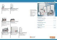
CARATTERISTICHE<br />
– Avviamento ed arresto graduale di motori<br />
trifase a gabbia di scoiattolo.<br />
– Relé di by-pass incorporato per<br />
l’esclusione completa dei semiconduttori.<br />
– Tensione nominale massima:<br />
400VAC 50/60Hz (ADXM...BP)<br />
220VAC 50/60Hz (ADXM...BP A220)<br />
480VAC 50/60Hz (ADXM...BP A480)<br />
600VAC 50/60Hz (ADXM...BP A600).<br />
– Corrente nominale: 6A, 12A e 18A.<br />
– Ingresso di comando avviamento/arresto:<br />
24...110VAC/DC<br />
110...480VAC.<br />
– Controllo accelerazione/decelerazione a<br />
rampa di tensione su 2 fasi.<br />
– Impostazione del tempo di accelerazione:<br />
0,5...10 secondi.<br />
– Impostazione del tempo di decelerazione:<br />
0,5...20 secondi.<br />
– Impostazione della coppia iniziale :<br />
0...85%.<br />
– 4 LED di indicazione stato.<br />
– Montaggio su guida omega 35mm.<br />
I AVVIATORI STATICI A SEMICONDUTTORE PER MOTORE TRIFASE<br />
CON AVVIAMENTO E ARRESTO GRADUALE<br />
GB SOFT STARTERS FOR THREE-PHASE MOTORS WITH<br />
SEMICONDUCTOR FOR SOFT START AND STOP<br />
E ARRANCADOR ESTATICO A SEMICONDUCTORES PARA MOTORES<br />
TRIFÁSICOS PARA ARRANQUE Y PARO SUAVE<br />
<strong>ADXM06BP</strong>... - <strong>ADXM12BP</strong>... - ADXM18BP...<br />
WARNING!<br />
– This equipment must be installed by<br />
qualified personnel, complying with<br />
current standards, to avoid damages or<br />
safety hazards. Products illustrated herein<br />
are subject to alterations and changes<br />
without prior notice. Technical data and<br />
descriptions in the documentation are<br />
accurate to the best of our knowledge,<br />
but no liabilities for errors, omissions, or<br />
contingencies arising therefrom are<br />
accepted.<br />
– A load-break switch or circuit breaker<br />
must be included in the electrical<br />
installation. It must be installed close by<br />
the equipment and within easy reach of<br />
the operator. It must be marked as the<br />
disconnecting device for the equipment:<br />
IEC/EN 61010-1 § 6.11.2.1.<br />
– Disconnect the power supply before<br />
making any installation or modifications<br />
on the circuit.<br />
– The by-pass relays in the main circuit<br />
may be in an undefined switching state<br />
due to handling during shipping. It is<br />
recommended to make the first cycle with<br />
the motor disconnected, to reset the<br />
by-pass relays.<br />
If not performed, this may cause<br />
unexpected motor operation.<br />
– The ADMX...BP starter is designed as<br />
Class A equipment. Use of the product in<br />
domestic environments can cause<br />
disturbances.<br />
– It is important to use the product<br />
according to its specified over voltage<br />
category.<br />
– At high ambient temperatures, it is<br />
essential to allow sufficient cooling time<br />
between starts.<br />
– For stand-alone units or with proper<br />
spacing between devices, the maximum<br />
ambient temperature can be +60°C.<br />
FEATURES<br />
– Gradual starting and stopping of<br />
induction (squirrel-cage) motors<br />
– Integrated by-pass relay to completely<br />
exclude semiconductors<br />
– Maximum rated voltage:<br />
400VAC 50/60Hz (ADXM...BP)<br />
220VAC 50/60Hz (ADXM...BP A220)<br />
480VAC 50/60Hz (ADXM...BP A480)<br />
600VAC 50/60Hz (ADXM...BP A600)<br />
– Rated current: 6A, 12A, 18A<br />
– Start/stop control input:<br />
24...110VAC/DC<br />
110...480VAC.<br />
– 2-phase acceleration/deceleration ramp<br />
voltage control<br />
– Acceleration ramp up time adjustment:<br />
0.5...10 seconds<br />
– Deceleration ramp down time adjustment:<br />
0.5...20 seconds<br />
– Initial torque adjustment: 0...85%<br />
– 4 LED status indicators<br />
– Mounting on 35mm DIN rail.<br />
ATENCIÓN!<br />
– Este equipo debe ser instalado por<br />
personal cualificado, cumpliendo con las<br />
normas vigentes, para prevenir daños a<br />
personas o cosas. Los productos<br />
descritos en este documento son<br />
susceptibles en cualquier momento de<br />
evoluciones o modificaciones.<br />
Las descripciones y los datos de catalogo<br />
no tienen valor contractual.<br />
– Un interruptor o disyuntor debe estar<br />
incluido en la instalación eléctrica.<br />
Este dispositivo debe instalarse<br />
próximo al ADXM...BP, y al alcance del<br />
operador. Debe marcarse como el<br />
dispositivo de interrupción del aparato:<br />
IEC/EN 61010-1 § 6.11.2.1.<br />
– Desconectar la alimentación de entrada<br />
antes de realizar la instalación, o<br />
modificaciones en el circuito.<br />
– El relé de by-pass en el circuito principal<br />
puede estar en un estado de conmutación<br />
indefinido debido al transporte.<br />
Se recomienda realizar el primer ciclo con<br />
el motor desconectado para lograr el<br />
reset del los contactos del relé de<br />
by-pass.<br />
De otra forma el motor puede<br />
experimentar una arranque indeseado.<br />
– El arrancador ADXM...BP está diseñado<br />
como equipo clase A. La utilización del<br />
equipo en ambiente domestico puede<br />
causar disturbios.<br />
– Es importante utilizar el producto según<br />
sus especificaciones de categoría de<br />
sobrevoltaje.<br />
– En ambiente de alta temperatura es<br />
necesario permitir suficiente tiempo de<br />
enfriamiento entre arranques sucesivos.<br />
– Cuando se instala un aparato solo, o<br />
cuando se permite especio entre aparatos<br />
contiguos, la temperatura ambiente puede<br />
alcanzar los 60ºC.<br />
CARACTERÍSTICAS<br />
– Arranque y paro gradual de motores de<br />
inducción (jaula de ardilla).<br />
– Relé de by-pass incorporado para la<br />
exclusión completa de los<br />
semiconductores.<br />
– Tensión nominal máxima:<br />
400VAC 50/60Hz (ADXM...BP)<br />
220VAC 50/60Hz (ADXM...BP A220)<br />
480VAC 50/60Hz (ADXM...BP A480)<br />
600VAC 50/60Hz (ADXM...BP A600).<br />
– Corriente nominal: 6, 12 y 18 amperios<br />
– Entrada de comando arranque/paro:<br />
24...110VAC/DC<br />
110...480VAC<br />
– Control de aceleración/ desaceleración a<br />
rampa de tensión en 2 fases.<br />
– Tiempo de ajuste de la rampa de<br />
aceleración: 0,5...10 segundos.<br />
– Tiempo de ajuste de la rampa de<br />
desaceleración: 0,5...20 segundos.<br />
– Ajuste del par inicial: 0...85%.<br />
– 4 LEDs indicadores de estatus.<br />
– Montaje en guía DIN 35mm.<br />
1
I070 I GB E 05 09<br />
2<br />
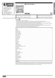
DESCRIZIONE<br />
Avviatore statico per motori in AC compatto<br />
e facile da utilizzare. Con questa unità<br />
possono essere avviati e rallentati<br />
gradualmente motori trifase aventi corrente<br />
nominale di 6A, 12A e 18A, in base alla<br />
taglia. I tempi di avviamento, di arresto e di<br />
coppia iniziale possono essere regolati<br />
indipendentemente mediante i potenziometri<br />
presenti sul fronte.<br />
IMPOSTAZIONE<br />
Funzione Range<br />
Accelerazione 0,5...10s<br />
RAMP UP<br />
Accelerazione 0,5...20s<br />
RAMP DOWN<br />
Coppia iniziale 0...85% Ue<br />
INIT. TORQUE<br />
FUNZIONAMENTO<br />
Regolazione tempo di accelerazione<br />
RAMP UP<br />
Espressa in secondi determina il tempo che<br />
intercorre fra lo start del motore ed il<br />
raggiungimento della piena tensione.<br />
Regolare il tempo di RAMP UP in modo che<br />
il relè di by-pass chiuda quando la corrrente<br />
è prossima alla nominale del motore.<br />
Regolazione tempo di decelerazione<br />
RAMP DOWN<br />
Espressa in secondi determina la rampa di<br />
decelerazione del motore. Permette di<br />
prolungare il tempo di arresto del motore<br />
riducendo gradualmente la tensione.<br />
Il tempo effettivo di arresto del motore può<br />
variare in base alle caratteristiche del carico.<br />
Impostazione del valore di coppia iniziale<br />
Tensione erogata dall’avviatore nei primi<br />
istanti dell’accelerazione, dopo di che<br />
crescerà linearmente sino al suo valore<br />
massimo con una pendenza determinata<br />
dalla regolazione RAMP UP.<br />
DESCRIPTION<br />
Compact easy-to-use AC semiconductor<br />
motor controller. Three-phase motors with<br />
rated current of 6A, 12A and 18A depending<br />
on the size, can be soft-started and/or softstopped<br />
with this starter. Starting and<br />
stopping time as well as initial torque can be<br />
independently adjusted by built-in<br />
potentiometers.<br />
SETTING<br />
Function Range<br />
RAMP UP 0.5...10s<br />
RAMP DOWN 0.5...20s<br />
Initial torque 0...85% Ue<br />
INIT. TORQUE<br />
OPERATION<br />
Acceleration RAMP UP time adjustment<br />
Timing, in seconds, determines the interval<br />
between the motor starting and full voltage<br />
activation.<br />
Adjust the RAMP UP time in such a way so<br />
the by-pass relay closes when the current is<br />
about to reach the rated motor current value.<br />
Deceleration RAMP DOWN time adjustment<br />
Timing, in seconds, determines the motor<br />
deceleration ramp and consents to prolong<br />
the motor stopping time by gradually<br />
reducing the voltage. The actual motor<br />
stopping time can vary depending on the<br />
load characteristics.<br />
Initial torque value programming<br />
This determines the voltage delivered by the<br />
starter at the very instant of acceleration,<br />
then it linearly increases up to the maximum<br />
value with a trend established by the<br />
RAMP UP adjustment.<br />
DESCRIPCIÓN<br />
Arrancador estático compacto fácil de usar<br />
para motor AC. Con este arrancador puede<br />
realizarse tanto el arranque suave como el<br />
paro suave de motores trifásicos de 6, 12 o<br />
18 amperios según el calibre. El tiempo de<br />
arranque y paro así como el par inicial<br />
pueden ajustarse de manera independiente<br />
mediante potenciómetros integrados en el<br />
frontal.<br />
AJUSTE<br />
Función Rango<br />
Rampa de aceleración 0,5...10s<br />
RAMP UP<br />
Rampa de desaceleración 0,5...20s<br />
RAMP DOWN<br />
Par inicial 0...85% Ue<br />
INIT. TORQUE<br />
VISUALIZZAZIONE LED LED INDICATORS LEDS VISUALIZACION<br />
FUNZIONE FUNCTIONS FUNCION LED COLORE / COLOUR STATO / STATUS / ESTATUS<br />
Alimentazione Power on Alimentación POWER ON verde / green / verde fisso / constantly on / fijo<br />
Rampa Ramping Rampa RAMPING giallo / yellow / amarillo fisso / constantly on / fijo<br />
Relè di by-pass By-pass connected Relé de by-pass BY-PASS giallo / yellow / amarillo fisso / constantly on / fijo<br />
inserito conectado<br />
OPERACIÓN<br />
Ajuste de la rampa de aceleración<br />
RAMP UP<br />
Expresada en segundos determina el tiempo<br />
entre la orden de arranque de motor y la<br />
conexión a tensión plena de línea.<br />
Ajustar el tiempo de RAMP UP de manera<br />
que el relé de by-pass se cierra cuando la<br />
corriente es próxima a la corriente nominal<br />
del motor.<br />
Ajuste de la rampa de desaceleración<br />
RAMP DOWN<br />
Expresada en segundos determina la rampa<br />
de desaceleración del motor. Permite<br />
prolongar el tiempo de paro del motor<br />
reduciendo gradualmente la tensión.<br />
El tiempo efectivo de paro del motor puede<br />
variar en base a las características de la<br />
carga.<br />
Ajuste del valor del par inicial<br />
Determina la tensión aplicada por el<br />
arrancador al motor en el instante inicial del<br />
arranque, luego se incrementa linealmente<br />
hasta el valor máximo con una tendencia<br />
establecida por la regulación RAMP UP.
I070 I GB E 05 09<br />
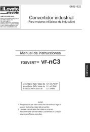
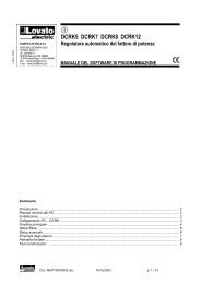
DIAGRAMMA DI FUNZIONAMENTO OPERATIONAL DIAGRAMS DIAGRAMAS DE FUNCIONAMIENTO<br />
Diagramma 1: Funzionamento normale Diagram 1: Normal Operation Diagrama 1: Operación normal<br />
Mains L1, L2, L3<br />
Uc control input<br />
Motor Supply T1, T2, T3<br />
POWER ON LED<br />
BY-PASS ON LED<br />
RAMPING LED<br />
PROGRAMMAZIONE POTENZIOMETRI PROGRAMMING OF POTENTIOMETERS AJUSTE DE LOS POTENCIOMETROS<br />
➀ Rampa di accelerazione: 0,5...10s. Tempo in cui<br />
la tensione sul motore passa dal valore di<br />
coppia iniziale impostato a Ue.<br />
➁ Rampa di decelerazione: 0,5...20s. Tempo in cui<br />
la tensione sul motore passa da Ue a 0.<br />
➂ Coppia iniziale: 0...85%. Percentuale della<br />
tensione Ue erogata istantaneamente al motore<br />
al momento dell’avviamento.<br />
NOTE<br />
1. I cicli di avviamento/arresto non devono<br />
avere tempi inferiori a 3 secondi ON e 3<br />
secondi OFF. In presenza di cicli di<br />
avviamento/arresto più veloci non è<br />
garantito che l’uscita dell’avviatore segua<br />
lo stato del segnale di comando.<br />
IMPORTANTE!<br />
Se il dispositivo viene utilizzato per<br />
avviamenti ciclici, tenere in<br />
considerazione in numero massimo di<br />
avviamenti/ora ed i valori di sovraccarico<br />
termico del motore.<br />
2. Una mancanza fase di L1 oppure L2<br />
causa il ripristino dell’avviatore in quanto<br />
questi fasi forniscono l’alimentazione<br />
interna.<br />
3. Ripetitivi abbassamenti delle tensioni di<br />
fase durante il normale funzionamento<br />
possono causare il surriscaldamento del<br />
motore. Nel caso di motore avviato e con<br />
relè di by-pass chiuso, abbassamenti di<br />
tensione su L1 o L2 possono causare<br />
l’apertura del relè di by-pass.<br />
Per resettare l’apparecchio e procedere<br />
ad un nuovo avviamento è indispensabile<br />
disalimentare l’avviatore.<br />
1<br />
2<br />
3<br />
➀ Acceleration ramp: 0.5...10s range. Time interval<br />
during which the voltage flow to the motor begins<br />
at the regulated initial torque value and increases<br />
to Ue load conditions.<br />
➁ Deceleration ramp: 0.5...20s range. Time interval<br />
during which the voltage flow to the motor starts<br />
at Ue and decreases to zero load voltage.<br />
➂ Initial torque: 0...85% range. Percentage of the<br />
rated voltage Ue instantaneously delivered to the<br />
motor at the moment of starting.<br />
NOTES:<br />
1. Start-stop cycling must never be faster<br />
than 3 seconds ON and 3 seconds OFF.<br />
At faster rate times, it cannot be<br />
warranted the starter output responds to<br />
the given control input.<br />
IMPORTANT!<br />
If the unit is used for cycles, the<br />
maximum number of starts per hour and<br />
the motor thermal overload values must<br />
be taken into account.<br />
2. A phase loss on L1 or L2 causes the<br />
starter to reset as these phases provide<br />
the internal power supply.<br />
3. Repeated phase voltage dips during<br />
normal running may lead to motor<br />
overheating. In case the motor is started<br />
and the by-pass relay is closed, voltage<br />
lowering on L1 or L2 can cause the<br />
by-pass relay to reopen. To reset the unit<br />
and begin a new start, power must be<br />
removed from the unit.<br />
➀ Rampa de aceleración: 0.5...10s. Tiempo durante<br />
el cual la tensión aplicada al motor pasa del valor<br />
de par inicial a plena tensión de línea Ue.<br />
➁ Rampa de desaceleración: 0,5...20s. Tiempo<br />
durante el cual la tensión aplicada al motor<br />
disminuye desde UE hasta cero.<br />
➂ Par inicial: 0...85% Porcentaje de la inicial de la<br />
tensión Ue instantáneamente aplicado al<br />
motor en el momento inicial del arranque.<br />
NOTAS:<br />
1. En el ciclo de arranque-parada los<br />
tiempos ON y OFF no deben ser<br />
inferiores a 3 segundos. A tiempos<br />
inferiores no se garantiza que la<br />
respuesta de salida del arrancador<br />
responda a la señal de control dada.<br />
IMPORTANTE!<br />
Si el ADXM...BP se utiliza para arranque<br />
cíclico el respetar el máximo numero de<br />
arranques por hora y el estado de<br />
sobrecarga térmica del motor.<br />
2. El fallo de las fases L1 o L2 causa el<br />
reinicio del arrancador, debido a que<br />
estas dos fases suministran la tensión<br />
auxiliar interna.<br />
3. Caídas de tensión repetidas durante<br />
operación normal pueden causar<br />
sobrecalentamiento del motor. Caídas de<br />
tensión en las fases L1 y L2 pueden<br />
causar la apertura del relé de by-pass.<br />
Para reiniciar el aparato y comenzar un<br />
nuevo arranque, se debe retirar la<br />
alimentación.<br />
3
I070 I GB E 05 09<br />
4<br />
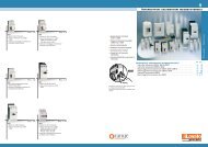
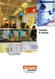
SCHEMA DI COLLEGAMENTO WIRING DIAGRAM ESQUEMA ELÉCTRICO<br />
L’avviatore effettua il by-pass dei<br />
semiconduttori durante la marcia. Pertanto i<br />
semiconduttori possono essere<br />
danneggiati esclusivamente da correnti di<br />
cortocircuito durante la rampa di avviamento<br />
oppure di decelerazione. L’avviatore non<br />
isola il motore dalla rete.<br />
Figura 1 - Utilizzo dei fusibili<br />
I fusibili per semiconduttori proteggono la<br />
linea di alimentazione del motore e l’avviatore<br />
stesso contro danni da cortocircuito.<br />
Figura 2 - Utilizzo di interruttore<br />
magnetotermico<br />
Utilizzando un relè magnetotermico si ottiene<br />
la protezione della linea e del motore ma non<br />
si ha la certezza di proteggere il soft start.<br />
In caso di guasto nel motore, se la resistenza<br />
degli avvolgimenti limita la corrente di<br />
guasto, il magnetotermico può anche<br />
proteggere il soft start, ma sicuramente non<br />
in caso di correnti di cortocircuito.<br />
Figura 3 - Utilizzo dei comandi ausiliari<br />
3.1 Avviamento mediante comando a 2 fili.<br />
Quando K è chiuso e l’ingresso di comando<br />
A1-A2 (o A3) è alimentato si attiva<br />
l’avviamento graduale del motore. Quando K<br />
si apre si attiva la decelerazione graduale.<br />
Figura 4 - Utilizzo dei pulsanti marciaarresto<br />
Premendo S1 l’avviatore inizia la rampa di<br />
accelerazione. Premendo S2 inizia la rampa<br />
di decelerazione. K è un contatto di un relè<br />
ausiliario.<br />
Figura 5 - Comando a 2 fasi<br />
Collegando due fasi all’ingresso A1-A2<br />
(o A3), l’avviatore inizia la rampa di<br />
accelerazione del motore dopo che K è<br />
chiuso.<br />
All’apertura di K, il motore si ferma senza la<br />
rampa di discesa.<br />
The starter by-passes the semiconductors<br />
during its running. Therefore, the<br />
semiconductors can only be damaged by<br />
short-circuit currents during ramp-up and<br />
ramp-down.<br />
The starter does not isolate the motor from<br />
mains.<br />
Figure 1 - Use of fuses<br />
Semiconductor fuses protect the motor<br />
supply line and starter from damage due to<br />
short circuit conditions.<br />
Figure 2 - Use of motor protection circuit<br />
breakers<br />
The use of a circuit breaker, with magnetic<br />
and thermal trip releases, as protection<br />
device can warrant protection to the motor<br />
feeding line only but none for the starter<br />
operation.<br />
When motor failure occurs, if part of the<br />
motor winding limits the fault current and<br />
the motor feeding line is protected, this type<br />
of protection can be considered acceptable.<br />
Figure 3 - Use of auxiliary devices<br />
3.1 Two-wire starting control.<br />
When K is closed, the control input is<br />
supplied to A1-A2 (or A3) and soft starting<br />
of the motor is performed.<br />
When K is opened, soft stopping is conducted.<br />
Figure 4 - Use of ON and OFF push buttons<br />
Pressing S1, soft starting begins.<br />
Pressing S2, soft stopping is activated.<br />
K is an auxiliary contact of an auxiliary relay.<br />
Figure 5 - 2-phase control<br />
By connecting two of the incoming phases to<br />
A1-A2 (or A3), soft starting is activated when<br />
K is closed.<br />
When K is opened, the motor is stopped<br />
without ramp down.<br />
A1<br />
A1-A2: 24...110VAC/DC ±15%<br />
A1-A3: 110...480VAC ±15%<br />
Fig. 1 Fig. 2 Fig. 3<br />
A2<br />
A3<br />
Fig. 4<br />
El arrancador efectúa el by-pass de los<br />
semiconductores durante la marcha. Por<br />
esta razón los semiconductores solamente<br />
pueden dañarse debido a corto-circuitos<br />
durante las rampas de aceleración o<br />
desaceleración.<br />
El arrancador no aísla el motor de la red.<br />
Figura 1. Protección mediante fusibles<br />
La utilización de fusibles para<br />
semiconductores permite la protección del<br />
arrancador, del motor y del alimentador del<br />
daño debido a posibles corto-circuitos.<br />
Figura 2. Protección mediante<br />
interruptores magneto-térmicos<br />
La utilización de un interruptor magnetotérmico<br />
como dispositivo de protección<br />
garantiza la protección del alimentador, pero<br />
no garantiza la funcionalidad del arrancador.<br />
En caso de fallo del motor, si parte de los<br />
devanados del motor limitan la corriente de<br />
fallo, y el alimentador está protegido, este<br />
tipo de protección se considera aceptable.<br />
Figura 3. Conexiones auxiliares<br />
3.1 Control utilizando un interruptor de 2<br />
posiciones:<br />
Cuando K esta en posición cerrado, la tensión<br />
de alimentación de control se suministra a los<br />
terminales A1, A2 (o A3) y el aranque suave<br />
del motor se realiza.<br />
Figura 4. Control utilizando pulsadores ON y<br />
OFF<br />
Pulsando S1, el arranque suave se inicia.<br />
Pulsando S2, el paro suave se inicia<br />
K es un contacto de un contactor auxiliar.<br />
Figura 5. Control utilizando 2 fases<br />
Conectando los terminales A1, A2 (o A3) a<br />
dos fases de la entrada de alimentación de<br />
potencia, el arranque suave comienza cuando<br />
el contactor K se cierra.<br />
Cuando el contactor K se abre, el paro del<br />
motor se realiza sin rampa de desaceleración.<br />
A1<br />
A2<br />
A3<br />
A1-A2: 24...110VAC/DC ±15%<br />
A1-A3: 110...480VAC ±15%<br />
Fig. 5
I070 I GB E 05 09<br />
COMPONENTI SUGGERITI PER IL<br />
COORDINAMENO DELLA PROTEZIONE<br />
CONTRO IL CORTO CIRCUITO.<br />
❶ COORDINAMENTO TIPO 2<br />
Valore della corrente di cortocircuito: 10kA quando è<br />
protetto con fusibile a semiconduttore.<br />
ADVISABLE COMPONENTS FOR THE<br />
COORDINATION OF SHORT-CIRCUIT<br />
PROTECTION<br />
COMPONENTES SUGERIDOS PARA<br />
LOGRAR COORDINACIÓN DE<br />
PROTECCIONES CONTRA CORTO-CIRCUITO<br />
<strong>ADXM06BP</strong>... <strong>ADXM12BP</strong>... ADXM18BP...<br />
Fusibili per semiconduttori ❶ (IEC/EN 60947-4-2) Ferraz Shawmut Ferraz Shawmut Ferraz Shawmut<br />
Semiconductors fuses ❶ (IEC/EN 60947-4-2) 25A, Class URC. 40A, Class URC. 40A, Class URC.<br />
Fusibles ❶ (IEC/EN 60947-4-2) Art. N° 6.9 CP Art. N° 6.9 CP Art. N° 6.9 CP<br />
gRC 14.51 25 gRC 14.51 40 gRC 14.51 40<br />
Interruttore magnetotermico<br />
Motor protection circuit breaker<br />
Guardamotor magneto-térmico<br />
SM1B 32 SM1B 40 SM1B 44<br />
Nota per applicazione UL (UL508) Adatto per operare in un Adatto per operare in un Adatto per operare in un<br />
Note for UL duty (UL508) circuito capace di erogare circuito capace di erogare circuito capace di erogare<br />
Nota para aplicación UL (UL 508) non più di 5kA (10kA per non più di 10kA RMS non più di 10kA RMS<br />
<strong>ADXM06BP</strong> A600) RMS simmetrici - 600V massimo simmetrici - 600V massimo<br />
simmetrici - 600V massimo quando protetto con fusibili quando protetto con fusibili<br />
quando protetto con fusibili Classe RK5 con corrente Classe RK5 con corrente<br />
Classe RK5 con corrente<br />
massima 12A<br />
massima 30A massima 35A<br />
Suitable for use on a circuit Suitable for use on a circuit Suitable for use on a circuit<br />
capable of delivering not capable of delivering not capable of delivering not<br />
more than 5KA (10kA for more than 10KA RMS more than 10KA RMS<br />
<strong>ADXM06BP</strong> A600) RMS symmetrical amperes, symmetrical amperes,<br />
symmetrical amperes, 600V maximum when 600V maximum when<br />
600V maximum when protected by RK5 class protected by RK5 class<br />
protected by RK5 class<br />
fuses rated max. 12A<br />
fuses rated max. 30A fuses rated max. 35A<br />
Especificados para uso en Especificados para uso en Especificados para uso en<br />
circuito capaz de disipar no circuito capaz de disipar no circuito capaz de disipar no<br />
mas de 5kA (10kA para mas de 10kA RMS simétricos, mas de 10kA RMS simétricos,<br />
ADXM06P A600) RMS 600V máximo, cuando se 600V máximo, cuando se<br />
simétricos, 600V máximo, protege con fusibles tipo RK5 protege con fusibles tipo RK5<br />
cuando se protege con con corriente nominal con corriente nominal<br />
fusibles tipo RK5 con<br />
corriente nominal máxima 12A<br />
máxima 30A máxima 35A<br />
❶ TYPE OF COORDINATION: 2<br />
Rated short circuit current: 10kA when protected by<br />
semiconductor fuses.<br />
❶ TIPO DE COORDINACIÓN: 2<br />
Intensidad de cortocircuito nominal: 10kA si hay<br />
protección con fusibles semiconductores.<br />
CARATTERISTICHE SCR<br />
<strong>ADXM06BP</strong> / <strong>ADXM12BP</strong> / ADXM18BP /<br />
<strong>ADXM06BP</strong> A220 / <strong>ADXM12BP</strong> A220 / ADXM18BP A220 /<br />
<strong>ADXM06BP</strong> A480 <strong>ADXM12BP</strong> A480 ADXM18BP A480<br />
I2t 525A2s 525A2s 1800A2 SCR CHARACTERISTICS<br />
CARACTERISICAS SCR<br />
s<br />
Itsm 325A 325A 600A<br />
<strong>ADXM06BP</strong> A600 <strong>ADXM12BP</strong> A600 ADXM18BP A600<br />
I2t 1920A2s 1920A2s 1920A2s Itsm 620A 620A 620A<br />
NUMERO MASSIMO DI AVVIAMENTI/ORA MAXIMUM NUMBER OF STARTING/HOUR NÚMERO MÁXIMO DE ARRANQUES/HORA<br />
Temperatura di impiego 40°C Temperatura di impiego 50°C Temperatura di impiego 60°C<br />
Operating temperature 40°C Operating temperature 50°C Operating temperature 60°C<br />
Temperatura de operacion 40°C Temperatura de operacion 50°C Temperatura de operacion 60°C<br />
Cicli di sovraccarico Avv./ora Cicli di sovraccarico Avv./ora Cicli di sovraccarico Avv./ora<br />
Overload cycle Start/hour Overload cycle Start/hour Overload cycle Start/hour<br />
Ciclo de sobrecarga Arranques/Hora Ciclo de sobrecarga Arranques/Hora Ciclo de sobrecarga Arranques/Hora<br />
<strong>ADXM06BP</strong>... 6A: AC-53b: 4-5: 4 250 6A: AC-53b: 4-5: 26 100 6A: AC-53b: 4-5: 62 50<br />
<strong>ADXM12BP</strong>... 12A: AC-53b: 4-5: 50 60 12A: AC-53b: 4-5: 62 50 12A: AC-53b: 4-5: 80 40<br />
ADXM18BP... 18A: AC-53b: 4-5: 50 60 18A: AC-53b: 4-5: 62 50 18A: AC-53b: 4-5: 110 30<br />
DIMENSIONI [mm] DIMENSIONS [mm] DIMENSIONES [mm]<br />
45<br />
114<br />
110<br />
126<br />
117<br />
83<br />
5
I070 I GB E 05 09<br />
CARATTERISTICHE TECNICHE TECHNICAL CHARACTERISTICS CARACTERISTICAS TECNICAS<br />
CIRCUITO DI ALIMENTAZIONE E CONTROLLO <strong>ADXM06BP</strong>... <strong>ADXM12BP</strong>... ADXM18BP...<br />
Tensione alimentazione motore Ue ADXM...BP: 400VAC -15% +10%<br />
ADXM...BP A220: 220VAC❶ -15% +10%<br />
ADXM...BP A480: 480VAC❶ -15% +10%<br />
ADXM...BP A600: 600VAC❶ -15% +10%<br />
Tensione di ingresso comando Uc A1-A2: 24...110VAC/DC ±15%; A1-A3:110...480VAC ±15%<br />
Corrente di ingresso comando max: 5mA - min: 1mA<br />
Frequenza di rete 50/60Hz ±10%<br />
Fasi controllate 2<br />
Metodo di avviamento/arresto Rampa di tensione / Voltage ramp / Rampa de tensión<br />
Categoria di utilizzo AC-53b<br />
Corrente nominale motore In a 40°C (IEC) 6A 12A 18A<br />
Corrente minima di funzionamento 250mA 250mA 250mA<br />
Potenza del motore a 60°C secondo IEC 2.2kW (<strong>ADXM06BP</strong>) 5.5kW (<strong>ADXM12BP</strong>) 7.5kW (ADXM18BP)<br />
1.1kW (<strong>ADXM06BP</strong> A220) 3.0kW (<strong>ADXM12BP</strong> A220) 4.0kW (ADXM18BP A220)<br />
2.2kW (<strong>ADXM06BP</strong> A480) 5.5kW (<strong>ADXM12BP</strong> A480) 7.5kW (ADXM18BP A480)<br />
3.0kW (<strong>ADXM06BP</strong> A600) 7.5kW (<strong>ADXM12BP</strong> A600) 11kW (ADXM18BP A600)<br />
Potenza del motore a 60°C secondo UL 3.0HP (<strong>ADXM06BP</strong>) 7.5HP (<strong>ADXM12BP</strong>) 10HP (ADXM18BP)<br />
1.5HP (<strong>ADXM06BP</strong> A220) 3.0HP (<strong>ADXM12BP</strong> A220) 5.0HP (ADXM18BP A220)<br />
5.0HP (<strong>ADXM06BP</strong> A480) 7.5HP (<strong>ADXM12BP</strong> A480) 10HP (ADXM18BP A480)<br />
5.0HP (<strong>ADXM06BP</strong> A600) 10HP (<strong>ADXM12BP</strong> A600) 15HP (ADXM18BP A600)<br />
Numero di cicli di sovraccarico (IEC/EN 60947-4-2) a 40°C 6A: AC-53b: 4-5: 4 12A: AC-53b: 4-5: 50 18A: AC-53b: 4-5: 50<br />
Numero di avviamenti ora a 40°C 250 60 60<br />
Relè di by-pass Sì / Yes<br />
Potenza dissipata con by-pass chiuso 20W 20W 20W<br />
CARATTERISTICHE DI AVVIAMENTO<br />
Rampa accelerazione 0.5...10s<br />
Rampa di decelerazione 0.5...20s<br />
Coppia iniziale 0...85%<br />
CONDIZIONI AMBIENTALI<br />
Temperatura di impiego -20...+60°C<br />
Temperatura di stoccaggio -50...+85°C<br />
Umidità relativa