BLU 3000.1 PR / MD BLU 4000.1 PR / MD - Elco Ecoflam
BLU 3000.1 PR / MD BLU 4000.1 PR / MD - Elco Ecoflam
BLU 3000.1 PR / MD BLU 4000.1 PR / MD - Elco Ecoflam
- No tags were found...

Create successful ePaper yourself
Turn your PDF publications into a flip-book with our unique Google optimized e-Paper software.
LB 382 <strong>BLU</strong> <strong>3000.1</strong> - <strong>4000.1</strong> <strong>PR</strong>/<strong>MD</strong>AALLACCIAMENTO ALLA LINEA GASAllacciato il bruciatore alla tubazione del gas è necessario assicurarsi che quest’ultima sia a tenuta perfetta. Assicurarsi pure che ilcamino non sia ostruito. Aperto il rubinetto del gas sfiatare con prudenza la tubazione attraverso l’apposita presa di pressione equindi controllare il valore della pressione con un manometro idoneo. Dare tensione all’impianto e regolare i termostati alla temperaturadesiderata. Alla chiusura dei termostati, il dispositivo di controllo fughe gas effettua una prova di tenuta delle valvole; Al terminedella prova il bruciatore riceve il consenso per effettuare il ciclo di avviamento.ALLACCIAMENTO ELETTRICOTutti i bruciatori sono collaudati a 400 V 50 Hz trifase per i motori e 230V 50 Hz monofase con neutro per gli ausiliari.Se fosse necessario alimentare il bruciatore a 230 V 50 Hz trifase senza neutro, eseguire le modifiche necessarie riferendosi allo specificoschema elettrico del bruciatore e controllare che il relé termico sia entro il campo di assorbimento del motore.Accertare inoltre il corretto senso di rotazione del motore del ventilatore.AVVIAMENTO DEL BRUCIATOREPrima di accendere il bruciatore, assicurarsi che sia montato correttamente. Controllare i collegamenti elettrici secondo i diagrammie le tubazioni dell’impianto. Prima del collegamento elettrico assicurarsi che il voltaggio corrisponda ai dati indicati nella targhettacaratteristiche.Il diagramma del collegamento elettrico e il ciclo di avviamento sono illustrati separatamente. Per collegare l’apparecchiaturaal bruciatore, vedere lo schema. Prestare particolarmente attenzione al collegamento del neutro e della fase: non scambiarlimai. Controllare il collegamento terra dell’impianto. Nei motori trifase controllare il senso di rotazione del motore (vedere freccia).Sfiatare l’aria e le impurità della tubazione del gas. Controllare che la pressione del gas sia nei limiti indicati nella targhetta. Questocontrollo deve essere effettuato con un manometro gas nell’apposita presa di pressione prevista sul bruciatore. Si avvia il motore edinizia la preventilazione. Il motoriduttore porta la serranda dell’aria alla massima apertura in circa 30 secondi. Quando il motoriduttoreé completamente aperto, un segnale all’apparecchiatura elettronica di controllo avvia un ciclo di preventilazione di circa 66secondi. Alla fine di questa preventilazione, il motoriduttore porta la serranda in bassa fiamma permettendo l’accensione del bruciatorealla minima portata. Contemporaneamente il trasformatore di accensione viene alimentato e dopo tre secondi (pre-accensione)vengono alimentate le valvole del gas. A questo punto la valvola a farfalla regola la portata del gas nella testa di combustione. Duesecondi dopo l’apertura delle valvole, il trasformatore é escluso dal circuito. In caso di mancanza di accensione il bruciatore va inblocco entro due secondi. Il bruciatore si trova acceso alla minima potenza (circa 30% della massima potenza). Lo strumentomodulatore farà aprire il servomotore alla massima potenza o lo fermerà alla potenza intermedia richiesta dall’impianto. L’aperturadel servomotore farà aprire gas ed aria in modo proporzionale per avere sempre a tutte le portate (30%-100%) una combustioneottimale. Al termine del funzionamento il servomotore si porta in posizione di chiusura.REGOLAZIONE DELLA COMBUSTIONEATTENZIONE : per ottenere una corretta regolazione della combustione e della portata termica occorre effettuare l'analisi dei fumi, servendosidegli appositi strumenti. La regolazione della combustione e della portata termica va eseguita contemporaneamente ad una analisidei prodotti della combustione, assicurandosi che i valori riscontrati siano corretti, e, in ogni caso, rispondenti alle normative di sicurezzavigenti. A tal proposito vedere la tabella e la figura sottostanti.TALE OPERAZIONE DEVE ESSERE ESEGUITA DA PERSONALE <strong>PR</strong>OFESSIONALMENTE QUALIFICATO ED AUTO-RIZZATO DALLA ECOFLAM SPA .VALORI DI RIFERIMENTO CONSIGLIATIMetanoCO2 9,6%CO
ALB 382 <strong>BLU</strong> <strong>3000.1</strong> - <strong>4000.1</strong> <strong>PR</strong>/<strong>MD</strong>CICLO DI FUNZIONAMENTO DELL’APPARECCHIATURA LANDIS & STAEFA MOD. LFL1.622Pressostato gasMotore ventilatorePressostato ariaTrasformatoredi accensioneValvola gasConsensomin./max. potenza100%Serranda aria min0Farfalla gasRivelazionedi fiammaSpia di bloccot1Ciclo di funzionamento normalet2t4t3t1Ciclo di funzionamentoin mancanza di fiamma all'accensionet2t4t3t5 t6Rif. descrizioneduratat1 tempo di attesa della conferma dellapressione dell'aria 8"t2 tempo di preventilazione 66"t3 tempo di sicurezza 2"t4 tempo di preaccensione 4"t5 tempo per il consenso di funzionam.alla minima potenza della valvola dilavoro del combustibile 10""t6 tempo per il consenso di funzionam.alla massima potenza della valvola dilavoro del combustibile 10"L’apparecchiatura controllo fiamma fa partire il ventilatore del bruciatore per effettuare il prelavaggio della camera di combustione,controllando la presione dell’aria di ventilazione tramite il pressostato aria. Al termine della preventilazione entra in funzione il trasformatoredi accensione generando una scintilla tra gli elettrodi e contemporaneamente si aprono le valvole del gas (valvole gas disicurezza VS e valvola di lavoro VL). La sicurezza totale in caso di mancata accensione o di spegnimento accidentale viene affidata auna sonda di rivelazione che interviene mandando in blocco l’apparecchiatura entro il tempo di sicurezza. Nel caso di mancanza digas o di un calo notevole di pressione il pressostato gas di minima provvede ad interrompere il funzionamento del bruciatore.SERVOCOMANDO ARIA LANDIS & STAEFA SQM 50.481A2Togliere il coperchio per accedere alle camme di regolazione. Lo spostamento delle camme va effettuato con l’ausiliodell’apposita chiavetta in dotazione. Descrizione :I - Camma di regolazione posizione di apertura in potenza max.II - Camma di regolazione della posizione serranda allo spegnimento.III - Camma di regolazione posizione di apertura in potenza min.Camma VIIInon usataIV - Camma di regolazione posizione di apertura in bassa fiamma.V - Camma non usataVI - Camma non usataVII - Camma non usataVIII- Camma non usatapag.4
+--LB 382 <strong>BLU</strong> <strong>3000.1</strong> - <strong>4000.1</strong> <strong>PR</strong>/<strong>MD</strong>AREGOLAZIONE DELLA PORTATA ARIA E GASCOMMUTATORE0AUTO-Part. 1+Part. 2Part. 30 = bloccaggio degli apparati per ilfunzionamento in una posizione intermadia= funzionamento alla massima potenza= funzionamento alla minima potenzaAUTO = funzionamento automaticoREGOLAZIONE DELLA POTENZA MINIMA DEL GASPosizionare il commutatore che si trova sulla mostrina in posizione 2 e agire come segue:Per regolare la portata minimo del gas agire con la chiave a brugola sulla vite della camma e modificare l’angolo dellaserranda gas della valvola a farfalla.REGOLAZIONE DELLA POTENZA MASSIMA DEL GASPosizionare il commutatore che si trova sulla mostrina in posizione 1 e agire come segue:Per regolare la portata massimo del gas agire sull’elettrovalvola di regolazione fino a ottenere il valore corretto per la caldaia.REGOLAZIONE DELLA PORTATA MASSIMA DELL’ARIASvitare la vite di fissaggio dell’asta e mettere la stessa nella posizione corretta.Alla fine della regolazione richiudere la vite dell’asta.REGOLAZIONE DELLA PORTATA INTERMEDIA DEL GASAzionare il servomotore con il commutatore (aperto/chiuso) e posizionarlo nella posizione 0 per fermarlo. Per la regolazione,agire come segue. Ripetere i passaggi per gli altri punti delle camme.Regolazione della portata intermediaria del gas (vedere immagine 3):Con una chiave a brugola modificare la posizione della lamina guida della camma, chiudendo la portata aumenta,aprendo la portata diminuisce.CALCOLO PORTATA BRUCIATOREPer calcolare la portata in kW del bruciatore, procedere nel modo seguente :Controllare al contatore la portata in litri del gas e il tempo in secondi della lettura.Procedere al calcolo secondo la formula : e x f = kWsecfe = Litri gassec = Tempo in secondiG20 = 34,02G25 = 29,25G30 = 116G31 = 88pag.5
5ALB 382 <strong>BLU</strong> <strong>3000.1</strong> - <strong>4000.1</strong> <strong>PR</strong>/<strong>MD</strong>REGOLAZIONE DELLA COMBUSTIONEATTENZIONE: Ai fini di una corretta regolazione della combustione e della portata termica, queste vanno eseguitecontemporaneamente ad una analisi dei fumi, da effettuarsi con strumenti appositi, controllamndo che i valori riscontratisiano corretti e rispondenti alle normative di sicurezza in vigore. Le operazioni di rgolazione debbono essere effettuateda personale qualificato ed autorizzato dalla <strong>Ecoflam</strong> S.p.A.REGOLAZIONE TESTA DI COMBUSTIONE-+POSIZIONE DEGLI ELETTRODIElettrodo di accensione7 mm4 mm7 mm""Elettrodo di rivelazioneTARATURA DEL <strong>PR</strong>ESSOSTATO GAS DI MINIMA <strong>PR</strong>ESSIONEpressostato gas- svitare le viti I e L e togliere il coperchio M- posizionare il regolatore N ad un valore pari al 60% della pressione nominale di alimentazione gas(es.: per gas metano press. nominale =20 mbar; regolatore posizionato al valore 12 mbar; perG.P.L. pressione nominale G30-G31 30/37 mbar regolatore posizionato al valore di 18 mbar) M- rimontare il coperchio M e riavvitare le viti I e LITARATURA DEL <strong>PR</strong>ESSOSTATO ARIA- svitare le viti A e B e togliere il coperchio CL- tarare il pressostato aria al minimo, ruotando il regolatore D in posizione 1.- avviare il bruciatore e impostare il funzionamento in 1° stadio (1 fiamma).pressostato aria- verificare la corretta combustione.- con l’ausilio di un cartoncino ostruire progressivamente il condotto di aspirazione dell’ariafino ad ottenere un aumento del valore di CO2 di circa 0,5÷0,8 %, oppure, se si dispone di Cun manometro collegato alla presa di pressione E, fino ad ottenere una diminuzione di 0,1mbar (~10 mm C.A.).A- aumentare lentamente il valore di taratura del pressostato, fino a causare lo spegnimento inblocco del bruciatore.B- togliere l’ostruzione al condotto di aspirazione aria e rimontare il coperchio C.- ripristinare il funzionamento del bruciatore agendo sul pulsante di sblocco dell’apparecchiatura.503,0452,52,70,440N102,4D0,6G352,115301,80,925201,51,2FHEN.B.) - La pressione misurata alla presa E deve rientrare nel campo di lavoro del pressostato. Se ciònon fosse. allentare il dado dibloccaggio alla base della vite F ed agire gradualmente sulla stessa; in senso orario per diminuire la pressione, antiorario peraumentarla. Al termine della regolazione, ribloccare il dado di bloccaggio.pag.6
LB 382 <strong>BLU</strong> <strong>3000.1</strong> - <strong>4000.1</strong> <strong>PR</strong>/<strong>MD</strong>ACONTROLLO SISTEMA DI RILEVAZIONE FIAMMAmin. 6 µAMicroamperometrofondo scala 50 µA24LANDIS LFL1.622SMONTAGGIO TESTAIl controllo della corrente di ionizzazione si effettua inserendoun microamperometro con fondo scala di 50 µA(corrente continua) in serie all'elettrodo di rivelazione.Un errato posizionamento dell'elettrodo può comportareuna riduzione della corrente di ionizzazione e determinareun arresto di sicurezza del bruciatore dovuto a mancanzadi rivelazione di fiamma.In tal caso verificare il corretto posizionamento dell'elettrodo,il collegamento elettrico di questo e la messa aterra del bruciatore. Normalmente il valore della correntedi ionizzazione è >20 µA.DESCRIZIONE DEL PANNELLO DI COMANDO DEI BRUCIATORIFABCDEI00AUTOA- interruttore acceso / spentoB- portafusibileC- selettore:0 = bloccaggio degli apparatiper il funzionamentoin una posizione intermadia= funzionamento alla massima potenza= funzionamento alla minima potenzaAUTO = funzionamento automaticoD- lampada di blocco relé termicoE - lampada di funzionamentoF - pulsante di sbloccopag.7
ALB 382 <strong>BLU</strong> <strong>3000.1</strong> - <strong>4000.1</strong> <strong>PR</strong>/<strong>MD</strong>Display:ingresso analogico1 (valore reale)Display: setpoint SP1REGOLATORE A MICRO<strong>PR</strong>OCESSORE RWF 40Significato del display e dei tasti del regolatore a microprocessore RWF 40Nella figura viene visualizzato il display di base,che indica il valore reale ed il setpointimpostato, é importante inoltreil significato di ogni tasto e diogni led di segnalazioneDiminuzione potenzaCHIUDI / 1 StadioFunzionamentoBruciatoreFunzionamento manualeContatto ausiliarioFunzionamento bistadioAumento potenzaA<strong>PR</strong>I / 2 StadioDiminuisce valoreAumenta valoreTasto USCITATasto programmazioneLIVELLI DI <strong>PR</strong>OGRAMMAZIONEDisplay normalemin 2sPGMPGM PGMLivello utentePGMmin 2sPGM PGMExitLivello parametriPGMmin 2sPGMPGMLivello configurazionePGMpag.8
ALB 382 <strong>BLU</strong> <strong>3000.1</strong> - <strong>4000.1</strong> <strong>PR</strong>/<strong>MD</strong>Setpoint temperatura caldaia (¡C)160140120100SPH8060SPL4020PARAMETRIZZAZIONE43.83.63.43.232.82.62.42.221.81.61.41.210.80.60.40.2Pendenza curva riscaldamento ( H )020 15 10 5 0 -5 -10 -15 -2017.5 12.5 7.5 2.5 -2.5 -7.5 -12.5 -17.5Temperatura esterna (¡C)SCHEMI COLLEGAMENTO SONDECod. S721Cod.S704Collegamento sondaQAE2..(sonda passiva)Sonda acquaCodice configurazioneC111 = 9XXXRWF 40G1+ M11 2 3 4B MQAE22ACollegamento sondaFT-TP/..(sonda passiva)(sonda Degusa)Codice configurazioneC111 = 5XXXCod.S731S731/1S731/2S731/3S731/4RWF 40G+ G- M1 U11 2 3 4GL M U1OBE620-P..Collegamento sondaQBE620-P..(sonde attive)Codice configurazioneC111 = GXXXS731 - 0…4 bar / 0…400 kPaQBE620-P4S731/1 - 0…10 bar / 0…1 MPaQBE620-P10S731/2 - 0…16 bar / 0…1.6 MpaQBE620-P16S731/3 - 0…25 bar / 0…2.5 MPaQBE620-P25S731/4 - 0…40 bar / 0…4 MPaQBE620-P40Cod.S720/1Collegamento sondaQAC22 (sonda passiva)Codice configurazioneC111 = XX3XC112 = XX1XB9RWF 401 2 3 4M9B MQAC2..pag.10
LB 382 <strong>BLU</strong> <strong>3000.1</strong> - <strong>4000.1</strong> <strong>PR</strong>/<strong>MD</strong>AINDICAZIONI CONFIGURAZIONE INGRESSI C111 - C112Ingresso analogico 1 (valore reale)Pt1000, 2 fili, Landis & Staefa IEC 751FT-TP/...(sonda passiva)5Ni1000, 2 fili, Landis & StaefaQAE2... (sonda passiva - sonda aqua)9Segnale standard DC 0...10 V QBE620-P...(sonda attiva-sonda di pressione) GIngresso analogico 3 (temperatura esterna)Nessuna funzione (sonda non attiva) 0Sonda esterna Pt 1000, 2 fili,QAC22 (sonda passiva)1CONTATTO AUSILIARIO, TIPO DI REGOLATORE, SETPOINT “SP1”,BLOCCO C112. Configurazione parametriSetpoint “SP1”Setpoint SP1 impostazione dati con tasti 0Setpoint SP1 dipendente dalla sonda esterna (configurare 1SEGNALAZIONE GUASTI / ANOMALIELAMPEGGIO DEI NUMERI SUL DISPLAY- Comportamento - Nel caso si abbia: nel dislay del valore reale il numero1999 lampeggiante, e nel dislay del setpoint il valore del setpoint.- Causa - Il valore reale non viene misurato. Significa che è stato superato versol’alto o verso il basso il campo di misura dell’ingresso analogico1 (valore reale).- Rimedio - Verificare i collegamenti elettrici e lo stato della sonda. Nel caso di guastodella sonda, il regolatore non rivela il valore reale della grandezza controllata, neconsegue uno spegnimento automatico di sicurezza, una disattivazionedell’autoadattamento e la disattivazione del funzionamento manuale.Il contatto ausiliario risponde a seconda della configurazione del parametro C113.- Comportamento - Nel caso si abbia: nel dislay del valore reale il numero1999 lampeggiante, e nel dislay del setpoint venga indicato tA.- Causa - La temperatura esterna non viene misurata. Significa che è stato superatoverso l’alto o verso il basso il campo di misura dell’ingresso analogico3 (valore reale).- Rimedio - Verificare i collegamenti elettrici e lo stato della sonda.Nel caso di guasto della sonda, il regolatore non rivela il valore reale.- Comportamento - Nel caso si abbia: nel dislay del valore reale il numero1999 lampeggiante, e nel dislay del setpoint venga indicato SP .E- Causa - Il valore del setpoint esterno non viene misurato. Significa che è statosuperato verso l’alto o verso il basso il campo di misura dell’ingresso analogico2(valore reale).- Rimedio - Verificare i collegamenti elettrici e il segnale del setpoint esterno.Nel caso di guasto della sonda, il regolatore non rivela il valore reale della grandezzacontrollata, ne consegue uno spegnimento automatico di sicurezza, unadisattivazione dell’autoadattamento e la disattivazione del funzionamento manuale.pag.11
ALB 382 <strong>BLU</strong> <strong>3000.1</strong> - <strong>4000.1</strong> <strong>PR</strong>/<strong>MD</strong>NEL CASO DI NECESSITÀ DI SOSTITUZIONE <strong>PR</strong>OCEDERE COME INDICATO NELLE SOTTOSTANTI FIGURE A-B-CABCInserire il regolatore RWF 40 nell’apposita apertura del cassetto elettrico (A).Inserire nelle fessure i tasselli ad incastro con le viti, quindi bloccarla al pannellodella cassetta per una corretta tenuta (B).Per aprire il regolatore fare pressione sul coperchio come indicato (C) e sollevare.MANUTENZIONECONTROLLO ANNUALEIl controllo periodico del bruciatore (testa di combustione, elettrodi,ecc.) deve essere effettuato da personale autorizzato unao due volte all’anno a secondo dell’utilizzo. Prima di procedere al controllo per la manutenzione del bruciatore è consigliabileverificare lo stato generale del bruciatore e seguire le seguenti operazioni : - Togliere tensione al bruciatore (togliere la spina).- Chiudere il rubinetto di intercettazione gas. - Togliere il coperchio del bruciatore, pulire la ventola e l’aspirazione dell’aria.- Pulire la testa di combustione e controllare la posizione degli elettrodi. - Rimontare i pezzi. - Verificare la tenuta dei raccordi gas.- Verificare il camino. - Far ripartire il bruciatore. - Controllare i parametri della combustione.<strong>PR</strong>IMA DI OGNI INTERVENTO CONTROLLARE :- Che ci sia corrente elettrica nell’impianto e il bruciatore collegato.- Che la pressione del gas sia corretta e il rubinetto di intercettazione del gas aperto.- Che i sistemi di controllo siano regolarmente collegati. Se tutte queste condizioni sonosoddisfatte , far partire il bruciatore premendo il pulsante di sblocco. Controllare il ciclo del bruciatore.IL BRUCIATORE NON SI AVVIA :- Controllare l’interruttore, i termostati, il motore, pressione gas.IL BRUCIATORE EFFETTUA LA <strong>PR</strong>EVENTILAZIONE E AL TERMINE DEL CICLO VA IN BLOCCO :- Controllare la pressione dell’aria e la ventola.- Controllare il pressostato aria.IL BRUCIATORE EFFETTUA LA <strong>PR</strong>EVENTILAZIONE E NON ACCENDE :- Verificare il montaggio e la posizione degli elettrodi.- Verificare il cavo di accensione.- Verificare il trasformatore di accensione.- Verificare l’apparecchiatura di sicurezza.IL BRUCIATORE SI ACCENDE E DOPO IL TEMPO DI SICUREZZA VA IN BLOCCO :- Controllare fase e neutro che siano collegati correttamente. - Controllare l’elettrovalvole del gas.- Controllare la posizione dell’elettrodo di rivelazione e la sua connessione. - Controllare l’elettrodo di rivelazione.- Controllare l’apparecchiatura di sicurezza.IL BRUCIATORE SI ACCENDE E DOPO QUALCHE MINUTO DI FUNZIONAMENTO VA IN BLOCCO :- Controllare il regolatore di pressione e il filtro gas. - Controllare la pressione del gas con un manometro.- Controllare il valore di rivelazione (min 6 µA).pag.12
LB 382 <strong>BLU</strong> <strong>3000.1</strong> - <strong>4000.1</strong> <strong>PR</strong>/<strong>MD</strong>AIMPOSTAZIONI PARAMETRIParametro Display Valore impostato Valore impostato Valore impostato(sonda passiva) (sonda passiva) (sonda attiva)QAE22 FT-TP/1000 QBE620-P...Valore limite del contatto ausiliario AL 0 0 0Differenziale di commutazione del contatto ausiliario HYSt 0 0 0Banda proporzionale Pb.1 8 8 1Tempo dell’azione derivata dt 20 20 3Tempo dell’azione integrale rt 80 80 15Banda morta db 0.5 0.5 0.5Tempo di corsa del servocomando (sec.) tt 25 25 25Differenziale di accensione bruciatore/II stadio HYS1 -2 -2 -0.2Differenziale di spegnimento del II stadio HYS2 0 0 0Differenziale superiore di spegnimento HYS3 5 5 0.5Soglia di reazione q 0 0 0Pendenza della curva di riscaldamento H 2 2 2Spostamento parallelo P 0 0 0CONFIGURAZIONEParametro Display Valore impostato(sonda passiva) (sonda attiva) QBE620-P...QAE22 FT-TP/1000 -P4 -P10 -P16 -P25 -P40Ingresso analogico1,2 e 3;commutazione/modifica del setpoint C111 9030 5030 G000 G000 G000 G000 G000Contatto ausiliario; tipo di regolatore;setpoint 1;blocco C112 0010 0010 0010 0010 0010 0010 0010Indirizzo; cifra decimale/unità di misura;segnale per fuori scala C113 0110 0110 0110 0110 0110 0110 0110Indirizzo scala ingresso analogico 1(valore min. sonda) SCL 0 0 0 0 0 0 0Fine scala ingresso analogico1(valore max. sonda) SCH 100 100 4 10 16 25 40Indirizzo scala ingresso analogico 2(valore min. sonda) SCL2 0 0 0 0 0 0 0Fine scala ingresso analogico2(valore max. sonda) SCH2 0 0 0 0 0 0 0Limite inferiore setpoint SPL 60 60 0 0 0 0 0Limite superiore setpoint SPH 88 88 4 10 16 25 40Correzione del valore reale ingresso analogico 1 OFF1 0 0 0 0 0 0 0Correzione del valore reale ingresso analogico 2 OFF2 0 0 0 0 0 0 0Correzione del valore reale ingresso analogico 3 OFF3 0 0 0 0 0 0 0Costante di tempo del filtro digitale, dF1 1 1 0 0 0 0 0ingresso analogico 1pag.13
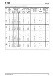
BLB 382 <strong>BLU</strong> <strong>3000.1</strong> - <strong>4000.1</strong> <strong>PR</strong>/<strong>MD</strong>Technical data<strong>BLU</strong> <strong>3000.1</strong> <strong>PR</strong>/<strong>MD</strong> <strong>BLU</strong> <strong>4000.1</strong> <strong>PR</strong>/<strong>MD</strong>Thermal power max. kW 3000 3900kcal/h 2.586.000 3.362.000Thermal power min. kW 630 875kcal/h 543.100 754.300Natural gas pressure mbar 40÷300 40÷300LPG pressure mbar 37÷150 37÷150Voltage , 50 Hz V 230 / 400 230 / 400Motor kW 5,5 7,5Rpm N° 2800 2800Fuel : P.c.i. Natural gas = 35,9 Mj / Nm 3 = 8.600 kcal / Nm 3P.c.i. GPL 22.260 kcal / Nm 3mbar1614OPERATING RANGE OF THE BURNERSOVERALL DIMENSIONSED - D1BACMIFLIO0123NGHOcombustion chamber pressure121086420<strong>BLU</strong> <strong>3000.1</strong><strong>BLU</strong> <strong>4000.1</strong>500 1000 1500 2000 2500 3000 3500 kcal/hx 1000500 1000 1500 2000 2500 3000 3500 4000 kWcapacityMODELS A B C D D1 E F G H I L M N OBlu <strong>3000.1</strong> 941 448 493 330 530 780 290 466 280 315 315 M16 195 250Blu <strong>4000.1</strong> 941 448 493 365 565 780 320 466 280 315 315 M16 195 250D= Short head D1= Long headpag.14
LB 382 <strong>BLU</strong> <strong>3000.1</strong> - <strong>4000.1</strong> <strong>PR</strong>/<strong>MD</strong>BCONNECTION TO THE GAS PIPELINEOnce connected the burner to the gas pipeline, it is necessary to control that this last is perfectly sealed. Also verify that the chimneyis not obstructed. Open the gas cock and carefully bleed the piping through the pressure gauge connector, then check the pressurevalue trough a suitable gauge. Power on the system and adjust the thermostats to the desired temperature. When thermostats close,the sealing control device runs a seal test of valves; at the end of the test the burner will be enabled to run the start-up sequence.ELECTRICAL CONNECTIONSAll burners factory tested at 400 V 50 Hz three-phase for motors and 230 V 50 Hz monophase with neutral for auxiliary equipment.If mains supply is 230 V 50 Hz threephase withuot neutral, change position of connectors on burner as in fig. Protect burnersupply line with safety fuses and any other devices required by safety standards obtaining in the country in question.BURNER START-UPOnce connected the burner to the gas pipe make sure that there are no leakages. Air bleed the pipe through the pressure gaugefixing point and check the pressure with a pressure gauge . Turn the thermostats to the desired temperature.<strong>PR</strong>ELIMINARY CHECKS- Before starting up the boiler check the following: - gas type and feed pressure; - gas valves closed;- the seals in the pipe fittings; - gas pipe breather and input pressure; - that the cable complies with the diagram and the phase andneutral wires correspond; - that the burner shuts down when the boiler thermostat opens;- the seal of the boiler furnace which preventsair from entering; - the seal on the flue-boiler pipe fitting; - the condition of the flue (sealed, free from blockage, etc ).If allthese conditions are present, start the burner. The control device starts the motor to carry out prewashing of the combustion chamber.During this prewash period (about 30 seconds) the device checks that air pressure is correct via the air pressure switch. At theend, it supplies power to the transformer and opens the gas valves. The flame must be lit and stabilize within 3 seconds, which isthe device's safety time limit. Check to ensure the flame is lit before placing any control instrument in the flue. Adjust and checkthe gas flow necessary for the boiler at the meter. Adjust the air flow according to the gas flow to obtain correct combustion.ADJUSTING THE COMBUSTION <strong>PR</strong>OCESSIMPORTANT: to obtain the right adjustment of the combustion and thermal capacity it is important to analyze the reducts ofcombustion with the aid of suitable instruments. The combustion and thermal capacity adjustment is done simultaneously,together with the analysis of the products of combustion, making sure that the measured values are suitable and that they complywith current safety standards. On this matter, please refer to the table and figure below.THESE OPERATIONS MUST BE DONE BY <strong>PR</strong>OFESSIONALLY-QUALIFIED TECHNICIANS.Natural GasCO2 9,6%CO
BLB 382 <strong>BLU</strong> <strong>3000.1</strong> - <strong>4000.1</strong> <strong>PR</strong>/<strong>MD</strong>Ref. DescriptionDurationt1 Duration Waiting time for confirmationt2 of air pressure8”t3 Preventilation time66”t4 Safety time2”t5 Pressurizing timeTime for enabling operation of themain gas valve on minimum capacity4”10”t6Time for enabling operation of themain gas valve on maximum capacityThe control box starts the burnerfan, to carry out the prepurging ofthe combustion chamber, andcheks the vent air pressure throughthe air pressure switch. At theend of prepurging, the ignitiontransformer cuts-in and generatesa spark between the electrodes. Atthe same time the two gas valvesLANDIS & STAEFA, Model LFL1.622 OPERATING CYCLE10”t1Pressostato Gas manostat gasMotore ventilatore Fan motorPressostato Air Switch ariaTrasformatoreIgnition di transformeraccensioneValvola Gas valve gasConsensomin./max. Min/max capacity potenzaenabling device100%Serranda aria minAir damper 0Gas Farfalla damper gasFlame Rivelazione detectordi fiammaCut-out Spia pilot di blocco lampCiclo Normal di funzionamento operating normale cyclet2t3open (Vs safety valve and Vl working valve). The total safety, in case of missed ignition or casual burner's flame-out,is granted by a ionisation probe which cuts-in and sets the burner shutdown within the safety time. In case of gaslack or a major pressure drop, the minimum air pressure switch shuts down the burner.t4t5t6Operating Ciclo di cycle funzionamento in the event ofignition in mancanza failureNormal di fiamma operating all'accensione cyclet1t2t3t4LANDIS & STAEFA SQM 50.481A2 AIR DAMPER MOTORRemove cover to gain access to the adjusting cams.The cams are to be adjusted through the suitable key provided for. Description:Cam VIIIis never usedI - High flame opening position adjusting cam (Air)II - Min. flame opening position adjusting cam (Air).III - Low flame opening position adjusting cam (Air)IV - Not used camV - Not used camVI - Not used camVII - Not used camVIII - Not used campag.16
+--LB 382 <strong>BLU</strong> <strong>3000.1</strong> - <strong>4000.1</strong> <strong>PR</strong>/<strong>MD</strong>BAIR ADJUSTMENTCOMMUTATORESELECTORAUTO0-Part. 1+Part. 2Part. 30 = operating bloccaggio elements degli apparati locked per il in an intermediateposition funzionamento in una posizione intermadia= operation funzionamento maximum alla massima capacity potenza= operation funzionamento minimum alla minima capacity potenzaAUTO = automatic funzionamento operation automaticoADJUSTING THE MINIMUM CAPACITY OF THE BURNER – AIR and GASPosition the selector placed on the control panel on position 2 and proceed as follows:Adjust the minimum gas flow rate using a suitable wrench, turn the butterfly valve until you reach the correct gas flow,as established by analyzing the combustion process.ADJUSTING THE MAXIMUM CAPACITY OF THE GASPosition the selector, situated on the control panel, on position 1 and proceed as follows:Adjusting the maximum gas flow rate (see figure on solenoid valve adjustments) or adjust the gas pressure in the governor.ADJUSTING THE MAXIMUM AIR FLOW RATEAdjusting the maximum air flow rate (see figure, detail 2). Loosen the nut holding the air damper transmission rod;The correct air flow as established by analyzing the combustion process.ADJUSTING THE INTERMEDIATE BURNER CAPACITYUsing the selector, start the servomotor (closing or opening) and position on 0 to stop the stroke; the adjustment ismade as outlined below. Repeat the operation for the other cam points.Adjustment the intermediate gas flow rates (see figure, detail 3): - using a suitable Allen wrench, change the position ofthe cam guide blade; if you screw it down, the flow rate is reduced; if you unscrew it, the flow rate increases.CALCULATING THE BURNER CAPACITYTo calculate the burner's capacity in kW, proceed as follows: Check the gas flow rate (in liters) onthe counter and the time of the reading in seconds.Proceed with the calculation using the following : e x f = kWsecfe = Litres gassec = Time in secondG20 = 34,02G30 = 116G31 = 88pag.17
502,55302520BLB 382 <strong>BLU</strong> <strong>3000.1</strong> - <strong>4000.1</strong> <strong>PR</strong>/<strong>MD</strong>COMBUSTION ADJUSTMENTWARNING: In order to have a correct combustion and thermal output adjustments, these must be carried out togetherwith a combustion analysis, to be executed through suitable devices, taking care that the values are the correct ones andare in accordance with the local safety regulations. The adjustments must be carried out by qualified and skilled techniciansauthorised by <strong>Ecoflam</strong> S.p.A.FIRING HEAD SETTING-+IGNITION ELECTRODEIgnition electrodeElettrodo di accensione7 mm4 mm7 mm""Ionization probeElettrodo di rivelazioneADJUSTMENT OF GAS MINIMUM <strong>PR</strong>ESSURE SWITCHUnscrew off and remove cover M. - Set regulator N to a value equal to 60% of gas nominal feed pressure(i.e. for nat. gas nom. pressure = 20 mbar, set regulator to a value of 12 mbar; for L.P.G. nom.pressure of G30/G31- 30/37 mbar, set regulator to a value of 18 mbar).Screw up cover MADJUSTMENT OF THE AIR <strong>PR</strong>ESSURE SWITCHUnscrew screws A and B and remove cover C.- Set the pressure switch to the minimum byturning regulator D to position 1.- Start the burner and keep in low flame running, while checking that combustion is correct.Through a small cardboard, progressively obstruct the air intake until to obtain a CO2 increase of0,5÷0,8% or else, if a pressure gauge is available, connected to pressure port E, until reaching apressure drop of 1 mbar (10 mm of W.G.). - Slowly increase the adjustment value of the airpressure switch until to have the burner lockout. Remove the obstruction from the air intake,screw on the cover C and start the burner by pressing the control box rearm button.Note: The pressure measured at pressure port E must be within the limits of the pressureBswitch working range. If not, loose the locking nut of screw F and gradually turn the same:clockwise to reduce the pressure; counterclockwise to increase. At the end tighten the locking nut.IAMCL3,0452,70,440N102,4D0,6G352,1151,80,91,51,2FHEpag.18
LB 382 <strong>BLU</strong> <strong>3000.1</strong> - <strong>4000.1</strong> <strong>PR</strong>/<strong>MD</strong>Bmin. 6 µAMicroamperometroMicroammeterfondo scala 50 µA50 µA end of scaleIONIZATION CURRENTThe ionization current is checked by inserting a microammeterwith an end of scale of 50 µA (d.c.) in series with theionization probe. A faulty position of the electrode can lead24to a reduction in the ionization current and cause a safetycut-out of the burner due to a flame detection failure. In thisLANDIS LFL1.622 case, check the position of the electrode, its electric connectionand the earthing of the burner.FIRING HEAD DISASSEMBLYDESCRIPTION OF THE CONTROL PANEL OF THE BURNERFABCDEI00AUTOA- main switch I / OB- fuseC- selector :0 = operating elements locked in anintermediate position= operation on maximum capacity= operation on minimum capacityAUTO = automatic operationD- thermal relaylock-out lampE - working lampF- reset keypag.19
BLB 382 <strong>BLU</strong> <strong>3000.1</strong> - <strong>4000.1</strong> <strong>PR</strong>/<strong>MD</strong>Display:analog input 1(actual value)Display: Set point SP1RWF 40 MICRO<strong>PR</strong>OCESSOR REGULATORDescription of display and keys on the RWF 40 microprocessor regulatorThe figure shows the normal display indicatingthe actual value and the programmed setpoint, and equally important,gives the meaning of thesingle keys and indicator Leds.Reduce powerCLOSE/1st StageBurner operationManual operationAuxiliary contactTwo-stage operationIncrease powerOPEN/2nd StageDecrease valueIncrease valueEXIT key.Programming key<strong>PR</strong>OGRAMMING LEVELSNormal displaymin 2sPGMPGM PGMUser LevelPGMmin 2sPGM PGMExitParameters levelPGMmin 2sPGMPGMConfiguration levelPGMpag.20
LB 382 <strong>BLU</strong> <strong>3000.1</strong> - <strong>4000.1</strong> <strong>PR</strong>/<strong>MD</strong>BSETTING PARAMETERSWhen the burner is ignited all displays of the regulator light up. The set point display will blink for about 10 seconds. The valuein the upper field of the display (red) indicates the actual value. The value in the lower field of the display (green) indicates the setpoint currently programmed.CHANGING THE SET POINTTo change the set point, proceed as follows: - Press the PGM button to access the user level. SP1* will appear in the lower display- Change the value of set point SP1 using the t and s keys.▼e ▲. - After a 2 second delay the value set is stored automatically – Toreturn to normal display press EXIT.* The value of SP1 depends on the value set previously in configuration level C111.SETTING PID PARAMETERSPID parameters are factory set to standard mean values. The operation of the regulator can be self-adapted to suit the system byactivating the “tunE” function. The regulator will set the PID parameters automatically. To activate the “tunE” function proceedas follows: - With the burner in operation, press PGM + ▼. - the caption “tunE*” will blink in the display. – When “tunE” stopsblinking, the self-adaptation routine has been completed. - Confirm the computed parameters by pressing the ▲ key for 2 seconds.* The “tunE” function cannot be activated in Manual mode, or when the burner is off.The PID parameters can be corrected manually from the parameters level, working on the proportional band Pb1, the derivativeaction time dt and the integral action time rt.To change parameters Pb1, dt and rt, proceeds as follows: - Press the PGM button to access the parameters level. - To move fromone parameter to the next, press PGM . - When Pb1 is displayed, the value can be increased or decreased using the s and t keys. -Confirm the changed parameters by pressing PGM. - If confirmation is not given within 2 seconds the value will be stored automatically.- Press PGM to access the next parameter. - When dt is displayed, repeat the procedure described above. - Press PGMto access the next parameter. - When rt is displayed, repeat the procedure above. - To return to normal display press EXIT.DIFFERENTIAL SETTING FOR IGNITION AND SHUTOFFThe regulator allows the selection of an adjustable switching differential that establishes burner ignition and shutoff values.HYS1 indicates the lower ignition limit, below which the regulator switches the burner to maximum power. HYS3 indicatesthe upper shutoff limit, above which the regulator switches the burner off. To set HYS1 and HYS3 proceed as follows: - Pressthe PGM key to access the parameters level. - To move from one parameter to the next, press PGM . - When HYS1 is displayed(burner ignition differential-stage II), increase or decrease the value using the ▼ and ▲ keys. - Confirm the changed parameters bypressing PGM. - If confirmation is not given within 2 seconds the value will be stored automatically. - Press PGM to access thenext parameter. - When HYS2 is displayed (burner shutoff differential-stage II), repeat the procedure described above. - PressPGM to access the next parameter. - When HYS3 is displayed (upper shutoff differential) repeat the procedure described above.- To return to normal display press EXIT.MANUAL/AUTOMATIC MODETo access “MANUAL” mode, press and hold EXIT for at least 5 seconds. Manual mode can only be selected when the burner isin operation. It is deactivated automatically when the burner shuts off. When the LED above the hand symbol is alight, the regulatoris in manual mode and the position of the servocontrol can be changed using the ▼ and ▲ keys. The LEDS on the front ofthe regulator indicate whether the servocontrol OPEN or CLOSE command is currently active. Pressing the ▼ key the servocontrolOPENS. Pressing the ▲ key the servocontrol CLOSES. To select automatic mode press and hold EXIT for at least 5 seconds.The LED above the hand symbol goes out and the regulator reverts to automatic.CLIMATIC COMPENSATIONThe RWF 40 regulator can be set with the set point interlocked to the external probe. To select this operating mode, proceed asfollows: - Connect the required probe as in the wiring diagram. - Change the regulator settings. When using an external probethe regulator must be set as follows: - Press the PGM key to access the configuration level. When the caption C111 (XXXX) isdisplayed, use the ▲ key to access the second figure (XXXX). Use the ▼ key to select the type of probe (XX3X). - Confirm thechange of parameters by pressing PGM. If this is not done within 2 seconds, the value is stored automatically - Press PGM toaccess the configuration level. When the display reads C112 (XXXX), use the ▲ key to access the second figure (XXXX). Press the▼ key to set the type of probe (XX3X). - Confirm the changed parameters by pressing PGM. - If confirmation is not givenwithin 2 seconds the value will be stored automatically.- To return to normal display press EXIT. To establish the heating curve, proceed as follows:- Press PGM to access the parameters level. - Press PGM to move from one parameter to the next. - When the letter H isdisplayed (heating curve gradient), increase or decrease the value using the ▼ and ▲ keys. - Confirm the changed parameters bypressing PGM. - If confirmation is not given within 2 seconds the value will be stored automatically.- To return to normal display press EXIT.pag.21
BLB 382 <strong>BLU</strong> <strong>3000.1</strong> - <strong>4000.1</strong> <strong>PR</strong>/<strong>MD</strong>Boiler temperature set point (iC)160140120100SPH8060SPL4020PARAMETERIZATION43.83.63.43.232.82.62.42.221.81.61.41.210.80.60.40.2Heating curve gradient (H)020 15 10 5 0 -5 -10 -15 -2017.5 12.5 7.5 2.5 -2.5 -7.5 -12.5 -17.5External temperature (iC)<strong>PR</strong>OBE CONNECTION DIAGRAMSCod. S721Cod.S704Connection for probeQAE2..(passive probe)Water probeConfiguration codeC111 = 9XXXRWF 40G1+ M11 2 3 4B MQAE22AConnection for probeFT-TP/..(passive probe)(Degusa probe)Configuration codeC111 = 5XXXCod.S731S731/1S731/2S731/3S731/4Connection for probeQBE620-P..(active probes)Configuration codeC111 = GXXXS731 - 0…4 bar / 0…400 kPaQBE620-P4S731/1 - 0…10 bar / 0…1 MPaQBE620-P10S731/2 - 0…16 bar / 0…1.6 MpaQBE620-P16S731/3 - 0…25 bar / 0…2.5 MPaQBE620-P25S731/4 - 0…40 bar / 0…4 MPaQBE620-P40pag.22RWF 40G+ G- M1 U11 2 3 4GL M U1OBE620-P..Cod.S720/1Connection for probeQAC22 (passive probe)Configuration codeC111 = XX3XC112 = XX1XB9RWF 401 2 3 4M9B MQAC2..
LB 382 <strong>BLU</strong> <strong>3000.1</strong> - <strong>4000.1</strong> <strong>PR</strong>/<strong>MD</strong>BC111 – C112 INPUT CONFIGURATION INDICATIONSAnalog input 1 (actual value)Pt1000, 2-wire, Landis & Staefa IEC 751 5FT-TP/… (passive probe)Ni1000, 2-wire, Landis & StaefaQAE2 … (passive probe - water probe)9Standard Signal DC 0…10 V QBE620P…(active probe - pressure probe) GAnalog Input 3 (external temperature)No function (probe not active) 0External probe Pt 1000, 2-wire,QAC22 (passive probe)1AUXILIARY CONTACT, TYPE OF REGULATOR, SET POINT “SP1”BLOCK C112. Parameter configurationSet point “SP1”Set point SP1 - data input from keys 0Set point SP1 - interlocked to external probe (configure) 1ERROR/FAULT INDICATIONNUMBERS BLINKING IN DISPLAY- Situation - The number 1999 blinks in the display as the actual value, with theset point value displayed normally.- Cause - The real value is not being measured. This means that the upper or lowerlimit of the measurement range on analog input 1 (real value) has been exceeded.- Remedy - Check the electrical connections and the state of the probe. If the probeis faulty, the regulator will not indicate the real value of the physical quantitymonitored. This will result in automatic shutdown (failsafe), deactivation of theself-adapt function and inhibition of manual operation. The response of theauxiliary contact will depend on the configuration of parameter C113.- Situation - The number 1999 blinks in the display as the actual value, with tAshowing in the set point field.- Cause - The external temperature is not being measured. This means that theupper or lower limit of the measurement range on analog input 3 (real value) hasbeen exceeded.- Remedy - Check the electrical connections and the state of the probe. If the probeis faulty, the regulator will not indicate the real value.- Situation - The number 1999 blinks in the display as the actual value, with SP .Eshowing in the set point field.- Cause - The external set point value is not being measured. This means that theupper or lower limit of the measurement range on analog input 2 (real value) hasbeen exceeded.- Remedy - Check the electrical connections and the external set point signal. If theprobe is faulty, the regulator will not indicate the real value of the physical quantitymonitored. This will result in automatic shutdown (failsafe), deactivation of theself-adapt function and inhibition of manual operation.pag.23
BLB 382 <strong>BLU</strong> <strong>3000.1</strong> - <strong>4000.1</strong> <strong>PR</strong>/<strong>MD</strong>WHEN REPLACEMENT IS NECESSARY, <strong>PR</strong>OCEED AS SHOWN IN FIGURES A-B-C BELOWABCInsert the RWF 40 regulator through the relative opening in the electrical panel (A).Insert the fixing anchors and screws into the slots, and secure the unit to the panel (B).To open the regulator, squeeze the cover from the ends as shown, and lift out (C).MAINTENANCEANNUAL CHECKThe burner (combustion head, electrodes, etc.) must be checked regularly by an authorized technician, once or twicea year, depending on how much it is used. Before proceeding withe the maintenance check-up on the burner, it isadvisable to check the general condition of the burner and take the following steps: Disconnect the burner (removethe plug).- Close the gas shut-off cock.- Remove the cover from the burner, clean the fan and air intake.- Clean the combustion head and check the position of the electrodes.- Re-install the parts.- Check the seal on the gas connectors.- Check the state of the flue.- Start the burner.- Check the combustion parametersBEFORE TAKING ANY ACTION, CHECK:- that there is power in the circit and the burner is connected;- that the gas pressure is right and the gas shut-off cock is open;- that the control systems are properly connected. If all these conditions have been satisfied, start the burner by pressingthe reset button. Check the burner cycle.IF THE BURNER FAILS TO START:check the switch, the thermostats, the motor and the gas pressure.IF THE BURNER <strong>PR</strong>OCEEDS WITH <strong>PR</strong>EVENTILATION BUT CUTS OUT AT THE END OF THE CYCLE:check the air pressure and the fan. Check the air pressure switch.IF THE BURNER <strong>PR</strong>OCEEDS WITH <strong>PR</strong>EVENTILATION BUT DOES NOT LIGHT:check the installation and position of the electrodes. Check the ignition cable.Check the ignition transformer. Check the safety device.IF THE BURNER LIGHTS BUT CUTS OUT AFTER THE SAFETY INTERVAL:check that the phase and neutral wires are connected correctly.Check the gas solenoid valve. Check the position and connection of the detector electrode.Check the detector electrode. Check the safety device.IF THE BURNER LIGHTS BUT CUTS OUT AFTER OPERATING FOR A FEW MINUTES:check the pressure regulator and gas filter. Check the gas pressure with a pressure gauge. Check the detector value (atleast 6 µA).pag.24
LB 382 <strong>BLU</strong> <strong>3000.1</strong> - <strong>4000.1</strong> <strong>PR</strong>/<strong>MD</strong>BPARAMETERSParameter Display <strong>Ecoflam</strong> setting <strong>Ecoflam</strong> setting <strong>Ecoflam</strong> setting(passive probe) (passive probe) (active probe)QAE22 FT-TP/1000 QBE620-P...Limit value of limit comparator AL 0 0 0Switching differential for limit comparator HYSt 0 0 0Proportional band Pb.1 8 8 1Derivative time dt 20 20 3Integral action time rt 80 80 15Dead band (neutral zone) db 0.5 0.5 0.5Actuator running time (sec.) tt 25 25 25Switch-on threshold burner / stage II HYS1 -2 -2 -0.2Switch-off level stage II HYS2 0 0 0Upper switch-off threshold HYS3 5 5 0.5Response threshold q 0 0 0Heating curve slope H 2 2 2Parallel displacement P 0 0 0CONFIGURATIONParameter Display <strong>Ecoflam</strong> setting(passive probe) (active probe) QBE620-P...QAE22 FT-TP/1000 -P4 -P10 -P16 -P25 -P40Analog input 1, 2 and 3; setpointchangeover / shift C111 9030 5030 G000 G000 G000 G000 G000Limit comparator; controller type;setpoint 1; locking C112 0010 0010 0010 0010 0010 0010 0010Unit address; decimal place / unit,signal for out-of-range C113 0110 0110 0110 0110 0110 0110 0110Measured value range start analoginput 1 SCL 0 0 0 0 0 0 0Measured value rangeanalog input 1 SCH 100 100 4 10 16 25 40Measured value rangeanalog input 2 SCL2 0 0 0 0 0 0 0Measured value rangeanalog input 2 SCH2 0 0 0 0 0 0 0Lower setpoint limit SPL 60 60 0 0 0 0 0Upper setpoint limit SPH 88 88 4 10 16 25 40Actual value correction,analog input 1 OFF1 0 0 0 0 0 0 0Actual value correction,analog input 2 OFF2 0 0 0 0 0 0 0Actual value correction,analog input 3 OFF3 0 0 0 0 0 0 0Filter time constant for digital filter, dF1 1 1 0 0 0 0 0analog input 1pag.25
CLB 382 <strong>BLU</strong> <strong>3000.1</strong> - <strong>4000.1</strong> <strong>PR</strong>/<strong>MD</strong>Caracteristiques du bruleur<strong>BLU</strong> <strong>3000.1</strong> <strong>PR</strong>/<strong>MD</strong> <strong>BLU</strong> <strong>4000.1</strong> <strong>PR</strong>/<strong>MD</strong>Puissance termique max. kW 3000 3900kcal/h 2.586.000 3.362.000Puissance termique min. kW 630 875kcal/h 543.100 754.300Pression gaz naturel mbar 40÷300 40÷300Pression LPG mbar 37÷150 37÷150Tension d’alimentation 50 Hz V 230 / 400 230 / 400Moteur kW 5,5 7,5Tours par minute N° 2800 2800Combustible : P.c.i. gaz naturel = 35,9 Mj / Nm 3 = 8.570 kcal / Nm 3P.c.i. GPL 22.260 kcal / Nm 3mbar16COURBE DE TRAVAILContrepression en chambre de combustion141210864205001000E<strong>BLU</strong> <strong>3000.1</strong>Puissance brûleurDIMENSIONS D'ENCOMBREMENTD - D1BACMIFLIO0123NGHO<strong>BLU</strong> <strong>4000.1</strong>500 1000 1500 2000 2500 3000 3500 kcal/hx 10001500 2000 2500 3000 3500 4000kWMODELE A B C D D1 E F G H I L M N OBlu <strong>3000.1</strong> 941 448 493 330 530 780 290 466 280 315 315 M16 195 250Blu <strong>4000.1</strong> 941 448 493 365 565 780 320 466 280 315 315 M16 195 250D= tête courte D1= tête longuepag.26
LB 382 <strong>BLU</strong> <strong>3000.1</strong> - <strong>4000.1</strong> <strong>PR</strong>/<strong>MD</strong>CCONNEXION AU RESEAU GAZUne fois que le brûleur est connecté à la tuyauterie gaz, il faudra s’assurer que cette dernière soit parfaitement étanche, et que lacheminée ne soit pas obstruée. Une fois ouvert le robinet du gaz, purger très soigneusement la tuyauterie par la prise de pression, etcontrôler, ensuite, la valeur de la pression a l'aide d'un manometre. Brancher le système et régler les thermostats à la températuredésirée. A la fermeture des thermostats, le dispositif de contrôle d’étancheité, effectuera un essais des vannes. Au bout de l'essai, lebrûleur obtiendra le consensus pour le démarrage.CONNEXION ELECTRIQUETous les brûleurs sont essayés à 400 V, 50 Hz triphasé, avec neutre pour les auxiliaires. Dans le cas où il fût nécessaire alimenter lesbrûleurs à 230 V, 50 Hz triphasé sans neutre, effectuer les modifications nécessaires suivant le schéma electrique du brûleur et contrôlerque le relais thermique soit dans la plage d’absorption du moteur. Vérifier, en outre, le sens de rotation du ventilateur.DEMARRAGE DU BRULEURAvant de démarrer le brûleur, s`assurer qu`il soit installé correctement. Vérifier les connexions électriques suivant les plans ainsi quela tuyauterie du système. Avant d`effectuer les connexions électriques~ veiller à ce que le voltage corresponde aux données indiquéessur la plaquette des caractéristiques techniques. Le schéma de la connexion électrique, ainsi que le cycle de démarrage~ sont illustrésséparément. Pour connecter l'appareillage au brûleur, suivre le schéma. Veiller soigneusement à la connexion du neutre et la phase:jamais les inverser. Contrôler la connexion à terre du système. Avec les moteurs triphasés, vérifier le sense giratoire (voir la flèche).Purger l'air et les impuretés de la tuyauterie du gaz, et vérifier que la préssion du gaz soit dans les limites indiquées sur la plaquette.Ce contrôle doit être effectué à l'aide d'un manomètre à gaz connecté à la prise de pression correspondante du brûleur. On démarrele moteur et il commence la preventilation. Le motoréducteur porte le volet de l'air à l`ouverture maximale dans 30 secondes. Lorsque le motoréducteur est complètement ouvert, un signal transmis au dispositif de contrôle démarre un cycle de pre-ventilation de60 secondes env. A la fin de cette dernière, le motoréducteur portera le volet en petite allure, ainsi permettant l`allumage du brûleurà la portée minimale. En même tempst on a l`alimentation du transformateur d'allumage et, après 3 secondes (pre-allumage) onaura l’alimentation des vannes du gaz. A ce point, la vanne à papillon règle la portée du gaz dans la tête de combustion. Deuxsecondes après l'ouverture des vannes, le transformateur est exclus du circuit. En cas de faute d`allumage, le brûleur va en blocagedans deux secondes. Le brûleur est allumé à la puissance minimale (env. 30% de la puissance maximale). Le dispositif modulateur(si prévu) fera ouvrir le servomoteur à la puissance maximale, ou bien il l'arrêtera à la puissance intermédiaire requise par le système.L`ouverture du servomoteur fera ouvrir gaz et air en manière proportionnelle, de façon à avoir une combustion optimale à toutesles portées (30% - 100%). A la fin du fonctionnement le servomoteur se porte en position de fermeture.CONSEILS IMPORTANTS:Tous les organes réglables doivent être fixés par l’installateur après les réglages. Contrôler la combustion dans la cheminéeà chaque réglage. Les valeurs de CO2 doivent être d’environ 9,7 (G20) - 9,6 (G25) - 11,7 (l3B) - 11,7 (l3P) et leREGLAGE DE LA COMBUSTIONATTENTION : por obtenir un réglage correct de la combustion et du débit thermique, il faut effectuer l'analyse des fuméesen utilisant les instruments appropriés. Le réglage de la combustion et du débit thermique doit être fait en même temps qu’uneanalyse des produits de combustion, en veillant à ce que les valeurs relevées soient correctes, et qu’elles répondent toujours auxnormes de sécurité en vigueur.CETTE OPÉRATION DOIT ETRE FAITE PAR DU LA PERSONNEL QUALIFIÉ ET AUTORISÉ PAR LASOCIÉTÉ ECOFLAM SPA .Gaz Nat.CO2 9,6%CO
CLB 382 <strong>BLU</strong> <strong>3000.1</strong> - <strong>4000.1</strong> <strong>PR</strong>/<strong>MD</strong>Ref. Descriptiont1 Temps de contrôle du pressostat airt2t3t4t5t6Temps de pre-ventilationTemps de securitéTemps de pre-allumagetempo per il consenso di funzionam.alla minima potenza della valvola dilavoro del combustibile.tempo per il consenso di funzionam.alla massima potenza della valvola dilavoro del combustibileLe coffret de sécurité démarre laturbine et commence le pre-balayagede la chambre de combustion.Le pressostat air contrôle la pressionde l’air de ventilation afin quele fonctionnement soit correct. A lafin du pre-balayage le transformateurd’allumage s’enclenche, parCOFFRETS DE SECURITE LANDIS & STAEFA MOD. LFL1.622Temps8”66”2”4”10”10”t1Pressostato gas gazMotore ventilatore MoteurPressostato aria airTransformateurTrasformatoredi accensioneSoupape Valvola gas gazConsentimientoConsensomín. min./max. / máx. potencia potenza100%Serranda ariaCierre del aire min0Farfalla gasCierre del gazSonde Rivelazione à ionisationdi fiammaLampe de mise enSpia di sécurité bloccoCycle Ciclo de di fonctionnement funzionamento normale normalt2une étincelle entre les éléctrodes, suivi par les les vannes gaz (soupape de sécurité VS et soupape de travail VL). En casde faute d’allumage ou coupure accidentelle du brûleur la sonde à ionisation met le brûleur en sécurité dans le temps desécurité. En cas de coupure du gaz ou de baisses de pression, le pressostat du gaz de pression minimum coupe le fonctionnementdu brûleur.t4t5t3t6Cycle de fonctionnement Ciclo di funzionamento par manquein mancanza de flamme di fiamma d'allumage all'accensionet1t2t3t4SERVOMOTEUR LANDIS & STAEFA SQM 50.481A2Enlever le couvercle pour avoir accès aux cames de régulation. La régulation des cames doit être faite à l’aide de la clé endotation. Description:Came VIIInon utiliséI - Came de régulation de la position d’ouverture en grande Allure.II - Came de régulation de la position du clapet de l’air à la coupure.III - Came de régulation de la position d’ouverture en min. Allure.IV - Came de régulation de la position d’ouverture en petite Allure.V - Came de régulation libre (non utilisé)VI - Came de régulation libre (non utilisé)VII - Came de régulation libre (non utilisé)VIII - Came de régulation libre (non utilisé)pag.28
+--LB 382 <strong>BLU</strong> <strong>3000.1</strong> - <strong>4000.1</strong> <strong>PR</strong>/<strong>MD</strong>CREGLAGES DES DEBITS AIR ET GAZCOMMUTATEURCOMMUTATOREAUTO0-Part. 1+Part. 2Part. 30 = bloccaggio blocage du degli servomoteur apparati per dans il une positionintermédiairefunzionamento in una posizione intermadia= funzionamento fonctionnement alla à massima la puissance potenza maximale= funzionamento fonctionnement alla à minima la puissance potenzaminimaleAUTO = fonctionnement funzionamento automatico automatiqueREGLAGE DE LA PUISSANCE MINIMALE DU GAZPositionner le commutateur qui se trouve dans le tableau de borde, dans la position 2 et agir comme il suit:Pour regler le débit minimale du gaz agir avec la clé à six pans sur la vis de la camme et modifier l’angle duclapet gaz de la vanne à papillon.REGLAGE DE LA PUISSANCE MAXIMALE DU GAZPositionner le commutateur qui se trouve dans le tableau de borde, dans la position 1 et agir comme il suit:Pour regler le débit maximale du gaz agir sur l’électrovanne de reglage jusqu’à obtenir le débit correct pour lachaudière.REGLAGE DU DÉBIT MAXIMALE DE L’AIR- Desserrer la vis de fixation de la tige et placer la même dans la position correcte.A la fin du reglage resserrer la vis de la tige.REGLAGE DES PUISSANCES INTERMEDIAIRES DU GAZActionner le servomoteur avec le commutateur (ouvert / fermé) e placer sur la position 0 pour l’arreter. Pourle reglage, agir comme il suit. Repeter les passages pour les autres points des cammes.Reglage des débits intérmediaires du gaz (voir immage, partie 3):- Avec une clé à six pans, modifier la position de la lame guide de la camme; serrant le débit augmente, desserrantle démit diminue.CALCUL DU DEBIT DE FONCTIONNEMENT DU BRULEURPour calculer le débit de fonctionnement, en kW, du brûleur, procéder de la manière suivante:- Vérifier au compteur la quantité de litres débités, ainsi que la durée de la lecture, ensuite procéderau calcul du débit par la formule suivante:e x f = kWse = Litres de gazs = Temps en secondesG20 = 34,02G25 = 29,25G30 = 116G31 = 88fpag.29
502,55302520CLB 382 <strong>BLU</strong> <strong>3000.1</strong> - <strong>4000.1</strong> <strong>PR</strong>/<strong>MD</strong>REGULATION DE LA COMBUSTIONATTENTION: Afin d’obtenir une correcte régulation de la combustion et de la portée thermique, celles-ci doivent êtreeffectuées en même temps à une analyse de la combustion, à se faire par des instruments opportuns, en vérifiant que lesdonnées sont correctes et correspondantes aux normes de sécurité locales. Les opérations de régulations doivent êtreeffectuées par des techniciens experts et qualifiés, autorisés par <strong>Ecoflam</strong> S.p.A.REGULATION DE LA TETE DE COMBUSTION-+POSITION DES ELECTRODESElectrode d’allumageElettrodo di accensione7 mm4 mm7 mm""Sonde de ionisationElettrodo di rivelazioneREGLAGE DU <strong>PR</strong>ESSOSTAT GAZ DE MINIMU<strong>MD</strong>évisser les vis I et L et enlever le couvercle M. - Positionner le régulateur N à un valeur équivalentau 60% de la pression nominale d’alimentation du gaz(par ex.: pour gaz nat. avec pression nom.de 20 mbar, positionner le régulateur à une valeur de 12 mbar; pour G.L.P. avec pressionMnom. G30/G31 30/37 mbar, positionner le régulateur à 18 mbar). - Remonter le couvercleM et visser les vis I et L.I4540N103515REGULATION DU <strong>PR</strong>ESSOSTAT AIRLDévisser les vis A et B et enlever le couvercle. Réguler le pressostat air au minimum en tournant le régulateurD en position 1. Démarrer le brûleur en 1e allure et effectuer une analyse de la combustion.A l’aide d’un petit carton obstruer progressivement le conduit d’aspiration de l’air jusqu’àobtenir une augmentation de CO2 de 0,5÷0,8% ou bien, si l’on dispose d’un manomètre connectéà la prise de pression E, jusqu’à obtenir une chute de pression de 1 mbar (10 mmAC.E.). Augmenter progressivement la valeur de la régulation du pressostat jusqu’à obtenirl’arrêt en sécurité du brûleur. Enlever l’obstruction du conduit, visser le couvercle C etBdémarrer le brûleur en appuyant sur la touche de réarmement du coffret de sécurité.Note: La pression mesurée à la prise de pression E doit être comprise dans les limites de la plage de travaildu pressostat. Sinon, dévisser l’écrou de blocage de la vis F et la tourner graduellement: à droite pour réduire la pression;à gauche pour l’augmenter. Enfin serrer l’écrou de blocage.C3,02,70,42,4D0,6G2,11,80,91,51,2FHEpag.30
LB 382 <strong>BLU</strong> <strong>3000.1</strong> - <strong>4000.1</strong> <strong>PR</strong>/<strong>MD</strong>CCONTROLE SYSTEME DETECTION DE FLAMMEmin. 6 µAMicroamperometrofondo scala 50 µA24LANDIS LFL1.622Avec le brûleur énteint, brancher un microamperomètreà courante continue scale 50 µA. Si positionèerronéament, l’électrode peut provoquerl’arrêt du brûleur. Il faut bien contrôler la positionde l’electrode, les branchements eletriques et la miseà la masse du brûleur. La valeur doit être stable etjamais inférieure à 20 µA.ENLEVEMENT DE LA TETE DE COMBUSTIONDESCRIPTION DU TABLEAU DE COMMANDE DES BRULEURSFABCDEI00AUTOA- InterrupteurB- fusibleC- commutateur0 = blocage des dispositifs pour lefonctionnement d'une position intermédiaire= fonctionnement à la puissance maximale= fonctionnement à la puissance minimaleAUTO = fonctionnement automatiqueD - lampe de securitéE - lampe de fonctionnementF - touche de réarmementpag.31
CLB 382 <strong>BLU</strong> <strong>3000.1</strong> - <strong>4000.1</strong> <strong>PR</strong>/<strong>MD</strong>Affichage àcristaux liquides:Entrée analogique1 (valeur réelle)Affichage àcristaux liquides:consigne SP1REGULATEUR COMPACT UNIVERSEL RWF40Déscription de l’affichage à cristaux liquides (display) et des touches du regulateur RWF40Signal de commande« FERMETURE »du servomoteurSignal commandemanuelle« MARCHE/ARRET »Contact auxiliaireFonctionnementdu brûleurSignal de commande« OUVERTURE »du servomoteurReduction de la valeurSignal du fonctionnementdu brûleur à 2 alluresAugmentationde la valeurTouche sortie (EXIT)Touche deprogrammation (PGM)NIVEAUX DE <strong>PR</strong>OGRAMMATIONAffichage à cristauxliquides ordinairemin 2sPGMPGM PGMNiveau utilisateurPGMmin 2sPGM PGMExitNiveau paramètresPGMmin 2sPGMPGMNiveau configurationPGMpag.32
LB 382 <strong>BLU</strong> <strong>3000.1</strong> - <strong>4000.1</strong> <strong>PR</strong>/<strong>MD</strong>CINTRODUCTION DES PARAMETRESA l’allumage du brûleur tous les LED sur la façade sont allumés. L’ affichage à cristaux liquides (display) du consigne clignoterapour environ 10sec. L’affichage à cristaux liquides supérieur (rouge) indique la valeur mesurée et pendant le reglage, il indique lesparamètres entrés; celui inférieur (vert) indique la consigne.REGLAGE DE LA CONSIGNEPour regler la consigne il faut agir comme il suit.: - Avec la touche PGM on joint le niveau utilisateur, sur l’ affichage à cristauxliquides est visualisée SP1*. - Modifier la valeur de la consigne SP1 avec les touches ▼et ▲. - Après 2sec. La valeur consignée estautomatiquement mise en memoire. - Pour retourner dans le premier affichage touche EXIT.* La valeur SP1 dépend de la valeur consignée dans le niveau de configuration C111.CONSIGNE DES PARAMETRES PIDLes paramètres PID sont déjà reglés pendant l’installation sur le brûleur avec valeurs standards. Il est possible d’adapter le fonctionnementdu régulateur selon l’installation activant “auto-adaptation” “tunE” clignotant. Le regulateur calcule lui même les paramètresde regulation PID. Pour activer la fonction “tunE” il faut agir comme il suit: - démarrer “auto-adaptation” avec la touchePGM + ▼avec le brûleur en fonction. - Sur l’affichage apparaîtra “tunE*” clignotant. - Quan elle ne clignotera pas “auto-adaptation”seraterminée. - Confirmer les paramètres enforçant la touche ▲pour 2 sec..* “tunE” ne peut pas etre actué quand le regulateur est en fonctionnement manuelle ou avec le brûleur arreté.Les paramètres PID peuvent être modifiés manuellement au niveau paramètres agissant sur la bande proportionnelle Pb1,temps de dosage de dérivation dt et temps de dosage d’ intégration rt.Pour modifier les paramètres Pb1, dt, rt il faut agir comme il suit : - On accede au niveau paramètres par la touche PGM . - Onaccede au paramètres suivant toujours par la touche PGM. - Quand l’affichage indique Pb1. - On augmente ou diminue lavaleur par les touches ▼et ▲. - Confirmer les paramètres par la touche PGM, la valeur est quand même memorisée dans 2sec. -On accede au paramètre suivant par la touche PGM . - Quand l’affichage indique dt l’on peut repeter les instructions précédentes- On accede au paramètre suivant toujour par la touche PGM - Quand l’affichage indique rt l’on peut repeter les instructionsprécédentes - On retourne au premier affichage par la touche EXIT.REGLAGE DU DIFFERENTIELLe régulateur permet de afficher une valeur différentielle de commutation reglable qui permet la marche et l’arrêt du brûleur.Avec HYS1 on indique la limite inférieure sous laquelle le brûleur se met en marche.Avec HYS3 on indique la limite supérieure sur laquelle le brûleur s’arrête.Pour afficher des valeurs de consigne à HYS1 et HYS3 il faut agir comme il suit: - On accede au niveau paramètres par la touchePGM . - On accede au paramètres suivant toujours par la touche PGM. - Quand l’affichage indique HYS1 (différentiel d’allumage)- On augmente ou diminue la valeur par les touches ▼et ▲. - Confirmer les paramètres par la touche PGM, la valeur estquand même memorisée dans 2sec. - On accede au paramètre suivant par la touche PGM . - Quand l’affichage indique HYS2(différentiel d’arrêt) l’on peut repeter les instructions précédentes - On accede au paramètre suivant toujour par la touche PGM.- Quand l’affichage indique HYS3 (différentiel supérieur d’arrêt) l’on peut repeter les instructions précédentes- On retourne au premier affichage par la touche EXIT.FONCTIONNEMENT MANUEL/AUTOMATIQUEOn accede au fonctionnement « MANUEL » appuyant la touche EXIT pour 5sec. Le fonctionnement manuel peut être mis enroute seulement quand le brûleur est en marche, il est automatiquement mis hors de service quand le brûleur s’arrête. Quand lerégulateur est en fonctionnement manuel (LED sur le symbole de la main allumé) l’on peut modifier la position du servomoteurpar les touches ▼et ▲. Les LED allumés sur la façade du régulateur indiquent si la commande OUVRE ou FERME du servomoteurest activé. Appuyant la touche ▲ le servomoteur ouvre; appuyant la touche ▼ le servomoteur ferme. Appuyant la toucheEXIT pour 5sec. On passe au fonctionnement automatique ; le LED sur le symbole de la main s’éteint et le régulateur est en fonctionnementautomatique.COMPENSATION CLIMATIQUELa compensation climatique est utilisée seulement dans le cas où une sonde extérieure soit branchée. Si le brûleur est utilisé avecune chaudière à vapeur, la compensation climatique n’est pas utilisée.pag.33
CLB 382 <strong>BLU</strong> <strong>3000.1</strong> - <strong>4000.1</strong> <strong>PR</strong>/<strong>MD</strong>Consigne température chaudière (°C)160140120100SPH8060SPL4020PARAMETRISATION43.83.63.43.232.82.62.42.221.81.61.41.210.80.60.40.2Pente courbe de chauffage ( H )020 15 10 5 0 -5 -10 -15 -2017.5 12.5 7.5 2.5 -2.5 -7.5 -12.5 -17.5température éxtérieure (°C)Cod. S721Cod.S704Branchement sondeQAE2..(sonde passive)Sonde eauCode C111 = 9XXXRWF 40G1+ M11 2 3 4B MQAE22ABranchement sondeFT-TP/..(sonde passive)Code C111 = 5XXXSchéma de branchement avec les sondesCod.S731S731/1S731/2S731/3S731/4Branchement sondeQBE620-P..(sonde active)CodeC111 = GXXXS731 - 0…4 bar / 0…400 kPaQBE620-P4S731/1 - 0…10 bar / 0…1 MPaQBE620-P10S731/2 - 0…16 bar / 0…1.6 MpaQBE620-P16S731/3 - 0…25 bar / 0…2.5 MPaQBE620-P25S731/4 - 0…40 bar / 0…4 MPaQBE620-P40pag.34RWF 40G+ G- M1 U11 2 3 4GL M U1OBE620-P..Cod.S720/1Branchement sondeQAC22 (sonde passive)Code C111 = XX3XC112 = XX1XB9RWF 401 2 3 4M9B MQAC2..
LB 382 <strong>BLU</strong> <strong>3000.1</strong> - <strong>4000.1</strong> <strong>PR</strong>/<strong>MD</strong>CINDICATION DE CONFIGURATION ENTREES C111-C112Entrée analogique 1 (valeur réelle)Pt1000, 2 fils, Landis & Staefa IEC 751FT-TP/...(sonde passive )5Ni1000, 2 fils, Landis & StaefaQAE2... (sonde passive sonde eau )9Signal standard DC 0...10 V QBE620-P...(sonde active, sonde de préssion) GEntrée analogique 3 (température éxtérieure)Aucune fonction (sonde non active) 0Sonde éxtérieure Pt 1000, 2 fils,QAC22 (sonde passive)1CONTACT AUXILIAIRE, TYPE DE REGULATEUR CONSIGNE “SP1”BLOCAGE C112. Configuration des paramètresConsigne “SP1”Consigne SP1 consigne des données avec touches 0Consigne SP1 configuration avec sonde éxtérieure 1SIGNALATION DES FAUTES ET D’ ANOMALIESCLIGNOTEMENT DU NUMERO SUR L’AFFICHAGE A’ CRISTAUX LIQUIDES (DISPLAY)- Situation - L’affichage de la valeur réelle indique 1999 clignotant et sur l’affichagede consigne il y a la valeur consignée.- Cause - La valeur réelle n’est pas mesurée. Ça signifie que la valeur du champs detravail de l’entrée analogique 1 (valeur réelle) a étée dépassée (plus haut ou plus bas).- Remède - Vérifier les branchements éléctriques et l’integrité de la sonde. Dans lecas où la sonde soit détériorée, le régulateur ne revèle pas la valeur réelle à contrôler etil éteint le brûleur automatiquement pour securité; il désactive l’auto-adaptation ainsique le fonctionnement manuel.Le contact auxiliaire repond sélon la configuration du paramètre C113- Situation - L’affichage de la valeur réelle indique 1999 clignotant et l’affichage deconsigne indique tA.- Cause - La température éxtérieure n’est pas mesurée. Ça signifie que la valeur duchamps de travail de l’entrée analogique 3 (valeur réelle) a étée dépassée (plus haut ouplus bas).- Remède - Vérifier les branchements éléctriques et l’integrité de la sonde. Dans lecas où la sonde soit détériorée, le régulateur ne revèle pas la valeur réelle.- Situation - L’affichage de la valeur réelle indique 1999 clignotant et l’affichage deconsigne indique SP .E.- Cause - La valeur de la consigne n’est pas mesurée. Ça signifie que la valeur duchamps de travail de l’entrée analogique 2 (valeur réelle) a étée dépassée (plus haut ouplus bas).- Remède - Vérifier les branchements éléctriques et le signal de la consigne extérieure.Dans le cas où la sonde soit détériorée, le régulateur ne revèle pas la valeur réelle àcontrôler et il éteint le brûleur automatiquement pour securité; il désactive l’autoadaptationainsi que le fonctionnement manuel.pag.35
CLB 382 <strong>BLU</strong> <strong>3000.1</strong> - <strong>4000.1</strong> <strong>PR</strong>/<strong>MD</strong>ASUBSTITUTION DU REGULATEURBCLes déscriptions A,B,C indiquent comme l’on doit démonter et remonter le régulateurRWF40.C – Pour enlever le régulateur, exercer une pression sur le couvercle et enléver le même.A – Introduire le régulateur RWF40 dans l’ouvertureB – Introduire les vis tamponées dans les fentes et les fixer sur le panneau.MAINTENANCECONTROLE ANNUELLe contrôle périodique du brûleur (tête de combustion, électrodes, etc.) doit être effectué, par un technicien autorisé, une ou deuxfois par an, suivant l’utilisation. Avant de procéder au contrôle pour la maintenance du brûleur, il est souhaitable de contrôler l’étatgénéral du brûleur et d’effectuer les opérations suivantes:- Débrancher le brûleur (enlever la prise). - Fermer le robinet d’arrivée du gaz. - Enlever le couvercle du brûleur, nettoyer le ventilateuret l’aspiration de l’air. - Nettoyer la tête de combustion et contrôler la position des électrodes. - Remonter les pièces.- Contrôler l’étanchéité des raccords gaz. - Contrôler la cheminée. - Faire redémarrer le brûleur. - Contrôler les paramètres de lacombustion (CO2 = 9,7 (G20); 9,6 (G25); 11,7 (G30); 11,7 (G31), (C0 = inférieur à 75 p.p.m.).AVANT CHAQUE INTERVENTION CONTROLER :- Qu’il y ait du courant électrique dans l’installation et que le brûleur soit branché. - Que la pression du gaz soit correcte et que lerobinet d’arrivée du gaz soit ouvert. - Que les systèmes de contrôle soient branchés correctement. - Si toutes ces conditions sontaccomplies, faire démarrer le brûleur en appuyant sur le bouton de déblocage. Contrôle le cycle du brûleur.LE BRULEUR NE DEMARRE PAS :- Contrôler l’interrupteur, les thermostats, le moteur, la pression du gaz.LE BRULEUR EFFECTUE LE <strong>PR</strong>EBALAYAGE ET SE BLOQUE A LA FIN DU CYCLE:- Contrôler la pression de l’air et le ventilateur. - Contrôler le pressostat de l’air.LE BRULEUR EFFECTUE LA <strong>PR</strong>EBALAYAGE ET NE S’ALLUME PAS:- Contrôler le montage et la position des électrodes. - Contrôler le câble d’allumage. - Contrôler le transformateur d’allumage.- Contrôler le coffret de sécurité.LE BRULEUR S’ALLUME ET SE BLOQUE A<strong>PR</strong>ES LE TEMPS DE SECURITE- Contrôler que la phase et le neutre soient branchés correctement. - Contrôler l’électrovanne du gaz. - Contrôler la position del’électrode de détection et son branchement. - Contrôler l’électrode de détection. - Contrôler le dispositif de sécurité.LE BRULEUR S’ALLUME ET SE BLOQUE A<strong>PR</strong>ES QUELQUES MINUTES DE FONCTIONNEMENT:- Contrôler le régulateur de pression et le filtre du gaz. - Contrôler la pression du gaz avec un manomètre. - Contrôler la valeur dedétection (6 µA min.).pag.36
LB 382 <strong>BLU</strong> <strong>3000.1</strong> - <strong>4000.1</strong> <strong>PR</strong>/<strong>MD</strong>CPARAMETRESParametro Display Valore impostato Valore impostato Valore impostato(sonda passiva) (sonda passiva) (sonda attiva)QAE22 FT-TP/1000 QBE620-P...Valore limite del contatto ausiliario AL 0 0 0Differenziale di commutazione del contatto ausiliario HYSt 0 0 0Banda proporzionale Pb.1 8 8 1Tempo dell’azione derivata dt 20 20 3Tempo dell’azione integrale rt 80 80 15Banda morta db 0.5 0.5 0.5Tempo di corsa del servocomando (sec.) tt 25 25 25Differenziale di accensione bruciatore/II stadio HYS1 -2 -2 -0.2Differenziale di spegnimento del II stadio HYS2 0 0 0Differenziale superiore di spegnimento HYS3 5 5 0.5Soglia di reazione q 0 0 0Pendenza della curva di riscaldamento H 2 2 2Spostamento parallelo P 0 0 0CONFIGURATIONParametro Display Valore impostato(sonda passiva) (sonda attiva) QBE620-P...QAE22 FT-TP/1000 -P4 -P10 -P16 -P25 -P40Ingresso analogico1,2 e 3;commutazione/modifica del setpoint C111 9030 5030 G000 G000 G000 G000 G000Contatto ausiliario; tipo di regolatore;setpoint 1;blocco C112 0010 0010 0010 0010 0010 0010 0010Indirizzo; cifra decimale/unità di misura;segnale per fuori scala C113 0110 0110 0110 0110 0110 0110 0110Indirizzo scala ingresso analogico 1(valore min. sonda) SCL 0 0 0 0 0 0 0Fine scala ingresso analogico1(valore max. sonda) SCH 100 100 4 10 16 25 40Indirizzo scala ingresso analogico 2(valore min. sonda) SCL2 0 0 0 0 0 0 0Fine scala ingresso analogico2(valore max. sonda) SCH2 0 0 0 0 0 0 0Limite inferiore setpoint SPL 60 60 0 0 0 0 0Limite superiore setpoint SPH 88 88 4 10 16 25 40Correzione del valore reale ingresso analogico 1 OFF1 0 0 0 0 0 0 0Correzione del valore reale ingresso analogico 2 OFF2 0 0 0 0 0 0 0Correzione del valore reale ingresso analogico 3 OFF3 0 0 0 0 0 0 0Costante di tempo del filtro digitale, dF1 1 1 0 0 0 0 0ingresso analogico 1pag.37
DLB 382 <strong>BLU</strong> <strong>3000.1</strong> - <strong>4000.1</strong> <strong>PR</strong>/<strong>MD</strong>Caracteristicas tecnicas<strong>BLU</strong> <strong>3000.1</strong> <strong>PR</strong>/<strong>MD</strong> <strong>BLU</strong> <strong>4000.1</strong> <strong>PR</strong>/<strong>MD</strong>Potencia térmica máx. kW 3000 3900kcal/h 2.586.000 3.362.000Potencia térmica mín. kW 630 875kcal/h 543.100 754.300Presión gas natural mbar 40÷300 40÷300Presión LPG mbar 37÷150 37÷150Alimentación eléctrica 50Hz V 230 / 400 230 / 400Motore kW 5,5 7,5Velocidad N° 2800 2800Combustible : P.c.i. gas natural = 35,9 Mj / Nm 3 = 8.570 kcal / Nm 3P.c.i. LPG 22.260 kcal / Nm 3mbar16CAMPO DE TRABAJODIMENSIONES TOTALESED - D1BACMIFLIO0123NGHOContropresión en cámara de combustión14121086420<strong>BLU</strong> <strong>3000.1</strong><strong>BLU</strong> <strong>4000.1</strong>500 1000 1500 2000 2500 3000 3500 kcal/hx 1000500 1000 1500 2000 2500 3000 3500 4000 kWPotenciaMODELO A B C D D1 E F G H I L M N OBlu <strong>3000.1</strong> 941 448 493 330 530 780 290 466 280 315 315 M16 195 250Blu <strong>4000.1</strong> 941 448 493 365 565 780 320 466 280 315 315 M16 195 250D= cabeza corta D1= cabeza largapag.38
LB 382 <strong>BLU</strong> <strong>3000.1</strong> - <strong>4000.1</strong> <strong>PR</strong>/<strong>MD</strong>DCONEXIÓN A LA REDDespués de haber conectado el quemador a la tubería del gas, es necesario averiguar si esta última está perfectamente estanca.Averiguar también que la chimenea no esté obstruida. Abrir la válvula de corte, purgar cuidadosamente la tubería al través de latoma de presión y luego controlar el valor de la presión con un manometro apropiado. Suministrar tensión a la instalación y regularlos termostatos a la temperatura que se desea. Cuando cierran los termostatos, el equipo de control de estancación efectúa un ensayode estancación de las válvulas; al término de la prueba el quemador recibe el consentimiento para efectuar el ciclo de puesta en marcha.CONEXIÓN ELÉCTRICATodos los quemadores están ensayados a 400V/50Hz trifásico para los motores, y 230V/50Hz monofásico con neutro para los auxiliares.Si fuese necesario alimentar el quemador con 230V trifásico sin neutro, provéase a las modificaciones necesarias con referenciaal esquema especifico del quemador y averiguar que el relé térmico esté dentro del campo de absorción del motor. Averiguartambién el sentido de rotación del motor del ventilador.PUESTA EN MARCHA DEL QUEMADORAntes de poner en marcha el quemador, averiguar que el mismo sea instalado correctamente. Controlar también las conexioneseléctricas con referencia a los esquemas y a la tubería de la instalación. Antes de efectuar la conexión eléctrica, comprobar que el voltajecorresponda a los datos indicados por la tarjeta de las características. El esquema de conexión eléctrica y el ciclo de arranque sonilustrados a parte. Para conectar el equipo de control al quemador véase el esquema relativo. Prestar particular atención a laconexión del neutro y de la fase, que no se deben nunca invertir. Averiguar también la conexión de tierra de la instalación. Con losmotores trifásicos controlar el sentido de rotación del motor (véase la flecha). Purgar el aire y las impuridades de la tubería del gas.Comprobar que la presión del gas sea dentro de los limites indicados por la tarjeta. Este control tiene que ser efectuado con unmanometro de gas conectado a la apropiada toma de presión del quemador. El motor arranque y empieza el prebarrido. El motorreductorabre el cierre del aire a la abertura máxima en cerca de 30 segundos. Cuando el motorreductor está completamente abierto,un señal al equipo de control empieza un ciclo de prebarrido de 66 segundos aproximadamente. Al término del prebarrido, elmotorreductor lleva el cierre del aire en posición de baja llama, permitiendo el encendido del quemador al caudal mínimo. Almismo tiempo, el transformador de encendido viene alimentado y después de 3 segundos (pre-encendido) son alimentadas las válvulasdel gas. En este punto, la válvula de mariposa regla el caudal del gas en la cabeza de combustión. Dos segundos después de laabertura de las válvulas, el transformador viene excluido del circuito. - En caso de falta de encendido, el quemador se pone en seguridaddentro de 2 segundos. - El quemador está en marcha a la potencia mínima (cerca del 30% de la potencia máxima). El equipomodulante mandara la abertura del servomotor a la potencia máxima, o bien lo bloqueará a la potencia intermedia necesitada por lainstalación. La abertura del servomotor provocará la abertura de gas y aire de manera proporcional, para haber una combustiónsiempre optimal por todos los caudales (30%÷100%).ADVERTENCIAS IMPORTANTES. Todos los equipos regulables tienen que ser fijados por el instalador despuésde cada regulación. Por cada regulación comprobar la combustión a la chimenea. 9,6 (11,7 inferior 75 ppm.REGULACIÓN DE LA COMBUSTIÓNCUIDADO: para obtener una correcta regulación de la combustión y de la potencia térmica nominal se necesita efectuar unaanálisis de los humos con una apropiada instrumentación. La regulación de la combustión y de la potencia debe ser efectuadacontemporáneamente a una análisis de los productos de la combustión, asegurándose que los valores averiguados sean correctosy, de toda manera, que correspondan a las normas vigentes de seguridad.ESTA OPERACION TIENE QUE SER EFECTUADA POR TÉCNICOS <strong>PR</strong>OFESIONALMENTE CALIFICA-DOS Y AUTORIZADOS POR ECOFLAM S.P.A.Gas Nat.CO2 9,6%CO
DLB 382 <strong>BLU</strong> <strong>3000.1</strong> - <strong>4000.1</strong> <strong>PR</strong>/<strong>MD</strong>CICLOS DE FUNCIONAMIENTO DEL EQUIPO LANDIS & STAEFA MOD. LFL1.622Ref. Descripciónt1 Tiempo de espera de la confirmaciónpresión del airet2 Tiempo de prebarridot3 Tiempo de seguridadt4 Tiempo de pre-encendidot5 Tiempo para el consentimiento defuncionamiento de la válvula de trabajodel combustible a la potencia mínima.t6 Tiempo para el consentimiento defuncionamiento de la válvula de trabajodel combustible a la potencia mínima.Duración8”66”2”4”10”10”El equipo de control de llama poneen marcha el quemador para efectuarel prebarrido de la cámara decombustión, controlando la presióndel aire de ventilación por mediodel presóstato del aire. Al términodel prebarrido se activa el transformadorde encendido, generandot1Presóstato Pressostato gasMotor Motore del ventilador ventilatorePresóstato Pressostato aria aireTransformadorTrasformatorede di accensione encendidoVálvula Valvola gasConsensomin./max. Consentimiento potenzamín. / máx. potencia100%Serranda aria minCierre del aire 0Detección Farfalla de llama gasRivelazioneIndicador de di bloqueo fiammaIndicador Spia de di bloqueo bloccoCiclo Ciclo de funcionamiento di funzionamento normalet2una chispa entre los electrodos y al mismo tiempo se abren las válvulas del gas (válvula de seguridad VS y válvula de trabajoVL). La seguridad total, en caso de falta de encendido o de apagado accidental está confiada à una sonda de detecciónque activa la puesta en seguridad de la instalación dentro del tiempo de seguridad. En caso de falta de gas o de unanotable bajada de presión, el presóstato gas de mínima provee a cortar el funcionamiento del quemador.t4t5t3t6Ciclo de Ciclo funcionamiento di funzionamento con faltain mancanza de llama di fiamma al arranque all'accensionet1t2t3t4SERVOMOTOR DEL CIERRE DEL AIRE LANDIS & STAEFA SQM 50.481A2Remover la tapa para acceder a las levas de regulación.La regulación de las levas tiene que ser efectuada con su apropiada llave de suministro. Descripción:Leva VIIIno utilizarI - Leva de regulación abertura del cierre del aire en la potencia máx.II - Leva de regulación de la posición del cierre al apagado (cierre)III - Leva de regulación abertura del cierre del aire en la potencia min.IV - Leva de regulación abertura del cierre del aire en la Baja Llama.V - No utilizarVI - No utilizarVII - No utilizarVIII - No utilizarpag.40
+--LB 382 <strong>BLU</strong> <strong>3000.1</strong> - <strong>4000.1</strong> <strong>PR</strong>/<strong>MD</strong>DREGULACIÓN DEL CAUDAL DE AIRE Y GASCOMMUTATORECONMUTADORAUTO0-Part. 1+Part. 2Part. 30 = bloccaggio Bloqueo de los degli equipos apparati paraper ilfuncionamiento funzionamento en in una posición posizione intermedia intermadia= funzionamento Funcionamiento alla a la potencia massima máxima potenza= funzionamento Funcionamiento alla a la potencia minima potenza mínimaAUTO = funzionamento Funcionamiento automático automaticoREGULACIÓN DE LA POTENCIA MÍNIMA DEL GASPosicionar el conmutador colocado sobre el cuadro de mandos a la posición 2 y proceder como sigue:Para regular el caudal mínimo de gas proceder con la llave hexagonal sobre el tornillo de la biela y modificar el ángulode la clapeta de gas de la válvula de mariposaREGULACIÓN DE LA POTENCIA MÁXIMA DE GASPosicionar el conmutador colocado sobre el cuadro de mandos a la posición 1 y proceder como sigue:Para regular el caudal máximo de gas proceder sobre la electroválvula de regulación hasta obtener el valor correcto parala caldera.REGULACIÓN DEL CAUDAL MÁXIMO DE AIREAflojar el tornillo de fijación del asta y posicionar la misma en la posición correcta.Al final de la regulación volver a cerrar el tornillo del asta.REGULACIÓN DEL CAUDAL INTERMEDIO DE GASAccionar el servomotor con el conmutador (abierto/cerrado) y ponerlo en la posición 0 para bloquear la carrera.Para la regulación proceder como sigue:Repetir los mismos pasos para los otros puntos del excéntrico.Regulación de los caudales intermedios de gas (véase la ilustración parte 3):Con una llave hexagonal modificar la posición de la hoja de guia del excéntrico, atornillando se aumenta el caudal,destornillando se disminuyePara calcular la potencia de funcionamiento, en kW, del quemador, proceder de lamanera siguiente : Comprobar al contador la cantidad de litros suministrados y la duración,en segundos, de la lectura, luego proceder al calculo de la potencia con la formulasiguiente:vdCALCULO DE LA POTENCIA DE FUNCIONAMIENTO DEL QUEMADORe = Litros de gass = Tiempo en segundose x f = kWsfG20 = 34,02G25 = 29,25G30 = 116G31 = 88pag.41
502,55302520DLB 382 <strong>BLU</strong> <strong>3000.1</strong> - <strong>4000.1</strong> <strong>PR</strong>/<strong>MD</strong>REGULACIÓN DE LA COMBUSTIÓNCUIDADO: para obtener una correcta regulación de la combustión y del caudal térmico, estos tienen que ser hechosconjuntamente a una análisis de la combustión, a efectuarse por medio de instrumentos apropiados, comprobando quelos datos sean correctos y se conformen a las normas de seguridad locales. Las operaciones de regulación tienen que serefectuadas por técnicos expertos y calificados, autorizados por <strong>Ecoflam</strong> S.p.A.REGULACION CABEZA DE COMBUSTION-+POSICIÓN DE LOS ELECTRODOSElectrodo de encendidoElettrodo di accensione7 mm4 mm7 mm""Sonda de ionizaciónElettrodo di rivelazioneREGLAJE DEL <strong>PR</strong>ESOSTATO GAS DE MÍNIMA <strong>PR</strong>ESIÓNDestornillar y quitar la tapa M. - Posicionar el regulador N a un valor igual al 60% de la presiónnominal de alimentación el gas (ej. para gas nat. con pres. nom. de alim. de 20 mbar, reguladorregulado al valor de 12 mbar; para G.P.L. con pres. nom. de alim. G30-G31 30/37 Mmbar, regulador regulado al valor 18). - Remontar la tapa M y fijarlaREGULACIÓN DEL <strong>PR</strong>ESOSTATO DEL AIREDestornillar los tornillos A y B y quitar la tapa. Regular el presostato del aire al mínimorodando el regulador en la posición 1. Arrancar el quemador en baja llama y comprobar que lacombustión sea correcta. Por medio de una tarjeta, obstruir progresivamente el conducto deaspiración del aire, hasta obtener un aumento de CO2 del 0,5÷0,8% o bien, al disponer deun manometro conectado a la toma de presión E, hasta obtener una caída de presión de 1mbar (10 mm C.A.). Aumentar progresivamente el valor de la regulación del presostatohasta que el quemador se para en seguridad. Quitar la obstrucción y atornillar la tapa,luego arrancar el quemador presionando el botón de rearme del equipo de control.Nota: La presión medida a la toma del aire E debe estar dentro de los limites del campo de trabajo del presostato.En caso contrario, destornillar la tuerca de bloqueo del tornillo F y rodarlo progresivamente: a la derechapara disminuir la presión; a la izquierda para aumentarla. Al final atornillar la tuerca de bloqueo.IACLB3,0452,70,440N102,4D0,6G352,1151,80,91,51,2FHEpag.42
LB 382 <strong>BLU</strong> <strong>3000.1</strong> - <strong>4000.1</strong> <strong>PR</strong>/<strong>MD</strong>Dmin. 6 µAMicroamperometroMicroamperómetrofondo escala scala de 50 50 µA. µACORRIENTE DE IONIZACIÓN24LANDIS LFL1.622El controle de la corriente de ionización se efectúaconectando un microamperímetro de escala de 50µA (corriente continua)en serie al electrodo de ionización.Una colocación errada del electrodo puedecomportar una reducción de la corriente de ionizacióny causar un bloqueo en seguridad del quemador,debido a una falta de detección de la llama. Eneste caso, comprobar la correcta colocación del electrodo,la conexión eléctrica y la toma a tierra delquemador. Normalmente, el valor de la a corrientede ionización es >20 µA.DESMONTAJE DELLA CABEZA DE COMBUSTIONDESCRIPCIÓN DEL CUADRO DE MANDOS DEL QUEMADORFABCDEI00AUTOA- Interruptor: en marcha / apagadoB- fusibleC- Conmutador:0 = bloqueo de los equipos para funcionamientoen posición intermedia= funcionamiento a la potencia máxima= funcionamiento a la potencia mínimaAUTO = automatic operationD- Indicador de bloqueo relé termicoE - Indicador de funcionamientoF- pulsador de desbloqueopag.43
DLB 382 <strong>BLU</strong> <strong>3000.1</strong> - <strong>4000.1</strong> <strong>PR</strong>/<strong>MD</strong>Display valor realDisplay consigna SP1Unidad de controlCIERRA / 1ª etapaLiberacióndel quemadorCONTROLADOR MICRO<strong>PR</strong>OCESADOR RWF 40Significado del display y de los botones del controlador microprocesador RWF 40La pantalla del RWF40... muestra los valores y símbolos de unasituación tras ser conectado. Esta situación es la del displaybásico. El valor real y la consigna actualactiva aparecen aquí. El funcionamientomanual, autoajuste, los niveles deusuario,parámetros y configuración seactivan desde aquí.Control manualComparador de límiteFuncionamento bistadioUnidad de controlABRE/ 2ª etapaDisminuye valorIncrementa valorBotón SALIRBotón PMGNIVEL DE <strong>PR</strong>OGRAMACIONDisplay básicomin 2sPGMPGM PGMNivel de usuarioPGMmin 2sPGM PGMSalirNivel parámetrosPGMmin 2sPGMPGMNivel de configuraciónPGMpag.44
LB 382 <strong>BLU</strong> <strong>3000.1</strong> - <strong>4000.1</strong> <strong>PR</strong>/<strong>MD</strong>DMANEJO DE LOS PARAMETROSEn el encendido del quemador todos los displays están iluminados, el display de la consigna parpadea durante unos 10segundostras su conexión. El valor real aparece en el display de valor real (rojo). La consigna aparece en el display de consigna (verde).CAMBIO CONSIGNAPara modificar las consignas hay que proceder como sigue: - Con el tras PGM se visualizan el nivel de usuario, aparece en eldisplay básico SP1*. - Modificar la consigna «SP1» con el pulsando ▼y ▲. - Transcurridos 2 segundos, el valor se consignaautomáticamente. - Volver al display básico con EXIT.* El valor SP1 depende da los valor colocados en el nivel de configuración C111MANEJO DE LOS PARAMETROS PIDLos parámetros PID han sido colocados ya en fábrica sobre valores medios standard. Es’ posible adaptar el funcionamiento delregulador. En función de la instalación, activando la función Autoajuste “tunE”. El regulador Se encargará de colocar los parámetrosPID en automático. Para activar la función“tunE” hay que proceder como sigue: - Con el quemador en función arranque delautoajuste con PGM + ▼. - El texto «tunE» parpadea en el display - Cuando «tunE » deja de parpadear, el autoajuste se para. -Aceptar los parámetros que se han seleccionado pulsando (pulsar el botón durante al menos 2 sec.) ▲.* No es posible arrancar «tunE » en funcionamiento manual o con función termostato.se pueden corregir manualmente por el nivel parámetros actuando en la banda proporcional Pb1, derivada de tiempo dt enintegrada de tiempo rt.Par modificar los parámetros Pb1, dt, rt, hay que actuar como sigue: - Con el tras PGM se puede pasar al nevel parámetros. -puede pasarse al siguiente parámetro pulsando PGM. - Cuando en el dislay aparezca el escrito Pb1. - Incrementar o disminuirel valor pulsando ▼y ▲. - Aceptar los parámetros pulsando PGM, transcurridos 2 segundos, el valor consignado es automáticamenteadoptado. - Con el tras PGM se puede pasar al siguiente parámetro - Cuando en el display aparezca el escrito dt se repitenlas instrucciones. - Con el tras PGM se puede pasar al siguiente parámetro - Cuando en el display aparezca el escrito rt se repitenlas instrucciones. - Volver al display básico con EXIT.REGULACIÓN UMBRAL DE ARRANQUE Y DESCONEXION.El regulador permite colocar un diferencial de conmutación regulable que establece los valores de encendido y apagadodel quemador. Con HYS1 se entiende el l limite inferior de encendido bajo tal hecho el regulador conmuta el quemadora la máxima potencia, con HYS3 se entiende el limite superior de apagado superado tal hecho el regulador apaga el quemador.Para colocar HYS1 e HYS3 hay que actuar como sigue: - Con el tras PGM se puede pasar al nevel parámetros. - Con el trasPGM se puede pasar al siguiente parámetro - Cuando en el display aparecerà el escrito HYS1 (umbral de arranque para 2ª etapadel quemador). - Incrementar o disminuir el valor pulsando ▼y ▲. - Aceptar los parámetros pulsando PGM, transcurridos 2segundos, el valor consignado es automáticamente adoptado. - Con el tras PGM se puede pasar al siguiente parámetro. - Cuandoen el display aparecerà el escrito HYS2 (umbral de desconexión de la 2ª etapa del quemador) se repiten las instrucciones precedentes.- Con el tras PGM se puede pasar al siguiente parámetro. - Cuando en el display aparecerà el escrito HYS3 (umbral máximode desconexión) se repiten las instrucciones precedentes- Volver al display básico con EXIT.FUNCIONAMIENTO MANUAL / AUTOMATICOPara acceder a la funcionalidad de funcionamiento MANUAL pulsando EXIT durante 5 s. El funcionamiento manual sólopuede activarse si el quemador está en función , se desactiva automáticamente cuando el quemador se apaga. Cuando se iluminael LED que está encima del símbolo manual el regulador esta trabajando en manual, cambiar la posición de la unidad de controlcon ▼y ▲. Los LEDs de las unidades de control indican si están activadas las funciones «ABIERTO» o «CERRADO». Pulsandoel tras ▲ la unidad de control abre. Pulsando el tras ▼ la unidad de control CIERRA. Volver a modo automático pulsando EXITdurante 5 s. El LED que está encima del símbolo manual se se apaga Ged el regulador se encuentra ahora en automático.COMPENSACION EXTERNASEl regulador RWF40 se puede configurar con il setpoint que depende de la sonda exterior. Para que eso ocurra hay que colocar elregulador como sigue: - Unir la sonda deseada como el esquema eléctrico. - Modificar los parámetros del ordenador . Consonda exterior hay que colocar el regulador como sigue: - Con el tras PGM se puede pasar al nevel de configuración, cuandoen el display aparezca el texto C111 (XXXX), se utiliza el boton ▲ hasta que se accede a la segunda cifra (XXXX), con il botón ▼se pone el tipo de sonda(XX3X). - Aceptar los parámetros pulsando PGM, transcurridos 2 segundos, el valor consignado esautomáticamente adoptado. - Con el tras PGM se puede pasar al nevel de configuración, cuando en el display aparezca el escritoC112 (XXXX), se utiliza el botón ▲ hasta que se accede a la segunda cifra (XXXX),con el botón ▼ se porne el tipo desonda(XX1X).- Aceptar los parámetros pulsando PGM, transcurridos 2 segundos, el valor consignado es automáticamente adoptado. - Volveral display básico con EXIT.Par manejo de la curva de calor el regulador se coloca como sigue:- Con el tras PGM se puede pasar al nevel parámetros. - Con el tras PGM se puede pasar al siguiente parámetro.- Cuando en el display aparezca el escrito H (pendiente de la curva de calor). - Incrementar o disminuir el valor pulsando ▼y ▲.- Aceptar los parámetros pulsando PGM, transcurridos 2 segundos, el valor consignado es automáticamente adoptado. - Volveral display básico con EXIT.pag.45
DLB 382 <strong>BLU</strong> <strong>3000.1</strong> - <strong>4000.1</strong> <strong>PR</strong>/<strong>MD</strong>Consigna temperatura caldera (°C)160140120100SPH8060SPL4020Parametrización43.83.63.43.232.82.62.42.221.81.61.41.210.80.60.40.2Pendiente. curva calor ( H )020 15 10 5 0 -5 -10 -15 -2017.5 12.5 7.5 2.5 -2.5 -7.5 -12.5 -17.5Temperatura exterior (°C)ESQUEMA DE CONEXION SONDACod. S721Cod.S704Conexión sondaQAE2..(sonda pasiva)Sonda aguaCódigo de configuraciónC111 = 9XXXRWF 40G1+ M11 2 3 4B MQAE22AConexión sondaFT-TP/..(sonda pasiva)(sonda Degusa)Código de configuraciónC111 = 5XXXCod.S731S731/1S731/2S731/3S731/4RWF 40G+ G- M1 U11 2 3 4GL M U1OBE620-P..Conexión sondaQBE620-P..( sonda activo)Código de configuraciónC111 = GXXXS731 - 0…4 bar / 0…400 kPaQBE620-P4S731/1 - 0…10 bar / 0…1 MPaQBE620-P10S731/2 - 0…16 bar / 0…1.6 MpaQBE620-P16S731/3 - 0…25 bar / 0…2.5 MPaQBE620-P25S731/4 - 0…40 bar / 0…4 MPaQBE620-P40Cod.S720/1Conexión sondaQAC22 (sonda pasiva)Código de configuraciónC111 = XX3XC112 = XX1XB9RWF 401 2 3 4M9B MQAC2..pag.46
LB 382 <strong>BLU</strong> <strong>3000.1</strong> - <strong>4000.1</strong> <strong>PR</strong>/<strong>MD</strong>DCONFIGURACION ENTRADAS C111 - C112Entrada analógica 1 (valor real)Pt1000, 2 hilos, Landis & Staefa IEC 751FT-TP/...(sonda pasiva)5Ni1000, 2 hilos, Landis & StaefaQAE2... (sonda pasiva - sonda agua)9Segnale standard DC 0...10 V QBE620-P...(sonda activa-sonda de presión) GEntrada analógica 3 (temperatura exterior)Ninguna función (sonda no activa) 0Sonda exterior Pt 1000, 2 hilos,QAC22 (sonda pasiva)1CONTATTO AUSILIARIO, TIPO DE CONTROLADOR, CONSIGNA “SP1”,BLOCCO C112. Configuración parámetrosConsigna “SP1”consigna SP1 puesta de datos con pulsantes 0consigna SP1 dependiente dalla sonda exterior (configurar ) 1SEÑALIZACIÓN AVERÍAS / ANOMALIASLOS NUMEROS PARPADEAN EN EL DISPLAY- Comportamiento - El display de valor real(rojo) muestra «1999» parpadeando.El display de consigna muestra la consigna.- Causa - El valor real no está siendo medido. Por encima o por debajo del rango enentrada analógica 1.( valor real).- Solución - Verificar las conexiones eléctricas parael circuito abierto de la sonda.En caso di avería de la sonda, el regulador no revela el valor real de la grandezacontrolada, consigue un apagado automático de seguridad i desactivación de la autoadaptación y la desactivación del funcionamiento manual. El comparador de límiteresponde a la entrada analógica 1 de acuerdo con la configuración (C113).- Comportamiento - En caso que se tenga: El display de valor real(rojo) muestra«1999» parpadeando y el display de consigna muestra tA.- Causa - La temperatura exterior no está siendo medida. Por encima o por debajo delrango en entrada analógica 3.( valor real).- Solución - Verificar las conexiones eléctricas de la sonda.En caso de avería de la sonda, el regulador non revela el valor real.- Comportamiento - En caso que se tenga: El display de valor real(rojo) muestra«1999» parpadeando y el display de consigna muestra SP .E- Causa - La consigna externa no está siendo medida. Por encima o por debajo delrango en entrada analógica 2.( valor real).- Solución - Verificar las conexiones eléctricas y la señal de consigna exterior.En caso de avería de la sonda, el regulador no revela el valor real del tamañocontrolada, consigue un apagado automático de seguridad, una desactivación delauto adaptamiento y la desactivación del funcionamiento manual.pag.47
DLB 382 <strong>BLU</strong> <strong>3000.1</strong> - <strong>4000.1</strong> <strong>PR</strong>/<strong>MD</strong>EN CASO DE NECESIDAD DI SUSTITUCIÓN <strong>PR</strong>OCEDER COMO ESTA INDICADO EN LAS FIGURAS SUBRAYADAS A-B-CABCInsertar frontalmente el controlador en el cuadro. (A).En la parte posterior del cuadro, acoplar los elementos de fijación en las ranuraslaterales o superiores. Las partes planas de los elementos de fijación deben estar encontacto con la carcasa. (B).Presionar las superficies rugosas (parte superior e inferior) y al mismo tiempoextraer el módulo controlador (C).MANTENIMIENTOCONTROL ANUAL:El control periódico del quemador (cabeza de combustión, electrodos etc.) tiene que ser efectuado por técnicos autorizados una odos veces cada año, según la utilización del quemador. Antes de proceder con las operaciones de mantenimiento, es aconsejablecomprobar el estado general del quemador actuando de la manera siguiente:- Desconectar la clavija del quemador de la red. - Cerrar la válvula de cierre del gas. - Sacar la tapa del quemador y limpiar ventiladory conducto de aspiración del aire. - Limpiar la cabeza de combustión y comprobar la posición de los electrodos. - Remontarel todo. - Comprobar la estanqueidad de las uniones del gas. - Comprobar la chimenea. - Arrancar el quemador y comprobar losparámetros de combustión (CO2 = 9,7% (G 20); 11,7% (G 30); 11,7% (G 31); CO inferior a 75 ppm).Antes de cada intervención comprobar:- Que hay corriente en la instalación y que el quemador sea conectado.- Que la presión del gas sea la correcta y la válvula de cierre esté abierta.- Que los equipos de control estén debidamente conectados.- Cuando todas estas condiciones se cumplen, arrancar el quemador presionando el botón de bloqueo y comprobar la secuencia deencendido.Breve guía de averías:- El quemador no arranca: comprobar el interruptor de arranque, los termostatos, el motor, la presión del gas, el equipo de controlde estanqueidad (si lo hay).- El quemador efectúa el prebarrido pero se pone en seguridad al final del ciclo: comprobar la presión del aire, el ventilador y el presostatodel aire.- El quemador efectúa el prebarrido pero no se enciende: comprobar el montaje y la posición de los electrodos, el cable de encendido,el transformador de encendido, el equipo de control llama y las electroválvulas del gas.- El quemador se enciende pero se pone en seguridad al cumplir del tiempo de seguridad: comprobar que fase y neutro sean conectadoscorrectamente; comprobar posición y conexión de la sonda de ionización; comprobar el equipo de control de llama.- El quemador se enciende normalmente pero se pone en seguridad después unos minutos de funcionamiento: comprobar el reguladorde presión y el filtro del gas; controlar la presión del gas; controlar el valor de ionización (mín. 6 µA); comprobar los valoresde la combustión.pag.48
LB 382 <strong>BLU</strong> <strong>3000.1</strong> - <strong>4000.1</strong> <strong>PR</strong>/<strong>MD</strong>DIMPOSICION DE PARAMETROSParametro Display Valor impuesto Valor impuesto Valor impuesto(sonda pasiva) (sonda pasiva) (sonda activa)QAE22 FT-TP/1000 QBE620-P...Valor limite del contacto auxiliar AL 0 0 0Diferencial de conmutación del contacto auxiliar HYSt 0 0 0Banda proporcional Pb.1 8 8 1Tiempo del la accion derivada dt 20 20 3Tiempo de la accion integral rt 80 80 15Banda muerta db 0.5 0.5 0.5Tiempo de carrera del servocomando (seg.) tt 25 25 25Diferencial de accension quemador/II estadio HYS1 -2 -2 -0.2Diferencial de apagado del II estadio HYS2 0 0 0Diferencial superior de apagado HYS3 5 5 0.5Umbral de reaccion q 0 0 0Pendiente de la curva de calentamiento H 2 2 2Desplazamiento paralelo P 0 0 0CONFIGURACIONParametro Display Valor imuesto(sonda pasiva) (sonda activa) QBE620-P...QAE22 FT-TP/1000 -P4 -P10 -P16 -P25 -P40Entrada analogico1,2 y 3;conmutacion/alteracion del setpoint C111 9030 5030 G000 G000 G000 G000 G000Contacto auxiliar; tipo de regulador;setpoint 1;boque C112 0010 0010 0010 0010 0010 0010 0010Direccion; cifra decimal/unidad de medida;señal para fuera de escala C113 0110 0110 0110 0110 0110 0110 0110Direccion escala de entrada analogica 1(valor min. sonda) SCL 0 0 0 0 0 0 0Final escala de entrada analogica1(valor max. sonda) SCH 100 100 4 10 16 25 40Direccion escala de ingreso analogico 2(valore min. sonda) SCL2 0 0 0 0 0 0 0Final de escala de ingreso analogico2(valor max. sonda) SCH2 0 0 0 0 0 0 0Limite inferior setpoint SPL 60 60 0 0 0 0 0Limite superior setpoint SPH 88 88 4 10 16 25 40Correcion del valor real entrada analogica 1 OFF1 0 0 0 0 0 0 0Correcion del valor real entrada analogica 2 OFF2 0 0 0 0 0 0 0Correcion del valor real entrada analogica 3 OFF3 0 0 0 0 0 0 0Constante de tiempo del filtro digital, dF1 1 1 0 0 0 0 0entrada analogica 1pag.49
ABCDLB 382 <strong>BLU</strong> <strong>3000.1</strong> - <strong>4000.1</strong> <strong>PR</strong>/<strong>MD</strong>71556433262724 25351981032912116283130323437FINDER14131821161719 20Blu <strong>3000.1</strong> <strong>MD</strong>Blu <strong>4000.1</strong> <strong>MD</strong>LANDISRWF 4039362322Blu <strong>3000.1</strong>- <strong>4000.1</strong> <strong>PR</strong>/<strong>MD</strong>38pag.50
LB 382 <strong>BLU</strong> <strong>3000.1</strong> - <strong>4000.1</strong> <strong>PR</strong>/<strong>MD</strong>AN° DESCRIZIONE <strong>BLU</strong> <strong>3000.1</strong> <strong>PR</strong>/<strong>MD</strong> <strong>BLU</strong> <strong>4000.1</strong> <strong>PR</strong>/<strong>MD</strong>codicecodice1 - <strong>PR</strong>ESSOSTATO ARIA DUNGS LGW10 A2P Q120 Q1202 - GRUPPO <strong>PR</strong>ESE ARIA GRPA100 GRPA1003 - SPINA WIELAND 6 POLI E226 E2264 - COPERCHIO BFC09254/038 BFC09254/0385 - VETRINO BFC02004 BFC020046 - CORNICE OBLO BFC02006 BFC020067 - MOTORE 5500 W M128/017 -7500 W - M129/0178 - VENTOLA 320 X 150 BFV10304/001 BFV10304/0019 - SUR<strong>PR</strong>ESSORE - BFC08059/00110 - CONVOGLIATORE BFC08254/001 BFC08256/00111 - CASSETTO GRCA320 GRCA32012 - TUBO PER CASSETTO BFS02208/201 BFS02208/20113 - ZOCCOLO LANDIS A401 A40114 - APPARECCHIATURA LANDIS LFL1.622 A113 A11315 - TRASFORMATORE COFI 820 PM T106/4 T106/416 - CONTATTORE BF25.00 R617 -BF40.00 - R61617 - RELÉ TERMICO Lovato RF25 9-15 A R513 -Lovato RF25 14-23 A - R513/118 - INTERRUTTORE DI LAVORO cod.40100I1509 R1020 R102019 - COMMUTATORE R1020/5 R1020/520 - LAMPADA EL/N-SC4 Elettrospring E1510 E151021 - PORTAFUSIBILE FUSIT FH-B528 E802/2 E802/222 - ZOCCOLO RELÉ FINDER 5532 R905 R90523 - RELÉ FINDER FINDER 5532 R711 R71124 - CAVO ACCENSIONE25 - CAVO RIVELAZIONE E1102/27 E1102/2726 - ELETTROD0 ACCENSIONE BFE01057/1 BFE01057/127 - ELETTROD0 RIVELAZIONE BFE01057/2 BFE01057/228 - TUBO SUPPORTO TESTA TESTA CORTA BFT14015/101 BFT14015/101TESTA LUNGA BFT14015/201 BFT14015/20129 - ASTA REGOLAZIONE TESTA TESTA CORTA BFA08020/101 BFA08020/101TESTA LUNGA BFA08020/201 BFA08020/20130 - TESTA DI COMBUSTIONE BFT14016/001 BFT14016/00131 - DISCO ANTERIORE BFD03020 BFD0302032 - NASELLO METANO BFT12113/2 BFT12113/3GPL BFT12113/5 BFT12113/533 - GRUPPO TESTA TESTA CORTATESTA LUNGA34 - BOCCAGLIO TESTA CORTA BFB07023/103 BFB07026/103TESTA LUNGA BFB07023/203 BFB07026/20335 - FLANGIA ISOMART BFG04051/1 BFG04051/136 - FILTRO ANTIDISTURBO S132/4 S132/437 - MOTORIDUTTORE SQM50.481A2 M212/91 M212/9138 - SILENZIATORE GRSIL04/01 GRSIL04/01Solo per i bruciatori modulanti : <strong>BLU</strong> <strong>3000.1</strong> <strong>MD</strong> <strong>BLU</strong> <strong>4000.1</strong> <strong>MD</strong>39 - CENTRALINA MODULANTE LANDIS RWF 40 E1215 E1215pag.51
BLB 382 <strong>BLU</strong> <strong>3000.1</strong> - <strong>4000.1</strong> <strong>PR</strong>/<strong>MD</strong>N° DESCRIPTION <strong>BLU</strong> <strong>3000.1</strong> <strong>PR</strong>/<strong>MD</strong> <strong>BLU</strong> <strong>4000.1</strong> <strong>PR</strong>/<strong>MD</strong>codecode1 - AIR <strong>PR</strong>ESSURE SWITCH DUNGS LGW10 A2P Q120 Q1202 - AIR INTAKE SET GRPA100 GRPA1003 - PLUG WIELAND 6 pin E226 E2264 - COVER BFC09254/038 BFC09254/0385 - GLASS BFC02004 BFC020046 - PEED WINDOM FRAME BFC02006 BFC020067 - MOTOR 5500 W M128/017 -7500 W - M129/0178 - FAN 320 X 150 BFV10304/001 BFV10304/0019 - FAN SCOOP - BFC08059/00110 - AIR CONVEYOR BFC08254/001 BFC08256/00111 - AIR INTAKE GRCA320 GRCA32012 - AIR INTAKE PIPE BFS02208/201 BFS02208/20113 - CONTROL BOX BASE LANDIS A401 A40114 - CONTROL BOX LANDIS LFL1.622 A113 A11315 - IGNITION TRANSFORMER COFI 820 PM T106/4 T106/416 - REMOTE CONTROL SWITCH BF25.00 R617 -BF40.00 - R61617 - MOTOR THERMAL RELAY Lovato RF25 9-15 A R513 -Lovato RF25 14-23 A - R513/118 - MAIN SWITCH cod.40100I1509 R1020 R102019 - MANUAL / AUTOMATIC SELECTOR R1020/5 R1020/520 - LAMP EL/N-SC4 Elettrospring E1510 E151021 - FUSE SUPPORT FUSIT FH-B528 E802/2 E802/222 - RELAY BASE FINDER 5532 R905 R90523 - RELAY FINDER 5532 R711 R71124 - IGNITION CABLE25 - IONIZATION CABLE E1102/27 E1102/2726 - IGNITION ELECTRODE BFE01057/1 BFE01057/127 - IONIZATION <strong>PR</strong>OBE BFE01057/2 BFE01057/228 - PIPE SHORT HEAD BFT14015/101 BFT14015/101LONG HEAD BFT14015/201 BFT14015/20129 - ROD SHORT HEAD BFA08020/101 BFA08020/101LONG HEAD BFA08020/201 BFA08020/20130 - FIRING HEAD BFT14016/001 BFT14016/00131 - FRONT DISC BFD03020 BFD0302032 - FRONT PIPE NATURAL GAS BFT12113/2 BFT12113/3LPG BFT12113/5 BFT12113/533 - INNER ASSEMBLY SHORT HEADLONG HEAD34 - BLAST TUBE SHORT HEAD BFB07023/103 BFB07026/103LONG HEAD BFB07023/203 BFB07026/20335 - GASKET BFG04051/1 BFG04051/136 - ANTIJAMMING FILTER S132/4 S132/437 - AIR DAMPER MOTOR SQM50.481A2 M212/91 M212/9138 - SILENCER GRSIL04/01 GRSIL04/01Only Modulating gas burners : <strong>BLU</strong> <strong>3000.1</strong> <strong>MD</strong> <strong>BLU</strong> <strong>4000.1</strong> <strong>MD</strong>39 - MODULATING UNIT LANDIS RWF 40 E1215 E1215pag.52
LB 382 <strong>BLU</strong> <strong>3000.1</strong> - <strong>4000.1</strong> <strong>PR</strong>/<strong>MD</strong>CN° DESIGNATION <strong>BLU</strong> <strong>3000.1</strong> <strong>PR</strong>/<strong>MD</strong> <strong>BLU</strong> <strong>4000.1</strong> <strong>PR</strong>/<strong>MD</strong>codecode1 - <strong>PR</strong>ESSOSTAT AIR DUNGS LGW10 A2P Q120 Q1202 - SET DE <strong>PR</strong>ISES D’AIR GRPA100 GRPA1003 - FICHE FEMELE WIELAND 6 POLI E226 E2264 - COUVERCLE DU BRULEUR BFC09254/038 BFC09254/0385 - HUBLOT BFC02004 BFC020046 - <strong>PR</strong>OTECTION HULBOT BFC02006 BFC020067 - MOTEUR 5500 W M128/017 -7500 W - M129/0178 - VENTILATEUR 320 X 150 BFV10304/001 BFV10304/0019 - SUR<strong>PR</strong>ESSEUR - BFC08059/00110 - CONVOYEUR D’AIR BFC08254/001 BFC08256/00111 - BOITE D’AIR GRCA320 GRCA32012 - TUYAU <strong>PR</strong>ISE D’AIR BFS02208/201 BFS02208/20113 - SOCLE LANDIS A401 A40114 - COFFRET DE SECURITE LANDIS LFL1.622 A113 A11315 - TRASFORMATEUR D’ALLUMAGE COFI 820 PM T106/4 T106/416 - TELERUPTEUR BF25.00 R617 -BF40.00 - R61617 - RELAIS THERMIQUE Lovato RF25 9-15 A R513 -Lovato RF25 14-23 A - R513/118 - INTERRUPTEUR DE TRAVAIL cod.40100I1509 R1020 R102019 - SELECTOR R1020/5 R1020/520 - LAMPE EL/N-SC4 Elettrospring E1510 E151021 - PORTE FUSIBLE FUSIT FH-B528 E802/2 E802/222 - SOCLE RELAIS FINDER 5532 R905 R90523 - RELAIS FINDER 5532 R711 R71124 - CABLE D’ALLUMAGE25 - CABLE D’IONISATION E1102/27 E1102/2726 - ELECTRODE D’ALLUMAGE BFE01057/1 BFE01057/127 - SONDE D’IONISATION BFE01057/2 BFE01057/228 - TUYAU TETE COURTE BFT14015/101 BFT14015/101TETE LONGUE BFT14015/201 BFT14015/20129 - SUPPORT TETE COURTE BFA08020/101 BFA08020/101TETE LONGUE BFA08020/201 BFA08020/20130 - TETE DE COMBUSTION BFT14016/001 BFT14016/00131 - DISQUE ANTERIEUR BFD03020 BFD0302032 - TUYAU ANTERIEUR GAZ NATUREL BFT12113/2 BFT12113/3LPG BFT12113/5 BFT12113/533 - GROUPE TETE DE COMBUSTION TETE COURTETETE LONGUE34 - GUEULARD TETE COURTE BFB07023/103 BFB07026/103TETE LONGUE BFB07023/203 BFB07026/20335 - BRIDE ISOMART BFG04051/1 BFG04051/136 - FILTRE ANTIPARASITES S132/4 S132/437 - MOTOREDUCTEUR SQM50.481A2 M212/91 M212/9138 - SILENCIEUX GRSIL04/01 GRSIL04/01Seulement pour bruleurs Modulants : <strong>BLU</strong> <strong>3000.1</strong> <strong>MD</strong> <strong>BLU</strong> <strong>4000.1</strong> <strong>MD</strong>39 - CENTRALINA MODULANTE LANDIS RWF 40 E1215 E1215pag.53
DLB 382 <strong>BLU</strong> <strong>3000.1</strong> - <strong>4000.1</strong> <strong>PR</strong>/<strong>MD</strong>N° DESCRIPCION <strong>BLU</strong> <strong>3000.1</strong> <strong>PR</strong>/<strong>MD</strong> <strong>BLU</strong> <strong>4000.1</strong> <strong>PR</strong>/<strong>MD</strong>códigocódigo1 - <strong>PR</strong>ESÓSTATO AIRE DUNGS LGW10 A2P Q120 Q1202 - COJUNTO TOMAS DE AIRE GRPA100 GRPA1003 - ESPIA WIELAND 6 E226 E2264 - TAPA BFC09254/038 BFC09254/0385 - VIDRIOSO BFC02004 BFC020046 - SOPORTE VIDRIOSO BFC02006 BFC020067 - MOTOR 5500 W M128/017 -7500 W - M129/0178 - VENTILADOR 320 X 150 BFV10304/001 BFV10304/0019 - SUR<strong>PR</strong>ESSORE - BFC08059/00110 - CONDUCTO DE AIRE BFC08254/001 BFC08256/00111 - REJILLA DE <strong>PR</strong>OTECCION GRCA320 GRCA32012 - TUBO PARA REJILLA DE <strong>PR</strong>OTECCION BFS02208/201 BFS02208/20113 - BASE DEL EQUIPO LANDIS A401 A40114 - EQUIPO CONTROL LLAMA LANDIS LFL1.622 A113 A11315 - TRANSFORMADOR COFI 820 PM T106/4 T106/416 - EMPALME MOTOR VENTILADOR BF25.00 R617 -BF40.00 - R61617 - TERMICO Lovato RF25 9-15 A R513 -Lovato RF25 14-23 A - R513/118 - INTERRUPTOR DE LINEA cod.40100I1509 R1020 R102019 - CONMUTADOR R1020/5 R1020/520 - ESPIA EL/N-SC4 Elettrospring E1510 E151021 - PORTA FUSIBLE FUSIT FH-B528 E802/2 E802/222 - BASE DEL RELÉ FINDER 5532 R905 R90523 - RELÉ FINDER 5532 R711 R71124 - CABLE DE ENCENDIDO25 - CABLE DE CONTROL LLAMA E1102/27 E1102/2726 - ELECTRODO DE ENCENDIDO BFE01057/1 BFE01057/127 - ELECTRODO DE CONTROL LLAMA BFE01057/2 BFE01057/228 - TUBO CABEZA CORTA BFT14015/101 BFT14015/101CABEZA LARGA BFT14015/201 BFT14015/20129 - SOPORTE CABEZA DE COMBUSTION CABEZA CORTA BFA08020/101 BFA08020/101CABEZA LARGA BFA08020/201 BFA08020/20130 - CABEZA DE COMBUSTION BFT14016/001 BFT14016/00131 - DISCO ANTERIOR BFD03020 BFD0302032 - TUBO ANTERIOR GAS NATURAL BFT12113/2 BFT12113/3LPG33 - GRUPO CABEZA DE COMBUSTION CABEZA CORTACABEZA LARGA34 - TUBO LLAMA CABEZA CORTA BFB07023/103 BFB07026/103CABEZA LARGA BFB07023/203 BFB07026/20335 - JUNTA ISOMART BFG04051/1 BFG04051/136 - FILTRO DE <strong>PR</strong>OTECION ANTIDISTURBIO S132/4 S132/437 - MOTORREDUCTOR SQM50.481A2 M212/91 M212/9138 - SILENCIADOR GRSIL04/01 GRSIL04/01Solo per i bruciatori modulanti : <strong>BLU</strong> <strong>3000.1</strong> <strong>MD</strong> <strong>BLU</strong> <strong>4000.1</strong> <strong>MD</strong>39 - CENTRALINA MODULANTE LANDIS RWF 40 E1215 E1215pag.54
LB 382 <strong>BLU</strong> <strong>3000.1</strong> - <strong>4000.1</strong> <strong>PR</strong>/<strong>MD</strong>ABCDIND.MOD.SOST.ILSOST.DA00 01 02 03 04 05 06 07 08 0912LANDIS LFL 1.6223 4 5 6 7 8 9 10 11 12 13 14 15 16 17 18 19 20 21 22 23 24 31 32PAGINA DILANDIS SQM 50.481A2ERN 11 1 21 12 2 22 13 3 23 14 4 24 15 5 25 16 6 26 17 7 27T PLOADLINE<strong>MD</strong>ATA-FIRMADESCRIZIONE MODIFICAS.p.A.DISEGNATO18-01-2005UFF.TECNICO-SETTORE ELETTRICOCONTROLLATODENOMINAZIONEMOTORIDUTTOREAPPARECCHIATURACONTROLLO DI TENUTASIST. RIVELAZ. CODICEIND.MODIFICAA3<strong>PR</strong>O<strong>PR</strong>IETA' RISERVATA DELLA DITTA ECOFLAM S.p.A.A TERMINE DI LEGGE E' VIETATO RI<strong>PR</strong>ODURRE OCOMUNICARE A TERZI IL CONTENUTO DEL <strong>PR</strong>ESENTE.DATAFIRMADATAFIRMAABCD97FMV9895FMVSPATVHLF KAHLBT96KMV R S T NOFMVZSAMAL1 N T1 T2 S3FU1 2SALL1 N T1 T2 S3MVU V W1 2 3 R 5 6 7 9 10 N 11QT P50 Hz 400VT PTP<strong>BLU</strong> <strong>3000.1</strong>-<strong>4000.1</strong>-5000.1 <strong>PR</strong> N LANDIS SQM 50.481A2LANDIS LFL 1.622 ERBEM0614500 01 02 03 04 05 06 07 08 091/2BCDEST8TPEBROWNYELLOW-GREENP1P1 NBLACK12YVGYVGST8 T7 T6 B5 NDUNGS VPS 504SPGminPESAMA1 2pos 0 : ARRESTO / STOP/ GESPERREpos 1 : ALTA FIAMMA/HIGH FLAME/2e ALLURE/ALTA LLAMA/HOCHE FLAMMEpos 2: BASSA FIAMMA/LOW FLAME/1e ALLURE/BAJA LLAMA/NIEDRIGE FLAMEpos 3: AUTOMATICO/AUTOMATIC/AUTOMATIQUE/AUTOMATICORSTN03<strong>BLU</strong>ESTCL1HLB STABHLFSTSCOMMUTATORE MANUALE-AUTOMATICOSWITCH MANUAL-AUTOMATICINTERRRUPTEUR MANUEL-AUTOMATIQUEUMSCHALTER MANUELL-AUTOMATISCHCONMUTADOR MANUAL-AUTOMATICO4031Mpag.55
ABCDLB 382 <strong>BLU</strong> <strong>3000.1</strong> - <strong>4000.1</strong> <strong>PR</strong>/<strong>MD</strong>IND.MOD.SOST.ILSOST.DAINTERRUTTORE DI LINEAWORKING SWITCHINTERRUPTEUR DE LIGNEINTERRUPTOR DE LINEA<strong>PR</strong>ESSOSTATO ARIAAIR <strong>PR</strong>ESSURE SWITCH<strong>PR</strong>ESSOSTAT AIR<strong>PR</strong>ESOSTATO AIRETERMOSTATO CALDAIABOILER THERMOSTATTHERMOSTAT CHAUDIERETERMOSTATO CALDERATERMOSTATO DI SICUREZZASAFETY THERMOSTATTHERMOSTAT DE SECURITETERMOSTATO DE SEGURIDADLAMPADA DI BLOCCO TERMICOTHERMAL LOCK-OUT LAMPLAMPE DE THERMAL DE SECURITEESPIA DE BLOQUEO RELE TERMICOCOMMUTATORE MANUALE-AUTOMATICOSWITCH (MANUAL-AUTOMATIC))INTERRUPTEUR MANUEL-AUTOMATIQUECONMUTADOR MANUAL-AUTOMATICODATA-FIRMADESCRIZIONE MODIFICADISEGNATOCONTROLLATOUFF.TECNICO-SETTORE ELETTRICODENOMINAZIONEAPPARECCHIATURACONTROLLO DI TENUTASIST. RIVELAZ. CODICEMOTORIDUTTOREIND.MODIFICA<strong>PR</strong>O<strong>PR</strong>IETA' RISERVATA DELLA DITTA ECOFLAM S.p.A.A TERMINE DI LEGGE E' VIETATO RI<strong>PR</strong>ODURRE OCOMUNICARE A TERZI IL CONTENUTO DEL <strong>PR</strong>ESENTE.DATAFIRMADATAFIRMAABCDQZFUKAMVTVERFMVHLBKMVSALSPASTCSTSHLBTSAMA00 01 02 03 04 05 06 07 08 09INTERRUTTORE GENERALE CON FUSIBILEMAIN SWITCH WITH FUSEINTERRUPTEUR GENERAL AVEC FUSIBLEINTERRUPTOR GENERAL CON FUSIBLESTABTERMOSTATO DI ALTA-BASSA FIAMMAHIGH-LOW FLAME THERMOSTATTHERMOSTAT GRANDE-PETIRE ALLURETERMOSTATO DE ALTA-BAJA LLAMAFILTRO ANTIDISTURBOANTJAMMING FILTERFILTRE ANTIPARASITESFILTRO DE <strong>PR</strong>OTECION ANTIDISTURBIOYVG1ELETTROVALVOLA GAS DI <strong>PR</strong>IMA FIAMMAFIRST STAGE GAS SOLENOID VALVEELECTROVANNE GAZ PETITE ALLUREELECTROVALVULA GAS DE 1^ LLAMAFUSIBILEFUSEFUSIBLEFUSIBLERELE'RELAYRELAISRELE'YVGSSPGminELETTROVALVOLA GAS DI SICUREZZAEXTRA SAFETY GAS SOLENOID VALVEELECTROVANNE GAZ DE SECURITEELECTROVALVULA GAS DE SEGURIDAD<strong>PR</strong>ESSOSTATO GAS DI MINIMAGAS <strong>PR</strong>ESSURE SWITCH MIN<strong>PR</strong>ESSOSTAT GAZ <strong>PR</strong>ESSION MIN<strong>PR</strong>ESOSTATO GAS DE MINIMA POT.L1 N T1 T2 S3MOTORE VENTILATOREMOTOR FANMUTEUR VENTILATEURMOTOR VENTILADORTRASFORMATOREIGNITION TRANSFORMERTRANSFORMATEUR D'ALLUMAGETRANSFORMADORELETTRODO DI RIVELAZIONEIONISATION <strong>PR</strong>OBEELECTRODE D'IONISATIONELECTRODO DE IONIZACIONHLFHLBTLAMPADA DI FUNZIONAMENTOWORKING LAMPLAMPE DE FONCTIONNEMENTESPIA DE FUNCIONAMIENTOLAMPADA DI BLOCCO TERMICOTHERMAL LOCK-OUT LAMPLAMPE DE THERMAL DE SECURITEESPIA DE BLOQUEO RELE TERMICO<strong>PR</strong>EDISPOSIZIONECONTROLLO DI TENUTAP1P1 N<strong>PR</strong>EDISPOSEDLEKAGE CONTROLYVG YVGS SPGmin<strong>PR</strong>EVU POUR LETCONTROLE D'ETANCHEITI<strong>PR</strong>ELE' TERMICO MOTORE VENTILATOREMOTOR THERMAL RELAY (FAN MOTOR)RELAIS THERMIQUE MOTEUR VENTILATEURRELE' TERMICO MOTOR VENTILADORLAMPADA DI BLOCCOLOCK-OUT LAMPLAMPE DE SECURITEESPIA DE BLOQUEOCONTATTORE MOTORE VENTILATOREREMOTE CONTROL SWITCH (FAN MOTOR)CONTACTEUR MOTEUR VENTILATEURTELERRUPTOR MOTOR VENTILATORS.p.A.00 01 02 03 04 05 06 07 08 09PAGINA DIABCDEE<strong>BLU</strong>EYELLOW-GREENBLACKBROWN<strong>PR</strong>EDISPOSICIONCONTROL DE ESTANQUIDAD18-01-2005<strong>BLU</strong> <strong>3000.1</strong>-<strong>4000.1</strong>-5000.1 <strong>PR</strong> N LANDIS SQM 50.481A2LANDIS LFL 1.622 ERBEM061452/2pag.56
LB 382 <strong>BLU</strong> <strong>3000.1</strong> - <strong>4000.1</strong> <strong>PR</strong>/<strong>MD</strong>ABCD00 01 02 03 04 05 06 07 08 09PAGINA DISOST.ILMPER COLLEGAMENTO IN 230V TRIFASECAMBIARE I COLLEGAMENTI DEL MOTOREE SPOSTARE IL FILO DAL MORSETTO NAL MORSETTO R DELLA MORSETTIERAFOR 230V THREE PHASE CONNECTIONCHANGE THE CONNECTIONS OF THE MOTORAND MOVE THE WIRE OF TERMINAL NTO TERMINAL R OF THE TERMINAL STRIPPOUR CONNEXION EN 230V TRIPHASEMODIFIER LES CONNEXIONS DU MOTEURET DE PLACER LE CABLE DE LA BORNE NA LA BORNE R DE LA BOITE A BORNESPARA CONEXION EN 230V TRIFASICAMODIFICAR LAS CONEXIONES DEL MOTORY ALEJAR EL CABLE DEL BORNE N ALBORNE R DE LA CAJA DE BORNESIND.MOD.SOST.DADATA-FIRMADESCRIZIONE MODIFICADISEGNATOCONTROLLATOGL M U1QBE620-PLANDIS RWF 40L N Q Y2 Q14Y1 Q13 G+ G- M1 U1 G1+ B9 M9T P TV1 2L1 N T1 T2 S3L1N T1 T2 S3SAMACOMMUTATORE MANUALE-AUTOMATICOSWITCH MANUAL-AUTOMATICINTERRRUPTEUR MANUEL-AUTOMATIQUE1 2CONMUTADOR MANUAL-AUTOMATICOpos 0 : ARRESTO / STOPpos 1 : ALTA FIAMMA/HIGH FLAME/2e ALLURE/ALTA LLAMAP1 P1 Npos 2: BASSA FIAMMA/LOW FLAME/1e ALLURE/BAJA LLAMApos 3: AUTOMATICO/AUTOMATIC/AUTOMATIQUEYVGYVGSSPGminT PNEL CASO DI IMPIEGO DELLA SONDA ATTIVA (QBE620..)T8 T7 T6 B5 N L1ESEGUIRE I COLLEGAMENTI 9-10-11.DUNGS VPS 504NEL CASO DI IMPIEGO DELLA SONDA PASSIVA (QAE2., FT-TP/..)ESEGUIRE I COLLEGAMENTI 10-12WHEN USINGACTIVE (QBE620..) <strong>PR</strong>OBE CARRY OUTCOLLEGAMENTO SONDA PASSIVACONNECTIONS 9 - 10 - 11QAE2..., FT-TP/...WHEN USINGPASSIVE (QAE2., FT-TP/..) <strong>PR</strong>OBE CARRY OUTCOLLEGAMENTI ALREGOLATORE RWF 40CONNECTIONS 10-12EN CAS D'UTILISATION DE SONDE ACTIVE (QBE620..)50 Hz 400VEFFECTUER LES CONNEXIONS 9 - 10 - 11PEEN CAS D'UTILISATION DE SONDE PASSIVE (QAE2., FT-TP/..)9 10 11 12 13 14 MORSETTIERAEFFECTUER LES CONNEXIONS 10-12INTERNA QUADROUTILIZANDO UNA SONDA ACTIVA (QBE620..) EFECTUARSP M BLAS CONEXIONES 9 - 10 - 11QAE2..UTILIZANDO UNA SONDA PASIVA (QAE2., FT-TP/..) EFECTURLAS CONEXIONES 10-12NSEQAC2...DENOMINAZIONEMOTORIDUTTOREMODULAIR P <strong>3000.1</strong>-P <strong>4000.1</strong>-P 5000.1-P 6000.1 LANDIS SQM 50.481A2S.p.A.APPARECCHIATURACONTROLLO DI TENUTASIST. RIVELAZ. CODICEIND.MODIFICAUFF.TECNICO-SETTORE ELETTRICOA3B<strong>MD</strong>ATAFIRMADATAFIRMAABCD1 2 3 4 56 7 8 10LANDIS LFL 1.6229 11 12 1513 14 16 17 1819 20 21 22 23 24 31 32NLANDIS SQM 50.481A211 1 21 12 2 22 13 3 23 14 4 24 15 5 25 16 6 26 17 7 271/2KMV R S T NOFMVMV400V230VHLBTU V W9798FMVBEM08081 10-11-2003N 6 R S T 7 5 8QHLB10SAFMV119596121314STS10-11-2003STCLOADLINEFUSALZSPAHLFSAMALANDIS LFL 1.622 DUNGS VPS 504 ERBEM0809200 01 02 03 04 05 06 07 08 09ERKABCDE9TTP<strong>PR</strong>ST031M03ECOMUNICARE A TERZI IL CONTENUTO DEL <strong>PR</strong>ESENTE.A TERMINE DI LEGGE E' VIETATO RI<strong>PR</strong>ODURRE OBROWN<strong>BLU</strong>EYELLOW-GREENBLACKpag.57<strong>PR</strong>O<strong>PR</strong>IETA' RISERVATA DELLA DITTA ECOFLAM S.p.A.
ABCDLB 382 <strong>BLU</strong> <strong>3000.1</strong> - <strong>4000.1</strong> <strong>PR</strong>/<strong>MD</strong>QZERFUMVSASPSETVFMVHLBHLFKMVSALSPAINTERRUTTORE GENERALE CON FUSIBILEMAIN SWITCH WITH FUSEINTERRUPTEUR GENERAL AVEC FUSIBLEINTERRUPTOR GENERAL CON FUSIBLEFILTRO ANTIDISTURBOANTJAMMING FILTERFILTRE ANTIPARASITESFILTRO DE <strong>PR</strong>OTECION ANTIDISTURBIOSTCSTSTERMOSTATO CALDAIABOILER THERMOSTATTHERMOSTAT CHAUDIERETERMOSTATO CALDERATERMOSTATO DI SICUREZZASAFETY THERMOSTATTHERMOSTAT DE SECURITETERMOSTATO DE SEGURIDADELETTRODO DI RIVELAZIONEIONISATION <strong>PR</strong>OBEELECTRODE D'IONISATIONELECTRODO DE IONIZACIONYVGELETTROVALVOLA GASGAS SOLENOID VALVEELECTROVANNE GAZELECTROVALVULA DE GASFUSIBILEFUSEFUSIBLEFUSIBLEMOTORE VENTILATOREMOTOR FANMUTEUR VENTILATEURMOTOR VENTILADORSONDA ATTIVAUSIN GATTIVESONDE SCTIVESONDA SCTIVASAMAYVGSSPGminCOMMUTATORE MANUALE-AUTOMATICOSWITCH (MANUAL-AUTOMATIC))INTERRUPTEUR MANUEL-AUTOMATIQUECONMUTADOR MANUAL-AUTOMATICOELETTROVALVOLA GAS DI SICUREZZAEXTRA SAFETY GAS SOLENOID VALVEELECTROVANNE GAZ DE SECURITEELECTROVALVULA GAS DE SEGURIDAD<strong>PR</strong>ESSOSTATO GAS DI MINIMAGAS <strong>PR</strong>ESSURE SWITCH MIN<strong>PR</strong>ESSOSTAT GAZ <strong>PR</strong>ESSION MIN<strong>PR</strong>ESOSTATO GAS DE MINIMA POT.PAGINA DI(70∞) I: CAMMA DI REGOLAZIONE ARIA ALTA FIAMMA(0∞) II: CAMMA DI REGOLAZIONE ARIA CHIUSURA TOTALE(20∞) III: CAMMA DI REGOLAZIONE ARIA FIAMMA DI ACCENSIONE(30∞) IV: CAMMA REGOLAZIONE ARIA BASSA FIAMMA(0∞) V: CAMMA NON UTILIZZATA(0∞) VI: CAMMA NON UTILIZZATA(0∞) VII: CAMMA NON UTILIZZATA(0∞) VIII: CAMMA NON UTILIZZATASONDA PASSIVAUSING PASSIVESONDE PASSIVESONDA PASIVAHLBTLAMPADA DI BLOCCO TERMICOTHERMAL LOCK-OUT LAMPLAMPE DE THERMAL DE SECURITEESPIA DE BLOQUEO RELE TERMICOSONDA ESTERNAOUTDOOR <strong>PR</strong>OBESONDE EXTERIEURESONDA EXTERIORTRASFORMATOREIGNITION TRANSFORMERTRANSFORMATEUR D'ALLUMAGETRANSFORMADORRELE' TERMICO MOTORE VENTILATOREMOTOR THERMAL RELAY (FAN MOTOR)RELAIS THERMIQUE MOTEUR VENTILATEURRELE' TERMICO MOTOR VENTILADORLAMPADA DI BLOCCOLOCK-OUT LAMPLAMPE DE SECURITEESPIA DE BLOQUEOLAMPADA DI FUNZIONAMENTOWORKING LAMPLAMPE DE FONCTIONNEMENTESPIA DE FUNCIONAMIENTOCONTATTORE MOTORE VENTILATOREREMOTE CONTROL SWITCH (FAN MOTOR)CONTACTEUR MOTEUR VENTILATEURTELERRUPTOR MOTOR VENTILATOR<strong>BLU</strong>EYELLOW-GREENBLACKBROWNIND.MOD.SOST.ILSOST.DA00 01 02 03 04 05 06 07 08 09INTERRUTTORE DI LINEAWORKING SWITCHINTERRUPTEUR DE LIGNEINTERRUPTOR DE LINEA<strong>PR</strong>ESSOSTATO ARIAAIR <strong>PR</strong>ESSURE SWITCH<strong>PR</strong>ESSOSTAT AIR<strong>PR</strong>ESOSTATO AIRE<strong>PR</strong>EDISPOSIZIONECONTROLLO DI TENUTA<strong>PR</strong>EDISPOSEDLEKAGE CONTROL<strong>PR</strong>EVU POUR LECONTROLE D'ETANCHEITI<strong>PR</strong>EDISPOSICIONCONTROL DE ESTANQUIDADDATA-FIRMADESCRIZIONE MODIFICAS.p.A.DISEGNATO10-11-2003UFF.TECNICO-SETTORE ELETTRICOCONTROLLATODENOMINAZIONEMOTORIDUTTOREAPPARECCHIATURACONTROLLO DI TENUTASIST. RIVELAZ. CODICEIND.MODIFICAA<strong>PR</strong>O<strong>PR</strong>IETA' RISERVATA DELLA DITTA ECOFLAM S.p.A.A TERMINE DI LEGGE E' VIETATO RI<strong>PR</strong>ODURRE OCOMUNICARE A TERZI IL CONTENUTO DEL <strong>PR</strong>ESENTE.DATAFIRMADATAFIRMAABCD0 0IIIIVVVIVIIVIIIL1 N T1T2S3L1 N T1 T2 S3YVGP1YVGSP1NSPGminMODULAIR P <strong>3000.1</strong>-P <strong>4000.1</strong>-P 5000.1-P 6000.1 LANDIS SQM 50.481A2LANDIS LFL1.622 DUNGS VPS 504 ERBEM0809200 01 02 03 04 05 06 07 08 092/2BCDEIII000EBROWN<strong>BLU</strong>EYELLOW-GREENP1 P1 NBLACKYVG YVGS13 14 1 3DUNGS VDK 200-ASPGminpag.58
LB 382 <strong>BLU</strong> <strong>3000.1</strong> - <strong>4000.1</strong> <strong>PR</strong>/<strong>MD</strong>ABCDNOTE :pag.59
ALa ECOFLAM S.p.A si riserva il diritto di apportare ai prodotti quelle modifiche che riterrànecessarie o utili, senza pregiudicarne le caratteristiche principali.BECOFLAM S.p.A. reserves the right to make any adjustments, without prior notice, which itconsiders necessary or useful to its products, without affecting their main features.CLa Maison ECOFLAM S.p.A. se réserve le droit d’apporter les modifications qu’elle jugeranécessaires ou utiles à ses produits sans pour autant nuire à leurs caractéristiques principales.DECOFLAM S.p.A. se reserva el derecho a introductor en sus productos todas lasmodificaciones que considere necesarias o utiles, sin prejudicar sus caracteristicas.GECOFLAM S.p.A. behält sich das Recht vor, ohne Beeinträchtigung der wesentlichenEigenschaften für notwendig oder sinnvoll erachtete Änderungen an den Produkten vorzunehmen.<strong>Ecoflam</strong> S.p.A.via Roma, 64 - 31023 RESANA (TV) - Italy - tel. 0423.7160 -fax 0423.716373 http://www.ecoflam.it - e-mail: export@ecoflam.it"società soggetta alla direzione e al coordinamento della Merloni Termosanitari S.p.A., via A. Merloni, 45 - 60044 Fabriano (An) CF 01026940427"