Create successful ePaper yourself
Turn your PDF publications into a flip-book with our unique Google optimized e-Paper software.
9. Maintenance, repair and conversion work (see item 8)must be done only by trained technicians or specially skilledpersonnel under consideration of the instructions.Only genuine spare parts approved by UNION SPECIALhave to be used for repair. These parts are designedspecifically for your machine and manufactured with utmostprecision to assure long lasting service.10. Any work on the electrical equipment must be done by anelectrician or under direction and supervision of speciallyskilled personnel.11. Work on parts and equipment under electrical power isnot permitted. Permissible exceptions are described inthe applicable section of standard sheet EN 50110 / VDE0105.12. Before doing maintenance and repair work on the pneumaticequipment, the machine has to be disconnectedfrom the compressed air supply. In case of existing residualair pressure after disconnecting from compressedair supply (i.e. pneumatic equipment with air tank), thepressure has to be removed by bleeding.9. Mantenimiento, reparaciones y trabajos de conversión(véase No. 8) solamente pueden ser efectuados por técnicosentrenados o personal especializado bajo consideraciónde las instrucciones.Solamente repuestos originales y aprobados por UNIONSPECIAL pueden ser utilizados para reparaciones. Estosrepuestos han sido diseñados específicamente para estasmáquinas, con precisión y para asegurar su máximavida útil10. Cualquier trabajo con equipo eléctrico tiene que ser ejecutadopor un electricista o bajo la supervisión de personalespecialmente entrenado.11. No está permitido trabajar en piezas y equipos con laelectricidad conectada. Excepciones permitidas estándescritas en EN 50110 / VDE 0105.12. Antes de hacer mantenimiento o reparaciones del equiponeumático, hay que desconectar la máquina de la alimentacióndel aire comprimido. En el caso que existauna presión de aire residual después de desconectar lamáquina (por ejemplo equipos con tanques de aire), lapresión tiene que ser eliminada abriendo las válvulas.STYLES OF MACHINESBAG FEED-IN DEVICESfor feeding bags and sacks into bag closing machines.Special conveying chains to protect the bag material.Standard voltage for motors: 220-240, 380-415 V,3 phase, 50 Hz / 243-277, 420-480 V, 3 phase, 60 Hz.Degree of protection: IP 55. Insulation class F.Painting: RAL 9002, powder coated.Delivery includes pre-feeler switch 29926A to start thesewing machine.Other voltages and frequencies on request.ESTILOS DE MAQUINASALIMENTADOR DE SACOSPara alimentar sacos en máquinas cerradoras de sacos.Cadenas continuas especialmente diseñadas para protegerel material del saco.Voltaje estándar del motor: 220-240, 380-415 V,trifásico, 50 Hz / 243-277, 420-480 V, trifásico, 60 Hz.Grado de protección: IP 55. Insolación clase F.Pintura: RAL 9002, cubierta pulverizada.Envío incluye interruptor del pre palpador 29926A paraarranque de la máquina de coser.Otras frecuencias y voltajes disponibles contra pedido.3
TYPES OF BAG CLOSURES / TIPOS DE CERRADO DE SACOSGB29905G Bag feed-in deviceThe spread paper, HDPE-foil or woven PP bag isfed into the sewing machine.Speed 11-23 m/min. at 50 Hz. Gear motor I =30:1.Depending on the length and filling height ofthe bag the seam can be adjusted to a depth of upto 120 mm from the top of the bag, standard setting30-40 mm. Suitable for sewing machines of stylesBC111P12-1M, -1A, -1B.BC191PT12-1M, -1A, -1B.G29905G, same as GB29905G, but short version.<strong>GBR29905</strong>G, same as GB29905G, but speed 9-16m/min. at 50 Hz.Gear motor I = 38:1.Suitable for sewing machines of stylesBC111P12 -1M, -1A, -1B, 80800R, RL, RLM.BC191PT12-1M, -1A, -1B.GR29905G, same as <strong>GBR29905</strong>G, but short version.93051FA, Bag-top fold-over device to fold the bagtop to the rear. Assembling to the bag feed-in devicesGB29905G and <strong>GBR29905</strong>G required.For all kinds of self-supporting bags.Performance test of bag material recommended.GB29910G Combined bag feed-in, trimming andtaping device with crepe tape folder. Width of tapenot adjustable. Folder available for 50, 55 and 60mm wide tapes. Please specify. Standard 50 mm.Speed 11-23 m/min. at 50 Hz. Gear motor I = 30:1.The paper or HDPE-foil bag top is trimmed approx.20 mm (max. 90 mm). Taped before sewing. Performancetest of bag material recommended.Suitable for sewing machines of styleBC111TA12-1M.G29910G, same as GB29910G, but short version.Suitable for sewing machines of styleBC111TA12-1M.GBR29910G, same as GB29910G, but speed 9-16m/min. at 50 Hz. Gear motor I = 38:1Suitable for sewing machines of stylesBC111TA12-1M, 80800UA, UAL, UALM.GR29910G, same as GBR29910G, but short version.GB29915G, Combined bag feed-in, trimming andfold-over device. Speed 11-23 m/min. at 50 Hz.Gear motor I = 30:1,Performance test of bag material recommended.The paper or HDPE-foil bag top is trimmed approx.20 mm (max. 50 mm), folded over to the rear byapprox. 30-40 mm and fed into the sewing machine.Suitable for sewing machines of stylesBC111P12-1M, -1A, -1B.GBR29915G, same as GB29915G, but speed 9-16m/min. at 50 Hz. Gear motor I = 38:1.Suitable for sewing machines of stylesBC111P12-1M, -1A, -1B, 80800R, RL, RLM.GBR29920G, Combined bag feed-in and trimmingdevice. Speed 9-16 m/min. at 50 Hz.Gear Motor I = 38:1. The paper or HDPE-foil bag topis trimmed approx. 20 mm (max. 90 mm).Taped after sewing.Performance test of bag material recommended.Suitable for sewing machine of stylesBC111KA12-1M, 80800TAL.GB29905G Alimentador de sacosEl saco de papel, folios de HDPE o polipropileno tejidoes introducido en la máquina de coser.Velocidad de 11-23 m/min. para 50 Hz. Piñón del motorI = 30:1. Dependiendo del largo y el peso del saco lleno,la costura puede ser ajustada a una profundidad dehasta 120 mm, con un ajuste estándar de 30 - 40 mm.Adecuado para las máquinas estilos BC111P12-1M, -1A, -1B, BC191PT12-1M, -1A, -1B.G29905G, igual a la GB29905G, pero en versión corta.<strong>GBR29905</strong>G, igual a la GB29905G, pero con una velocidadde 9-16 m/min. a 50 Hz.Piñón del motor I = 38:1.Adecuado para las máquinas estilosBC111P12-1M, -1A, -1B, 80800R, RL, RLM.BC191PT12-1M, -1A, -1B.GR29905G, igual a la <strong>GBR29905</strong>G, pero en versióncorta.93051FA, Con aditamento para doblar la parte superiordel saco hacia atrás. Solo funciona en conjunto con elalimentador de sacos modelos GB29905G y<strong>GBR29905</strong>G.Para todo tipo de sacos que se puedan mantener paradossobre si mismos. Se recomienda realizar un test delmaterial a usar.GB29910G Alimentador de sacos, cortador y pegadorde cintas combinado con un dobladillador. El ancho dela cinta no se puede ajustar, ya que el dobladillador soloestá disponible para cintas de 50, 55 y 60 mm. Favorespecificar el ancho. estándar 50 mm. Velocidad: 11-23m/min. a 50 Hz. Piñón del motor I = 30:1. El saco escortado aproximadamente a 20 mm (máx. a 90 mm). Lacinta es montada antes de pasar la costura. Se recomiendarealizar un test del material. Adecuado para lasmáquinas estilo BC111TA12-1M.G29910G, igual a la GB29910G, pero en versión corta.Adecuado para las máquinas estilo BC111TA12-1M.GBR29910G, igual a la GB29910G, pero con velocidadde 9-16 m/min. a 50 Hz. Piñón del motor I = 38:1.Adecuado para las máquinas estilos BC111TA12-1M,80800UA, UAL, UALM.GR29910G, igual a la GBR29910G, pero en versióncorta.GB29915G, Alimentador de sacos, cortador y dobladilladorsuperior combinado. Velocidad 11-23 m/min. a 50Hz. Piñón del motor I = 30:1.Se recomienda realizar un test del material. El saco escortado aproximadamente a 20 mm (máx. a 50 mm),doblado hacia atrás aproximadamente 30-40 mm y alimentadodentro del saco.Adecuado para las máquinas estilosBC111P12-1M, -1A, -1B.GBR29915G, igual a la GB29915G, pero con una velocidadde 9-16 m/min. a 50 Hz.Piñón del motor I = 38:1.Adecuado para las máquinas estilosBC111P12-1M, -1A, -1B, 80800R, RL, RLM.GBR29920G, Alimentador de sacos y cortador de cintascombinado. Velocidad de 9-16 m/min. a 50 Hz.Piñón del motor I = 38:1. El saco es cortado aproximadamentea 20 mm (máx. a 90 mm). La cinta es montadaantes de pasar la costura.Se recomienda realizar un test del material.Adecuado para las máquinas estilosBC111KA12-1M, 80800TAL.4
MAINTENANCEWhen sacking flour, salt, aggressive fertilizers, chemicals,etc. the feeding chains of the bag feed-in devicehave to be cleaned and lubricated daily to prevent corrosion.To clean and lubricate the feeding chains remove thelower cover plates (A, Fig. 1) which are fixed with 4screws each at the carrier plates (B, Fig. 1).The gears are lubricated once per month through thegrease nipple (A. Fig. 2). We recommend BP-Energrease or equivalent.ASSEMBLINGNOTE: Instructions stating direction or location, suchas right, left, front or rear of bag feed-in device, aregiven relative to operator’s position at the bag closingunit, unless otherwise noted.Mount the bag feed-in device (C, Fig. 1) with thebracket (D, Fig. 1) to the traverse (E, Fig. 1) on column.The carrier plates (B, Fig. 1) should be as closeas possible below the sewing machine (F, Fig. 1) withoutcontacting it. Fix this height setting between bagfeed-in device and bracket with supporting screw (G,Fig. 1). Tighten the two screws (H, Fig. 1). Align thebag feed-in device horizontally with the bracket relativeto the sewing machine. Rear chain should matchthe throat plate surface of the sewing machine, butwhen using GB29915, GBR29915 or 93051FA rearchain should be positioned in front of the throat platesurface depending on the thickness of the bag.Tighten the two screws (I, Fig. 1) and recheck theheight setting position of the bag feed-in device.Connect the plug of the bag feed-in device to the correspondingsocket on column switch box.MANTENIMIENTOCuando se ensaque harina, sal, fertilizantes, quimicos, etc., lascintas transportadoras del alimentador de sacos deben serlimpiadas y lubricadas diariamente para prevenir corrosión.Para limpiar y lubricar las cintas transortadoras quite las placasde cubierta inferiores (A, Fig. 1), fijadas con 4 tornillos cada unaa las placas corredizas (B, Fig. 1).Los piñones deben lubricarse una vez al mes a través del tuboroscado de unión (A, Fig. 2). Recomendamos el uso de BP-Energrease o su equivalente.MONTAJENOTA: Todas las indicaciones como derecho, izquierdo,adelante o atrás del alimentador de sacos, se refieren a laposicion del operario en frente de la máquina, a no ser que seindique lo contrario.Monte el alimentador de sacos (C, Fig. 1) con el soporte (D,Fig. 1) en el travesaño (E, Fig. 1) de la columna. Las placascorredizas (B, Fig. 1) deben quedar tan cerca como sea psoibledebajo de la máquina de coser (F, Fig. 1) pero sin tocarla.Asegure este ajuste entre el alimentador de sacos y el soportecon el tornillo de sujeción (G, Fig. 1). Apriete las tuercas (H,Fig. 1). Alinie el alimentador de sacos horizontalmente con elsoporte. La cadena posterior debe estar al nivel de la planchade aguja de la máquina de coser, pero cuando se usanGB29915, GBR29915 o 93051FA la cadena posterior debeestar posicionada en frente de la superficie de la plancha deaguja, dependiendo del grueso del saco. Apriete los tornillos (I,Fig. 1) y verifique la altura del alimentador de sacos.Conecte el enchufe del alimentador de sacos en el espaciocorrespondiente en la caja de interruptores de la columna.FIG. 1Short Version / Versión corta5
SYNCHRONIZING THE FEED-IN SPEED WITH THECONVEYOR SPEEDSINCRONIZAR LA VELOCIDAD DEL ALIMENTADORDE SACOS CON LA VELOCIDAD DE LA CADENA DEALIMENTACIONThe feed-in speed of the bag feed-in device is infinitelyadjustable from 11 to 23 m/min. resp. 9 to 16 m/min. at50 Hz and 13 to 27 m/min. resp. 10 to 19 m/min. at 60Hz. Within this range it can be matched with each conveyorspeed.To measure and adjust the feed-in speed, remove theupper cover of the bag feed-in device.Start the feed-in device (the conveyor will run simultaneously)and measure the revolutions of the driven pulley(see Fig. 2).Read on the revolutions versus speed diagram (Fig. 3),which conveyor speed corresponds with the revolutionsmeasured on driven pulley, respectively how manyrevolutions are necessary to correspond with the conveyorspeed.If the feed-in speed (revolutions of driven pulley) has tobe changed, proceed as follows:Switch off bag feed-in device at the main switch.Loosen screws (B, Fig. 2) of driving and driven pulley.If the feed-in speed it too low and has to be increased,screw out driven pulley (G, Fig. 2) accordingly. Countthe revolutions. Full and half revolutions are possible.Then screw in the driving pulley (T, Fig. 2) with thesame amount of revolutions.La velocidad del alimentador de sacos se puede ajustarde 11 a 23 m/min. resp. 9 a 16 m/min. a 50 Hz y 13 a 27m/min. resp. 10 a 19 m/min. a 60 Hz. Dentro de estos rangospuede ajustarse a cualquier velocidad de la cadena dealimentación.Para medir y ajustar la velocidad del alimentador, remuevala tapa superior del alimentador de sacos.Arranque el alimentador (la cadena correrá simultáneamente)y mida las revoluciones de la polea impulsora(Ver Fig. 2).Compare las revoluciones de la polea contra el diagramade velocidad (Fig. 3), y seleccione la velocidad de la correaque corresponde con la de la polea impulsora.Si la velocidad del alimentador (revoluciones de la poleaimpulsora) debe ser cambiada, proceda de la siguientemanera:Apague el alimentador en el interruptor principal.Suelte los tornillos (B, Fig. 2) del impulsor y la polea impulsora.Si la velocidad del alimentador es muy lenta y debe serincrementada, saque la polea impulsora (G, Fig. 2) adecuadamente.Cuente las revoluciones. Revoluciones mediay completa son posibles de conseguir. Monte de nuevola polea impulsora (T, Fig. 2) con la misma cantidad derevoluciones.FIG. 26
SYNCHRONIZING THE FEED-IN SPEED WITH THECONVEYOR SPEED (continued)If the feed-in speed it too high and has to be reduced,screw out the driving pulley (T, Fig. 2) accordingly.Count the revolutions. Then screw in the driven pulley(G, Fig. 2) with the same amount of revolutions.Retighten screws (B, Fig. 2) on the flats of pulleys andmeasure the revolutions on driven pulley (G, Fig. 2), tocheck if the feed-in speed corresponds with the conveyorspeed.SINCRONIZAR LA VELOCIDAD DEL ALIMENTADORDE SACOS CON LA VELOCIDAD DE LA CADENA DEALIMENTACION (Continuación)Si la velocidad del alimentador es muy alta y debe ser reducida,saque la polea impulsora (T, Fig. 2) adecuadamente.Cuente las revoluciones. Monte de nuevo la poleaimpulsora (G, Fig. 2) con la misma cantidad de revoluciones.Reajuste los tornillos (B, Fig. 2) en la parte plana de laspoleas impulsoras (G, Fig. 2), para verificar si la velocidaddel alimentador coincide con la de la correa.NOTE: The V-belt pulleys (G and T, Fig. 2) have to beassembled aligned with each other.NOTA: Las correas en V (G y T, Fig. 2) deben ser montadasalineadas una con la otra!Check the tension of the V-belt. The belt tension is correct,when the V-belt can be depressed manually by15 mm (19/32 in.) (see Fig. 2).To check if the speeds of the bag feed-in device andthe conveyor correspond, it is also possible to mark theconveyor belt and to convey an empty bag through thefeed-in device. Both speeds should match.NOTE: Depending on the conditions at site, e.g. bagmaterial, it is sometimes necessary to slightly increasethe speed of the bag feed-in device in relation to theconveyor speed.Remount the upper cover.Verifique la tensión de la correa en V. La tensión de la correaes correcta, cuando se pueda hundir presionando unpoco con la mano 15 mm (Ver Fig. 2).Para verificar si la velocidad del alimentador de sacos y lacadena coinciden, también es posible marcar la correa dealimentación y entrar un saco vacío a través del alimentador. Ambas velocidades beberían coincidir.NOTA: Dependiendo de las condiciones en el lugar detrabajo y/o el material del saco, algunas veces puede sernecesario incrementar ligeramente la velocidad del alimentadoren relación a la velocidad de la correa.Monte la cubierta superior de nuevo.FIG. 37
TIGHTENING AND ADJUSTING THE CHAINSSwitch off bag feed-in device at themain switch!Remove the two lower chain covers (A, Fig. 1). Mountthe two chains so, that the chain links are offset to eachother and the gaps between the chain links are positionedapprox. within the center of the chain links of theopposite chain (A, Fig. 4).After loosening the two nuts (B, Fig. 4) on the top ofcarrier plates and the nuts (L and R, Fig. 4) the chainscan be tightened with threaded bolts (D, Fig. 4). Caution,nuts (L, Fig. 4) have a left hand thread. the chainsshould be tightened just so, that they can be depressedmanually by 8 to 10 mm (5/16 to 25/64 in.) (see Fig.4A).NOTE: Do not over tighten chains. This may causechain breaking as well a damages on the carrier platesand the motor.The chain adjusters have to be mounted offset to eachother (see X, Fig. 4). Retighten nuts (B, L and R, Fig.4).The chain guides (G and H, Fig. 4A) are adjustable afterloosening screws (J, Fig. 4A) Set the two innerchain guides (G, Fig. 4A) parallel to each other and sothat the chains are not pushed away from the sprockets(E, Fig. 4A). The sprockets must engage fully betweenthe rolls of the chain links.APRETADO Y AJUSTE DE LAS CADENASApague el alimentador en el interruptorprincipal!Desmonte las dos cubiertas inferiores de las cadenas (A,Fig. 1). Monte las cadenas de manera tal que los dientesde la cadena queden uno frente al otro y las separacionesentre los dientes estén posicionadas aproximadamentedentro del centro de los dientes de la cadena opuesta (A,Fig. 4).Después de aflojar las dos tuerca (B, Fig. 4) en la partesuperior de la plancha transportadora y las tuercas (L y R,Fig. 4), las cadenas pueden ser apretadas con los pernosde ajuste (D, Fig. 4). Cuidado, las tuercas (L, Fig. 4) enroscana la izquierda. Las cadenas deben ser ajustadas demanera tal que al ser presionadas con la mano, se undirde 8 a 10 mm (Ver Fig. 4A).NOTA: No apriete demasiado las cadenas. Esto puedecausar rotura de la cadena y daños en las planchas transportadorasy el motor.Los ajustadores de las cadenas deben ser montados demanera tal que queden uno frente al otro (Ver X, Fig. 4).Apriete las tuercas (B, L y R, Fig. 4).Las guías de las cadenas (G y H, Fig. 4A) pueden serajustadas después de soltar los tornillos (J, Fig. 4A). Coloquelas dos guías internas de las cadenas (G, Fig. 4A) paralelamenteuna a la otra de manera que las cadenas nose salgan de los piñones (E, Fig. 4A). Los eslabones delas cadenas deben encajar perfectamente en los piñones.Set the two outer chain guides (H, Fig. 4A), withoutpresser, parallel and close to the chains. Retightenscrews (J, Fig. 4A) and mount the covers.Ajuste las guías de las cadenas externas (H, Fig. 4A) sinpresión, paralelas y cerca a las cadenas. Apriete los tornillos(J, Fig. 4A) y monte nuevamente las cubiertas.FIG. 4ADJUSTING THE CHAIN PRESSUREThe presser of the front roller chain can be adjustedwith stop screw and lock nut (K, Fig. 1). The stop screwis normally set so, that the chain in the front springloaded chain case just contacts the rear chain, withoutexerting any pressure on it. Depending on the type andthickness of the bag material, this setting sometimeshas to be changed slightly.FIG. 4AAJUSTE DE LA PRESION DE LA CADENALa presión de la cadena frontal puede ser ajustada con eltornillo tope y la contra tuerca (K, Fig. 1). El tornillo topenormalmente esta ajustado de manera tal que la cadenaen el resorte frontal de la caja toca la cadena posteriorligeramente, sin ejercer ninguna presión. Dependiendodel tipo y grosor del material del saco a cerrar, este ajustedebe cambiarse.8
ADJUSTING THE CHAIN PRESSURE (continued)In the sewing area of the sewing machine (K, Fig. 4A)the chains of the bag feed-in device should only guidethe bag, to avoid an interference of the intermittent feedof the sewing machine with the continuous feed ot thebag feed-in device. Therefore the chains open in thisarea by approx. 6 to 8 mm (15/64 to 5/16 in,) (see Fig.4A). If necessary, this opening can be enlarged or reducedslightly after loosening nuts (L, Fig. 4A) on thetop of the chain cases. Retighten nuts (L, Fig. 4A) onthe top of the chain cases. Retighten nuts (L, Fig. 4A).CAUTION! Do not pull the front chain case to the frontduring operation, because the chain may jump out ofthe sprocket.AJUSTE DE LA CADENA DE PRESION (Continuación)En el área de costura de la máquina de coser (K, Fig. 4A)las cadenas del alimentador de sacos solo deben guiar alsaco, para evitar cualquier interferencia de la alimentaciónintermitente de la máquina de coser con el alimentadorcontinuo del alimentador de sacos. Sin embargo, las cadenasabren en esta área aproximadamente 6 a 8 mm (verFig. 4A). De ser necesario, esta apertura puede alargarseo reducirse ligeramente después de aflojar las tuercas (L,Fig. 4A) en el tope de la caja de las cadenas. Apriete lastuercas (L, Fig. 4A) de nuevo.PRECAUCION! No hale el frente de la caja de las cadenasdurante operación, ya que éstas podrían salirse del piñón.ADJUSTING THE BAG-TOP FOLD-OVER DEVICEThe sword (1, page 18) and the deviating spiral (12,page 18) are adjustable forwards and backwards aswell as in the height. The back side of the sword ispositioned in front of the throat plate surface of thesewing machine depending on the thickness of thebag. The upper edge of the sword is set approx 20 mmabove the sewing needle. The end of the foldingsurface of the deviating spiral should match the throatplate surface and has to be positioned close to thesword with-out jamming the bag to be closed. Theguide (17, page 18) is used to control the height of thefolded edge of the bag top. Adjustments of the bag-topfold-over device depend on the bag material .ADJUSTING THE KNIVES AND TAPE FOLDER OFBAG FEED-IN DEVICE NOS. G29910, GR29910,GB29910, GBR29910 and GBR29920Switch off bag feed-in device at themain switch!The cutting height of the knives is adjustable from 50 to58 mm (1 31/32 to 2 9/32 in.), measured from the uppersurface of chain case (see Fig. 5). The standardsetting is 54 mm (2 1/8 in.).To replace the knives (A, B, Fig. 5), remove the chipchute, the left hand guard and the two guide rails (F,Fig. 5) which are fastened with four screws (E, Fig. 5).Turn the knives in a position where the screw (C, Fig.5) located in the hub of the lower knife (B, Fig. 5) is accessiblefrom the left. Loosen screw (C, Fig. 5) with thespecial screw driver No. 95620 and remove lower knife(B, Fig. 5), upper knife (A, Fig. 5) and spring (D, Fig. 5).NOTE: There is no screw in the hub of the upper knife(A, Fig. 5).When assembling, slip spring (D, Fig. 5) and upperknife (A, Fig. 5) on the front knife shaft. Turn the knifeto and fro, until the Woodruff key, cemented in the knifeshaft, engages with the key groove in the knife hub.Hold upper knife in position. Slip the lower knifeAJUSTE DEL DOBLADILLADOR SUPERIORLa espada (1, Página 18) y la espiral de desviación (12,Página 18) pueden ajustarse tanto hacia adelante o haciaatrás, como en su altura. La parte posterior de la espadase ajusta en frente de la superficie de la plancha de agujade la máquina de coser dependiendo del grosor del saco.La esquina superior de la espada esta ajustada aproximadamentea 20 mm sobre la aguja. El final de la superficiedel doblador de la espiral de desviación debe ajustarse lomas cerca posible a la espada sin que arrugue el saco acerrar. La guía (17, Página 18) se usa para controlar elpeso del borde doblado del tope del saco. Ajustes al dobladilladorsuperior dependen del material del saco.AJUSTE DE LAS CUCHILLAS Y EL ROLLO DE CINTADEL ALIMENTADOR DE SACOS Nº G29910, GR29910,GB29910, GBR29910 y GBR29920Apague el alimentador de sacos en elinterruptor principal.!La altura de corte de las cuchillas se puede ajustar de 50 a58 mm, medida desde la superficie superior de la caja delas cadenas (ver Fig. 5). El ajuste estándar es de 54 mm.Para cambiar las cuchillas (A, B, Fig. 5) retire el conductordel chip, el protector izquierdo y los dos rieles guía (F, Fig.5), que están atornillados con cuatro tornillos (E, Fig. 5).Mueva las cuchillas a una posición donde el tornillo (C,Fig. 5) localizado en el centro de la cuchilla inferior (B, Fig.5) sea accesible desde la izquierda. Suelte el tornillo (C,Fig. 5) con el destornillador especial parte Nº 95620 y retirela cuchilla inferior (B, Fig. 5), la cuchilla superior (A, Fig.5) y el resorte (D, Fig. 5).NOTA: La cuchilla superior no tiene un tornillo en su centro(A, Fig. 5).Para montar las cuchillas, deslice el resorte (D, Fig. 5) y lacuchilla superior (A, Fig. 5) en el eje de la cuchilla frontal.Muévala hacia delante y hacia atrás hasta que la cuña,cementada en el eje de la cuchilla, ajuste con el canal enel centro de la cuchilla. Mantenga la cuchilla en esta posicióny deslice la cuchilla inferior B, Fig. 5) en el eje de la9
(B, Fig. 5) on the rear knife shaft, so that the Woodruffkey engages with key slot, and push the lower knifewith the upper knife up to the stop on plastic collar (G,Fig. 5). Tighten screw (C, Fig. 5) in the hub of the lowerknife securely. The collar (G, Fig. 5) serves as a stopfor the set cutting height of the knives. Therefore, it isnot necessary to readjust the height when replacing theknives. It also prevents the cut-off bag strips from beingwound-up on the knife shaft. The pressure exerted bythe upper knife on the lower knife can be reduces orincreased by raising or lowering collar (H, Fig. 5).Reassemble the two guide rails (F, Fig. 5), the left handguard and the chip chute. The chip chute should be setas close as possible to the lower knife without contactingthe knives, the knife shafts or the collars.The tape folder has to be positioned close to the sewingmachine and aligned with the throat plate surfaceon sewing machine. The height should be adjusted sothat the tape fully covers the bag opening and theseam is located in the lower third of the tape (see Fig.6).cuchilla posterior, de manera que la cuña encaje en la ranura,y empuje la cuchilla inferior con la cuchilla superior hastaque las pare el aro de plástico (G, Fig. 5). Apriete el tornillo(C, Fig. 5) en el centro de la cuchilla inferior para asegurarla.El aro de plástico (G, Fig. 5) sirve como parada en el ajustede la altura de las cuchillas. Sin embargo, no es necesarioajustar esta altura cuando se cambien las cuchillas. Tambiénsirve para evitar que los restos de la cadeneta despuésde terminado el saco entren en el eje de las cuchillas. Lapresión de la cuchilla superior sobre la inferior puede reducirseo incrementarse subiendo o bajando el aro de plástico(H, Fig. 5).Monte el riel de dos guías (F, Fig. 5), el protector izquierdo yel protector del chip. El protector del chip debe quedar lomas cerca posible de la cuchilla inferior sin tocar las cuchillas,los ejes o los aros.El rollo de cinta debe ser montado cerca a la máquina decoser y alineado con la superficie de la plancha de aguja dela máquina de coser. La altura debe ajustarse de manera talque la cinta cubra totalmente la apertura del saco y la costuraquede a una altura de un tercio de la cinta (ver Fig. 6).FIG. 5 FIG. 6ADJUSTING THE KNIVES OF BAG FEED-IN DEVICENOS. GB29915 AND GBR29915Switch off bag feed-in device at themain switch!The cutting height of the knives is adjustable from 86 to94 mm ( 3 25/64 to 3 45/64 in.), measured from the uppersurface of chain case (see Fig. 7). The standardsetting is 90 mm (3 35/64 in.).To replace the knives (A, Fig. 7), remove the chipchute, the left hand guard and the two guide rails (E,Fig. 7) which are fastened with four screws (D, Fig. 7).Turn the knives in a position where the screws (B, C,Fig. 7) located in the hub of the knives are accessiblefrom the left. Loosen screws (B, C, Fig. 7) with the specialscrew driver No. 95620 and remove the knives.AJUSTE DE LAS CUCHILLAS DEL AIMENTADOR DESACOS MODELOS GB29915 y GBR29915Apague el alimentador de sacos en elinterruptor principal.!La altura de corte de las cuchillas se puede ajustar de 86a 94 mm, medidos desde la superficie de la caja de lascadenas (ver Fig. 7). La altura estándar es de 90 mm.Para cambiar las cuchillas (A, Fig. 7) retire el conductordel chip, el protector izquierdo y los dos rieles guía (E, Fig.7), que están atornillados con cuatro tornillos (D, Fig. 7).Mueva las cuchillas a una posición donde los tornillos (B,C, Fig. 7) localizados en el centro de las cuchillas seanaccesibles desde la izquierda. Suelte los tornillos (B, C,Fig. 7) con el destornillador especial parte Nº 95620 y retirelas cuchillas.10
BAACEDFIG. 7EDPRE-FEELER SWITCHThe bag feed-in devices are fitted with a pre-feelerswitch to enable an earlier start of the automatic sewingmachine. This feeler switch starts sewing before theincoming bag reaches the feeler of the sewing machine.This prevents break-downs of the sewing machine.INTERRUPTOR DEL PRE-PALPADOREl alimentador de sacos tiene incorporado un interruptordel pre palpador que permite arrancar la maquina de coserautomáticamente. Este interruptor arranca a coser antesde que el saco alcance el palpador de la maquina de coser.Sirve para prevenir interrupciones en la costura.MountingNOTE: The operations described in thefollowing have to be done by an electrician.MontajeNOTA: Las operaciones descritas a continuacióndeben ser realizadas por un electricista!Connect cable (A, Fig. 8) with plug (Fig. 10) accordingto Fig. 8 to the feeler switch (B, Fig. 8).The socket contacts of the receptacle (Fig. 9) for thepre-feeler switch are connected in the same way as thesocket contacts of the receptacle for the proximityswitch of the sewing machine in the switch box of thecolumn. For connections refer to the wiring diagram,contained in the switch box of each column and catalogNos. 280BC for the automatic sewing machines classBC100 respectively No. 280 for the automatic sewingmachines class 80800.When assembling the receptacle choose built-in position“A” (see Fig. 9), i.e. screw driver slot and the letter“A” on the contact insert must point to the wide stay onthe receptacle housing after being pushed in andlocked.Solder the three socket contacts on the correspondingcable leads and press the contacts accordingly in theholes marked 1, 2 and 4 of the receptacle as well as thefour sealing plugs in the holes marked A, 3, 5 and 6.When the pre-feeler switch is not in use, cover the receptaclewith the protection cap to avoid contamination.Conecte el cable (A, Fig. 8) con el enchufe (Fig. 10) al interruptordel palpador (B. Fig. 8) de acuerdo al diagramade la Fig. 8.Los contactos del receptáculo (Fig. 9) del interruptor delpre palpador están conectados en la misma manera quelos del receptáculo del interruptor de proximidad de la maquinade coser en la caja de interruptores de la columna.Para conexiones, refiérase al diagrama de cableado de lacaja de interruptores, que aparece en el catalogo Nº280BC para las maquinas automáticas de la clase BC100y Nº 280 para las maquinas automáticas de la clase80800, respectivamente.Al montar el receptáculo, seleccione la posición pre determinada„A“ (ver Fig. 9). Puede utilizar la punta de un destornilladorpara mover y bloquear la selección a la letra „A“en la carcasa del receptáculo.Suelde los tres contactos del enchufe a los cables correspondientesy presione los contactos en los huecos marcadoscon los números 1, 2 y 4. De la misma manera, sellelos huecos marcados A, 3, 5 y 6.Cuando el interruptor del pre palpador no se esté usando,cúbralo con las cubierta de protección para evitar contaminación.11
ASSEMBLY OF CHAIN GUIDE AND SPROCKETGEARSMONTAJE DE LA CADENA GUIA Y LOS PIÑONES DELENGRANAJEBLOWER DEVICESOPLADORBag feed-in device Nos. G29910, GR29910, GB29910,GBR29910, GB29915, GBR29915 and GBR29920 areequipped with a blower for the trimmings.During the time of being fed through the bag feed-indevice, the bag switches on the air blast by means of awhisker valve.The air blast can be regulated on hollow bolt with throttlecheck valve (A, page 30).The necessary working pressure for the blower deviceis 3 to 4 bar (44 to 59 psi). Mounting see page 30.Filtered, oil-free compressed air is required.El alimentador de sacos modelos Nos. G29910, GR29910,GB29910, GBR29910, GB29915, GBR29915 yGBR29920 viene equipado con un soplador para eliminarlos residuos de las costuras.Cuando el saco entra en el alimentador, se activa la válvulaque controla el interruptor de la ráfaga de aire.Esta ráfaga de aire se controla regulando el perno huecode la válvula reguladora (Página 30).La presión necesaria para el mecanismo del soplador esde 3 a 4 bar. Para montaje, ver página 30.Se requiere de aire comprimido, filtrado, sin aceite, para elcorrecto funcionamiento de este equipo.ORDERING WEAR AND SPARE PARTSPEDIDO DE PIEZAS DE REPUESTOThis catalog has been arranged to simplify orderingwear and spare parts. Views of various sections of themechanism are shown so that the parts may be seen intheir actual position in the bag feed-in device. On thepage opposite the illustration will be found a listing ofparts with their part numbers, descriptions and thenumber of pieces required in the particular view beingshown.Numbers in the first column are reference numbersonly, and merely indicate the position of that part in theillustrations. Reference numbers should never be usedin ordering parts. Always use the part number listed inthe second column.Component parts of sub-assemblies which can be furnishedfor repairs are indicated by indenting their descriptionsunder the description of the main subassembly.IMPORTANT: ON ALL ORDERS, PLEASE INCLUDEPART NUMBER, PART NAME AND STYLE OF BAGFEED-IN DEVICE FOR WHICH PART IS ORDERED.Este catálogo fue diseñado para facilitar los pedidos de losrepuestos. Los dibujos de grupos específicos del mecanismodemuestran la posición de las piezas en la máquina decoser. En la página en frente de la página de la ilustraciónse encuentra un listado de las piezas con su número derepuesto, descripción y la cantidad requerida para la secciónindicada.Los números de la primera columna son números de referenciae indican donde se encuentra la piezas en la ilustración.Los números de referencia no se deben utilizar en suspedidos de repuestos. Utilice siempre el número de repuestode la segunda columna.Componentes de piezas compuestas que se pueden suministrarcomo repuestos se encuentran diferenciadas de talforma que las descripciones están desplazadas hacia laderecha referente a la descripción de la pieza compuesta.IMPORTANTE! EN TODAS LAS ORDENES INCLUYAPOR FAVOR EL NUMERO Y LA DESCIPCION DE LAPIEZA Y EL ESTILO DE MAQUINA PARA CUAL SE OR-DENA LA PIEZA.12
VIEWS AND DESCRIPTIONSOF PARTSVISTAS Y DESCRIPCION DELAS PARTES Y PIEZAS13
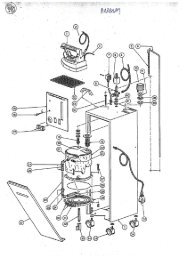
BAG FEED-IN DEVICE NOS. G29905, GR29905, GB29905 AND <strong>GBR29905</strong>ALIMENTADOR DE SACOS Nos. G29905, GR29905, GB29905 Y <strong>GBR29905</strong>Ref. No. Part No. Description Descripción Amt. req.Ref. Nº Parte Nº Cant.Req.1 - 101 G29905G, Bag Feed-in Device Alimentador de sacos 1GB29905G 220-240/380-415 V, 3 phase, 50 Hz 220-240/380-415 V, Trifásico, 50 Hz 1Speed: 11-23 m/min., I = 30:1 Velocidad: 11-23 m/min., I = 30:1243-277/420-480 V, 3 phase, 60 Hz 243-277/420-480 V, Trifásico, 60 HzSpeed: 13-27 m/min., I = 30:1 Velocidad: 13-27 m/min., I = 30:1GR29905G, Bag Feed-in Device Alimentador de sacos 1<strong>GBR29905</strong>G 220-240/380-415 V, 3 phase, 50 Hz 220-240/380-415 V, Trifásico, 50 Hz 1Speed: 9-16 m/min., I = 38:1 Velocidad: 9-16 m/min., I = 38:1243-277/420-480 V, 3 phase, 60 Hz 243-277/420-480 V, Trifásico, 60 HzSpeed: 10-19 m/min., I = 38:1 Velocidad: 10-19 m/min., I = 38:1G29905X1, Bag Feed-in Device Alimentador de sacos 1GB29905X1 220/440 V, 3 phase, 60 Hz 220/440 V, Trifásico, 60 Hz 1Speed: 13-27 m/min., I = 30:1 Velocidad: 13-27 m/min., I = 30:1<strong>GBR29905</strong>X1 Bag Feed-in Device Alimentador de sacos 1220/440 V, 3 phase, 60 Hz 220/440 V, Trifásico, 60 HzSpeed: 10-19 m/min., I = 38:1 Velocidad:10-19 m/min., I = 38:11 99631 Cover Cubierta 12 95413 Screw Tornillo 33 95951 Washer Arandela 34 99644 Pulley without Hub Polea sin cubo 25 95412 Screw Tornillo 46 99644A Pulley with Hub Polea con cubo 27 95205 Set Screw Tornillo de sujeción 28 999-107 V-Belt Correa en V 19 999-109 Lip Seal Empaquetadura 110 99627 Support Soporte 111 95408 Screw Tornillo 412 95675 Stud Perno 213 95251 Nut Tuerca 214 96900 Washer Arandela 215 96201 Spring Washer Arandela muelle 216 95251 Nut Tuerca 217 997G405 Gear Motor Motor de engranaje 1220-240/380-415 V, 3 phase, 50 Hz 220-240/380-415 V, Trifásico, 50 Hz243-277/420-480 V, 3 phase, 60 Hz 243-277/420-480 V, Trifásico, 60 HzI = 30:1 I = 30:1997G401 Gear Motor Motor de engranaje 1220-240/380-415 V, 3 phase, 50 Hz 220-240/380-415 V, Trifásico, 50 Hz243-277/420-480 V, 3 phase, 60 Hz 243-277/420-480 V, Trifásico, 60 HzI = 38:1 I = 38:1997X1-405 Gear Motor Motor de engranaje 1220/440 V, 3 phase, 60 Hz 220/440 V, Trifásico, 60 HzI = 30:1 I = 30:1997X1-401 Gear Motor Motor de engranaje 1220/440 V, 3 phase, 60 Hz 220/440 V, Trifásico, 60 HzI = 38:1 I = 38:118 95145 Screw for Motor Tornillo del motor 419 998-337AK Reduction Reductor 120 998-313C Cable Screwing Cable atornillado 121 G 21233CJ Cable Cable 122 998-313J Cable Screwing Cable atornillado 123 998-257D Plug Enchufe 124 998-256D Socket Zócalo 125 95154V Screw Tornillo 426 96100 Lockwasher Arandela de presión 427 95257V Nut Tuerca 428 99642 Gear Engranaje 229 95205 Set Screw Tornillo de sujeción 130 999-78B Plug Tapón 231 999-21 Lubricating Nipple Tubo de lubricación 132 999-22 Lubricating Mark Punto de lubricación 133 99639D Spacer Sleeve Distanciador 2Ref. Nos. 34 – 80 see page 17 Refs. Nos. 34 – 80 ver página 1715
BAG FEED-IN DEVICE NOS. G29905, GR29905, GB29905 AND <strong>GBR29905</strong>ALIMENTADOR DE SACOS Nos. G29905, GR29905, GB29905 Y <strong>GBR29905</strong>Ref. No. Part No. Description Descripción Amt. req.Ref. Nº Parte Nº Cant.Req.34 99640 Flange Bushing Assembly, upper Conj. Cojinete con pestaña, superior 135 999-106 Ball Bearing Cojinete de bolas 235A 999-106R Ball Bearing, stainless steel Cojinete de bolas, Acero inoxidable 236 99640D Spacer Sleeve Distanciador 137 99640A Flange Bushing Assembly, upper Conj. Cojinete con pestaña, superior 138 999-106 Ball Bearing Cojinete de bolas 138A 999-106E Ball Bearing, stainless steel Cojinete de bolas, Acero inoxidable 139 95412 Screw Tornillo 440 99641A Upper Shaft, driven Eje superior, engranaje 141 99643 Cardan Joint Junta del cardán 142 95205 Set Screw Tornillo de sujeción 243 99641B Lower Shaft, driven Eje inferior, engranaje 144 99641 Driving Shaft Eje impulsor 145 99628A Gear Box Caja de engranajes 146 99629 Bushing Bocina 247 99589A Stud Perno 248 95001 Hex. Head Screw Tornillo cabeza hexagonal 149 95251 Nut Tuerca 150 97010 Spring Resorte 251 95205 Set Screw for 99589A Tornillo de sujeción para 99589A 252 95051 Hex. Head Screw Tornillo cabeza hexagonal 153 95250 Nut Tuerca 154 99640B Flange Bushing Assembly, lower Conj. Cojinete con pestaña, inferior 255 999-106 Ball Bearing Cojinete de bolas 155A 999-106R Ball Bearing, stainless steel Cojinete de bolas, Acero inoxidable 156 95412 Screw Tornillo 457 99630 Swivel Arm Brazo oscilante 158 99634HB Carrier Plate, rear Caja cadenas, posterior 158A 99634HBK Carrier Plate, rear, short version Caja cadenas, posterior, versión corta 159 99634VB Carrier Plate, front Caja cadenas, anterior 159A 99634VBK Carrier Plate, front, short version Caja cadenas, anterior, versión corta 160 99635F Guide Rail Riel guía 261 99590E Bracket Soporte 462 95412 Screw Tornillo 863 HA20A Washer Arandela 864 99635KA Guide Plate, height: 80 mm Plancha guía, altura: 80 mm 264A 99635K Guide Plate, height: 30 mm Plancha guía, altura: 30 mm 265 999-125WA Warning Sign Aviso de precaución 166 95412 Screw Tornillo 467 HA20A Washer Arandela 468 99636 Clamp Sujetador 469 95403 Screw Tornillo 670 999-121A Roller Chain, U-type with rubber Cadena tipo U, con protectores de goma 270A 999-121AA Master Link for 999-121A ,not shown Diente principal para 999-121A, no se 1muestra en el dibujo.70B 999-121AE Roller Chain, stainless steel, U-type Cadena, Acero inoxidable, protectores de 2with rubbergoma70C 999-121AEA Master Link for 999-121AE, notDiente principal para 999-121AE, no se 1shownmuestra en el dibujo.70D 999-121L Roller Chain, L-type with rubber Cadena tipo L, con protectores de goma 270E 999-121LA Master Link for 999-121L, not shown Diente principal para 999-121L, no se 1muestra en el dibujo.70F 999-121LK Roller Chain, short version , L-type Cadena, versión corta, tipo L, con protectores2de gomawith rubber71 95290 Nut Tuerca 472 51244L Washer Arandela 873 99639D Spacer Sleeve Distanciador 474 99639G Sprocket Assembly Conj. Piñón 675 999-106 Ball Bearing Cojinete de bolas 175A 999-106E Ball Bearing, stainless steel Cojinete de bolas, Acero inoxidable 176 99638 Spacer Stud Perno distanciador 477 99632F Chain Guard Protector de la cadena 277A 99632EK Chain Guard, short version Protector de la cadena, versión corta 278 141 Screw Tornillo 879 99635G Chain Guide Guía de las cadenas 480 95403 Screw Tornillo 8Ref. Nos. 81 – 101 see page 19 Refs. Nos. 81 – 101 ver página 1917
BAG FEED-IN DEVICE NOS. G29905, GR29905, GB29905 AND <strong>GBR29905</strong>ALIMENTADOR DE SACOS Nos. G29905, GR29905, GB29905 Y <strong>GBR29905</strong>Ref. No. Part No. Description Descripción Amt. req.Ref. Nº Parte Nº Cant.Req.81 96902 Washer Arandela 882 99639TA Sprocket, 12 teeth Piñón, 12 dientes 283 95205 Set Screw Tornillo de sujeción 184 269 Nut, lefthand thread Tuerca, enrosca a la derecha 285 18 Nut Tuerca 286 51240D Stud for Chain Adjuster Perno para ajustar la cadena 287 99619A Chain Adjuster Fork Tridente para ajustar la cadena 488 99373D Hex. Head Screw Tornillo cabeza hexagonal 289 99639E Washer Arandela 490 95253 Nut Tuerca 291 99627A Bracket for Feed-in Device Soporte alimentador de sacos 192 95022 Hex. Head Screw Tornillo cabeza hexagonal 293 95953 Washer Arandela 294 99627B Bracket for Feed-in Device Soporte alimentador de sacos 195 95251 Nut Tuerca 196 95028A Hex. Head Screw Tornillo cabeza hexagonal 197 21388 Wrench, size 9.5 mm Llave, tamaño 9,5 mm 198 95633B Wrench, size 5/16” x 3/8” Llave, tamaño 5/16 x 3/8 199 95601 Allen Wrench size 4 mm Llave Allen, tamaño 4 mm 1100 95641 Wrench for Belt Drive Llave para correa del alimentador 1101 29926A Pre-Feeler Switch, not shown, Interruptor del pre palpador, no se muestra1see pages 30 and 31 ver páginas 30 y 31CHAIN TENSION ADJUSTER, SPRING LOADEDAJUSTE DE LA TENSION DE LAS CADENAS1 V99619B Chain Tension Adjuster Ajustador de tensión de las cadenas 12 1021U Washer Arandela 13 95578 Nut Tuerca 14 95290 Nut Tuerca 15 99619C Sleeve Manga 16 97020 Spring Resorte 17 99619B Fork Tridente 18 99365BA145 olt Correa 19 95953 Washer Arandela 110 99619D Holder Sujetador 111 96669 Roll Pin Pasador de seguridad 112 95290 Nut Tuerca 113 51244L Washer Arandela 314 99639D Spacer Sleeve Manga distanciadora 115 99638 Spacer Stud Perno distanciador 116 99639G Sprocket Assembly Conj. Piñón 117 999-106 Ball Bearing Cojinete de bolas 119
BAG-TOP FOLD-OVER DEVICE 93051FA*DOBLADILLADOR SUPERIOR 93051FA*Ref. No. Part No. Description Descripción Amt. req.Ref. Nº Parte Nº Cant.Req.1 93051FB1 Sword Espada 12 93051FB2 Bracket Soporte 13 95115 Screw Tornillo 24 96207 Locking Ring Anillo de retención 25 95255 Nut Tuerca 36 93051F1A Connection Conexión 17 95117 Screw Tornillo 18 96207 Locking Ring Anillo de retención 19 93051EB2 Guide Guía 110 95412 Screw Tornillo 411 HA20A Washer Arandela 1012 93051FB3 Deviating Spiral Espiral de desviación 113 93051F3A Bracket Soporte 114 95412 Screw Tornillo 215 95403A Screw Tornillo 216 93051FB7 Guide Guía 117 93051F6 Guide Guía 118 95412B Screw Tornillo 219 93051E4 Bracket Soporte 120 93051E5 Bracket Soporte 121 95403 Screw Tornillo 222 96902 Washer Arandela 2* Extra order and charge item for bag feed-in deviceNos. GB29905 and <strong>GBR29905</strong>.* Piezas tiene que ser ordenadas y pagadas por separadoen los alimentadores de sacos Nos. GB29905 y<strong>GBR29905</strong>.21
BAG FEED-IN, TRIMMING AND TAPING DEVICE NOS. G29910, GR29910, GB29910 AND GBR29910ALIMENTADOR DE SACOS, CORTADOR Y COLOCADOR DE CINTAS Nos. G29910, GR29910, GB29910 Y GBR29910Ref. No. Part No. Description Descripción Amt. req.Ref. Nº Parte Nº Cant.Req.NOTE: Parts which are not illustrated andlisted are the same as for bag feed-indevices shown on pages 14 to 19.NOTA: Las piezas que no aparecen listadas aquí,son las mismas de los alimentadores de sacos mostradosen las páginas 14 a la 19.1 - 49 G29910G, Bag Feed-in Device Alimentador de sacos 1GB29910G 220-240/380-415 V, 3 phase, 50 Hz 220-240/380-415 V, Trifásico, 50 Hz 1Speed: 11-23 m/min., I = 30:1 Velocidad: 11-23 m/min., I = 30:1243-277/420-480 V, 3 phase, 60 Hz 243-277/420-480 V, Trifásico, 60 HzSpeed: 13-27 m/min., I = 30:1 Velocidad: 13-27 m/min., I = 30:1GR29910G, Bag Feed-in Device Alimentador de sacos 1GBR29910G 220-240/380-415 V, 3 phase, 50 Hz 220-240/380-415 V, Trifásico, 50 Hz 1GBR29920G Speed: 9-16 m/min., I = 38:1 Velocidad: 9-16 m/min., I = 38:1243-277/420-480 V, 3 phase, 60 Hz 243-277/420-480 V, Trifásico, 60 HzSpeed: 10-19 m/min., I = 38:1 Velocidad: 10-19 m/min., I = 38:1GB29910X1 Bag Feed-in Device Alimentador de sacos 1220/440 V, 3 phase, 60 Hz 220/440 V, Trifásico, 60HzSpeed: 13-27 m/min., I = 30:1 Velocidad: 13-27 m/min., I = 30:1GBR29910X1 Bag Feed-in Device Alimentador de sacos 1220/440 V, 3 phase, 60 Hz 220/440 V, Trifásico, 60 HzSpeed: 10-19 m/min., I = 38:1 Velocidad: 10-19 m/min., I = 38:11 99532B Stud Perno 22 99642 Gear Engranaje 23 95205 Set Screw Tornillo de sujeción 14 99642D Intermediate Gear Engranaje intermedio 25 99642B Gear Engranaje 26 95205 Set Screw Tornillo de sujeción 17 99639D Spacer Sleeve Distanciador 28 999-106 Ball Bearing Cojinete de bolas 48A 999-106R Ball Bearing, stainless steel Cojinete de bolas, Acero inoxidable 49 999-122 Compensating Ring Aro de compensación 410 95412 Screw Tornillo 611 54274P Washer Arandela 212 95515 Set Screw Tornillo de sujeción 213 99640J Bushing Bocina 214 999-106X Thrust Ball Bearing Cojinete de bolas 215 96163A Supporting Ring Arandela de soporte 216 96258 Retaining Ring Anillo retenedor 117 96172 Retaining Ring Anillo retenedor 118 99584AC Chip Chute Conductor del chip 118A 99590E Bracket Soporte 119 95413 Screw Tornillo 420 HA20B Washer Arandela 421 99641J Knifeshaft Eje de la cuchilla 222 96378 Woodruff Key Cuña 223 99641JA Set Collar Anilla 124 95500 Set Screw Tornillo de sujeción 125 97010B Spring Resorte 126 99670KA Knife Cuchilla 227 95500 Setscrew for Lower Knife Tornillo de sujeción cuchilla inferior 128 99641JB Set Collar Anilla 129 95500 Set Screw Tornillo de sujeción 130 99632C Hand Guard, right Protector de mano, derecho 131 95412 Screw Tornillo 232 95955 Washer Arandela 233 99632DA Hand Guard, left Protector de mano, izquierdo 134 95412 Screw Tornillo 235 95955 Washer Arandela 236 999-125WB Warning Sign Hand Aviso de precaución, manos 237 999-125WA Warning Sign Aviso de precaución 123
BAG FEED-IN, TRIMMING AND TAPING DEVICE NOS. G29910, GR29910, GB29910 AND GBR29910ALIMENTADOR DE SACOS, CORTADOR Y COLOCADOR DE CINTAS Nos. G29910, GR29910, GB29910 YGBR29910BAG FEED-IN AND TRIMMING DEVICE NO. GBR29920ALIMENTADOR DE SACOS Y CORTADOR DE CINTA No. GBR29920Ref. No. Part No. Description Descripción Amt. req.Ref. Nº Parte Nº Cant.Req.38 95054 Hex. Head Screw Tornillo cabeza hexagonal 239 1021U Washer Arandela 240 A8852BA Bracket Soporte 141 A8852BB Adjustable Bracket Soporte, ajustable 142 95051 Screw Tornillo 643 96902 Washer Arandela 644 A8852BC Folder Bracket Soporte del dobladillador 145 99628A Gear Box Caja del engranaje 146 99629 Bushing Bocina 247 A8852A50 Paper Tape Folder for 50 mm wide tape Dobladillador para cintas de 50 mm de ancho 1A8852A55 Paper Tape Folder for 55 mm widetapeDobladillador para cintas de 55 mm de ancho 1A8852A60 Paper Tape Folder for 60 mm wide Dobladillador para cintas de 60 mm de ancho 1A8852A63tapePaper Tape Folder for 63 mm wide tape Dobladillador para cintas de 63 mm de ancho 1A8852A65 Paper Tape Folder for 65 mm wide tape Dobladillador para cintas de 65 mm de ancho 1tapeA8852A70 Paper Tape Folder for 70 mm wide Dobladillador para cintas de 70 mm de ancho 148 95620tapeScrew Driver Destornillador 149 29927P Blower Device, not shown,see pages 34 and 35Soplador, no se muestra en el dibujo,ver páginas 34 y 351A Cemented in the lower key slot.B Cemented in the upper key slot.C The smaller inner diameter of thrust ball bearingin the rear bushing must be up when assembling.D The bigger inner diameter of thrust ball bearingin the front bushing must be up when assembling.A Cementadas en la ranura de la caja inferior.B Cementadas en la ranura de la caja superior.C El minimo diametro interno del Cojinete de bolas en la bocinaposterior, debe ser aumentado cuando se monte.D El diametro maximo interno del Cojinete de bolas en la bocinaanterior, debe ser aumentado cuando se monte.25
BAG FEED-IN, TRIMMING AND FOLD OVER DEVICE NOS. GB29915 AND GBR29915ALIMENTADOR DE SACOS, CORTADOR Y COLOCADOR DE CINTAS Nos. GB29915 Y GBR29915Ref. No. Part No. Description Descripción Amt. req.Ref. Nº Parte Nº Cant.Req.NOTE: Parts which are not illustrated and NOTA: Las piezas que no aparecen listadas aquí, sonlisted are the same as for bag feed-in las mismas de los alimentadores de sacos mostradosdevices shown on pages 14 to 19.en las páginas 14 a la 19..1 - 55 GB29915G Bag Feed-in Device Alimentador de sacos 1220-240/380-415 V, 3 phase, 50Hz 220-240/380-415 V, Trifásico, 50 HzSpeed: 11-23 m/min., I = 30:1 Velocidad: 11-23 m/min., I = 30:1243-277/420-480 V, 3 phase, 60Hz 243-277/420-480 V, Trifásico, 60 HzSpeed: 13-27 m/min., I = 30:1 Velocidad: 13-27 m/min., I = 30:1GBR29915G Bag Feed-in Device Alimentador de sacos 1220-240/380-415 V, 3 phase, 50Hz 220-240/380-415 V, Trifásico, 50 HzSpeed: 9-16 m/min., I = 38:1 Velocidad: 9-16 m/min., I = 38:1243-277/420-480 V, 3 phase, 60Hz 243-277/420-480 V, Trifásico, 60 HzSpeed: 10-19 m/min., I = 38:1 Velocidad: 10-19 m/min., I = 38:1GB29915X1 Bag Feed-in Device Alimentador de sacos 1220/440 V, 3 phase, 60 Hz 220/440 V, Trifásico, 60 HzSpeed: 13-27 m/min., I = 30:1 Velocidad: 13-27 m/min., I = 30:1GBR29915X1 Bag Feed-in Device Alimentador de sacos 1220/440 V, 3 phase, 60 Hz 220/440 V, Trifásico, 60 HzSpeed: 10-19 m/min., I = 38:1 Velocidad: 10-19 m/min., I = 38:11 99532B Stud Perno 22 99642 Gear Engranaje 23 95205 Set Screw Tornillo de sujeción 14 99642D Intermediate Gear Engranaje intermedio 25 99642B Gear Engranaje 26 95205 Set Screw Tornillo de sujeción 17 99639DB Spacer Sleeve Distanciador 28 999-106 Ball Bearing Cojinete de bolas 48A 999-106R Ball Bearing, stainless steel Cojinete de bolas, Acero inoxidable 49 999-122 Compensating Ring Aro de compensación 410 95412 Screw Tornillo 611 54274P Washer Arandela 212 95515 Set Screw Tornillo de sujeción 213 99640BJ Bushing Bocina 214 96253 Retaining Ring Anillo retenedor 215 96172 Retaining Ring Anillo retenedor 216 99584AB Chip Chute with Washer Plate Conductor del chip con arandela 117 95051 Hex. Head Screw Tornillo cabeza hexagonal 218 96902 Washer Arandela 219 99628A Gear Box Caja del engranaje 120 99629 Bushing Bocina 221 99641BJ Knifeshaft Eje de la cuchilla 222 99670KA Knife Cuchilla 223 95500 Set Screw Tornillo de sujeción 224 99632C Hand Guard, right Protector de mano, derecho 125 95412 Screw Tornillo 226 95955 Washer Arandela 227 99632DA Hand Guard, left Protector de mano, izquierdo 128 95412 Screw Tornillo 229 95955 Washer Arandela 230 999-125WB Warning Sign Hand Aviso de precaución, manos 231 999-125WA Warning Sign Aviso de precaución 132-53 93051FB Bag-Top Fold-Over Device Dobladillador superior 132 93051FB1 Sword Espada 133 93051FB2 Bracket Soporte 134 95115 Screw Tornillo 235 96207 Locking Ring Anillo de retención 236 95255 Nut Tuerca 337 93051F1A Connection Conexión 138 95117 Screw Tornillo 139 96207 Locking Ring Anillo de retención 140 93051EB2 Guide Guía 141 95412 Screw Tornillo 442 HA20A Washer Arandela 1043 93051FB3B Deviating Spiral Espiral de desviación 127
BAG FEED-IN, TRIMMING AND FOLD OVER DEVICE NOS. GB29915 AND GBR29915SACKZUFÜHR-, BESCHNEIDE- UND UMLEGEEINRICHTUNGEN NR. GB29915 UND GBR29915Ref. No. Part No. Description Descripción Amt. req.Ref. Nº Parte Nº Cant.Req.44 93051F3A Bracket Soporte 145 95412 Screw Tornillo 246 95403A Screw Tornillo 247 93051FB7 Guide Guía 148 93051F6 Guide Guía 149 95412B Screw Tornillo 250 93051E4 Bracket Soporte 151 93051E5 Bracket Soporte 152 95403 Screw Tornillo 253 96902 Washer Arandela 254 95620 Screw Driver Destornillador 155 29927P Blower Device, not shown,see pages 30 and 31Soplador, no se muestra en el dibujo,ver Páginas 30 y 31129
PRE-FEELER SWITCHINTERRUPTOR DEL PRE PALPADORRef. No.Pos. Nr.Part No.Parte NºDescription Descripción Amt. Req.Cant.Req.1-20 29926A Pre-Feeler Switch Parts Kit Conj. Partes interruptor pre1palpador1 90233BE Cable and Plug Assembly Cable y enchufe, completo 12 1240008 Cable 1,5 m (5 ft.) long Cable 1,5 m largo 13 998-226A-5 Cable Sleeve Protector del cable 14 998-226A-1 Plug Housing Carcasa del enchufe 15 998-226A-2 Contact Insert for Plug Contactos del enchufe 16 998-226A-3 Pin Contact Puntas de contacto 27 998-226A-4 Sealing plug Sellador del enchufe 58 998-228 Protecting Cap Tapa protectora 19 998-227A-2 Contact Insert for Receptacle Contactos del receptaculo 110 998-227A-3 Socket Contact Contactos del soporte 311 998-226A-4 Sealing Plug Sellador del enchufe 412 998-227A-1 Receptacle Housing Carcasa del receptaculo 113 998-358C Cable Clamp Sujetador del cable 214 99590M Bracket for Feeler Switch Soporte del interruptor del1palpador15 95413 Screw Tornillo 216 HA20B Washer Arandela 217 998-526M20 Cable Screwing Conector de los cables 118 998-480 Feeler Switch Interruptor del palpador 119 95156V Screw Tornillo 220 96100 Lockwasher Arandel 221* 998-230 Nut Tuerca 1* Extra order and charge item.* Pieza debe ser ordenada y pagada por separado.31
LIGHT BARRIERBARRERA LIGERARef. No.Pos. Nr.Part No.Parte NºDescription Descripción Amt. Req.Cant.Req.1 29926EO Light Barrier Assembly Conj. Barrera ligera 12 998-364RP Repeller Repelente 13 95257V Nut Tuerca 24 96100 Lock Washer Arandela de seguridad 55 998-364PB Light Barrier with Plug Barrera ligera con enchufe 16 95176Z Screw Tornillo 37 95403C Screw Tornillo 28 96102 Lock Washer Arandela de seguridad 29 99720LA Holder Sujetador 110 99720LB Guide Plate Placa guía 111 95146 Screw Tornillo 212 99720L Holder Soporte 113 998-358C Cable Clamp, not shown Sujetador del cable, no se muestra. 314 998-493 Clamp, not shown Cable, no se muestra. 115 998-496D Marking Strip, not shown Linea de marca, no se muestra. 116 90234DA Socket Assembly for Light Barrier Conj. De enchufe para barrera1with plug, not shownligera, no se muestra.17 95412 Screw Tornillo 418 HA20A Washer Arandela 419 99636 Clamp Sujetador 433
The blower device can be mountedsupplementary also on former bag feed-indevices. For this, two tap holes M6 have tobe drilled on the rear of the gear box of thebag feed-in device, see sketch.Die Blasvorrichtung kann auch nachträglichan ältere Alimentador de sacoen montiertwerden. Dazu müssen auf der Rückseite desRäderkastens der Alimentador de saco zweiGewindebohrungen M6 angebracht werden,ver Skizze.34
BLOWER DEVICE FOR TRIMMINGSSOPLADOR DE COSTURA SOBRANTERef. No.Pos. Nr.Part No.Parte NºDescription Descripción Amt. Req.Cant.Req.1-16 29927P Blower Device for G29910, GR29910,GB29910, GBR29910, GB29915,GBR29915 and GBR29920Soplador para G29910, GR29910,GB29910, GBR29910, GB29915,GBR29915 y GBR299201 95255 Nut Tuerca 22 95955 Washer Arandela 23 95951 Washer Arandela 24 95057 Hex. Head Screw Tornillo cabeza hexagonal 25 A9893RA-1 Bracket Soporte 16 999-255F Whisker Valve Válvula de segura 17 95422 Screw Tornillo 28 999-149 Gasket Empaquetadura 39 999-249B Hollow Bolt with Throttle Valve Perno hueco de la válvula reguladora 110 999-248 Ring Type Nipple Arandela de seguridad 111 999-217 Swivel Fitting Inserto articulado 112 95412 Screw Tornillo 113 HA20A Washer Arandela 114 A9893RA Blower Tube Tubo del soplador 115* 1314002 PE-Tube, 0.36 m long Tubo PE, 0,36 m largo 116* 1314001 PE-Tube, 0.8 m long Tubo PE, 0,8 m largo 117 999-163A T-Fitting, not shown Inserto en forma de T, no se muestra. 118 999-199B Coupling, not shown Acoplamiento, no se muestra. 11* Please indicate Part-No., description and required lengthwhen ordering.* Favor indicar número de parte, descripción y largorequerido cuando ordene.35
NUMERICAL INDEX OF PARTSINDICE NUMERICO DE PARTESPart No.Parte NºPagePáginaPart No.Parte NºPagePágina18141269213889500195022950519505495057951159511795145951469520595250952519525395255952909540395408954129541395422955009551595578956019562095641956759595195953961009610296172962019620796253962589637896669969009690297010970209962799629996309963119171919171917, 25, 27253521, 2721, 27153315, 27, 29, 23, 271715, 27, 191921, 27, 3517, 1917, 21, 291515, 17, 21, 23, 27, 29, 33, 3515, 23, 313523, 2723, 27191925, 29191515, 3519, 23, 27, 3515, 31, 333323, 271521, 27272323191519, 21, 25, 27, 2917191517, 25, 271715996369963899640996419964299643996441240008131400113140021021U29926A29926EO29927P51240D51244L54274P90233BE90234DA93051 E493051 E593051EB293051F1A93051F3A93051F693051FB93051FB193051FB293051FB393051FB3B93051FB795028A95154V95156V95176Z95257V95403A95403C95412B95633B96163A97010B99365BA14599373D99532B99584AB99584AC99589A99590E17, 3317, 19171715, 23, 27171531353519, 2519, 313325, 29, 351917, 1923, 27313321, 2921, 2921, 2721, 2721, 2921, 292721, 2721, 27212721, 291915313315, 3321, 293321, 29192323191923, 2727231717, 2336
NUMERICAL INDEX OF PARTSINDICE NUMERICO DE PARTESPart No.Parte NºPagePáginaPart No.Parte NºPagePágina99590M99619A99619B99619C99619D99627A99627B99628A99632C99632DA99632EK99632F99634HB99634HBK99634VB99634VBK99635F99635G99635K99635KA99639D99639DB99639E99639G99639TA99640A99640B99640BJ99640D99640J99641A99641B99641BJ99641J99641JA99641JB99642B99642D99644A99670KA99720L99720LA99720LB997G401997G405997X1-401997X1-405998-226A-1998-226A-2998-226A-33119191919191917, 25, 2723, 2723, 271717171717171717171715, 17, 19, 23271917, 1919171727172317172723232323, 2723, 271523, 2733333315151515313131998-226A-4998-226A-4998-226A-5998-227A-1998-227A-2998-227A-3998-228998-230998-256D998-257D998-313C998-313J998-337AK998-358C998-364PB998-364RP998-480998-493998-496D998-526M20999-106999-106E999-106R999-106X999-107999-109999-121A999-121AA999-121AE999-121AEA999-121L999-121LA999-121LK999-122999-125WA999-125WB999-149999-163A999-199B999-21999-217999-22999-248999-249B999-255F999-78BA8852A50A8852A55A8852A60A8852A633131313131313131151515151531, 3333333133333117, 19, 23, 271717, 23, 272315151717171717171723, 2717, 23, 2723, 27353535153515353535152525252537
NUMERICAL INDEX OF PARTSINDICE NUMERICO DE PARTESPart No.Parte NºPagePáginaPart No.Parte NºPagePáginaA8852A65A8852A70A8852BAA8852BBA8852BCA9893RAA9893RA-1G 21233CJG29905G,G29905X1,G29910G,GB29905GGB29905X1GB29910GGB29910X1GB29915GGB29915X1<strong>GBR29905</strong>G<strong>GBR29905</strong>X1GBR29910GGBR29910X1GBR29915GGBR29915X1GBR29920GGR29905G,GR29910G,HA20AHA20BV99619B252525252535351515152315152323272715152323272723152317, 21, 27, 33, 3523, 311938
UNION SPECIAL GmbHRaiffeisenstraße 3D-71696 MöglingenGermanyMANUFACTURER'S DECLARATIONIn accordance with the EC Machinery Directive 98/37/EC, Annex IIBWe herewith declare that the bag feed-in device described asPart No. 29900must be incorporated into a sewing unit or sewing system and that it must not be putinto service until the sewing unit or sewing system into which this bag feed-in device isto be incorporated has been declared in conformity with the provisions of the EC MachineryDirective.Applied harmonized standards: in particular:EN 292-1, EN 292-2, ISO / DIS 10821, EN 60204-31.DECLARACION DEL FABRICANTEDe acuerdo con la directiva de maquinaria de la Comunidad Economica Europea98/37/EG, Anexo IIBDECLARAMOS que el Alimentador de sacos descrito comoParte Nº 29900Solo puede ser utilizado cuando haya sido incorporado a una unidad de maquina decoser o a un sistema de coser previamente declarado apto de conformidad con lasprovisiones de la directiva de maquinaria de la Comunidad Economica Europea.Estandares armonizados aplicados, en particular:EN 292-1, EN 292-2, ISO / DIS 10821, EN 60204-31.UNION SPECIAL GmbHArno BriegelManaging Director / Director PrincipalII