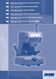
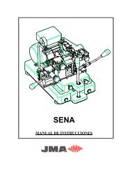
3Copying Duplicado keys dewith “Block A”2.4Technical details3.14 sided clampEnglishThe main technical details are set out below:Motor: Single phase 220V, 50Hz, 0.18Kw,1500 rpm, 1.6 Amp.“Block A” Milling tool: Extra high-speed steel ø80 x 16 x5 mm.“Block B” Milling tool: Extra high-speed steel ø80 x 16 x 1.4 mm(three cuts).Speed: 530 rpm.“Block A” Clamp: Four positions.“Block B” Clamp: Three positions.Displacement: With sliding and turning shaft.Lighting: Halogen lamp.Dimensions: Width = 590 mm, Depth = 470 mm, Height = 260 mm.Weight: 50 Kg.2.5Components and functional parts2.5.1 Acc<strong>es</strong>sori<strong>es</strong> See figure 41 Wrench of 18.2 Cutting-depth adjustment plate.3 Shims for adjusting the tip stop.4 Shim with rec<strong>es</strong>s for duplicating cruciform keys.5 Cutting-depth adjustment plate, block “B”.6 Sided adjustment piec<strong>es</strong>, block “B”.7 Set of Allen keys (2.5, 3, 4, 5, 6).8 Rod for changing milling tool (ø7x140).2.5.2 Electrical circuit See figure 5The main components of electrical and electronic circuitare as follows:123456789101112220V current intake. 50Hz.Connector stripTransformer for 220V lamp. – 12v.Lamp switch.Halogen lamp.General switch.Pilot lamp.Block “A” microswitch.Block “B” microswitch.Condenser.Motor.Security relay.The clamp is d<strong>es</strong>igned to secure a family of differentkeys on each side. The figure shows the possibiliti<strong>es</strong> forcopying on each side of the clamp.a) Copying keys with a support on the back:Side 1: Keys with normal blade.Side 2: Keys with narrow blade.b) Copying by securing the key with the guide (profile).Side 3 and Side 4. See figure 6c) Copying by securing the key with the guide (NEIMAN type)See figure 73.2Control and lateral adjustment “Block A”Place the two adjustment keys (1) in the clamps. The head ofthe adjustment key butts against the inside stop of side 1 or 2of the clamp.Now tighten the clamps.Move the clamps with the adjustment keys (1) towards the copyingindex (I) and the milling tool (F) so that the adjustmentkeys are in the correct position with the copying index and themilling tool. This can be done by pr<strong>es</strong>sing the button (P) andmoving the carriage gently over the copying index (I) and themilling tool (F). See figure 2Should the notch<strong>es</strong> in the adjustment keys not coincide with thecopying index and with the milling tool, proceed as follows:Loosen the (T) screws in the support, and knock the side of theblock so that the copying index support mov<strong>es</strong> to the right orleft in order to make this coincide with the notch in the corr<strong>es</strong>pondingadjustment key.The distance is now perfectly adjusted and the copying index andthe milling tool coincide with the r<strong>es</strong>pective rec<strong>es</strong>s<strong>es</strong> in the adjustmentkeys. Now, tighten to lock the screws (T) in the support.See figure 83.3Control and adjustment of the cuttingdepth of “Block A”Disconnect the machine’s power cable from mains electricity.Place the two adjustment keys (1) in the clamps. The head of theadjustment key butts against the inside stop of side 1 or 2 of theclamp.Move the clamps with the adjustment keys (1) towards the copyingindex (I) and the milling tool (F) so that the adjustment keys r<strong>es</strong>tagainst the copying index and the milling tool. The machine carriageis released by pr<strong>es</strong>sing the button (P).Turn the milling tool with your hand. When the milling tool rubs slightlyagainst the adjustment keys, the machine is correctly adjusted.If the milling tool turns freely, without rubbing, this indicat<strong>es</strong> thatthe milling tool is moving behind the tracer and is not cuttingsufficiently. On the other hand, if the milling tool is locked in theadjustment key, the shows that the milling tool is moving aheadof the tracer and is cutting exc<strong>es</strong>sively. If one of th<strong>es</strong>e two incidentsoccurs, proceed as follows:Loosen the set screw (J) that locks the copying index (I) and turningthe micrometric screw (H). See figure No. 3.Bring the copying index forward or back until the milling tool turnsand rubs the adjustment key very slightly. Next, tighten the set screw(J) of the copying index. The machine is now ready to operate.See figure 910
4The copyingkeys “Block B”:3.4Key copying operation4.13 sided clampInsert the original key in the left-hand clamp, keeping adistance of from 2 to 3 mm between it and the edge of theclamp. See figure 4Tighten the clamp, keeping the back of the key correctlysupported on the base of the clamp.Insert the uncut key in the right-hand clamp and beforetaking the clamp, lift the gauge (C) and align the two keys,making sure that the two calibre indic<strong>es</strong> r<strong>es</strong>t firmly on theupper stops of both keys. Lastly, tighten the clamps.Both the original key and the uncut key for copying mustbe inserted from the left of the r<strong>es</strong>pective clamps.Start the machine and by holding the carriage by meansof the handle (M), move the keys towards the copyingindex (I) and the milling tool (F), by pr<strong>es</strong>sing the button(P). Gauge (C) withdraws automatically when the carriagemov<strong>es</strong> towards the copying index and the milling tool.Remember that the machine works from left to right.R<strong>es</strong>t the original key against the copying index and beginto work, moving the carriage from right to left, usingthe arm (B). Make sure that the pr<strong>es</strong>sure exerted on thecopying index is the one required by the spring built intothe carriage shaft.When the key has been copied, returned the carriage tothe original position. Now, withdraw the keys by releasingthe clamps.If, when copying, burrs are left on the copied key, th<strong>es</strong>emay be eliminated with the brush provided for this purpose.See figure 103.4.1 Copying keys with narrow blad<strong>es</strong>. Side 2 ofthe clamp.(padlocks/letterbox<strong>es</strong>)For copying this kind of key, and so that the milling tool reach<strong>es</strong>the maximum cutting depth, use side 2 of the clamp as this allowsyou to cut more deeply when copying.3.4.2 Copying keys without stopsInsert the two shims (2) (see figure no. 6) in the verticalgroov<strong>es</strong> (R) of each clamp, in accordance with the length ofthe key to be copied.R<strong>es</strong>t the tips of the keys against the shims (2). The keysare adjusted in this way. Now, tighten the clamps. Befor<strong>es</strong>tarting to copy the key, it is advisable to remove the shims.See figure 113.4.3 Copying the cruciform key. Side 1 of the clampThis type of key must be inserted in the clamps from left to right.Place the shims (5) (see figure no. 7) with the opening or rec<strong>es</strong>sdownwards, in one or other groove (R), according to the lengthof the key to be copied.The serrations of the key are cut in three positions, by turning andlocking the stop of the key on the shim on each occasion (5).See figure 12The clamp is d<strong>es</strong>igned to secure a family of different keyson each side. Let’s take a look at the different sid<strong>es</strong>:Side 1:Side for copying lever tumbler keys with one blade ortwin blade.Side 2:Copying frontal keys.Side 3:Copying the special key FO-4P. In the clamp there is a 45ºgroove that allows this special key to be copied.For more details, see the chapters on key copying.4.2Control and lateral adjustment “Block B”Place the two adjustment piec<strong>es</strong> (6).Move the clamps towards the copying index (I) and the millingtool (F) so that the adjustment keys r<strong>es</strong>t on the copying indexand the milling tool. The machine carriage is released by looseningthe handle (B).Should the adjustment keys not coincide with the copying indexand with the milling tool, proceed as follows:Loosen the two screws (T) of the support and, with a small plastichammer, tap this slightly to the right or left so that it coincid<strong>es</strong>with the adjustment key. See figure No. 2.Now, the distance is perfectly adjusted and the copying indexand the milling tool coincide with the r<strong>es</strong>pective adjustmentpiec<strong>es</strong>. Now, tighten to lock the support screws (T).See figure 134.3 Control and adjustment of the cuttingdepth of “Block B”Place the two adjustment bars (7) on the clamps, as indicatedin the d<strong>es</strong>ign.Move the clamps with the adjustment bars (7) towards the copyingindex (I) and the milling tool (F) so that the adjustmentrods r<strong>es</strong>t against the copying index and the milling tool. Themachine carriage is released by loosening the handle (B).Turn the milling tool with your hand. If the milling tool rubsagainst the adjustment rods slightly, the machine is correctlyadjusted.If the milling tool turns freely, without rubbing, this indicat<strong>es</strong>that it do<strong>es</strong> not cut at a sufficient depth. On the other hand, ifthe milling tool jams in the adjustment rod, this shows that thecut is too deep.If one of th<strong>es</strong>e two incidents occurs, proceed as follows:Release the set screw (L) that locks the copying index (I) andturn the micrometric screw (H). See figure no. 3.Bring the copying index forward or backward until the millingtool turns and rubs against the adjustment rod very slightly.Now, tighten the screw (L) of the copying index. The machineis now in perfect working order.English11