MULTÃMETRO DIGITAL DIGITAL MULTIMETER - Ega Master
MULTÃMETRO DIGITAL DIGITAL MULTIMETER - Ega Master
MULTÃMETRO DIGITAL DIGITAL MULTIMETER - Ega Master

Create successful ePaper yourself
Turn your PDF publications into a flip-book with our unique Google optimized e-Paper software.
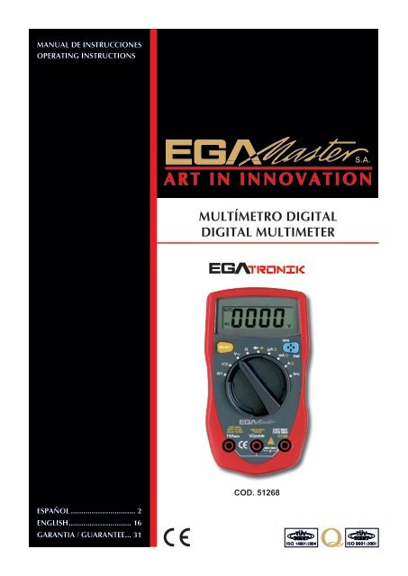
INFORMACIÓN GENERALEste manual de instrucciones contiene información sobre seguridad y precaución. Por favor leaatentamente la información relevante y observe todas las advertencias y notas de manera estricta.¡Advertencia!Para evitar descargas eléctricas o daños personales, lea con atención antes dela utilización del medidor, la “Información relativa a la seguridad” y “Reglaspara una operación segura”El Multímetro Digital Modelo COD. 51268 (en adelante “El Medidor) de 3 3/4 dígitos conoperaciones estables, estructura moderna y es un instrumento de medición altamente fiable. Elmedidor puede medir tensiones AC/DC, resistencia, transistor hFE, diodo y continuidad. Es unaherramienta ideal para mantenimiento.DESEMBALAJEAbra el paquete y saque el medidor. Compruebe cuidadosamente los siguientes elementos paravisualizar cualquier pérdida o parte dañada:Artículo Descripción Cantidad1 Manual de Instrucciones 12 Cable de prueba 1 par3 Funda 14 Batería 1,5V (AAA), instalada 2En el caso de encontrar alguna pérdida o daño, por favor póngase en contacto con sudistribuidor inmediatamente.INFORMACION DE SEGURIDADEste Medidor cumple con los estándares IEC61010: grado de contaminación 2, categoría desobretensión (CAT I 600V, CAT II 300V) y doble aislamiento.CAT.I: Nivel de señal, equipamiento especial o partes de equipamiento, telecomunicación,electrónica, etc.., con menores sobrevoltajes transitorios que sobrevoltajes CAT.II.CAT. II: Nivel local, dispositivo, EQUIPO PORTÁTIL, etc., con menores sobretensionestransitorias que CAT III.Utilice este Medidor sólo como se especifica en este manual, de lo contrario la protecciónprovista en el instrumento podría verse afectada.En este manual, una advertencia identifica condiciones y acciones que representan riesgos parael usuario, o posibles daños al medidor o al equipo bajo prueba.Una nota identifica la información a la que el usuario debe prestar atención.Los símbolos eléctricos internacionales usados en el medidor y en el manual de instruccionesson explicados en la página 4.3
REGLAS PARA UN FUNCIONAMIENTO SEGURO¡Advertencia!Antes del uso del medidor inspeccione la carcasa. No use el medidor si ésta estádañada o la carcasa (o parte de ella) está retirada. Busque roturas o posibles faltasde plástico.- Preste atención al aislamiento alrededor de los conectores.- Inspeccione los cables de prueba por posibles daños en el aislante o partesmetálicas expuestas. Verifique la continuidad de los cables de prueba. Reemplacelos cables dañados por unos de idéntico número de modelo o especificacioneseléctricas, antes del uso del medidor.- No aplique más del ratio de tensión marcado en el medidor, entre los terminaleso entre cualquier terminal y la toma de tierra. Si el valor a ser medido esdesconocido, use la posición de máxima medida y reduzca el rango poco a pocohasta que la lectura obtenida sea satisfactoria.- La posición de la ruleta debería estar situada en la posición correcta y sin ningúncambio durante la medición evitando daños en el Medidor.- Cuando el Medidor trabaje con una tensión eficaz por encima de 60V en DC o42V rms en AC, se deberá tomar especial cuidado al peligro de posibles descargaseléctricas.- No utilice o almacene el Medidor en un ambiente de alta temperatura, humedad,explosivo, inflamable y fuertes campos magnéticos. La capacidad del Medidorpuede deteriorarse después de humedecerse.- Cuando utilice los cables de prueba, mantenga sus dedos tras el protector.- Desconecte la energía del circuito y descargue todos los condensadores de altatensión antes de testear la resistencia, continuidad y diodo.- Reemplace la batería tan pronto como el indicador de batería aparezca. Con unabatería baja, el Medidor puede producir falsas lecturas que pueden conducir adescargas eléctricas o daños personales.- Retire los cables de prueba del Medidor y apáguelo antes de abrir la tapa.- Al reparar el Medidor, use solamente el mismo número de modelo o repuestosde idénticas especificaciones eléctricas.- El circuito interno del Medidor no debe ser alterado para evitar posibles daños alMedidor y cualquier accidente.- La superficie del Medidor debe ser limpiada con un trapo suave y un detergentesuave. No deben usarse disolventes ni abrasivos para prevenir la corrosión de lasuperficie, daño o accidente.- El Medidor el apropiado para uso en interior.- Apague el medidor cuando no esté en uso y extraiga la batería cuando no seausada durante un largo periodo de tiempo.- Compruebe constantemente la batería ya que puede tener pérdidas cuandohaya sido usado durante algún tiempo, remplace la batería tan pronto como laspérdidas aparezcan.SIMBOLOS ELECTRICOS INTERNACIONALESAC o DCCorriente ACCorriente DCToma de tierraDoble aislamiento4
Deficiencia de la bateríaDiodoFusiblePrueba de continuidadAdvertencia. Consultar manual de instruccionesConforme con los estándares de la Unión EuropeaESTRUCTURA DEL MEDIDOR(figura 1)1. Pantalla LCD2. Botón SELECT3. Conmutador giratorio4. Terminal de entrada COM5. Terminal de entrada 10ª6. Otro Terminal de entrada7. Terminal de entrada transistorFUNCIÓN DE LOS BOTONESBotón SELECTSeleccione para medición de corriente AC y DC, prueba de continuidad y prueba de diodo.Se emitirá un sonido cuando se pase de una función a otra. Presione este botón para activar elMedidor cuando esté en modo “Sleep”.5
PANTALLA LCD (vea figura 2)(figura 2)OPERACIÓN DE MEDIDAA. Medición de voltaje DC (vea figura 3)¡Advertencia!Para evitar daños personales o daños al Medidor provocados por descargaseléctricas, por favor no intente medir tensiones superiores a 500V aunque laslecturas puedan ser obtenidasLos rangos de tensión DC son: 400.0mV, 4.000V, 40.00V, 400.0V y 500V1. Inserte el cable de prueba rojo en el terminal VΩmA y el cable de prueba negro en el terminalCOM.2. Gire el conmutador hasta V .3. Conecte los cables de prueba en el objeto a ser medido.El valor será mostrado en la pantalla.negrorojo(figura 3)Nota:- La medición DCV es autoajustable. El Medidor tiene una impedancia de entrada deaproximadamente 10MΩ.Este efecto de carga puede provocar errores de medición en circuitos dealta impedancia. Si la impedancia del circuito es menor o igual que 10KΩ, el error es despreciable(0.1% o menos).- Cuando la medición de tensión DC haya sido completada, desconecte la conexión entre loscables de prueba y el circuito bajo prueba.6
B. Medición de tensión AC (vea figura 3)¡Advertencia!Para evitar daños personales o daños al Medidor provocados por descargaseléctricas, por favor no intente medir tensiones superiores a 500V aunque laslecturas puedan ser obtenidas.Los rangos de tensión DC son: 4.000V, 40.00V, 400.0V y 500V1. Inserte el cable de prueba rojo en el terminal VΩmA y el cable de prueba negro en el terminal COM.2. Gire el conmutador hasta V .3. Conecte los cables de prueba en el objeto a ser medido.El valor será mostrado en la pantalla.Nota:- La medición DCV es autoajustable. El Medidor tiene una impedancia de entrada deaproximadamente 10MΩ. Este efecto de carga puede provocar errores de medición en circuitos dealta impedancia. Si la impedancia del circuito es menor o igual que 10KΩ, el error es despreciable(0.1% o menos).- Cuando la medición de tensión DC haya sido completada, desconecte la conexión entre loscables de prueba y el circuito bajo prueba.C. Medición de corriente (vea figura 4)¡Advertencia!Nunca intente medir la corriente de un circuito cuando la tensión entre losterminales y tierra sea mayor que 60V. Si durante la medición un fusible sequema, el Medidor puede ser dañado o el operario puede resultar herido. Use losterminales apropiados, función y rango para la medición. Cuando los cables deprueba estén conectados a los terminales, no los cruce en ningún circuito.Para medir la corriente, siga las siguientes indicaciones:1. Desconecte la energía del circuito. Descargue todos los capacitores de alto voltaje.2. Inserte el cable de prueba rojo en el terminal VΩmA o 10A y el cable negro de prueba en elterminal COM.3. Gire el conmutador hasta una posición apropiada de medición en posición A . MediciónDC aparece por defecto o presione SELECT para seleccionar modo de medición DC.4. Corte la corriente de la parte a ser probada. Conecte el cable de prueba rojo a lado máspositivo del corte y el cable de prueba negro al lado más negativo.5. Conecte la energía del circuito. El valor de la medición será mostrado en la pantalla.negrorojo(figura 4)7
Nota:- Si el valor de la corriente es desconocido, use la posición de medición máxima (10ª) y reduzcapoco a poco el rango hasta obtener una lectura satisfactoria.- Cuando la medición de tensión DC haya sido completada, desconecte la conexión entre loscables de prueba y el circuito bajo prueba.D. AC Medición de corriente (vea figura 4)¡Advertencia!Nunca intente medir la corriente de un circuito cuando la tensión entre losterminales y tierra sea mayor que 60V. Si durante la medición un fusible sequema, el Medidor puede ser dañado o el operario puede resultar herido. Use losterminales apropiados, función y rango para la medición. Cuando los cables deprueba estén conectados a los terminales, no los cruce en ningún circuito.1. Desconecte la energía del circuito. Descargue todos los capacitores de alto voltaje.2. Gire el conmutador hasta la posición adecuada, presione SELECT para cambiar de DC a AC.3. Inserte el cable de prueba rojo en el terminal VΩmA o 10A y el cable de prueba negro en elterminal COM.4. Gire el conmutador a una posición de medición apropiada en posición A .5. Corte la corriente de la parte a ser probada. Conecte el cable de prueba rojo a lado máspositivo del corte y el cable de prueba negro al lado más negativo.6. Conecte la energía del circuito. El valor de la medición será mostrado en la pantalla.E. Medición de resistencia (vea figura 5)¡Advertencia!Para evitar daños al Medidor o a los instrumentos bajo prueba, desconecte laenergía del circuito y descargue todos los capacitores de alto voltaje antes derealizar la medición.Los rangos de Ω son: 400.0Ω, 4.000kΩ, 40.00kΩ, 400.0kΩ, 4.000MΩ y 40.00MΩ,1. Inserte el cable de prueba rojo en el terminal VΩmA y el cable de prueba negro en el terminalCOM.2. Gire el conmutador hasta Ω.3. Conecte los cables con el objeto a ser medido. El valor se mostrará en la pantalla.negrorojo(figura 5)8
Nota:- Los cables de prueba pueden añadir un error de 0.1Ω a 0.3Ω a la medición de resistencia.Para obtener lecturas precisas en bajas resistencias, rango de 200Ω, cortocircuite la entrada delos terminales de antemano y memorice la lectura obtenida (llamada esta lectura como X). (X) ellas resistencia adicional del cable de prueba. Por lo tanto use la ecuación: valor de la medida deresistencia (Y)-(X)= precisión de la lectura de resistencia.- Para medición de alta resistencia (>1MΩ), es normal que tarde varios segundos hasta obteneruna lectura estable.- Cuando la medición de resistencia haya sido completado, desconecte la conexión entre loscables de prueba y el circuito bajo prueba.F. Prueba de diodo y continuidad (vea figura 6)Prueba de diodos¡Advertencia!Para evitar daños al Medidor o a los instrumentos bajo prueba, desconecte laenergía del circuito y descargue todos los capacitores de alto voltaje antes derealizar la medición.Use la prueba de diodo para comprobar diodos, transistores, y otros instrumentossemiconductores. La prueba de diodo envía una corriente a través de la unión semiconductor,midiendo la caída de tensión a través de una unión.Una buena unión de siliceo cae entre 0.5V y 0.8V.negrorojo(figura 6)Para probar un diodo fuera de un circuito, conecte el Medidor de la siguiente manera:1. Inserte el cable de prueba rojo en el terminal VΩmA y el cable de prueba negro en el terminalCOM.2. Gire el conmutador hasta como defecto marca medición de diodo o presioneSELECT para seleccionar modo de medición de diodo.3. Para las lecturas de caída de tensión en cualquier componente semiconductor, coloque elcable de prueba rojo en el ánodo del componente y el cable de prueba negro en el cátodo delcomponente.El valor medido será mostrado en la pantalla.9
Nota- En un circuito, un diodo en buen estado debe producir una lectura de caída de tensión de0,5 V a 0,8 V, sin embargo, la lectura inversa de caída de tensión puede variar en función de laresistencia de otras vías entre las puntas de las sonda.- Conecte los cables de prueba en los terminales adecuados como se indica arriba para evitarmuestras erróneas. La pantalla mostrará “OL” indicando circuito abierto por error de conexión. Launidad del diodo es Voltio (V), mostrando la relación positiva del valor de la caída de tensión.- Cuando la prueba de diodo haya sido completada, desconecte la conexión entre los cables deprueba y el circuito bajo prueba.Prueba de continuidadPara realizar la prueba de continuidad, conecte el Medidor de la siguiente manera:1. Inserte el cable de prueba rojo en el terminal VΩmA y el cable de prueba negro en el terminalCOM.2. Gire el conmutador hasta .3. Presione SELECT para seleccionar modo de medición de continuidad.4. Conecte los cables de prueba con el objeto a ser medido. Se emitirá un sonido si la resistenciadel circuito bajo prueba es inferior a 100Ω.G. Medición de transistor hFE¡Advertencia!Para evitar daños al medidor o a otros instrumentos bajo prueba, nointroduzca corrientes superiores a 60V DC o 30V AC.1. Compruebe que el transistor es tipo PNP o NPN.2. Conecte el transistor a medir en las correspondientes clavijas.3. La pantalla LCD muestra valor de referencia hFE.(figura 7)SLEEP MODEPara preservar la vida de la batería, el Medidor se apaga automáticamente si no gira elconmutador o presiona algún botón durante 15 minutos. El Medidor puede ser activadopresionando SELECT o girando el conmutador giratorio.10
ESPECIFICACIONES GENERALES- Máxima tensión entre los terminales y toma de tierra: 500V rms.- Protección fusible para terminal de entrada VΩmA: 500mA, 250V tipo rápido, Ø5x20 mm- Terminal 10A: sin fusible.- Rango: Auto rango- Máximo mostrado: 3999.- Velocidad de medición: actualiza 3 veces por segundo.- Temperatura:Operando: 0ºC~40ºC (32ºF~104 ºF).Almacenado : -10ºC~50ºC (14ºF~122ºF).- Humedad relativa: 75% @ 0ºC - 30ºC; 50% @ 31 - 40ºC.- Altitud: Operando: 2000 m.Almacenado: 10000 m.- Batería: 2 baterías 1.5V AAA.- Deficiencia de la batería: Se muestra: .- Lectura negativa: Se muestra : “-“.- Sobrecarga: Muestra “0L”.- Dimensiones (HxWxL): 130 x 73.5 x 35mm.- Peso: Aprox. 156g (batería incluida).- Conformidades de seguridad: IEC61010 CAT I 600V, CAT II 300V sobrevoltaje y dobleaislamiento estándar.- Certificado:Precisión: (lectura a% + b digitos), garantía de 1 año.Temperatura de operación: 23ºC -5ºCHumedad relativa:
Notas:- Impedancia de entrada: aprox. 10MΩ.- Valor efectivo mostrado de la onda senoidal (valor respuesta medio)Respuesta frecuencia: 40Hz-400Hz.C. Corriente DCRango Resolución Precisión Protección sobrecarga400µA 0.1µA±(1%+2)4000µA 1µA40mA 10µA400mA 100µA4A1mA10A 10mA±(1.2%+2)500mA/250V tipo fusiblerápido Ø5x20mm±(1.5%+5) Sin fusibleNotas:- En rango 10ª: Para mediciones continuas de 10 segundos e intervalo no inferior a 15 minutos.- Impedancia de entrada: aprox.10MΩ.- Medición de caída de tensión: Rango completo a 400mV.D. Corriente ACRango Resolución Precisión Protección sobrecarga400µA 0.1µA±(1.5%+5)4000µA 1µA40mA 10µA400mA 100µA4A1mA10A 10mA±(2%+5)500mA/250V tipo fusiblerápido Ø5x20mm±(2.5%+5) Sin fusibleNota:- En rango 10ª: Para mediciones continuas de 10 segundos e intervalo no inferior a 15 minutos.- Impedancia de entrada: aprox. 10MΩ.- Medición de caída de tensión: Rango completo a 400mV.E. ResistenciaRango Resolución Precisión Protección sobrecarga400Ω 0.1Ω ±(1.2%+2)4kΩ1Ω40kΩ10Ω±(1%+2)400kΩ 100Ω250V DC o AC4MΩ 1kΩ ±(1.2%+2)40MΩ 10kΩ ±(1.5%+2)12
F. Medición de diodos y continuidadRango Resolución Nota Protección sobrecarga1mVMuestra lectura aproximada decaída de tensión250V DC o AC0.1Ω Se emite un sonido a
3. Retire el destornillador de la tapa de la base del Medidor.4. Retire la batería de su compartimento.5. Sustituya la batería por una nueva (1.5V AAA).6. Vuelva a colocar la tapa y el tornillo.TORNILLO(figura 8)C. Sustitución del fusible (vea figura 8)¡Advertencia!Para evitar descargas eléctricas o arcos de explosión, o daños personaleso al Medidor, use sólo fusibles específicos y de acuerdo con el siguienteprocedimiento.Para sustituir el fusible del Medidor:1. Desconecte la conexión entre los cables de prueba y el circuito bajo prueba, y retire loscables de prueba de los terminales del medidor.2. Ponga en posición OFF el conmutador para el apagado del Medidor.3. Retire el destornillador de la tapa de la base del Medidor.4. Retire el fusible aflojándolo suavemente, y sacándolo de su compartimento.5. Instale SÓLO fusibles del tipo y especificaciones adecuadas como se marca y asegúrese queel fusible está correctamente colocado en su compartimento.Fusible: 1:500mA 250V, tipo rápido, Ø5x20mm.6. Vuelva a colocar la tapa de la base y el tornillo.La sustitución del fusible se realiza raramente. La quema de un fusible es resultado de un malfuncionamiento.14
NOTAS¡IMPORTANTE!El fabricante no se responsabiliza de los daños o mal funcionamiento del aparato en caso de queno se use correctamente o se haya utilizado para trabajos para los que no está diseñado.Según la directiva sobre residuos eléctricos de aparatos eléctricos y electrónicos(RAEE), éstos deberán recogerse y tratarse por separado. Si en el futuro tiene que deshacerse deeste producto, no se deshaga de él junto con la basura doméstica. Póngase en contacto con sudistribuidor para proceder a su reciclaje de manera gratuita cuando sea posible.GARANTÍAEl fabricante garantiza al comprador de este aparato la garantía total durante 12 meses de laspiezas con defectos de fabricación.Esta garantía no cubre aquellas piezas que por su uso normal tienen un desgaste.Nota: para obtener la validez de la garantía, es absolutamente imprescindible que complete yremita al fabricante el documento de “CERTIFICADO DE GARANTIA”, dentro de los siete dias apartir de la fecha de compra.15
ENGLISHTABLE OF CONTENTSOverview ........................................................................................................ 17Unpacking Inspection....................................................................................................... 17Safety Information ........................................................................................................ 17Rules For Safe Operation.................................................................................................. 18International Electrical Symbols........................................................................................ 19The Meter structure ........................................................................................................ 19Functional Buttons ........................................................................................................ 20LCD Display ........................................................................................................ 20Measurement Operation................................................................................................... 20A. DC Voltage Measurement............................................................................................ 20B. AC Voltage Measurement............................................................................................. 21C. DC Current Measurement............................................................................................ 21D. AC Current Measurement............................................................................................ 22E. Resistance Measurement............................................................................................... 22F. Diode and Continuity Test............................................................................................ 23G. Transistor hFE Measurement........................................................................................ 24Sleep Mode ........................................................................................................ 25General Specifications...................................................................................................... 25A. DC Voltage ........................................................................................................ 26B. AC Voltage ........................................................................................................ 26C. DC Current ........................................................................................................ 26D. AC Current ........................................................................................................ 27E. Resistance ........................................................................................................ 27F. Diodes and Continuity.................................................................................................. 27G. Transistor hFE Test....................................................................................................... 27Maintenance ........................................................................................................ 28A. General Service ........................................................................................................ 28B. Replacing the Battery................................................................................................... 28C. Replacing the Fuses...................................................................................................... 2916
OVERVIEWThis Operating Manual covers information on safety and cautions. Please read the relevantinformation carefully and observe all the Warnings and Notes strictly.Warning!To avoid electric shock or personal injury, read the “Safety Information” and“Rules for Safety Operation” carefully before using the Meter.The Model COD. 51268 Multimeter is a 3 3/4 digits with steady operations, fashionable designand highly reliable hand-held measuring instrument. The Meter can measure AC/DC voltage, AC/DC Current, Resistance, Transistor hFE, Diode and Continuity. It is an ideal tool for maintenance.UNPACKING INSPECTIONOpen the package case and take out the Meter. Check the following items carefully to see anymissing or damaged part:Item Description Qty1 English Operating Manual 1 piece2 Test Lead 1 pair3 Holster 1 piece4 1.5V Battery (AAA) (installed) 2 pieceIn the event you find any missing or damage, please contact your dealer immediately.SAFETY INFORMATIONThis Meter complies with the standards IEC61010: in pollution degree 2, overvoltage category(CAT I 600V, CAT II 300V) and double insulation.CAT. I: Signal level, special equipment or parts of equipment, telecommunication, electronic,etc., with smaller transient overvoltages than overvoltages CAT. II.CAT. II: Local level, appliance, PORTABLE EQUIPMENT etc., with smaller transient overvoltagesthan CAT. IIIUse the Meter only as specified in this operating manual, otherwise the protection provided bythe Meter may be impaired.In this manual, a Warning identifies conditions and actions that pose hazards to the user, or maydamage the Meter or the equipment under test. A Note identifies the information that user shouldpay attention on.International electrical symbols used on the Meter and in this Operating Manual are explainedon page 19.17
INTERNATIONAL ELECTRICAL SYMBOLSAC or DCAC CurrentDC CurrentGroundingDouble InsulatedDeficiency of Built-In BatteryDiodeFuseContinuity TestWarning. Refer to the Operating ManualConforms to Standards of European UnionTHE METER STRUCTURE (figure 1)(figure 1)1) LCD Display2) SELECT Button3) Rotary Switch4) COM Input Terminal5) 10A Input Terminal6) Other Input Terminal7) Transistor Input Terminal19
FUNCTIONAL BUTTONSSELECT buttonSelecting for DC and AC current measurement, Continuity Test and Diode Test. Thebuzzer sounds when switching from one function to the other.Press this button toactivate the Meter when it is under Sleep Mode.LCD DISPLAY (see figure 2)(figure 2)MEASUREMENT OPERATIONA. DC Voltage Measurement (see figure 3)Warning!To avoid harms to you or damages to the Meterfrom electric shock, please do not attempt tomeasure voltages higher than 500V althoughreadings may be obtained.The DC Voltage ranges are : 400.0mV, 4.000V, 40.00V, 400.0V and 500V1. Insert the red test lead into the VΩmA terminal and the black test lead into the COM terminal.2. Set the rotary switch to V range.3. Connect the test leads across with the object being measured.The measured value shows on the display.(figure 3)20
Note:- DCV Measurement is autoranging, the Meter has an input impedance of approx. 10MΩ. Thisloading effect can cause measurement errors in high impedance circuits. If the circuit impedance isless than or equal to 10kΩ, the error is negligible (0.1% or less).- When DC voltage measurement has been completed, disconnect the connection between thetesting leads and the circuit under test.B. AC Voltage Measurement (see figure 3)Warning!To avoid harms to you or damages to the Meter from electric shock, pleasedo not attempt to measure voltages higher than 500V although readings maybe obtained.The AC voltage ranges are : 4.000V, 40.00V, 400.0V and 500V1. Insert the red test lead into the VΩmA terminal and the black test lead into the COM terminal.2. Set the rotary switch to V range.3. Connect the test leads across with the object being measured.The measured value shows on the display.Note:- DCV Measurement is autoranging, the Meter has an input impedance of approx. 10MΩ. Thisloading effect can cause measurement errors in high impedance circuits. If the circuit impedance isless than or equal to 10kΩ, the error is negligible (0.1% or less).- When DC voltage measurement has been completed, disconnect the connection between thetesting leads and the circuit under test.C. DC Current Measurement (see figure 4)Warning!Never attempt an in-circuit current measurementwhere the voltage between terminals and groundis greater than 60V . If the fuse burns out duringmeasurement, the Meter may be damaged or theoperator himself may be hurt. Use proper terminals,function, and range for the measurement. Whenthe testing leads are connected to the currentterminals, do not parallel them across any circuit.To measure current, do the following:1. Turn off power to the circuit. Discharge all highvoltage capacitors.2. Insert the red test lead into the VΩmA or 10A terminal and the black test lead into the COMterminal.3. Set the rotary switch to an appropriate measurement position in A range. DC measurementis default or press SELECT button to select DC measurement mode.4. Break the current path to be tested. Connect the red test lead to the more positive side of thebreak and the black test lead to the more negative side of the break.5. Turn on power to the circuit. The measured value shows on the display.21
(figure 4)Note:- If the value of current to be measured is unknown, use the maximum measurement position(10A) and reduce the range step by step until a satisfactory reading is obtained.- When current measurement has been completed, disconnect the connection between thetesting leads and the circuit under test.D. AC Current Measurement (see figure 4)Warning!Never attempt an in-circuit current measurement where the open-circuit voltagebetween the circuit and ground is greater than 500V.If the fuse burns out during measurement, the Meter may be damaged or theoperator himself may be hurt. Use proper terminals function, and range for themeasurement. When the testing leads are connected to the current terminals,do not parallel them across any circuit.1. Turn off power to the circuit. Discharge all high-voltage capacitors.2. Turn the rotary switch to suitable range, press SELECT to change from DC to ACmeasurement.3. Insert the red test lead into the VΩmA or 10A terminal and the black test leadinto the COM terminal.4. Set the rotary switch to an appropriate measurement position in A range.5. Break the current path to be tested. Connect the red test lead to the more positiveside of the break and the black test lead to the more negative side of the break.6. Turn on power to the circuit.The measured value shows on the display.E. Resistance Measurement (see figure 5)Warning!To avoid damages to the Meter or to the devices under test, disconnect circuitpower and discharge all the high-voltage capacitors before measuringresistance.22
The Ω ranges are : 400.0Ω, 4.000kΩ, 40.00kΩ, 400.0kΩ, 4.000MΩ, and 40.00MΩ,1. Insert the red test lead into the VΩmA terminal and the black test lead into the COM terminal.2. Set the rotary switch to the Ω range.3. Connect the test leads across with the object being measured. The measured value shows onthe display.(figure 5)Note:- The test leads can add 0.1Ω to 0.3Ω of error to resistance measurement. To obtain precisionreadings in low-resistance measurement, that is the range of 200Ω, short-circuit the input terminalsbeforehand and record the reading obtained (called this reading as X). (X) Is the additionalresistance from the test lead. Then use the equation: measured resistance value (Y) - (X) = precisionreadings of resistance.- For high-resistance measurement (>1MΩ), it is normal taking several seconds to obtain a stablereading.- When resistance measurement has been completed, disconnect the connection between thetesting leads and the circuit under test.F. Diode and Continuity Test (see figure 6)Testing DiodesWarning!To avoid damages to the Meter or to the devices under test, disconnect circuitpower and discharge all the high-voltage capacitors before diodes.Use the diode test to check diodes, transistors, and other semiconductor devices. The diode testsends a current through the semiconductor junction, and then measures the voltage drop acrossthe junction.A good silicon junction drops between 0.5V and 0.8V.23
(figure 6)To test a diode out of a circuit, connect the Meter as follows:1. Insert the red test lead into the VΩmA terminal and the black test lead into the COM terminal.2. Set the rotary switch to Diode measurement is default or press SELECT button toselect diode measurement mode.3. For forward voltage drop readings on any semiconductor component, place the red test leadon the component’s anode and place the black test lead on the component’s cathode.The measured value shows on the display.Note- In a circuit, a good diode should still produce a forward voltage drop reading of 0.5V to 0.8V;however, the reverse voltage drop reading can vary depending on the resistance of other pathwaysbetween the probe tips.- Connect the test leads to the proper terminals as said above to avoid error display. The LCDwill display “OL” indicating open-circuit for wrong connection. The unit of diode is Volt (V),displaying the positive-connection voltage-drop value.- When diode testing has been completed, disconnect the connection between the testing leadsand the circuit under test.Testing for ContinuityTo test for continuity, connect the Meter as below:1. Insert the red test lead into the VΩmA terminal and the black test lead into the COM terminal.2. Set the rotary switch to .3. Press SELECT button to select continuity measurement mode.4. Connect the test leads across with the object being measured.The buzzer sounds if the resistance of a circuit under test is less than 100Ω.G. Transistor hFE Measurement (see figure 7)Warning!To avoid damages to the Meter or to the devices under test, do not input anycurrent over 60V DC or 30V AC.1. Check that the transistor is PNP or NPN type.2. Connect the transistor to be measured to the corresponding jacks.3. LCD display hFE reference value.24
(figure 7)SLEEP MODETo preserve battery life, the Meter automatically turns off if you do not turn the rotary switch orpress any button for around 15 minutes. The Meter can be activated by pressing the SELECT buttonor turning the rotary switch.GENERAL SPECIFICATIONS- Maximum Voltage between any Terminals and Grounding: 500V rms.- Fused Protection for VΩmA Input Terminal: 500mA, 250V fast type, Ø5x20 mm- 10A Terminal: Un-fused.- Range: Auto ranging- Maximum Display: Display: 3999.- Measurement Speed: Updates 3 times / second.- Temperature:Operating: 0ºC~40ºC (32ºF~104 ºF).Storage: -10ºC~50ºC (14ºF~122ºF).- Relative Humidity: 75% @ 0ºC - 30ºC; 50% @ 31 - 40ºC.- Altitude: Operating: 2000 m.Storage: 10000 m.- Battery Type: Two piece of 1.5V AAA Battery.- Battery Deficiency: Display: .- Negative reading: Display: “-“.- Overloading: Display: “0L”.- Dimensions (HxWxL): 130 x 73.5 x 35mm.- Weight: Approx. 156g (battery included).- Safety/Compliances: IEC61010 CAT I 600V, CAT II 300V overvoltage and doubleinsulation standard.- Certification:Accuracy: (a% reading + b digits), guarantee for 1 year.Operating temperature: 23ºC -5ºC.Relative humidity:
D. AC CurrentRange Resolution Accuracy Overload Protection400µA 0.1µA±(1.5%+5)4000µA 1µA40mA 10µA400mA 100µA4A1mA10A 10mA±(2%+5)500mA/250V fast typefuse Ø5x20mm±(2.5%+5) Un-fusedRemark:- At 10A Range: For continuous measurement 10 seconds and interval not less than 15 minutes.- Input impedance: approx. 10MΩ.- Measurement voltage drop: Full range at 400mV.E. ResistanceRange Resolution Accuracy Overload Protection400Ω 0.1Ω ±(1.2%+2)4kΩ1Ω40kΩ10Ω±(1%+2)400kΩ 100Ω250V DC or AC4MΩ 1kΩ ±(1.2%+2)40MΩ 10kΩ ±(1.5%+2)F. Diodes and Continuity MeasurementRange Resolution Remark Overload Protection1mVDisplays approximate forwardvoltage drop reading250V DC or AC0.1Ω Buzzer beeps at
MAINTENANCEThis section provides basic maintenance information including battery and fuse replacementinstruction.Warning!Do not attempt to repair or service your Meter unless you are qualified to doso and have the relevant calibration, performance test, and service information.To avoid electrical shock or damage to the Meter, do not get water inside thecase.A. General Service- Periodically wipe the case with a damp cloth and mild detergent. Do not use abrasives orsolvents.- To clean the terminals with cotton bar with detergent, as dirt or moisture in the terminals canaffect readings.- Turn the Meter to OFF position when it is not in use and take out the battery when not usingfor a long time.- Do not store the Meter in a place of humidity, high temperature, explosive, inflammable andstrong magnetic field.B. Replacing the Battery (see figure 8)Warning!To avoid false readings, which could lead topossible electric shock or personal injury,replace the battery as soon as the batteryindicator “ ”appears.To replace the battery:1. Disconnect the connection between the testing leads and the circuit under test, and removethe testing leads away from the input terminals of the Meter.2. Turn the Meter to OFF position.3. Remove the screw from case bottom, and separate the case bottom from the case top.4. Remove the battery from the battery compartment.5. Replace the battery with a new 1.5V AAA battery.6. Rejoin the case bottom and case top, and reinstall the screw.(figure 8)28
C. Replacing the Fuses (see figure 8)Warning!To avoid electrical shock or arc blast, or personal injury or damage to the Meter,use specified fuses ONLY in accordance with the following procedure.To replace the Meter’s fuse:1. Disconnect the connection between the testing leads and the circuit under test, and removethe testing leads away from the input terminals of the Meter.2. Turn the Meter to OFF position.3. Remove the screws from case bottom, and separate the case bottom from the case top.4. Remove the fuse by gently prying one end loose, and then take out the fuse from its bracket.5. Install ONLY replacement fuses with the identical type and specification as follows and makesure the fuse is fixed firmly in the bracket.Fuse 1:500mA 250 V, fast type, Ø5x20mm.6. Rejoin the case bottom and case top, and reinstall the screw.Replacement of the fuses is seldom required. Burning of a fuse always results from improperoperation.NOTESIMPORTANT!The maker will not take responsibility for damage or malfunction as a result of the device beingincorrectly used or, applied for a purpose for whith it was not intended.According to Waste Electrical and Electronic Equipment directive (WEEE), these ones mustbe collected and arranged separately. If you have to throw them out, please, do not use the usualrubbish. Please, contact your distributor for free recycling.GUARANTEEThe maker guarantees to the device owner 12 months against any manufacture defect.This guarantee do not cover the parts wich are consumables.Note: to apply the guarantee its necesary to send the “GUARANTEE CERTIFICATE” duly filledwithin one week after purchased the machine to the maker.29
CERTIFICADO DE GARANTIAGUARANTEE CERTIFICATECERTIFICAT DE GARANTIEARTICULO / ITEM / ARTICLE:.....................................................................................................................Nº DE SERIE / SERIE Nº / Nº SERIE:............................................................................................................DISTRIBUIDOR / DISTRIBUTOR / DISTRIBUTEUR:....................................................................................PAIS / COUNTRY / PAYS:..............................................................................TEL.:....................................FECHA DE VENTA / SALE DATE / DATE VENTE:.........................................................................................NOMBRE DEL COMPRADOR / BUYER NAME / NOM DE L’ACHETEUR:...................................................TEL. COMPRADOR / BUYER TEL. / TEL. DE L’ACHETEUR:.........................................................................EGA MASTER GARANTIZA AL COMPRADOR DE ESTA MAQUINA LA GARANTIA TOTAL (DURANTE 12 MESES), DE LAS PIEZAS CON DEFECTOS DE FABRICACION. ESTAGARANTIA NO CUBRE AQUELLAS PIEZAS QUE POR SU USO NORMAL TIENEN UN DESGASTE. PARA OBTENER LA VALIDEZ DE LA GARANTIA , ES ABSOLUTAMENTEIMPRESCINDIBLE QUE COMPLETE Y REMITA ESTE DOCUMENTO A EGA MASTER , DENTRO DE LOS SIETE DIAS A PARTIR DE LA FECHA DE COMPRA.EGA MASTER GUARANTEES TO THE BUYER OF THIS MACHINE THE TOTAL WARRANTY (DURING 12 MONTHS), OF THE PIECES WITH MANUFACTURING FAULTS.THIS GUARANTEE DOES NOT COVER THOSE PIECES WORN OUT DUE TO A NORMAL USE. IN ORDER TO OBTAIN THE VALIDITY OF THIS WARRANTY , IT ISABSOLUTELY NECESSARY TO FULFILL THIS DOCUMENT AND RESEND IT TO EGA MASTER WITHIN 7 DAYS FROM SALE DATE.EGA MASTER GARANTIE A L’ACHETEUR DE CETTE MACHINE LA GARANTIE TOTALE (PENDANT 12 MOIS) DES PIECES AVEC DEFAUTS DE FABRICATION. CETTE GARANTIENE COUVRE PAS LES PIECES QUE PAR UN USAGE NORMAL, SOIENT DETERIOREES. POUR OBTENIR LA VALIDITE DE LA GARANTIE, IL EST ABSOLUMENT IMPERATIFCOMPLETER ET ENVOYER CE DOCUMENT EGA MASTER, DANS UN DELAI DE 7 JOURS A PARTIR DE LA DATE D’ACHAT.SELLO / STAMP / CACHETEJEMPLAR PARA EGA MASTER / COPY FOR EGA MASTER / EXEMPLAIRE POUR EGA MASTERCERTIFICADO DE GARANTIAGUARANTEE CERTIFICATECERTIFICAT DE GARANTIEARTICULO / ITEM / ARTICLE:.....................................................................................................................Nº DE SERIE / SERIE Nº / Nº SERIE:............................................................................................................DISTRIBUIDOR / DISTRIBUTOR / DISTRIBUTEUR:....................................................................................PAIS / COUNTRY / PAYS:..............................................................................TEL.:....................................FECHA DE VENTA / SALE DATE / DATE VENTE:.........................................................................................NOMBRE DEL COMPRADOR / BUYER NAME / NOM DE L’ACHETEUR:...................................................TEL. COMPRADOR / BUYER TEL. / TEL. DE L’ACHETEUR:.........................................................................EGA MASTER GARANTIZA AL COMPRADOR DE ESTA MAQUINA LA GARANTIA TOTAL (DURANTE 12 MESES), DE LAS PIEZAS CON DEFECTOS DE FABRICACION. ESTAGARANTIA NO CUBRE AQUELLAS PIEZAS QUE POR SU USO NORMAL TIENEN UN DESGASTE. PARA OBTENER LA VALIDEZ DE LA GARANTIA , ES ABSOLUTAMENTEIMPRESCINDIBLE QUE COMPLETE Y REMITA ESTE DOCUMENTO A EGA MASTER , DENTRO DE LOS SIETE DIAS A PARTIR DE LA FECHA DE COMPRA.EGA MASTER GUARANTEES TO THE BUYER OF THIS MACHINE THE TOTAL WARRANTY (DURING 12 MONTHS), OF THE PIECES WITH MANUFACTURING FAULTS.THIS GUARANTEE DOES NOT COVER THOSE PIECES WORN OUT DUE TO A NORMAL USE. IN ORDER TO OBTAIN THE VALIDITY OF THIS WARRANTY , IT ISABSOLUTELY NECESSARY TO FULFILL THIS DOCUMENT AND RESEND IT TO EGA MASTER WITHIN 7 DAYS FROM SALE DATE.EGA MASTER GARANTIE A L’ACHETEUR DE CETTE MACHINE LA GARANTIE TOTALE (PENDANT 12 MOIS) DES PIECES AVEC DEFAUTS DE FABRICATION. CETTE GARANTIENE COUVRE PAS LES PIECES QUE PAR UN USAGE NORMAL, SOIENT DETERIOREES. POUR OBTENIR LA VALIDITE DE LA GARANTIE, IL EST ABSOLUMENT IMPERATIFCOMPLETER ET ENVOYER CE DOCUMENT EGA MASTER, DANS UN DELAI DE 7 JOURS A PARTIR DE LA DATE D’ACHAT.SELLO / STAMP / CACHETEJEMPLAR PARA EL CLIENTE / COPY FOR THE CUSTOMER / EXEMPLAIRE POUR LE CLIENT
C/ ZORROLLETA 11, POL. IND. JUNDIZ01015 VITORIA, SPAIN P.O.B. APTDO. 5005TEL. 34 - 945 290 001 FAX. 34 - 945 290 141master@egamaster.comwww.egamaster.com