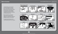
1 2 3 4 7 6 5b 5a - Del Mar Fans and Lighting
1 2 3 4 7 6 5b 5a - Del Mar Fans and Lighting
1 2 3 4 7 6 5b 5a - Del Mar Fans and Lighting
- No tags were found...

Create successful ePaper yourself
Turn your PDF publications into a flip-book with our unique Google optimized e-Paper software.
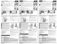
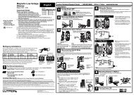
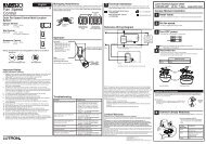
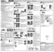
EnglishLutron Technical Support Center 1.800.523.9466 24 hrs / 7 days www.lutron.comP/N 030-1277Single Pole/3-WayQuiet Fan-Speed ControlsAYFSQ-F: 1.5 A 120 V 60 HzDVFSQ-F: 1.5 A 120 V 60 HzDVFSQ-F-HO: 2 A 120 V 60 HzDVSCFSQ-F: 1.5 A 120 V 60 HzDVSCFSQ-F-HO: 2 A 120 V 60 HzLGFSQ-F: 1.5 A 120 V 60 HzLGFSQ-F-HO: 2 A 120 V 60 HzLXFSQ-F: 1.5 A 120 V 60 HzLXFSQ-F-HO: 2 A 120 V 60 HzTGFSQ-F: 1.5 A 120 V 60 HzImportant NotesPlease read before installing.1. CAUTION: To avoid overheating <strong>and</strong> possible damage to other equipment, do not use tocontrol receptacles, fluorescent lighting fixtures, or transformer-supplied appliances.2. Do not use control with a fan <strong>and</strong> light that operate with the same switch.3. When no “grounding means” exist within the wallbox then the NEC® 2008, Article 404.9allows a control without a grounding connection to be installed as a replacement, as longas a plastic, noncombustible wallpate is used. For this type of installation, cap or removethe green ground wire on the control <strong>and</strong> use an appropriate wallplate such as Claro® orFassada® series wallplates by Lutron®.4. Use control with a ceiling paddle fan only. Use only one ceiling paddle fan per control.5. For new installations, wire a test switch before installing the control.6. Set multi-speed fans to their highest setting before installing controls.7. Do not wire controls in a circuit with a GFCI breaker/receptacle.8. Use only one control in a 3-way circuit.9. Install in accordance with all national <strong>and</strong> local electrical codes.10. Clean control with a soft damp cloth only. Do not use any chemical cleaners.Multi-Unit InstallationsWhen combining controls in one wallbox, remove all inner side sections before wiring(see below). Use pliers to bend each side section up <strong>and</strong> down until it breaks off.Reduction of control capacity is not required.Break Side SectionsTechnical AssistanceFor questions concerning the installation or operation of this product, call the Lutron Technical SupportCenter. Please provide exact model number when calling.1.800.523.9466 (U.S.A., Canada, <strong>and</strong> the Caribbean) +1.888.235.2910 (México)+1.610.282.3800 (Other Countries)Fax +1.610.282.6311 Internet: www.lutron.comInside sections areremoved from eachcontrolDo not removeoutside sectionsSide sections are removedfrom both sides of middlecontrolLimited Warranty(Valid only in U.S.A., Canada, Puerto Rico, <strong>and</strong> the Caribbean.)Lutron will, at its option, repair or replace any unit that is defective in materials or manufacture within one year afterpurchase. For warranty service, return unit to place of purchase or mail to Lutron at 7200 Suter Rd., Coopersburg,PA 18036-1299, postage pre-paid.THIS WARRANTY IS IN LIEU OF ALL OTHER EXPRESS WARRANTIES, AND THE IMPLIED WARRANTY OFMERCHANTABILITY IS LIMITED TO ONE YEAR FROM PURCHASE. THIS WARRANTY DOES NOT COVER THECOST OF INSTALLATION, REMOVAL OR REINSTALLATION, OR DAMAGE RESULTING FROM MISUSE, ABUSE,OR DAMAGE FROM IMPROPER WIRING OR INSTALLATION. THIS WARRANTY DOES NOT COVER INCIDENTALOR CONSEQUENTIAL DAMAGES. LUTRON’S LIABILITY ON ANY CLAIM FOR DAMAGES ARISING OUT OF ORIN CONNECTION WITH THE MANUFACTURE, SALE, INSTALLATION, DELIVERY, OR USE OF THE UNIT SHALLNEVER EXCEED THE PURCHASE PRICE OF THE UNIT.This warranty gives you specific legal rights, <strong>and</strong> you may have other rights which vary from state to state. Somestates do not allow the exclusion or limitation of incidental or consequential damages, or limitation on how long animplied warranty may last, so the above limitations may not apply to you.This product may be covered by one or more of the following U.S. patents: 5,191,971; 5,207,317; 5,262,678;5,637,930; 5,359,231; 6,005,308; D558,151, <strong>and</strong> corresponding foreign patents. NEC is a registered trademarkof the National Fire Protection Association, Quincy, Massachusetts. Lutron, Claro, <strong>and</strong> Fassada are registeredtrademarks of Lutron Electronics Co., Inc. © 2010 Lutron Electronics Co., Inc.Lutron Electronics Co., Inc.7200 Suter RoadCoopersburg, PA 18036-1299, U.S.A.Made <strong>and</strong> printed in U.S.A. 2/10 P/N 030-1277 Rev. AInstallationFor installations involving more than one control in a wallbox, refer toMulti-Unit Installations before beginning.1 Turn Power OFF at Circuit Breaker or Remove Fuse.123ONONONOFFOFFOFFRemove Switch Mounting Screws. Pull Switch from Wall.Verify the Application.Ground(Bare Copper or Green Wire)4Single-Pole:Insulated wires connected totwo screws of the same color.See step <strong>5a</strong>.Disconnect Switch Wires.Terminal Screws:Turn screws toloosen.ORGround(Bare Copper orGreen WIre)Tag3-Way:Insulated wires connected to three screws. TAGinsulated wire connected to the different-colored(not green) screw or screw labeled COMMON. Seestep <strong>5b</strong>.ORDifferent-colored screw(Common)Important Note: Your wall switch may have two wires attached to the same screw (see illustrationsbelow for examples). Tape these two wires together before disconnecting. Connect both wiresto the dimmer wire in step 5.One wire in the backwiredhole <strong>and</strong> one tothe screw.WARNING: Shock Hazard. May result in seriousinjury or death. Turn of power at circuit breakerbefore installing the unit.One continuous wire tothe screw.Backwired:Insert screwdriver. Pullwire out.Important Wiring InformationWhen making wire connections, follow the recommended strip lengths <strong>and</strong> combinationsfor the supplied wire connectors. Note: Wire connectors provided are suitable for copperwire only. For aluminum wire, consult an electrician.Small:Twist wireStrip insulation 3/8 in (9.5 mm) for 14 AWG (1.5 mm 2 ) wire.connector tight.Strip insulation 1/2 in (13 mm) for 16 or 18 AWGBe sure no barewire is exposed.(1.0 or 0.75 mm 2 ) wire.Use to join one 14 AWG (1.5 mm 2 ) supply wire withone 16 or 18 AWG (1.0 or 0.75 mm 2 ) control wire.Large:Strip insulation 1/2 in (13 mm) for 10-14 AWG(6-1.5 mm 2 ) wire.Strip insulation 5/8 in (16 mm) for 16 or 18 AWGLarge(1.0 or 0.75 mm 2 ) wire.SmallUse to join one or two 12 or 14 AWG (2.5 or 1.5 mm 2 )supply wires with one 10-18 AWG (6-0.75 mm 2 ) control wire.<strong>5a</strong><strong>5b</strong>67Greenor BareGreenor BareMount <strong>and</strong> Align Control. Install Wallplate.ONONONWire the Control.RedBlackWire the Control.RedBlackStart screws.Turn Power ON.OFFOFFOFFRed/WhiteLive Black Red120 V~60 HzRed/WhiteGreenGroundNeutralRed/WhiteLive Black Red120 V~60 HzRed/WhiteNeutralGreenGroundTagGroundFan3-WaySwitchGroundFanSingle-Pole Circuit:• Connect the green ground wire on thecontrol to the green or bare copperground wire in the wallbox (seeImportant Note 3).• Connect the black wire on the controlto either of the wires removed fromthe switch.• Connect the red wire on the controlto the remaining wire removed fromthe switch.• Using a wire connector, cap off thered/white wire. This wire is not used ina single pole circuit.Or3-Way Circuit:• Connect the green ground wire on thecontrol to the green or bare copperground wire in the wallbox (seeImportant Note 3).• Connect the black wire on the control tothe tagged wire removed from thedifferent-colored (not green) screw onthe switch.• Connect the red wire on the control toeither of the remaining wires removedfrom the switch.• Connect the red/white wire on thecontrol to the remaining wire removedfrom the switch.Align control <strong>and</strong>tighten screws.
Controles Silencioso de Tres Velocidades Para VentiladoresUnipolar/Tres VíasAYFSQ-F: 1,5 A 120 V 60 HzDVFSQ-F: 1,5 A 120 V 60 HzDVFSQ-F-HO: 2 A 120 V 60 HzDVSCFSQ-F: 1,5 A 120 V 60 HzDVSCFSQ-F-HO: 2 A 120 V 60 HzLGFSQ-F: 1,5 A 120 V 60 HzLGFSQ-F-HO: 2 A 120 V 60 HzLXFSQ-F: 1,5 A 120 V 60 HzLXFSQ-F-HO: 2 A 120 V 60 HzTGFSQ-F: 1,5 A 120 V 60 HzNotas ImportantesPor favor, lea antes de instalar.1. PRECAUCIÓN: Para evitar el calentamiento excesivo y posibles daños a otros equipos, no lo use para controlarreceptáculos, instalaciones fluorescentes o aparatos cuya fuente de alimentación incluya un transformador.2. No use el control con un ventilador y una lámpara que funcionen con el mismo interruptor.3. Si en la caja de empotrar no hay acceso a una conexión de tierra, la norma NEC® 2008, Artículo 404.9 permite instalarcomo reemplazo un control sin conexión a tierra, en tanto se utilice una placa de pared de plástico no combustible. Paraeste tipo de instalación, aísle o elimine el conductor verde de tierra del control y utilice una placa de pared adecuada talcomo la ClaroTM o la FassadaTM de Lutron®.4. Use los controles solamente con un ventilador de aspas para techo. Use sólo un ventilador de aspas para techo por cada control.5. En instalaciones nuevas, conecte un interruptor de prueba antes de instalar el control.6. Ajuste los ventiladores de varias velocidades a su velocidad máxima, antes de instalar los controles.7. No cablee controles en un circuito en el cual haya un cortacircuito/receptáculo GFCI.8. En los circuitos de 3 vías use solamente un control.9. Realice la instalación de acuerdo con todos los códigos eléctricos nacionales y locales.10. Limpie la unidad con un paño suave y húmedo únicamente. No use agentes químicos de limpieza.Instalaciones de Unidades MultiplesCu<strong>and</strong>o combine varios controles en una sola caja de empoptrar, quite todas las secciones laterales internas antes de realizarel cableado (vea más abajo). Use unas pinzas para doblar hacia arriba y abajo cada sección lateral hasta que se rompa. No serequiere reducción a de la capacidad del control.Quibre de lasSeccionesLateralesA cada controlse le ha quitadola sección interior.EspañolNo retirelas seccionesexteriores.Al control del mediose la han quitado ambassecciones laterales.Asistencia TécnicaSi tiene preguntas referentes a la instalación o operación de este producto, llame al Centro de Soporte Técnico de Lutron.Por favor suministre el numero exacto del modelo con su llamada.1.800.523.9466 (E.U.A., Canadá, y el Caribe) +1.888.235.2910 (México) +1.610.282.3800 (Otros Países)Fax +1.610.282.6311 Internet: www.lutron.comGarantía Limitada (Válido solamente en los E.U.A., Canadá, Puerto Rico, y el Caribe.)Lutron reparará o reemplazará, a su criterio, cualquier unidad cuyos materiales o fabricación resulten defectuosos en el término de un año despuésde la fecha de compra. Para obtener servicio de garantía, la unidad debe devolverse al lugar de compra o enviar, con franqueo pago, a Lutron, 7200Suter Road, Coopersburg, Pennsylvania 18036-1299.ESTA GARANTÍA SE OFRECE EN LUGAR DE CUALQUIER OTRA GARANTÍA EXPRESA. LA GARANTÍA IMPLÍCITA DE COMERCIABILIDAD ESTÁLIMITADA A UN AÑO, A PARTIR DE LA FECHA DE COMPRA. ESTA GARANTÍA NO CUBRE LOS COSTOS DE INSTALACIÓN, DESMONTAJE NIREINSTALACIÓN. TAMPOCO CUBRE DAÑOS RESULTANTES DE UN USO IMPROPIO O ABUSO, NI DAÑOS DEBIDOS A UNA INSTALACIÓN OCONEXIÓN INCORRECTA. ESTA GARANTÍA NO CUBRE DAÑOS INCIDENTALES NI RESULTANTES. LA OBLIGACIÓN DE LUTRON CON RESPECTO ACUALQUIER RECLAMACIÓN POR DAÑOS RELACIONADOS CON LA FABRICACIÓN, VENTA, INSTALACIÓN, ENTREGA, USO, REPARACIÓN O REEM-PLAZO DE LA UNIDAD, NO SUPERARÁ, EN NINGÚN CASO, EL PRECIO DE COMPRA.Esta garantía otorga derechos legales específicos, pero se podría tener otros derechos, que varían de un estado a otro. Algunos estados no permitenla exclusión o limitación de daños incidentales ni resultantes, ni limitaciones en la duración de una garantía implícita, por lo cual es posible que laslimitaciones mencionadas anteriormente no correspondan en ciertos casos.Este producto está cubierto por uno o más de los siguientes patentes Estounidenses: 5,191,971; 5,207,317; 5,262,678; 5,637,930; 5,359,231;6,005,308; D558,151; y por los patentes extrangeros correspondientes. NEC es una marca comercial registrada de la National Fire ProtectionAssociation, Quincy, Massachussets. Lutron es una marca registrada y Claro y Fassada son marcas registradas de Lutron Electronics Co., Inc.© 2010 Lutron Electronics Co., Inc.Lutron Electronics Co., Inc.7200 Suter RoadCoopersburg, PA 18036-1299, U.S.A.Hecho e impreso en E.U.A. 2/10 P/N 030-1277 Rev. ACentro de Soporte Técnico de Lutron +1.888.235.2910 24 horas / 7 días www.lutron.comInstalaciónPara instalaciones múltiples en una caja de empotrar, antes de empezar vea las instruccionespara unidades múltiples.Apague la corriente en la caja de cortacircuitos o remueva los fusibles.123ONONONOFFOFFOFFRetire la placa de la pared. Saque el interruptor de la pared.Verifique el tipo de interruptor.Tierra(Alambre verde o de cobre desnudo)Unipolar:Alambres revestidos conectadosa dos tornillos del mismo color.4OTierra(Alambre de cobredesnudo o verde)Desconecte los alambres del interruptor.ADVERTENCIA: Peligro de choque eléctrico.Podría resultar en lesiones graves o la muerte.desconecte la alimentación en el disyuntorantes de instalar la unidad.Tornillo de diferentecolor (común)EtiquetaTres Vías:Alambre revestidos conectados a tres tornillos. Adhierauna etiqueta al alambre revestido conectado al tornillode diferente color (no el verde) o al tornillo etiquetadoCOMMON.<strong>5a</strong>Verde oDesnudoVivo Negro Rojo120 V~Rojo y60 HzBlancoVerdeTierraNeutral<strong>5b</strong>Verde oDesnudoONONONRojoNegroRojoNegroOFFOFFOFFRojo yBlancoRojo yBlancoTierraTierraEtiquetaNota importante: Su interruptor de pared puede tener dos cables conectados almismo borne de tornillo (vea los ejemplos ilustrados a continuación). Una ambos cablescon cinta adhesiva antes de desconectarlos. Conecte ambos cables al conductor delVivo Negro Rojoatenuador en el Paso 5.120 V~Rojo y60 60 Hz HzBlancoUn alambre en el orificioUn alambre continuoInterruptorde conexión posterior yVerdede tres viasconectado al tornillo.otro en el tornillo.VentiladorTierraNeutralTornillos Terminales:Conexiones Posteriores:<strong>Del</strong>e vueltas alColoque el destornillador.otornillo para soltarlo.Saque el alambre.Paso Monte y alinie el control. Instale la placa de pared.6Instrucciones importantes de cableadoColoque lostornillos.Cu<strong>and</strong>o se conecten cables, la longitud expuesta de los extremos y la combinación de conexionesdeberán estar de acuerdo con las recomendaciones para el conector suministrado. Nota:Los conectores suministrados son apropiados para alambres de cobre únicamente. Consulte aun electricista en caso de usar conductores de aluminio.Pequeño:Tuerza el conectador deAlambres de 9,5 mm 2 (14 AWG): quite la aislación en 9,5 mm (3/8 pulg) del extremo. alambre hasta que esteAlambres de 1,0 ó 0,75 mm 2 (16 ó 18 AWG): quite la aislación enfirme.13 mm (1/2 pulg) del extremo.Asegúrese que noÚselos para conectar un cable de suministro de 1,5 mm 2 (14 AWG)queden alambrescon un cable de control de 1,0 ó 0,75 mm 2 (16 ó 18 AWG)expuestos.Gr<strong>and</strong>e:Encienda la corriente.Alambres de 6-1,5 mm7(10-14 AWG): quite laaislación en 13 mm (1/2 pulg) del extremo. Alambres de1,0 ó 0,75 mm 2 (16 ó 18 AWG): quite la aislación enPequeño Gr<strong>and</strong>e16 mm (5/8 pulg) del extremo.Úselos para conectar uno o dos cables de suministro de2,5 ó 1,5 mm 2 (12 ó 14 AWG) con un cable de control de6 -0,75 mm 2 (10-18 AWG).Conecte el control.Conecte el control.VentiladorCircuito unipolar:• Conecte el alambre verde de tierra delcontrol al alambre verde o de cobredesnudo de tierra en la caja de empotrar(vea Notas Importantes 3).• Conecte el alambre negro del control acualquiera de los alambres removidosdel interruptor.• Conecte el alambre rojo del controlal alambre restante removido delinterruptor.• Us<strong>and</strong>o un coectador de alambrescubra el alambre rojo y blanco.Este alambre no se usa en uncircuito unipolar.OCircuito de tres vías:• Conecte el alambre de tierra color verdedel control al alambre de tierra colorverde o de cobre desnudo en la caja deempotrar (vea Notas Importantes 3).• Conecte el alambre negro del controlal alambre removido del tornillo dediferente color (no verde) del interruptor(alambre con la etiqueta). Remueva laetiqueta del alambre.• Conecte el alambre rojo del control acualquiera de los alambres restantesremovidos del interruptor.• Conecte el alambre rojo y blanco delcontrol al alambre restante removidodel interruptor.Alinie control y apriete lostornillos.