Freno-Embragues Neumaticos
Freno-Embragues Neumaticos
Freno-Embragues Neumaticos
- No tags were found...

You also want an ePaper? Increase the reach of your titles
YUMPU automatically turns print PDFs into web optimized ePapers that Google loves.
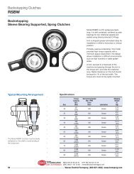
PNEUMATICCLUTCH-BRAKESEN ISO 9001:2000Certificate: 01 100 5695FRENO-EMBRAGUESNEUMÁTICOSDIST. AUTORIZADO®MEX (55) 53 63 23 31QRO (442) 1 95 72 60MTY (81) 83 54 10 18ventas@industrialmagza.com
I N D E XINTRODUCTION 2TECHNICAL INFORMATIONDEFINITIONSPERFORMANCE OF FRICTION MATERIALSBRAKING PROCESSTORQUE CALCULATION FOR AN ECCENTRIC PRESSPNEUMATIC SCHEMECLUTCH-BRAKE SERIES 5.815CLUTCH-BRAKE SERIES 5.723CLUTCH-BRAKE SERIES 5.031CLUTCH-BRAKE SERIES 5.5 and 5.639ACCESSORIES45PNEUMATIC CLUTCHES48PNEUMATIC SAFETY BRAKES 49WET CLUTCH-BRAKE SERIES 5.WSPECIAL CLUTCH-BRAKE UNITSPag.371012135155I N D I C EINTRODUCCIÓN 2Pag.INFORMACIÓN TÉCNICADEFINICIONES3COMPORTAMIENTO DE LOS ELEMENTOS DE FRICCIÓN7PROCESO DE FRENADO10CÁLCULO DEL PAR EN UNA PRENSA EXCÉNTRICA12ESQUEMA NEUMÁTICO13FRENO-EMBRAGUES SERIE 5.815FRENO-EMBRAGUES SERIE 5.723FRENO-EMBRAGUES SERIE 5.031FRENO-EMBRAGUES SERIES 5.5 y 5.639ACCESORIOS45EMBRAGUES NEUMÁTICOS48FRENOS NEUMÁTICOS DE SEGURIDAD 49FRENO-EMBRAGUES OLEONEUMÁTICOS SERIE 5.WFRENO-EMBRAGUES ESPECIALES5155DIST. AUTORIZADO®MEX (55) 53 63 23 31QRO (442) 1 95 72 60MTY (81) 83 54 10 18ventas@industrialmagza.com
C L U T C H E S - B R A K E SINTRODUCTIONINTRODUCCIÓN2This catalogue shows the full range of thepneumatic standard Goizper clutch-brakecombinations and accessories.Applications include Metalforming Presses,Shears, Die Cutters, Forming Machines, andCan Body Makers.We have added technical information to assistin the selection of our products.This catalogue is a reference only. Please donot hesitate to contact us for specialapplications related to these products.En el presente catálogo, dedicadoexclusivamente a nuestra línea de frenos,embragues, freno-embragues neumáticos,oleoneumáticos y sus accesorios, les ofrecemosnuestros modelos más actualizados de acuerdoa nuestros últimos desarrollos.Dichos productos son empleados en maquinariapara corte y deformación metálica, tal comoprensas, cizallas, plegadoras, etc.Se explican además los aspectos técnicos básicosrelacionados con los mismos: pares, tiemposde respuesta, comportamiento de los elementosde fricción, etc.Este catálogo no es más que la referencia dealgunos de los productos que fabricamos. Siprecisaran de información adicionalrelacionada con dichos productos, no dudenen contactarnos.DIST. AUTORIZADO®MEX (55) 53 63 23 31QRO (442) 1 95 72 60MTY (81) 83 54 10 18ventas@industrialmagza.com
F R E N O - E M B R A G U E STECHNICAL INFORMATIONThis chapter explains the basic concepts andformulas for the calculation and selection ofclutch-brakes for each application.All the formulas used in this catalogue are inaccordance with VDI 2241 and/or DIN 1304 norm.In case of any doubt or if any further informationis required, please do not hesitate to contact ourTechnical Department.INFORMACIÓN TÉCNICAEn este apartado se definen y explican losconceptos y fórmulas básicos necesarios para elcálculo y selección de los freno-embraguesadecuados para cada aplicación.Las designaciones, símbolos en las fórmulas y lasunidades utilizadas en este catálogo siguen lasnormas VDI 2241 y / o la DIN1304, normas dereferencia para este tipo de productos.En caso de cualquier duda, aclaración o interésen algún aspecto concreto, les rogamos se ponganen contacto con nuestro departamento técnico.DEFINITIONSDEFINICIONESTORQUESIt is important to define and difference the torquesconsidered in the clutching or braking process.The torque values shown in graph 1 are definedbelow.PARESPrimeramente es importante definir y distinguirlos distintos momentos o pares que se consideranen un proceso de embragado o frenado.El siguiente gráfico representa a cualquiera dedichos procesos:3Graph 1Slip or dynamic torque M s : this is the torquetransmitted once the torque increase time (t 12 )is finished. It changes within the cycle process anddepends, apart from other factors, on the slipspeed and the temperature of the friction surfaces.Transmissible torque or static torque M t :maximum admissible torque without slip,depending on the working and design conditions.Par de deslizamiento o par dinámico M s : parque actúa una vez finalizado el tiempo de subidade par (t 12 ). Varía durante el proceso de maniobray depende, entre otros factores, de la velocidadde deslizamiento y la temperatura de lassuperficies de fricción.Par transmisible o par estático M t : par máximoque admite el sistema actuado en función de lascondiciones de servicio y las condicionesmarginales del diseño, sin que se produzcaresbalamiento.DIST. AUTORIZADO®MEX (55) 53 63 23 31QRO (442) 1 95 72 60MTY (81) 83 54 10 18ventas@industrialmagza.com
C L U T C H - B R A K E S4Residual torque M r : torque transmitted whenthe system is not actuated. It depends onmounting position, (horizontal, vertical, orinclined), speed related to disc surface, oil flow,& viscosity.When vertical or inclined mounting, the residualtorque increases very much, so the generatedheat is increased as well.Loading torque M L : necessary torque to activatethe elements in the machine, taking into accountits performance, the action speed, etc.Characteristical torque M k : It is the torqueindicated in the catalogue.Acceleration torque M a (deceleration torquewhen the value is negative): torque indicatedin the catalogue. Usually equal to dynamic torque.This torque is calculated by using the followingformulation:MaBeing:= J (n 10 - n 20 ) (Nm)9,56 · tJ = moment of inertia (kgm 2 ).n 10 = driver shaft speed (r.p.m.).n 20 = driven shaft speed (r.p.m.).t = time (s).M a = acceleration torque (Nm).Par residual M r , par en vacío: par que transmiteel sistema cuando no está actuado. Depende desu posición (horizontal, vertical o inclinado), lavelocidad relativa de las superficies de las láminaso discos, de la viscosidad del aceite y caudal delmismo en caso de que el sistema trabaje en aceite.En caso de montaje vertical o inclinado el parresidual se incrementa de forma importanteaumentando el calor generado.Par de carga M L : par necesario para accionarlos elementos de la máquina teniendo en cuentasu rendimiento, la velocidad de accionamiento,etc.Par característico M k : par indicado en elcatálogo.Par de aceleración M a (par de deceleracióncuando el valor numérico es negativo): parnecesario para la aceleración de las masas en untiempo concreto.Dicho par se calcula por la fórmula:MaSiendo:= J (n 10 - n 20 ) (Nm)9,56 · tJ = momento de inercia (kgm 2 ).n 10 = velocidad del eje conductor (r.p.m.).n 20 = velocidad del eje conducido (r.p.m.).t = tiempo (s).M a = par de aceleración (Nm).FRICTION COEFFICIENTSTo calculate different torques, the followingcoefficients are considered.m: Sliding or dynamic friction coefficient.m 0 : Static friction coefficient.The ratio between both coefficients for thedifferent materials will be indicated in nextchapters.COEFICIENTES DE FRICCIÓNPara el cálculo de los distintos pares, seconsiderarán en este catálogo los siguientescoeficientes.m: Coeficiente de fricción dinámico o dedeslizamiento.m 0 : Coeficiente de fricción estático o deadherencia.La relación entre ambos coeficientes para losdistintos materiales se indicará en apartadosposteriores.DIST. AUTORIZADO®MEX (55) 53 63 23 31QRO (442) 1 95 72 60MTY (81) 83 54 10 18ventas@industrialmagza.com
F R E N O - E M B R A G U E STIME TERMS IN THE TORQUE TRANSMISSIONLike in the torques, it is important to definedifferent times existing in the torque transmissionthat appear in graph 1, which are:Reaction delay t 11 : time from the activation ofthe control until the beginning of the torqueincrease.Rising time t 12 : time from the beginning of thetorque increase until reaching the stationarycondition.Link time t 1 : sum up of the reaction delay timeand the rising time.t 1 = t 11 + t 12Slip time t 3 : time of relative movement betweenfriction surfaces of an actuated mechanism.Total time t t : Time from the signal until thetorque transmission is accomplished.t t = t 11 + t 3TÉRMINOS DE TIEMPO PARA ESTABLECERLA TRANSMISIÓN DEL PARDe la misma forma que en el caso de los pares,es importante definir los diferentes tiemposexistentes en el proceso de transmisión del par,y que aparecen reflejados en el gráfico 1.Estos son:Retardo de reacción al establecer latransmisión t 11 : tiempo desde la activacióndel mando hasta el comienzo de la subida delpar.Tiempo de subida t 12 : tiempo desde elcomienzo de la subida del par hasta alcanzarel estado cuasi estacionario.Tiempo de enlace t 1 : tiempo resultante de lasuma del retardo de reacción y el tiempo desubida.t 1 = t 11 + t 12Tiempo de deslizamiento t 3 : tiempo duranteel cual tiene lugar un movimiento relativo entrelas superficies de fricción de un mecanismoactuado.Tiempo total t t : tiempo desde que se da la señalhasta que se completa la transmisión del par.t t = t 11 + t 35TIME TERMS FOR INTERRUPTING THETORQUE TRANSMISSION (Graph 1)We define the torque transmission interruptiontimes in a similar way than we have done in theprevious paragraph.TÉRMINOS DE TIEMPO PARA INTERRUMPIRLA TRANSMISIÓN DEL PAR (Gráfico 1)Similarmente a lo indicado en el apartado anterior,se definen los distintos tiempos existentes en elproceso de interrupción de la trasmisión de par.Reaction time when interrupting thetransmission t 21 : Time from the deactivation ofthe control until the beginning of the torquedecrease.Decrease torque t 22 : Time from the torquedecrease until reaching 10% of the characteristicaltorque.Disconnection time t 2 : Sum up of the reactiondelay and the decrease time.t 2 = t 21 + t 22Retardo de reacción al interrumpir latransmisión t 21 : tiempo desde la desactivacióndel mando hasta el comienzo de la caída del par.Tiempo de caída t 22 : tiempo desde el comienzode la caída del par hasta alcanzar el 10 % del parcaracterístico.Tiempo de desconexión t 2 : suma del retardode reacción y el tiempo de caída.Por tanto: t 2 = t 21 + t 22DIST. AUTORIZADO®MEX (55) 53 63 23 31QRO (442) 1 95 72 60MTY (81) 83 54 10 18ventas@industrialmagza.com
F R E N O - E M B R A G U E SThe work produced by each cycle, which istransformed into heat, must be removedwithout surpassing the thermal capacity of theclutch-brake.In the pneumatic clutch-brakes the heat isabsorbed by the elements of the clutch-brakeand transmitted to the air by the surfaces thatare in contact with the atmosphere.In the hydraulic clutch-brakes, the heat isdissipated by means of lubrication oil.Lubrication can be done by splash, but whenan intense work is required a forced coolingwill be necessary, and lubrication will be donethrough the clutch-brake.El trabajo producido en cada maniobra, quese transforma en calor, debe ser evacuado sinsobrepasar la capacidad calorífica del frenoembrague.En los freno-embragues neumáticos el calor esabsorbido por los elementos del frenoembraguey transmitido al aire por lassuperficies que están en contacto con laatmósfera.En los freno-embragues hidráulicos el calor esdisipado fundamentalmente por medio delaceite de refrigeración. La lubricación puederealizarse por barboteo, aunque en los casosde un trabajo intenso será necesaria unarefrigeración forzada, para lo cual larefrigeración se hará por el interior del frenoembrague.PERFORMANCE OF FRICTIONMATERIALSDepending on some factors, which we detailbelow, the friction coefficient can changeduring the clutch or brake engagement. Thesefactors also affect when the torque istransmitted without relative movement amongthe friction surfaces:- Transmitted power.- Temperature on the friction surfaces(cooling system).- Slip speed.- Combination of friction materials.- Dry or wet operation.- Design of the friction surfaces (grooves…)- Pressure in the friction surfaces- Ambient temperature.- .....The combination of materials used in our clutchbrakesis the following:COMPORTAMIENTO DE LOSELEMENTOS DE FRICCIÓNLa variación del coeficiente de fricción durantela maniobra de embragado (o frenado), asícomo cuando se transmite el par sinmovimiento relativo entre las superficies defricción, depende de numerosos factores, entrelos cuales podemos destacar:- Potencia transmitida.- Temperatura en las superficies de fricción(sistema de refrigeración).- Velocidad de deslizamiento.- Combinación de materiales de fricción.- Funcionamiento en seco o lubricado.- Diseño de las superficies de fricción (canales,espirales...)- Presión en la superficie de fricción.- Temperatura del entorno.- .....A continuación se indican las combinacionesde materiales utilizados habitualmente ennuestros freno-embragues:7Type of clutch-brake Running Combination of materialsTipo de freno-embrague Medio Combinación de materialesPneumatic Dry Steel, cast iron/organic materialNeumático Seco Acero, hierro fundido / guarnición orgánicaHydraulic-Wet Wet Tempered steel / sintered bronzeHidráulico-Oleoneumático En aceite Acero templado / sinterizado de bronceDIST. AUTORIZADO®MEX (55) 53 63 23 31QRO (442) 1 95 72 60MTY (81) 83 54 10 18ventas@industrialmagza.com
C L U T C H - B R A K E SPNEUMATIC CLUTCH-BRAKES:These clutch-brakes work in dry condition andtherefore the friction materials are casting orsteel against organic asbestos-free material.The friction surfaces are flat and the organiclinings are bonded to the discs, leaving someradial slots free that permit the removal ofcontaminants and heat. Organic friction blockscan also be used.For a proper performance, the friction surfacesshould be free from grease and oil.FRICTION COEFFICIENTHigh friction coefficients are obtained (0,35 to0,45) with this combination of friction materials.In this case, there are no large differencesbetween the dynamic and static frictioncoefficients.FRENO-EMBRAGUES NEUMÁTICOS:Dichos freno-embragues trabajan en seco, siendolos elementos de fricción acero o fundido frentea guarnición orgánica sin amianto.En este tipo de freno-embragues las superficiesde fricción son lisas pero las guarniciones orgánicasvan pegadas a los discos porta-guarnicionesdejando entre sí unas ranuras radiales que sirvenpara la evacuación del abrasivo y del calor.También se pueden utilizar tacos de guarniciónorgánica alojados en los discos porta-tacos.Es necesario mantener las superficies de fricciónlimpias de grasa y aceite para un correctofuncionamiento.COEFICIENTE DE FRICCIÓNCon esta combinación de materiales de fricciónse obtienen elevados coeficientes de fricción (0,35a 0,45) sin grandes diferencias entre el coeficientedinámico y el estático.8WEAR OF THE LININGSLinings suffer wear. Wear is low when thetemperature of the metallic elements of theclutch-brake that are in contact with the liningdo not exceed a temperature of 170ºC. Abovethis temperature, wear increases considerably.It is important to take into account theatmosphere temperature where the clutchbrakeworks, as well as its position in themachine. There must be enough space to permitthe flow of fresh air at the clutch-brake.THERMAL CHARACTERISTICSOrganic linings are rated for 350ºC. Highertemperatures in short periods can be admissiblebut will incur in high wear.The dissipation capacity with constant cyclingcan be between 0,7-1,4 J/mm 2 min dependingon the factors indicated in the above headingcalled “performance of friction materials”.The energy produced per cycle and per surfaceof the unit should not exceed 2J/mm 2 ,consideration that will also be taken intoaccount when working in continuous mode.DESGASTE DE LAS GUARNICIONESLas guarniciones están siempre sometidas adesgaste. Este desgaste es bajo, siempre que latemperatura de los elementos metálicos del frenoembragueque contactan con las guarniciones nosuperen aproximadamente 170 ºC. Por encima deesta temperatura el desgaste aumentaconsiderablemente.Es importante tener en cuenta la temperaturaambiente del lugar donde trabaja el frenoembraguey su ubicación en la máquina, que debeestar provista de suficiente espacio y medios quepermitan la entrada libre de aire fresco a la zona.CARACTERÍSTICAS TÉRMICASLas guarniciones orgánicas pueden admitirpuntualmente temperaturas de hasta 350ºC.Temperaturas más elevadas en periodos muycortos de tiempo pueden ser admisibles a costade un desgaste muy elevado.El poder de disipación con cadencia constante demaniobras puede estar entre 0,7-1,4 J/mm 2 mindependiendo de los factores señalados en elapartado anterior “comportamiento de loselementos de fricción”.Además la energía producida por operación y porunidad de superficie no deberá pasar de 2 J/mm 2 ,consideración que también se tendrá en cuentacuando el funcionamiento es en continuo.DIST. AUTORIZADO®MEX (55) 53 63 23 31QRO (442) 1 95 72 60MTY (81) 83 54 10 18ventas@industrialmagza.com
F R E N O - E M B R A G U E SHYDRAULIC CLUTCH-BRAKES AND WET:Designed for wet operation, using temperedsteel against sintered bronze.The friction surfaces have been designed withgrooves, taking into account (among otherfactors) the thermal load, the friction coefficientand the lubrication oil flow.FRENO-EMBRAGUES HIDRÁULICOS YOLEONEUMATICOS:Diseñados para trabajo en aceite, empleansuperficies de acero templado frente asinterizado de bronce.En este caso, las superficies de fricción han sidodiseñadas con ranuras teniendo en cuentaentre otros factores, la carga térmica, elcoeficiente de fricción, y el caudal de aceite delubricación.FRICTION COEFFICIENTWith this combination of friction materials, thefollowing relation between the static anddynamic friction coefficient is obtained:m o= 1,7mCOEFICIENTE DE FRICCIÓNCon esta combinación de materiales de fricciónse obtiene una relación entre coeficiente defricción estático y dinámico deaproximadamente:WEAR OF THE SINTERED DISCS:Wear in this kind of combination is very low.It is important to assure appropriate lubricationof the friction surfaces and also to change oilregularly.m o= 1,7mDESGASTE DE LAS LÁMINAS SINTERIZADASEl desgaste en este tipo de combinación es muyreducido. Para ello, es esencial asegurar unaadecuada lubricación de las superficies defricción y también es importante cambiar elaceite regularmente.9THERMAL CHARACTERISTICSThe sintered discs have a very good thermalconductivity that allow temperatures up to350 ºC approx (depending on slipping time).The lubrication means in the friction surfaceshave a big influence in the heat dissipationproduced in each operation. The most commonvalues are the following:Splash lubrication: 0,7-1 J/mm 2 minForced lubrication: 1-2 J/mm 2 minThe energy produced per operation and persurface unit cannot exceed 1-2 J/mm 2 min (VDI2241).CARACTERÍSTICAS TÉRMICASLas láminas sinterizadas tienen muy buenaconductividad térmica lo que les permitesoportar temperaturas de hasta 350ºCaproximadamente (en función del tiempo dedeslizamiento).En la disipación del calor producido en cadaoperación influye grandemente el medio delubricación de las superficies de fricción. Losvalores más usuales son los siguientes:Lubricación por barboteo: 0,7-1 J/mm 2 minLubricación interior: 1-2 J/mm 2 minAdemás la energía producida por operación ypor unidad de superficie no deberá pasar de1-2 J/mm 2 min (VDI 2241).DIST. AUTORIZADO®MEX (55) 53 63 23 31QRO (442) 1 95 72 60MTY (81) 83 54 10 18ventas@industrialmagza.com
C L U T C H - B R A K E SBRAKING PROCESSPROCESO DE FRENADO10To calculate the slip time during the brakeengagement t 3 , the following formula is used:t 3 =t 12 J · w+ k ·2 M k(s)t 12 = time of torque increase.k = correction coefficient.J = Inertia referred to clutch-brake shaft(kgm 2 ).w = Angular speed of clutch-brake (rad/s).M k = Brake torque indicated in the catalogue(Nm).In the case of the pneumatic clutch-brake units,t 12 is very variable, depending on the series, sizes,torque rates and pneumatic circuit (2 - 80 ms.).In the case of the hydraulic ones, this value isinconsiderable.The K coefficient is function of the factorsindicated in chapter “performance of frictionmaterials”Its value is variable, considering for calculationk= 1,25, for both, pneumatic and hydraulicclucth-brake units.The total braking time will therefore be:t t = t 11 + t 3t 11 is also variable in both, pneumatic and hydraulicclutch-brake unitsPara el cálculo del tiempo de deslizamientodurante el proceso de frenado t 3 , se emplea lasiguiente fórmula:t 3 =t 12 J · w+ k ·2 M k(s)t 12 = tiempo de subida de par.k = coeficiente de corrección.J = inercias reducidas al eje del freno-embrague(kgm 2 ).w = velocidad angular del freno-embrague(rad/s).M k = par de freno de catálogo (Nm).En el caso de los freno-embragues neumáticos,el tiempo de subida t 12 es muy variable en funcióndel tipo, tamaño, combinación de muelles ycircuito neumático (2 - 80 ms.).En el caso de los hidraúlicos sin embargo, espracticamente despreciable.El coeficiente K es función de los factoresmostrados en el apartado “Comportamiento delos elementos de fricción”.Su valor es por tanto variable, estimándose parael cálculo k = 1,25 tanto para los freno-embraguesneumáticos como para los hidraúlicos.El tiempo total de frenado será:t t = t 11 + t 3t 11 también es variable tanto en los neumáticoscomo en los hidráulicos.Braking angle u f :The braking angle can be divided in two terms:1.- Reaction angle: u r = w · t 112.- Mechanical braking angle (u m ):u m = f (M, J, w, t 12, t 3 )u f = u r + u mTo simplify the calculation, the followingformulation can be used:wu f = w · t 11 + · t 3 (rad) ó2u f = 6 · n · t 11 + 3 · n · t 3 (º)n = Clutch-brake rotational speed (r.p.m.).Cálculo del ángulo de frenado u f :El ángulo de frenado u f se divide en dos términos:1.- Angulo de reacción: u r = w · t 112.- Angulo de frenado mecánico (u m ):u m = f (M, J, w, t 12, t 3 )u f = u r + u mPara simplificar el cálculo se puede utilizar lasiguiente fórmula:wu f = w · t 11 + · t 3 (rad) ó2u f = 6 · n · t 11 + 3 · n · t 3 (º)n = velocidad angular del freno-embrague(r.p.m.).DIST. AUTORIZADO®MEX (55) 53 63 23 31QRO (442) 1 95 72 60MTY (81) 83 54 10 18ventas@industrialmagza.com
F R E N O - E M B R A G U E SPlease find below graphics showingcomparasion measurements taken by anoscilloscope, of the brake engagement of ahydraulic clutch-brake and a pneumatic clutchbrakeaccordingly:A continuación se pueden ver los gráficos deejemplos de mediciones reales realizadas conosciloscopio, del proceso de frenado de unfreno-embrague hidráulico y de uno neumáticorespectivamente:SIGNAL -SPEED -TORQUE -PRESSURE -SpeedPressureTorqueSignal11Hydraulic clutch-brake unit<strong>Freno</strong>-embrague hidráulicoSpeedSIGNAL -SPEED -TORQUE -PRESSURE -TorquePressureSignalPneumatic clutch-brake unit<strong>Freno</strong>-embrague neumáticoDIST. AUTORIZADO®MEX (55) 53 63 23 31QRO (442) 1 95 72 60MTY (81) 83 54 10 18ventas@industrialmagza.com
C L U T C H - B R A K E STORQUE CALCULATION FOR ANECCENTRIC PRESSTo calculate the necessary torque in an eccentricpress, the following formulation is used:CÁLCULO DEL PAR EN UNA PRENSAEXCÉNTRICAPara el cálculo del par necesario en una prensaexcéntrica, se emplea la siguiente fórmula:M =sin ( a + b )cos b· P · rM =sen ( a + b )cos b· P · r12M : turning torque to be transmittedby the eccentrical shaft.a : maximum effort angle before the BDC(bottom dead center).P : force of the press.rbs: radius of the eccentric.: angle between the connectingrod and the movement line ofthe ram in the moment ofmaximum force.: distance from the BDC to thepoint where the maximum effort isproduced (measured at the ram).h : distance from the BDC to the pointwhere the maximum force is produced(measured at the eccentric).(fig. 1)M : momento de giro a trasmitir porel eje excéntrico.a : ángulo de esfuerzo máximo antesdel PMI (punto muerto inferior).P : esfuerzo de la prensa.r : radio de excéntrica.b : ángulo formado entre la bielay la línea del movimiento delcarro en el momento delesfuerzo máximo.s : distancia (medida en el carro)desde el PMI al punto dondese produce el esfuerzo máximo.h : distancia (medida en la excéntrica)desde el PMI al punto donde seproduce el esfuerzo máximo.To obtain angles “a” and “b”, and “h” height,the following formulations are used:r - hsin a = 1 - ( ) 2rPara la obtención de los ángulos “a” y “b”y la altura “h” se emplean las siguientesfórmulas:r - hsen a = 1 - ( ) 2rh =rLL 2 - ( L - s ) 22 · ( L - s + r )= sin bsin ah =L 2 - ( L - s ) 22 · ( L - s + r )r sen b =L sen aIn the case where the “r” and “L” values arenot known, an estimated calculation aboutthe transmissible torque can be done by usingthe following formulation:En el caso de que no se conozcan los valoresarriba indicados “r” y “L” se puede realizar uncálculo orientativo del par transmisibleutilizando la siguiente fórmula:M = F · r = sin ( a + b ) · P · r = K · P · rcos bM = F · r = sen ( a + b ) · P · r = K · P · rcos bTakingL = 5 (estimated), the K value is:rTomando L = 5 (orientativo), el valor de Kres:DIST. AUTORIZADO®MEX (55) 53 63 23 31QRO (442) 1 95 72 60MTY (81) 83 54 10 18ventas@industrialmagza.com
F R E N O - E M B R A G U E SFor a = 30° the coefficient K = 0,587For a = 15° the coefficient K = 0,3For a = 40° the coefficient K = 0,74For shears K = 1When the clutch is in a faster shaft:Para a = 30° el coeficiente K = 0,587Para a = 15° el coeficiente K = 0,3Para a = 40° el coeficiente K = 0,74Para cizallas K = 1Cuando el embrague está en un eje más rápido:M red = MiBeing i the transmission ratiobetween the clutch shaft andthe eccentric shaft.M red = MiSiendo i la relación detransmisión entre el eje delembrague y el eje excéntricoPNEUMATIC SCHEMEAn standard pneumatic scheme of the assemblyof a clutch-brake would be:1) Filter2) Pressure regulator3) Lubricator4) Air accumulator5) Electrovalve6) Rotary union7) Clutch-brakeESQUEMA NEUMÁTICOUn esquema neumático estándar para elmontaje de un freno-embrague sería elsiguiente:1) Filtro2) Regulador de presión3) Lubricador4) Acumulador de aire5) Electroválvula6) Rácor giratorio7) <strong>Freno</strong>-embrague13The quantity of air to be supplied by thecompressor should be calculated with thefollowing formulation:Q = 1,5 · V · p · F ( l/min )Q = necessary air quantityV = volume of the clutch cylinder plus thevolume of the pipe between the clutchand the valve indicated in the catalogue.p = maximum service pressure (bar).F = cycles per minute.1,5 = coefficient (compensation lost by leak).The volume of the recommended vessel comesfrom the following formulation:V DC = 4 · p · VV DC : accumulator volume (litres)La cantidad de aire a ser suministrada por elcompresor se calcula con la siguiente fórmula:Q = 1,5 · V · p · F ( l/min )Q = cantidad de aire necesariaV = volumen del cilindro del freno-embragueen el caso de desgaste máximo (apareceen el catálogo), más el volumen de latubería que hay entre el freno-embraguey la válvula.p = presión máxima de servicio (bar).F = frecuencia de maniobras por minuto.1,5 = coeficiente (compensación pérdida porfuga).El volumen del deposito recomendado (V DC )viene dado por la siguiente fórmula:V DC = 4 · p · VV DC : volumen del acumulador (litros)DIST. AUTORIZADO®MEX (55) 53 63 23 31QRO (442) 1 95 72 60MTY (81) 83 54 10 18ventas@industrialmagza.com
P N E U M A T I C C L U T C H - B R A K E S14DIST. AUTORIZADO®MEX (55) 53 63 23 31QRO (442) 1 95 72 60MTY (81) 83 54 10 18ventas@industrialmagza.com
F R E N O - E M B R A G U E S N E U M Á T I C O SCLUTCH-BRAKES SERIES 5.8 FRENO-EMBRAGUES SERIE 5.8This series corresponds to the latest of thepneumatic clutch-brakes developed by GOIZPER.One of its main characteristics is that it obtainsthe maximum possible torque within thedimensions of the unit, due to the fact thatthe piston reaches the maximum diameter.These clutch-brakes may be mounted withlocking rings or keyways.Esta serie corresponde al último de los frenoembraguesneumáticos desarrollados porGOIZPER.Entre sus características principales, destacaque se consigue el máximo par posible dentrode las medidas de la unidad, gracias a que elpistón alcanza el diámetro máximo.Estos freno-embragues están preparados paraser montados con anillos de fijación o conchavetas.Series 5.8 Serie 5.815DIST. AUTORIZADO®MEX (55) 53 63 23 31QRO (442) 1 95 72 60MTY (81) 83 54 10 18ventas@industrialmagza.com
P N E U M A T I C C L U T C H - B R A K E SSeries 5.81.__.WD *Series 5.82.__.WD *16Series 5.84.__.WD **Space to indicate the size / Espacio para indicar el tamañoDIST. AUTORIZADO®MEX (55) 53 63 23 31QRO (442) 1 95 72 60MTY (81) 83 54 10 18ventas@industrialmagza.com
P N E U M A T I C C L U T C H - B R A K E SSeries 5.85.__.WD *Series 5.85.__.WA *18Series 5.86.__.WD **Space to indicate the size / Espacio para indicar el tamañoDIST. AUTORIZADO®MEX (55) 53 63 23 31QRO (442) 1 95 72 60MTY (81) 83 54 10 18ventas@industrialmagza.com
P N E U M A T I C C L U T C H - B R A K E SASSEMBLY EXAMPLES / EJEMPLOS DE MONTAJE20Series 5.81.__. WDMounting between frame and flywheel by meansof identical pins on the clutch side as well as onthe brake side.Montaje entre bastidor y volante con bulonesiguales en el lado embrague y lado freno.Series 5.84.__. WDMounting at shaft end by means of pins ondifferent diameters on both clutch and brakeside. Fixed in the shaft by locking ring.Montaje en el extremo del eje con bulones en ellado embrague y en el lado freno situados endiametros distintos. Montado en el eje con anillofijación.Series 5.86.__. WEMounting at shaft end by means of pads in clutchside and pins in brake side. Fixed on the shaft bylocking ring.Montaje en el extremo del eje con tacos en ellado embrague y bulones en el lado freno.Montado en el eje con anillo de fijación.Series 5.83.__. CDMounting at shaft end by means of 12 bushingson the brake side and 2 pins on the clutch side.Fixed on the shaft by locking ring.Special air feeding via air inlet block.Montaje en el extremo del eje con 12 casquillosen el lado freno y 2 bulones en el lado embrague.Montado en el eje con anillo de fijacion.Alimentacion de aire especial.DIST. AUTORIZADO®MEX (55) 53 63 23 31QRO (442) 1 95 72 60MTY (81) 83 54 10 18ventas@industrialmagza.com
F R E N O - E M B R A G U E S N E U M Á T I C O STorque Ratings 5.8 / Rango de Pares 5.8SIZE2350101836557576777880QUANTITYOFSPRINGSBRAKETORQUE(N.m)CLUTCH TORQUE (N.m)5,5 bar 6 bar18 410 410 48515 345 480 56012 275 555 6309 205 625 7056 135 700 77518 + 18 800 800 95015 + 15 665 940 109012 + 12 535 1080 12309 + 9 400 1220 13706 + 6 270 1360 151018 + 18 1750 1700 205015 + 15 1450 2000 235012 + 12 1150 2350 26509 + 9 880 2650 29506 + 6 580 2950 329018 + 18 3400 3450 405015 + 15 2850 4000 465012 + 12 2250 4600 52509 + 9 1700 5200 58506 + 6 1150 5800 645018 + 18 6450 6400 760015 + 15 5390 7550 870012 + 12 4300 8650 98409 + 9 3200 9750 109006 + 6 2150 10800 1200021 + 21 9950 10450 1240018 + 18 8500 11900 1380015 + 15 7100 13400 1530012 + 12 5700 14900 168009 + 9 4250 16400 1830021 + 21 13000 13600 1610018 + 18 11200 15500 1800015 + 15 9300 17500 2000012 + 12 7400 19400 219009 + 9 5600 21400 2380021 + 21 19000 20000 2370018 + 18 16300 22900 2650015 + 15 13600 25700 2930012 + 12 10900 28500 322009 + 9 8150 31400 3500021 + 21 26700 28000 3310018 + 18 22850 32000 3710015 + 15 19000 36000 4110012 + 12 15200 40000 451009 + 9 11400 44000 4910021 + 21 35600 37500 4430018 + 18 30500 42800 4960015 + 15 25400 48100 5490012 + 12 20300 53400 602009 + 9 15200 58700 6550024 + 24 44000 50800 5970021 + 21 38500 56600 6550018 + 18 33000 62500 7130015 + 15 27500 68300 7710021DIST. AUTORIZADO®MEX (55) 53 63 23 31QRO (442) 1 95 72 60MTY (81) 83 54 10 18ventas@industrialmagza.com
F R E N O - E M B R A G U E S N E U M Á T I C O SCLUTCH-BRAKES SERIES 5.7 FRENO-EMBRAGUES SERIE 5.7This is the latest series of tradicional clutchbrakesdesigned by Goizper with maximumpiston size for each clutch-brake.Sizes 10, 18 and 36 are interchangeable withthe corresponding sizes in series 5.0.Sizes 55, 75, 76, 77 and 78 have the samediameters as their corresponding size fromseries 5.0 but are wider. They have very hightorques and can be mounted with locking ringsfrom both clutch and brake sides. Spacers areprovided to allow lining wear compensation.Esta serie consigue dentro del diseño tradicionalde freno-embrague de GOIZPER, el máximopar para cada uno de los diferentes tamaños.Los tamaños 10, 18 y 36 son intercambiablescon los mismos tamaños de la serie 5.0.Los tamaños 55, 75, 76, 77 y 78 tienen losmismos diámetros que los correspondientes dela serie 5.0 pero son más anchos, ademásofrecen unos pares muy elevados. Pueden irmontados con anillos de fijación tanto por ellado del embrague como por el del freno, ytienen la posibilidad de compensar el desgastede las guarniciones.Series 5.7Sizes · Tamaños: 05 / 11 / 16 / 23 / 50 / 10 / 13 / 18 / 3623Series 5.7Sizes · Tamaños: 19N / 25N / 37N / 55 / 75 / 76 / 77 / 78 / 80 / 81 / 82DIST. AUTORIZADO®MEX (55) 53 63 23 31QRO (442) 1 95 72 60MTY (81) 83 54 10 18ventas@industrialmagza.com
P N E U M A T I C C L U T C H - B R A K E SSeries 5.71.__.WD *Series 5.72.__.WD *24Series 5.74.__.WD **Space to indicate the size / Espacio para indicar el tamañoDIST. AUTORIZADO®MEX (55) 53 63 23 31QRO (442) 1 95 72 60MTY (81) 83 54 10 18ventas@industrialmagza.com
1117575320076,570,0130,0050,0030,0050,0350,075220-1731581935192212-10 (6)506565479,516-822-186513-4,5-M5(6)385,8242-10,5-M547166,66365710406012008685861,410,7680,530,7680,741,26610790500466501105353403025125190180133193525208060415171458746,55,5M147513,56958552720M12226,53195135182760196014504745470,50,2740,2020,2740,430,744956354083804590435330221810015314510913,5252516604531514,51239535,55,5M107010,55606802016M818226544919N3430249514505755570,650,2740,2020,2740,580,984956354083804590435330221811217216012913,525251660451912161339525,55,5M107010,55606802016M820527544923265185270098,590,0220,0320,0080,0320,0720,1225032520518825352262141410587070479,52020828280109618274,54,5M5385,82803611111M647176,665069549022501716170,050,0430,0270,0430,1450,273315410255236305227522214126697906510,5252012452808,511624395,54,5M6466,53604461611M611318,51110131465103017502726270,1730,1140,0620,1140,2760,462390490325305356534732214158212513081,513,525201445282,510141027495,54,5M8569,54355271611M81462327,525101465103017502625260,1730,1140,0620,1140,2760,462390490325305356534732214158212513081,513,52520134528112,514102746,55,54,5M8569,54355271611M81462127,525056528350065,560,0060,0030,0020,0030,020,045180-1351201424151212-9 (6)42606035916-818-26546-4,5-M4(6)306203-10,5-M535126,62,925N4785341013007473741,060,560,3820,560,781,3655071045042045954823323022125192166142172525206560257181448545,55,5M127513,56227752120M1024030548637N6720478012001071061071,720,8470,6090,8470,981,7661079050046650110535340302514021019015616,5352523806022,510,522165866,56,55,5M147513,56958552720M122683395135559500800010001491431493,811,351,041,351,452,5695885584543641506203403025160245250192203525248060251325186380,56,55,5M1484177809502720M1629037,51481357513400100009001971851975,582,141,552,141,763,1277099064059390165690545403018527027021420353528908039,512,5272065816,56,5M169617870107529,527M163294423021076191001580080027326427310,54,573,344,572,845,2880113572567510018077555545352053102902402645353811090381829218098,58,56,5M20110201000122038,529,5M163734723041077293002050075044343244319,277,516,517,514,458,2697012358107551251808655554540230320320256264535431109048,512,5342395107,58,56,5M24120211090133538,529,5M162905545071078390002760070065561565530,652010,7205,210,211001450890830125200950107565452483453502852660454515013034,526,5382599120,510,58,5M24138241260159552,543,5M18320607807101620512532006,566,50,0140,0090,0050,0090,040,062303051821661935198214141046751215192020825250,55,5841826,54,54,5M5385,82623371111M667156,6680500003600063076572376845,5526,613,126,66,911,7118015259659051402201025107565452603953703192660454515013038,522,5423299,5124,510,58,5M24138241340167052,543,5M185006878071081700005000056095391696380,633,62033,59,316,413001645108010151502401145107565502954504503663060454615013057,516,54632120,5134,510,58,5M27138241460179052,543,5M2057076780105082980007150050013601280134613929,217,329,212,521,914651855121511401703001276109075553304904904174260605518015059,519,55235142,515810,510,5M3013824165020156052,5M246288515001450F R E N O - E M B R A G U E S N E U M Á T I C O SSeries 5.71.__.WD / 5.72.__.WD / 5.74.__.WDSizeClutch torqueBrake torquePressurebarMax speed min -15.71 WDWeight 5.72 WDKg5.74 WDJ. int. Kg m 25.71 WDJ. ext. 5.72 WD Kg m 25.74 WDNew volMax. wear Volum.ØAØ A 1Ø A 2ØBMinMaxØDEØFØ F 1Ø F 2 12 x 30°GØHØ H 1ØIØ J 1K K 1K 2LL 1MNN 1Ø O 2 a 180°PP 1ØRØ R 1Ø R 2 12 x 30°SS 1ØTØ T 1UU 1WØYZTa 1Ta 2Nmdm 3Ø CH75,525NmNm®DIST. AUTORIZADOMEX (55) 53 63 23 31QRO (442) 1 95 72 60MTY (81) 83 54 10 18ventas@industrialmagza.com
P N E U M A T I C C L U T C H - B R A K E SSeries 5.75.__.WD *Series 5.75.__.WA *26Series 5.76.__.WD **Space to indicate the size / Espacio para indicar el tamañoDIST. AUTORIZADO®MEX (55) 53 63 23 31QRO (442) 1 95 72 60MTY (81) 83 54 10 18ventas@industrialmagza.com
P N E U M A T I C C L U T C H - B R A K E SASSEMBLY EXAMPLES / EJEMPLOS DE MONTAJE28Series 5.71.__.WDMounting between frame and flywheel by meansof identical pins on the clutch side and on thebrake side.Fixed to the shaft by locking ring.Montaje entre bastidor y volante con bulonesiguales en el lado embrague y lado freno.Montado en el eje con anillo de fijación.Series 5.72.__.ADMounting by means of 12 bushings on the clutchside and two pins on the brake side. Lateral airfeeding.Montaje en el estremo del eje con 12 casquillosen el lado embrague y dos bulones en el ladofreno. Alimentación lateral de aire.Series 5.74.__. CD (*)Mounting at shaft end by means of pins ondifferent diameters on both clutch and brakeside. Fixed in the shaft by locking ring.Special air feeding, via air inlet block.Montaje en el extremo del eje con bulones dellado embrague y lado freno situados en diámetrosdistintos. Montado en el eje con anillo de fijación.Alimentación de aire especial.Series 5.75.__. WAMounting between frame and flywheel by meansof pads in both clutch and brake side.Fixed to the shaft by locking ring.Montaje entre bastidor y volante con tacos enambos lados. Montado en el eje con anillo defijación.(*) If you are interested in CD type, please consult to GOIZPER(*) En el caso de estar interesado en el tipo CD, consulte con GOIZPERDIST. AUTORIZADO®MEX (55) 53 63 23 31QRO (442) 1 95 72 60MTY (81) 83 54 10 18ventas@industrialmagza.com
F R E N O - E M B R A G U E S N E U M Á T I C O STorque Ratings 5.7 / Rango de Pares 5.7SIZE51116235010131819N25N3637N5575767778808182QUANTITYOFSPRINGSBRAKETORQUE(N.m)CLUTCH TORQUE (N.m)5,5 bar 6 bar8 28 65 7510 75 175 20016 125 205 23514 110 220 25012 90 240 2708 62 270 30012 185 265 3109 135 315 3606 92 365 40510 + 10 490 695 80510 + 5 385 805 91510+ 0 275 920 10305 + 5 245 950 106012 + 12 1030 1465 169512 + 6 860 1645 187512 + 0 690 1820 20506 + 6 515 1995 222512 + 12 1030 1465 169512 + 6 860 1645 187512 + 0 690 1820 20506 + 6 515 1995 222512 + 12 1960 2760 319012 + 8 1690 3040 34809 + 6 1265 3480 39106 + 6 980 3770 420016 2495 3430 398014 2180 3755 430012 1870 4080 46258 1245 4730 527516 3410 4785 554014 2985 5225 598012 2555 5665 64208 1700 6545 720018 4060 5710 662015 3380 6410 731012 2710 7110 80109 2030 7810 871016 4780 6720 778514 4180 7340 840012 3585 7965 90258 2380 9200 1027016 8000 9500 1110014 7000 10500 1220012 6000 11600 132008 4000 13600 1530016 10000 13400 1560014 8700 14700 1690012 7500 16000 182008 5000 18600 2070016 + 16 15800 19100 2230012 + 16 13500 21400 2470010 + 10 9900 25300 285008 + 8 7900 27300 3050018 20500 29300 3400015 17100 32900 3750012 13700 36500 411009 10250 40000 4470020 + 20 27600 39000 4520016 + 20 23600 43200 4940010 + 20 17500 49500 5560010 + 10 13800 53400 5950024 + 24 36000 50000 5800020 + 20 30000 56500 6450016 + 16 24000 63000 7100012 + 12 18000 69000 7750024 + 24 50000 70000 8100020 + 20 41000 79000 9000016 + 16 33000 87000 9900012 + 12 25000 96000 10700024 + 24 71500 98000 11350020 + 20 59500 110500 12600016 + 16 47500 122500 13850012 + 12 35500 135000 15100029DIST. AUTORIZADO®MEX (55) 53 63 23 31QRO (442) 1 95 72 60MTY (81) 83 54 10 18ventas@industrialmagza.com
P N E U M A T I C C L U T C H - B R A K E S30DIST. AUTORIZADO®MEX (55) 53 63 23 31QRO (442) 1 95 72 60MTY (81) 83 54 10 18ventas@industrialmagza.com
F R E N O - E M B R A G U E S N E U M Á T I C O SCLUTCH-BRAKES SERIES 5.0 FRENO-EMBRAGUES SERIE 5.0Series 5.0 is the latest version of our traditionaldesign of clutch-brakes assembled by pins thattighten both covers for avoiding theirdeformation and breakage due to stress.The brake side cover is manufactured inaluminium, obtaining a low inertia.Los freno-embragues de la serie 5.0 son laúltima versión de nuestro tradicional diseñode freno embragues ensamblados por tirantes,los cuales atan ambas tapas para evitardeformaciones y roturas por fatiga.Otra de sus características es que la tapa ladofreno es de aluminio con lo que se consigueuna baja inercia.Series 5.0 Serie 5.031DIST. AUTORIZADO®MEX (55) 53 63 23 31QRO (442) 1 95 72 60MTY (81) 83 54 10 18ventas@industrialmagza.com
P N E U M A T I C C L U T C H - B R A K E SSeries 5.01.__.WD *Series 5.02.__.WD *32Series 5.04.__.WD **Space to indicate the size / Espacio para indicar el tamañoDIST. AUTORIZADO®MEX (55) 53 63 23 31QRO (442) 1 95 72 60MTY (81) 83 54 10 18ventas@industrialmagza.com
F R E N O - E M B R A G U E S N E U M Á T I C O SSeries 5.01.__.WD / 5.02.__.WD / 5.04.__.WDSizeClutch torqueBrake torquePressureNmBarMax speed min -15.01 WDWeight 5.02 WD Kg5.04 WDInt.J 5.01 WDExt. 5.02 WD Kg m 25.04 WDNew volMax. wear Volum.Ø AØ A 1Ø A 2Ø BØ CH7Ø DEØ FØ F 1Ø F 2GØ HØ H 1Ø IØ J 1KK 1MinMaxK 2LL 1L 2MNN 1Ø O 2 x 180°PP 1Ø RØ R 1Ø R 212 x 30°SS 1TT 1UU 1WØ YZTa 1Ta 2dm 3NmNm6069043023001615160,080,0430,0270,0430,1360,25534544028326532523052221412721051106610,525201445282511012827395,54,5M6466,53904751611M86620111010110058517502423240,190,1140,0620,1140,230,38539049032530535653473221415821251308210,5252017452830112,514102746,55,54,5M8569,54355271611M8822127,525182100137014504341430,460,2740,2020,2740,4820,792495635408380458043533022181001451459513,525251960453531514,51239535,55,5M107010,55606802016M8115265449364500293012007977791,230,7680,530,7680,7971,3761079050046650108535340302512519018012313,5352525806045415171458746,55,5M147513,56958552720M10145319513555700042505,510001221171222,731,3541,0441,3541,151 ,969588558454260114620540302514520620013616,5352530806050415191661866,55,5M1484177809502720M1216036,5148135751020059009001751631754,552,1441,5552,1441,472,4477099064059960125680545403016022522015016,5353532908060817,5201658846,56,5M169617870107529,527M1217041230210761430087008002382292387,374,573,3424,572,253,86880113572567575145775555453518526526516818,545353611090708202220831038,56,5M20110201000122038,529,5M142104823041077192001150076032431232413,257,516,517,512,834,98970123581075590160865555454020327627618622,5453540110908014202520941158,56,5M24120211090133538,529,5M162205345071078308001770060053751553729,8816,7812,616,785,378,71140145094588511518010005655542255300(330)3002122845454813011090202033281141478,58,5M24138241285157043,538,5M1825067450710794510027800450850--6232--7,3111300-108010001402201145-75--2953763762903260--150--57,516,5-32--10,5----1460-51---76780-33DIST. AUTORIZADO®MEX (55) 53 63 23 31QRO (442) 1 95 72 60MTY (81) 83 54 10 18ventas@industrialmagza.com
P N E U M A T I C C L U T C H - B R A K E SSeries 5.05.__.WD *Series 5.05.__.WA *34Series 5.06.__.WD **Space to indicate the size / Espacio para indicar el tamañoDIST. AUTORIZADO®MEX (55) 53 63 23 31QRO (442) 1 95 72 60MTY (81) 83 54 10 18ventas@industrialmagza.com
F R E N O - E M B R A G U E S N E U M Á T I C O SSeries 5.05.__.WD / 5.05.__.WA / 5.06.__.WDSizeClutch torqueBrake torquePressureNmbarMax speed min -15.05 WDWeight 5.05 WA Kg5.06 WDInt.J 5.05 WDExt. 5.05 WA Kg m 25.06 WDNew volMax. wear Volum.Ø A 1Ø A 2Ø BØ CH7MinMaxØ D 1Ø DEE 1Ø F 1Ø F 2Ø F 312 x 30°GØ HØ H 1Ø IØ J 1K1K 2L 1L 2M 1M 2N 1N 2Ø O 2 x 180°P 2Ø R 1Ø R 212 x 30°SS 1T 1U 1WØ YZTa 1Ta 2dm 3NmNm60690430230014-150,080,027-0,0270,1360,2554402832653252-3052-1412-721051106610,520142825-2111-8294,5M6466,547511M86620111010110058517502222230,190,0620,0450,0620,230,38549032530535653453473914158,5821251308210,52017283027241214,510344,5M8569,552711M8822127,525182100137014503941410,460,2020,1310,2020,4820,7926354083804580430435310,5221810,51001451459513,5251945353331,514,51512385,5M107010,568016M8115265449364500293012007375771,230,530,3410,530,7971,377905004665010853053531230251512519018012313,52525604538,532172114595,5M147513,585520M10145319513555700042505,510001111121172,731,0440,8811,0441,151,98855845426011462062051630251514520620013616,52530605045,5411924,516715,5M14841795020M1216036,5148135751020059009001531591634,551,5551,2611,5551,472,4499064059960125680680516,540301716022522015016,535328060575020261666,56,5M169617107527M1217041230210761430087008002202302297,373,3422,243,3422,253,8611357256757514577077551745352118526526516818,5353690705950223120836,5M2011020122029,5M142104823041077192001150076030129231213,256,5133,876,5132,834,98123581075590160860865518,545402520327627618622,5354090806657253420956,5M2412021133529,5M162205345071078308001770060049448251529,8812,68,4612,65,378,714509458851151809951000524554225255300(330)3002122845481109083,5733342,5281278,5M2413824157038,5M1825067450710794510027800450850--6232--7,311-10801000140220-1145-----29537637629032--------32---------76780-35DIST. AUTORIZADO®MEX (55) 53 63 23 31QRO (442) 1 95 72 60MTY (81) 83 54 10 18ventas@industrialmagza.com
P N E U M A T I C C L U T C H - B R A K E SASSEMBLY EXAMPLES / EJEMPLOS DE MONTAJE36Series 5.01.__.WDMounting between frame and flywheel by meansof identical pins in both clutch and brake side.Montaje entre bastidor y volante con bulonesiguales en el lado embrague y lado freno.Series 5.02.__.ADMounting at shaft end by means of 12 bushingson the clutch side and two pins on the brake side.Lateral air feeding.Montaje entre bastidor y volante con 12 casquillosen el lado embrague y dos bulones en el ladofreno. Alimentación lateral de aireSeries 5.04.__.WDMounting at shaft end by means of pins ondifferent diameters on both clutch and brakeside.Montaje en extremo de eje con bulones del ladoembrague y lado freno situados en diámetrosdistintos.Series 5.05.__.WAMounting between frame and flywheel by meansof pads in both clutch and brake side.Fixed in the shaft by locking ring.Montaje entre bastidor y volante con tacos enambos lados. Montado en el eje con anillo defijación.DIST. AUTORIZADO®MEX (55) 53 63 23 31QRO (442) 1 95 72 60MTY (81) 83 54 10 18ventas@industrialmagza.com
F R E N O - E M B R A G U E S N E U M Á T I C O STorque Ratings 5.0 / Rango de Pares 5.0SIZEQUANTITYOFSPRINGSBRAKETORQUE(N.m)CLUTCH TORQUE (N.m)5,5 bar 6 bar6010183655757677787912 430 690 8009 320 800 9006 215 900 100018 585 1100 120015 485 1200 130012 390 1300 14009 290 1400 150016 1370 2100 240012 1025 2400 280010 855 2600 29008 685 2800 310018 2930 4500 520015 2445 5000 570012 1955 5500 62008 1465 6000 670018 4250 7000 800015 3550 7700 870012 2850 8400 95009 2125 9200 1020024 5900 10200 1170020 4900 11200 1270016 3900 12300 1380012 2950 13300 1480018 8700 14300 1650015 7200 15800 1800012 5800 17400 195009 4300 18900 2100018 11500 19200 2200015 9600 21200 2400012 7700 23200 260009 5750 25200 2800018 17700 30800 3530015 14800 33900 3830012 11800 36900 414009 8850 40000 4440018 27800 45100 5180015 23200 49900 5670012 18500 54700 615009 13900 59600 6630037DIST. AUTORIZADO®MEX (55) 53 63 23 31QRO (442) 1 95 72 60MTY (81) 83 54 10 18ventas@industrialmagza.com
P N E U M A T I C C L U T C H - B R A K E S38DIST. AUTORIZADO®MEX (55) 53 63 23 31QRO (442) 1 95 72 60MTY (81) 83 54 10 18ventas@industrialmagza.com
F R E N O - E M B R A G U E S N E U M Á T I C O SCLUTCH-BRAKESSERIES 5.5 and 5.6Series 5.5 corresponds to clutch-brakes withdouble disc in the clutch side, in order to geta lower inertia. Their external covers and hubsare made of electro-welded steel.Series 5.6 is similar to 5.5 but has double discin both sides, improving the torque-inertia rate.FRENO-EMBRAGUESSERIES 5.5 y 5.6La serie 5.5 corresponde a las ejecuciones defreno-embrague con doble disco en el lado delembrague, con objeto de conseguir una menorinercia. Sus tapas exteriores y moyús estánfabricados en acero electrosoldado.La serie 5.6 es similar a la 5.5, pero se diferenciaen que lleva doble disco tanto en el lado delembrague como en el del freno con lo que larelación par-inercia mejora.Series 5.5 Series 5.639DIST. AUTORIZADO®MEX (55) 53 63 23 31QRO (442) 1 95 72 60MTY (81) 83 54 10 18ventas@industrialmagza.com
P N E U M A T I C C L U T C H - B R A K E SSeries 5.51.__.WD *40Series 5.54.__.WD **Space to indicate the size / Espacio para indicar el tamañoDIST. AUTORIZADO®MEX (55) 53 63 23 31QRO (442) 1 95 72 60MTY (81) 83 54 10 18ventas@industrialmagza.com
F R E N O - E M B R A G U E S N E U M Á T I C O SSizeClutch torqueBrake torquePressureNmbarMax speed min -1WeightKgJInt.Ext.Kg m 2New volMax. wear Volum.Ø AØ A 1Ø BØ CH7MinMaxØ DØ FØ F 1Ø FFG 3Ø HØ H 1Ø IØ JKK 1K 2LL 1LLMNØ O 2 a 180°P 1Ø RØ R 1Ø R 2TT 1UU 1VWØ YZTa 1dm 3Nm18420013701400660,710,6370,71,24956353804580435302240134140(145)*1409513,535252560458041512906,55,55,5560680201627M81102654369000293011001121,831,7751 ,12,261079046650108535403050169160(190)*16012313,53525358060100615141206,55,56,5695855272032M121323195551400042509501583,231,5369588554260114620403050190180(206)*1801321735253580601007,515161336,55,56,5780950272032M1215536,5148Series 5.51.__.WD / 5.54.__.WD752040059008502115,94,7451,93,977099059960125680454055209190(225)*19015017453535908011012,517,5161358,56,56,58701 07529,52738,5M1216541230762860087005,575031310,410,12,45,2880113567575145775554565242225(265)*22516818,5453545110901301420201608,56,58,51000122038,529,543,5M161854823077384001150070042417,716,272,96,8970123575590160865554565260240(276)*24018622,5453545110901301420201748,56,58,51090133538,529,543,5M16210534507861600177005507223936,364,310,3114014508851151801000655575331300(330)*300212284545451301101602020282258,58,58,51285157043,538,548,5M1825067450799020027800400112080656131300-1000140220114575-853613763762903260-60150-18057,516,532-10,5--1460-51----767808113800035500350168015515010,917,5146518551140150260127690751004004284283404060606018015021057,519,535217,510,510,510,5165020156052,5652434085159041*The measurements between brackets are in the case of lateral air feeding*El valor entre paréntesis es para casos de entrada lateral de aireDIST. AUTORIZADO®MEX (55) 53 63 23 31QRO (442) 1 95 72 60MTY (81) 83 54 10 18ventas@industrialmagza.com
P N E U M A T I C C L U T C H - B R A K E SSeries 5.61.__.WD *42Series 5.64.__.WD **Space to indicate the size / Espacio para indicar el tamañoDIST. AUTORIZADO®MEX (55) 53 63 23 31QRO (442) 1 95 72 60MTY (81) 83 54 10 18ventas@industrialmagza.com
F R E N O - E M B R A G U E S N E U M Á T I C O SSizeClutch torqueBrake torquePressureNmbarMax speedWeightmin -1KgJInt.Ext.Kg m 2New volMax. wear Volum.Ø AØ A 1Ø BØ CH7MinMaxØ DØ FØ F 1Ø FFG 4Ø HØ H 1Ø IØ JKK 1K 2LL 1LLMNØ O 2 a 180°PP 1Ø RØ R 1Ø R 2TT 1UU 1VWØ YZTa 1dm 3Nm18420027401400660,710,630,71,24956353804580435302040134140(145)*1409513,535352560708033151228,5906,55,55,5560680202727M81102654369000586011001382,31,771,12,261079046650108535405050169160(190)*16012313,53535358090100381514391206,56,56,5695875273232M12132319555140008500950194431,5369588554260114620405050190180(206)*18013217353535809010038151636,51336,56,56,5780970273232M1215536,5148Series 5.61.__.WD / 5.64.__.WD7520400118008502577,44,741,93,977099059960125680455555209190(225)*19015017454535901001103817,516351358,58,56,5870107529,538,538,5M12165412307628600174005,575037712,610,12,45,2880113567575145775556565242225(265)*22516818,545454511011013048202042,51608,58,58,51000122038,543,543,5M161854823077384002300070051922,116,272,96,8970123575590160865556565260240(276)*24018622,5454545110110130482020471748,58,58,51090135538,543,543,5M16210534507861600354005508804936,364,310,3114014508851151801000657575331300(330)*3002122845454513013016058202856,52258,58,58,51285160043,548,548,5M1825067450799020055600400134099656131300-1000140220114575-853613763762903260-60150-180-16,532--10,5--1460-51----767808113800071000350190019014010,618,214651855114015026012769075100400428428340406060601801502103019,53550217,510,510,510,5165020156052,5652434085159043*The measurements between brackets refer to clutch-brakes with lateral air feeding*El valor entre paréntesis es para casos de entrada lateral de aireDIST. AUTORIZADO®MEX (55) 53 63 23 31QRO (442) 1 95 72 60MTY (81) 83 54 10 18ventas@industrialmagza.com
P N E U M A T I C C L U T C H - B R A K E SASSEMBLY EXAMPLES / EJEMPLOS DE MONTAJE44Series 5.51.__. WDMounting between frame and flywheel by meansof 4 pins at 90º on the clutch side and 2 pins onthe brake side all of them on the same diameter.Fixed in the shaft by locking ring.Montaje entre bastidor y volante con 4 bulonesa 90º en el lado embrague y 2 bulones en el ladofreno situados todos ellos en el mismo diámetro.Montado en el eje con anillo de fijación.Series 5.54.__. ADMounting at shaft and by means of 4 pins at 90ºon the clutch side and 2 pins on brake side ondifferent diameters.Lateral air feeding.Montaje en el extremo del eje con 4 bulones a90º en el lado embrague y 2 bulones en el ladofreno situados en diámetros distintos.Alimentación lateral de aire.Series 5.61.__. WDMounting between frame and flywheel by meansof 4 pins at 90º on the clutch side and 4 pins at90º on the brake side, all of them on the samediameter.Montaje entre bastidor y volante con 4 bulonesa 90º en el lado embrague y 4 bulones a 90º enel lado freno, situados todos ellos en el mismodiámetro.Series 5.64.__. WDMounting at shaft and by means of 4 pins at 90ºon the clutch side and 2 pins connected to doublediscs on brake side, on different diameters.Montaje en el extremo del eje con 4 bulones a90º en el lado embrague y 2 bulones conectadosa doble disco en el lado del freno, situados endiámetros distintos.DIST. AUTORIZADO®MEX (55) 53 63 23 31QRO (442) 1 95 72 60MTY (81) 83 54 10 18ventas@industrialmagza.com
F R E N O - E M B R A G U E S N E U M Á T I C O SACCESSORIESAIR INLET DISCWhen the clutch-brake is mounted at the shaftend, it can be fed by a lateral air inlet.In this way, the shaft is shorter and it eliminatesthe need to drill the shaft.ACCESORIOSDISCO DE ALIMENTACIÓN LATERALEn los casos en que el freno-embrague estésituado en el extremo del eje, puede seralimentado por medio de un disco dealimentación lateral suministrado por GOIZPERy que va atado al eje por medio de 4 tornillos.De esta forma, el eje es más corto y se evitamecanizar los agujeros de alimentación de aire.Series 5.7 SizeØ AØ CØ EGHLØ PØ SØ T - 4 x 90ºØ UWeight kg.J kgm 2 MINMAX50 10-13101 128M 22 x 1,531 311,5 2,516 1636 3610,5 10,5M 6 M 652 521 1,80,0018 0,004444 5052 6518156343204413,5M 8652,50,0096609019N175M343204413,5M 8653,750,014459525N19627 x 1,5343204813,5M 8704,80,021451003619337,53255616,5M 10804,80,0246811037N21437,53255616,5M 108060,0327011555250M 3539,53355618,5M 12809,130,0787013075275x 1,5473355618,5M 1211213,550,1369015576315473358025M 1611217,20,23210017277312M 50 x473358025M 1611215,40,209125180783461,5533358025M 16112220,31712520080395M603359825M 1613229,40,5961402208144865 x603359825M 1613258,30,88150240825021,56634110025M 16135571,6441702704560Series 5.0 Size10 18 36 55 75 76 77 78J kgm 2 0,0020 0,0040 0,0068 0,023 0,031 0,058 0,116 0,125 0,302Ø A 105 126 145 188 205 225 265 275 330Ø CMIN 44 44 55 68 70 70 75 100 115MAX 52 65 80 108 114 125 145 160 180Ø EM 22 x 1,5 M 27 x 1,5 M 35 x 1,5 M 50 x 1,5GHLØ PØ SØ T - 4 x 90ºØ UWeight kg.311,5163610,5M 6521,1312,5163610,5M 6521,8343204413,5M 8652,337,53255616,5M 10804,639,53355618,5M 12805,5413355618,5M 12806,6443355618,5M 128011473358025M 1611212533358025M 1611219The lateral air feeding can be also used in theseries 5.5 and 5.6El disco de alimentación lateral también puedeser usado en las series 5.5 y 5.6.DIST. AUTORIZADO®MEX (55) 53 63 23 31QRO (442) 1 95 72 60MTY (81) 83 54 10 18ventas@industrialmagza.com
P N E U M A T I C C L U T C H - B R A K E SAIR ROTARY INLET / RACORES GIRATORIOS7.017.0246SERIES 7.01 - 7.02Size00 02 12030406Ø AR 1 / 4 ”R 1 / 2 ”R 3 / 4 ”R 1”R 1 1 / 2 ”R 2”Ø B71318253848Ø CM14 x 1,5M22 x 1,5M27 x 1,5M35 x 1,5M50 x 1,5M65 x 1,5Ø D46627080100125E121215172225G131215152225L8295114127165199L 195111133149198240E.C.I274146557595E.C.II172428325065ForsizesSeries 5.05.5 y 5.6Series 5.705-1160-1023-50-10-1318-3618-19N25N-36-37N55-75-7655-7577-7876-77-7879-8180-81-82Series 5.823-50-101836-55-7576-77-7880DIST. AUTORIZADO®MEX (55) 53 63 23 31QRO (442) 1 95 72 60MTY (81) 83 54 10 18ventas@industrialmagza.com
F R E N O - E M B R A G U E S N E U M Á T I C O SQUICK EXHAUST ACCESSORY / ACCESORIO DE ESCAPE RÁPIDOSeries 7.06Size0212030406ØAM 22 x 1,5M 27 x 1,5M 35 x 1,5M 50 x 1,5M 65 x 1,5ØBM 22 x 1,5M 27 x 1,5M 35 x 1,5M 50 x 1,5M 65 x 1,5ØD123160185230250ØE1318253648ØF89121419ØG10.2510.2510.2512.2512.25H729198119134J1215152225K1418181821L79101414M2023314052N45,547,547,54541,5E.C.Weight kg321,7413,8555,5759,69515,747Inertia Kgm 20,00370,01540,02930,07380,214ForsizesSeries 5.0Series 5.7Series 5.860-1050-1023-50-1018-3618-25-361855-75-7655-7536-55-7577-78-7976-77-7876-77-7880ASSEMBLY EXAMPLES / EJEMPLOS DE MONTAJEDIST. AUTORIZADO®MEX (55) 53 63 23 31QRO (442) 1 95 72 60MTY (81) 83 54 10 18ventas@industrialmagza.com
P N E U M A T I C C L U T C H - B R A K E SSeries 5.35PNEUMATICALLY ACTUATED MULTI DISC CLUTCHESEMBRAGUES NEUMÁTICOS MULTIDISCO48Series 5.35Size 16 32 64 90 12 18 36 55 75 76 77 81Torque Nm 160 320 640 900 1.280 1.800 3.600 5.500 7.500 10.000 15.000 22.000Pressure Bar 5,5Speed max. min-1 3.500 3.500 2.800 2.100 2.000 1.900 1.900 1.900 1.500 1.400 1.000 1.000Weight kg 10 12 20 25 32 50 56 72 85 120 300 340Int 0,019 0,027 0,112 0,140 0,3 0,47 0,5 0,9 1,3 1,8 7 7,5J Kg cm 2Ext. 0,01 0,012 0,03 0,06 0,15 0,19 0,21 0,25 1,3 1,8 3 4New volum. 0,06 0,08 0,12 0,20 0,35 0,70 0,70 1,30 1,40 1,40 2,30 2,50dm 3Max. wear volum. 0,13 0,20 0,35 0,48 0,85 1,40 1,70 2,40 2,60 3 4 4,50Ø A min. 20 25 30 30 30 50 50 70 70 70 50 100Ø A max. 50 50 70 70 90 100 100 130 130 130 150 150Ø C min. 50 50 85 85 100 90 120 180 180 180 200 200Ø C max. 110 110 160 160 230 260 260 340 340 340 480 480Ø D 165 165 225 225 295 345 345 444 444 444 600 600Ø H 8 8 10 10 10 10 12 14 14 14 14 14L 80 87 100 110 115 130 140 145 160 167 200 225M 10 10 10 10 10 15 15 20 20 20 20 20P 22 22 25 25 30 35 35 40 40 40 60 60ØY 1 - - - - 110 120 120 146 152 152 186 186Ø Y 60 60 80 80 110 120 120 180 180 180 210 210Ø Z 2x180º M6 M6 M6 M6 M12 M12 M12 M12 M12 M12 M12 M16DIST. AUTORIZADO®MEX (55) 53 63 23 31QRO (442) 1 95 72 60MTY (81) 83 54 10 18ventas@industrialmagza.com
F R E N O - E M B R A G U E S N E U M Á T I C O SSeries 5.36PNEUMATIC SAFETY BRAKESFRENOS NEUMÁTICOS DE SEGURIDADSeries 5.36Size 05 10 25 30 74 75 76 77 78 794Dynamic 3 1 friction discbrake 2torque 43 2 friction discsMd 2(Nm) 43 3 friction discs2Max. Speed n min -1Spring return pressure(bar)Max. Stroke volume dm 3J1 friction discInt.2 friction discs3 friction discskg m1 friction discWeight 2 friction discs kgØ AØ B maxØ CØ DØ EØ FØ GH1H2H3JKL1 maxL2 maxL3 maxM1 maxM2 maxM3 maxNO (3x120º)R1R2R3S (Gap)TTTUVW1W2W3Ø XØ YØ Z3 friction discs1851409036528018553541526528000,0520,0040,0080,0096,39,210,1195556611816715613011,515,0014,543,584,595,17108,577,591,671054,5R 1/8”5869,1782,50,5M6M512,56,532465918575114365255185720510365111078055522400,1020,010,0210,02210,31516,5235757514020018815611,515,501553,595106,8312286,5101,831175R 1/4”6677,83930,5M8M612,57,5355065,522395132,57105353551415105567520201555101017000,1690,0310,0610,071927,530,53001001151852602402051818,2517,2574112,25118,42135,75106,5112,92130,255,75R 1/4”76,7583,671011M10M813,7510455875284144180131094564025251890126538402890192014500,340,0690,1340,16530,54349,536013013022030928624022,2521,7520,5104,5129,25145,00164122,25136,001555R 1/2”86,5101,75118,751,2M12M1017,5125265843401602071820131091040402780202060604220313012500,5070,1460,2850,3174260,56740515514025535432527021,7519,0020105,5142,25159,83182,5133,5149,331727R 3/4”97,25114,83137,51,2M12M1018,51257729538519023228302000141556554445283080806670404011200,6030,2160,430,553568594,545517017028539436532017,7517,0019125,5156,75175,83200138,5158,831838,5R 1”105,25124,33148,51,2M14M1221155676100430200270424028902120808058904240126258890636510000,660,4510,8191,041141461655052001703154404053504926,0024,75155,5164, 5194223,5168,5174,5201,52R1”99125,51551,2M16M12301582881154802452875550389028301060083305350161601278080808500,6941,0901,8492,4001141682015902252503605074704202218,7523,75186182,75203,33235167,25191,08222,759,25R 1”125,75148,331801,2M16M1419,5187097128562270360808055554040161601167078802323017780116157501,2681,3642,7064,14316123327767028531344059054249026,7522,0027,5207212,75236,17272,5188212,17248,53,5R 1”139,75163,17199,51,5M20M1631,5208010414063733043011110778055552222016670107003333024445161606702,232,6155,2076,5312263293867402853254606505925303233,0037,5207,5229257,67294214,5248,6728513,5R 1 1/4”159,5188,17224,51,5M20M1626,52090124160708330462,549DIST. AUTORIZADO®MEX (55) 53 63 23 31QRO (442) 1 95 72 60MTY (81) 83 54 10 18ventas@industrialmagza.com
P N E U M A T I C C L U T C H - B R A K E S50DIST. AUTORIZADO®MEX (55) 53 63 23 31QRO (442) 1 95 72 60MTY (81) 83 54 10 18ventas@industrialmagza.com
F R E N O - E M B R A G U E S N E U M Á T I C O SWET CLUTCH-BRAKESERIES 5.WThis series of clutch-brake is the version of thepneumatic actuated and hidraulicallyrefrigerated multiplate clutch-brake.It combines the engagement of the pneumaticclutch-brake, with the refrigeration capacityof the hydraulic clutch-brakes. As a result, weobtain a clutch-brake with the possibility of ahigh frequency of engagements.The disc refrigeration could be plunged in oil,(no external circuit) or with a forcedrefrigeration or external circuit, depending onthe required disipation energy of the aplication.FRENO-EMBRAGUEOLEONEUMÁTICO SERIE 5.WÉste es el freno-embrague multidisco actuadoneumáticamente y refrigerado por aceite.Esta serie de freno-embrague combina elaccionamiento del embrague neumático conla capacidad de refrigeración de los embragueshidráulicos. Como resultado tenemos un frenoembraguecon la posibilidad de obtener unaalta frecuencia de maniobras.La refrigeración se produce dependiendo dela energía de disipación requerida por laaplicación, esta refrigeración puede ser forzadapor medio de un circuito exterior, para lo cualel freno-embrague está preparado.51DIST. AUTORIZADO®MEX (55) 53 63 23 31QRO (442) 1 95 72 60MTY (81) 83 54 10 18ventas@industrialmagza.com
P N E U M A T I C C L U T C H - B R A K E SSeries 5.W152Series 5.W5DIST. AUTORIZADO®MEX (55) 53 63 23 31QRO (442) 1 95 72 60MTY (81) 83 54 10 18ventas@industrialmagza.com
F R E N O - E M B R A G U E S N E U M Á T I C O SSeries 5.W1 / 5.W5DYNAMICBRAKETORQUESTATICCLUTCHTORQUEMax speedWeight (8+8 discs)J.intVolum (8+8 discs)L0PZ2SeriesSize 75 77 78 81 82Brake side discs= 5Brake side discs= 6Brake side discs= 7Brake side discs= 8Brake side discs= 9Brake side discs= 10Clutch side discs= 5Clutch side discs= 6Clutch side discs= 7Clutch side discs= 8Clutch side discs= 9Clutch side discs= 10Total discs= 10Total discs= 20Ø AØ BØ C (H7)Ø C1Ø C2 (g7)Ø C3 (12X30°)Ø DEE1 maxF2Total discs= 10Total discs= 12Total discs= 14Total discs= 16Total discs= 18Total discs= 20M1NØ OBrake side discs= 5Brake side discs= 6Brake side discs= 7Brake side discs= 8Brake side discs= 9Brake side discs= 10RSS1TZ1Brake side discs= 5Brake side discs= 6Brake side discs= 7Brake side discs= 8Brake side discs= 9Brake side discs= 10minmaxNmNmmin-1KgKg m2dm35.W1 5.W5 5.W1 5.W5 5.W1 5.W5 5.W1 5.W5 5.W1 5.W5910.440.5714601760205023502640293032703910454051505770637013000.2570952602773103301129681352001311431551671791914070846525864707631156121491971031091151211010.510.6427003300380044004900550063007600880010000113001250010001741.131.470.478011532035040042513.538012155250136149162175188201501081048.55561.56874.581388561614.596.5103109.5116122.51292021.411.7554006500760087009800109001000012000139001580017600195008502842.923.750.7710515039041547050017.54401220030017619220822424025660116136472808896104468562026.51291371451531611693193.484.311080013000152001730019500217002130025500296003360037700416007005308.5410.8761310.3812.711.3812018049053059063022560122353802042222402582762946513216788796105114123592562524141150159168177186206002470028800329003700041200459005470063400720008060089200500107631.3140.38118136.2745.332.771602506306707508002671015305475270294318342366390751742010611813014215416675556303218619821022223424653DIST. AUTORIZADO®MEX (55) 53 63 23 31QRO (442) 1 95 72 60MTY (81) 83 54 10 18ventas@industrialmagza.com
P N E U M A T I C C L U T C H - B R A K E SAIR ROTARY INLET / RACORES GIRATORIOSSeries7.07.12.9087.07.03.9127.07.04.90954Ø BCØ DEØ FØ GØ HØ J (g6)KLMXFor Sizes141/2"Gas9015264464753/4"Gas140M6 (4x90°)1075-77233/4"Gas11017345778931"Gas153M8 (4x90°)1078-81321"Gas1362243721001181 1/2"Gas184M10 (4x90°)1682ASSEMBLY EXAMPLE / EJEMPLO DE MONTAJEDIST. AUTORIZADO®MEX (55) 53 63 23 31QRO (442) 1 95 72 60MTY (81) 83 54 10 18ventas@industrialmagza.com
F R E N O - E M B R A G U E S N E U M Á T I C O SSPECIAL CLUTCH-BRAKE UNITSFRENO-EMBRAGUES ESPECIALESOnly brake version. It is in fact a safety pneumaticbrake.Versión solo freno. Es en realidad un frenoneumático de seguridad.Clutch-brake unit with quick exhaust. To get veryquick braking response time.<strong>Freno</strong>-embrague con escape rápido. Se consiguentiempos de respuesta en frenadaconsiderablemente bajos.55Clutch-brake with planetary gear.<strong>Freno</strong>-embrague con reductor planetario.Pneumatic safety brake.<strong>Freno</strong> neumático de seguridad.DIST. AUTORIZADO®MEX (55) 53 63 23 31QRO (442) 1 95 72 60MTY (81) 83 54 10 18ventas@industrialmagza.com
F R E N O - E M B R A G U E S N E U M Á T I C O SGOIZPER Koop.Elk.Data form for mechanical presses CL-BR unit selectionDatos para la selección de freno-embragues para prensasCUSTOMER / ClienteResponsible / ResponsableDpt./ Dpto:Phone / Teléfono Fax: Date / Fecha:Characteristics of the press: Type / Tipo Model / ModeloCaracterísticas de la prensa Single Stroke / Golpe a golpe Continuous run./ en continuoCL-BR mounting:Montaje del F-E:End of the shaft / Extremo del ejeBetween frame and flywheel / Entre bastidor y volanteType of CL-BR unit required:Tipo de F-E solicitadoPneumatically actuated / NeumáticoHydraulically actuated / HidráulicoTECHNICAL DATA OF THE PRESS / Datos técnicos de la prensa1. Max force of the press. F = kNFuerza máxima de la prensa2. Crankshaft radius r = mmRadio de la excéntrica563. Side rod length L = mmLongitud de la biela4. Working angle before B.D.C. a = ºÁngulo de trabajo antes del P.M.I.Or effective working length h = mmÓ altura efectiva de trabajoOr working length s = mmÓ altura de trabajo5. Crankshaft max speed n c = min -1Revoluciones max del eje de la excéntrica6. CL-BR max speed n c = min -1Revoluciones max del F-E trabajando golpe a golpe7. Moment of inertia of all the masses to be braked, reduced to the cl-br shaft (CL-BR inertia excluded)Momento de inercia de las masas a frenar reducidoal eje del F-E (ex. inercia del F-E) J m = kg m 28. Delay of relay and valve t r = sgTiempo de respuesta del mando y válvula9. Number of engagements per minute at max. speed, working at single stroke. N= min -1Nº de maniobras/min requeridas trabajando golpe a golpe a rpm max.BRAKING VALUES / Valores de frenado10. Max.tot braking angle req. in the crankshaft (delay of relay and valve incl.) a fe = °Ángulo de frenado total max requerido en el eje de excéntrica (incl. tiempo de mando)11. Max total braking time required (delay of relay and valve included) t f = sgTiempo de frenado máximo requerido (considerando el tiempo de mando)DIST. AUTORIZADO®MEX (55) 53 63 23 31QRO (442) 1 95 72 60MTY (81) 83 54 10 18ventas@industrialmagza.com
BiarritzBilbaoSan SebastianAntzuolaVitoriaPamplonaS. COOP.211 - 20570 BERGARAC/ Antigua, 4 - 20577 ANTZUOLAGUIPUZCOA - SPAINTel: (34) 943 78 60 00Fax: (34) 943 78 70 95E-mail:goizper@goizper.comwww.goizper.comEN ISO 9001:2000Certificate: 01 100 5695DIST. AUTORIZADO®MEX (55) 53 63 23 31QRO (442) 1 95 72 60MTY (81) 83 54 10 18ventas@industrialmagza.comGOIZPER S. COOP. LTDA. reserves the right to change the designs and/or dimensions of the products shown in this brochure without prior notice.