Modulares Transfersystem MTS 2 Modular transfer system MTS 2 ...
Modulares Transfersystem MTS 2 Modular transfer system MTS 2 ... Modulares Transfersystem MTS 2 Modular transfer system MTS 2 ...
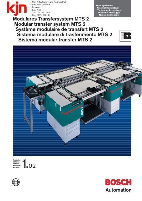
MontagetechnikAssembly technologyTechnique de montageTecnica di montaggioTécnica de montajeModulares Transfersystem MTS 2Modular transfer system MTS 2Système modulaire de transfert MTS 2Sistema modulare di trasferimento MTS 2Sistema modular transfer MTS 2AusgabeVersionVersionVersioneVersión1. 02Automation
- Page 2 and 3: 0-2SymboleSymbolsSymbolesSimboliSí
- Page 4 and 5: 0-4LM 2/NLM 2/HQM 2/ALM 2/HAKM 2/18
- Page 6 and 7: 1-0 MTS 2Das Modulare Transfer Syst
- Page 8 and 9: 1-2 MTS 2yMTS 2-Anlagen überzeugen
- Page 10 and 11: 2-0 WT 2/…Werkstückträger WT 2/
- Page 12 and 13: 3-0 QM 2/…Quertransportmodule QM
- Page 14 and 15: 3-2 QM 2/…Quertransportmodule QM
- Page 16 and 17: 3-4 QM 2/…Quertransportmodule QM
- Page 18 and 19: 3-6 QM 2/…Quertransportmodule QM
- Page 20 and 21: 3-8 UG 2/…Untergestelle UG 2/…B
- Page 22 and 23: 3-10 LM 2/…Längstransportmodule
- Page 24 and 25: 3-12 LM 2/H…Längstransportmodule
- Page 26 and 27: 4-0 KM 2/180Kurvenmodul KM 2/180Cur
- Page 28 and 29: 5-0Zentrale EnergieeinspeisungCentr
- Page 30 and 31: 5-2WT-DurchlaufsteuerungWorkpiece p
- Page 32 and 33: 5-4Montageleittechnik MLTAssembly c
- Page 34 and 35: 5-6IECsoftIECsoftIECsoftIECsoftIECs
- Page 36 and 37: 6-0Bestellbeispiel 1Ordering exampl
- Page 38 and 39: 6-2Bestellbeispiel 3Ordering exampl
- Page 40 and 41: 6-4Berechnung L HE , L HACalculatio
- Page 42 and 43: 7-0 WT 2/…Maße und technische Da
- Page 44 and 45: 7-2 QM 2/EQuertransportmoduleTransv
- Page 46 and 47: 7-4 UG 2/…UntergestelleBasesBâti
- Page 48 and 49: 3 842 999 716BBB*LLLL*L1L*M*VV*UUU/
- Page 50 and 51: 7-8 LM 2/HELängstransportmodul LM
MontagetechnikAssembly technologyTechnique de montageTecnica di montaggioTécnica de montaje<strong><strong>Modular</strong>es</strong> <strong>Transfer<strong>system</strong></strong> <strong>MTS</strong> 2<strong>Modular</strong> <strong>transfer</strong> <strong>system</strong> <strong>MTS</strong> 2Système modulaire de <strong>transfer</strong>t <strong>MTS</strong> 2Sistema modulare di trasferimento <strong>MTS</strong> 2Sistema modular <strong>transfer</strong> <strong>MTS</strong> 2AusgabeVersionVersionVersioneVersión1. 02Automation
0-2SymboleSymbolsSymbolesSimboliSímbolosWerkstückträger – EigengewichtWorkpiece pallet – empty weightPalette porte-pièces – poids à videPallet – peso proprioPortapiezas – peso proprioWerkstückträger – GesamtgewichtWorkpiece pallet – total weightPalette porte-pièces – poids totalPallet – peso totalePortapiezas – peso totalESDESD-fähigESD-capableAussi pour ESDAnche per ESDApto ESDF2 5-8Verweis zu einer anderen Seite oder zu einer ProduktübersichtReference to another page or a product overviewRenvoi à une autre page ou à une vue d'ensemble des produitsRinvio ad un'altra pagina o ad una descrizione del prodottoReferencia a otra hoja o a un resumen de productoTransportrichtungDirection of transportSens de transportDirezione di trasportoDirección de transporteOberkante TransportebeneTop surface of transport levelBord superiéur du niveau de transportSpigole superiore di livello di trasportoBorde superior de nivel de transportev = 12 m/minFördergeschwindigkeitConveying speedVitesse de transportVelocità di trasportoVelocidad de transporte3 842 999 780B = ___________ mmv = ___________ mmBestellnummer mit zusätzlich anzugebenden ParameternPart number with additionally required parametersN° de référence avec les paramètres à donner en plusCodice d’ordine con parametri supplementari da indicareNúmero de pedido con los parámetros adicionales y indicar
0-3Systemübersicht <strong>MTS</strong> 2System overview of <strong>MTS</strong> 2Vue d’ensemble du système <strong>MTS</strong> 2Panoramica del sistema <strong>MTS</strong> 2Resumen del sistema <strong>MTS</strong> 2WT 2/… QM 2/A QM 2/MF2 2-0F2 3-0F2 3-0QM 2/E UG 2/… LM 2/…F2 3-0F2 3-8F2 3-10KM 2/180Anlage Anlage Netz DruckluftyWT-DurchlaufsteuerungyyWorkpiece pallet pass-throughcontrolyyyCommande du parcours de lapalette porte-pièceyyyyComando del passaggio deipalletyyyyyControl de paso del portapiezasF2 4-0 F2 5-0 F2 5-1
0-4LM 2/NLM 2/HQM 2/ALM 2/HAKM 2/180QM 2/ELM 2/HEUG 2/…QM 2/MQM 2/EUG 2/…UG 2/…QM 2/MLM 2/HLM 2/NQM 2/AKM 2/180UG 2/…yNur wenige, in sich voll funktionsfähigeModule, bilden das <strong>Modular</strong>eTransfer System <strong>MTS</strong>2yyOnly a few fully functional modulesmake up the <strong>MTS</strong>2 modular <strong>transfer</strong><strong>system</strong>yyyLe système modulaire de <strong>transfer</strong>t<strong>MTS</strong>2 est composé de quelquesmodules entièrement autonomesyyyyIl sistema di trasferimento modulare<strong>MTS</strong> 2 é costituito solo da pochimoduli in sé pienamente funzionantiyyyyySólo unos pocos módulos defuncionamiento totalmenteindependiente componen el sistemamodular <strong>transfer</strong> <strong>MTS</strong>2
0-5InhaltContentsSommaireIndiceContenidoSystembeschreibungSystem descriptionDescription du systèmeDescrizione del sistemaDescripción del sistemaWerkstückträgerWorkpiece palletsPalettes porte-piècesPalletPortapiezasModule für taktunabhängige ArbeitsplätzeModules for clock-independent workplacesModules pour les postes de travail ne dépendant pas de la cadenceModuli per posti di lavoro indipendenti dalla cadenzaMódulos para puestos de trabajo independientes de la cadenciaKurvenmodulCurve moduleModule de courbeModulo curvaMódulo de curvaZubehörAccessoriesAccessoiresAccessoriAccesoriosBestellbeispiele und SystemmaßeOrder examples and <strong>system</strong> dimensionsModèles de commande et cotes du systèmeEsempi d'ordine e dimensioni del sistemaEjemplos de pedido y dimensiones del sistemaTechnische DatenTechnical dataCaractéristiques techniquesDati tecniciDatos técnicosWeitere Dokumentation zu <strong>MTS</strong> 2Further documentation concerning <strong>MTS</strong> 2Documentation complémentaire sur le <strong>MTS</strong> 2Documentazione supplementare sul <strong>MTS</strong> 2Referencia a documentación adicional para <strong>MTS</strong> 212345678
1-0 <strong>MTS</strong> 2Das <strong>Modular</strong>e Transfer System <strong>MTS</strong> 2The modular <strong>transfer</strong> <strong>system</strong> <strong>MTS</strong> 2Le système modulaire de <strong>transfer</strong>t <strong>MTS</strong> 2Il sistema modulare di trasferimento <strong>MTS</strong> 2El sistema modular <strong>transfer</strong> <strong>MTS</strong> 2yDas modulare <strong>Transfer<strong>system</strong></strong> <strong>MTS</strong> 2wird aus nur wenigen Modulen aufgebaut.Jedes dieser Module ist eine vollfunktionsfähige Einheit und enthält allefür seine Funktion erforderlichen Komponenten:Mechanik, Steuerung, Elektro-und Pneumatik-Installation. JedesModul wird vor der Auslieferung komplettgetestet.yyThe modular <strong>transfer</strong> <strong>system</strong> <strong>MTS</strong> 2 isconstructed out of only a fewmodules. Each of these modules is afully functional unit and contains allcomponents required for its function:mechanism, control, electric andpneumatic installation. Each module isfully tested prior to shipping.yyyLe système modulaire de <strong>transfer</strong>t<strong>MTS</strong> 2 ne comprend que quelquesmodules. Chacun de ces modules estune unité à part entière et dispose detous les composants nécessaires àson fonctionnement: mécanique,commande, installation électrique etpneumatique. Chaque module esttesté dans son intégralité avant d’êtrelivré.yyyyIl sistema modulare di trasferimento<strong>MTS</strong> 2 non è costituito che da pochimoduli. Ognuno di questi moduli èun’unità pienamente funzionante econtiene tutti i componenti necessarialla sua funzione: meccanica,comando, installazione elettrica epneumatica. Ogni modulo vienecompletamente sottoposto a test primadella consegna.yyyyyEl sistema modular <strong>transfer</strong> <strong>MTS</strong> 2 secompone tan sólo de unos pocosmódulos. Cada uno de estos móduloses una unidad independiente ycontiene todos los componentesnecesarios para su funcionamiento:mecánica, control e instalacióneléctrica y neumática. Cada móduloes verificado completamente antes desu envío.<strong>MTS</strong>2.TIF
<strong>MTS</strong> 2 1-1yDurch das neue Konzept ergibt sichein Zeitgewinn bei Planung, Inbetriebnahmeund Produktion:Planung innerhalb kürzester Zeit;Aufbau und Installation dank steckfertigerModule schnell, sicher undproblemlos; Flexibel in der Produktiondurch einfache Veränderbarkeit derUmlaufstrategie und des Anlagen-Layouts.yyThrough the new concept time issaved on planning, starting operationsand production:Planning within the shortest timepossible; Assembly and installation isfast, safe and problem-free thanks toready-to-plug modules; Flexible inproduction by means of simplechangeability of the circuit strategyand the layout of the <strong>system</strong>.yyyCe nouveau concept fait gagner dutemps pendant la conception, la miseen service et la production:la conception en un rien de temp;le montage et l’installation vite et biengrâce à des modules enfichables;d’une grande flexibilité dans laproduction grâce à un circuit et à uneinstallation simples à modifier.yyyyQuesta nuova concezione consente diguadagnare tempo in fase dipianificazione, messa in funzione eproduzione:la pianificazione avviene in un tempobrevissimo; il montaggio el’installazione si presentano veloci,sicuri e senza problemi grazie aimoduli pronti per l’innesto;la produzione è flessibile in quanto èpossibile modificare facilmente lastrategia del circuito e la disposizionedell’impianto.238.TIFyyyyyEste nuevo concepto permite ganartiempo en la planificación, puesta enfuncionamiento y producción:Planificación en el tiempo más cortoposible; Montaje e instalación rápidos,seguros y sin problemas gracias a losmódulos enchufables;Flexibilidad en la producción gracias aun circuito y una instalación fáciles demodificar.237.TIF1234567239.TIF240.TIF8
1-2 <strong>MTS</strong> 2y<strong>MTS</strong> 2-Anlagen überzeugen nicht nurdurch ihr neues, ansprechendes Design,sondern auch durch komfortableBedien-und Anzeigefunktionen, welcheSteuerungsentscheidungen vor Ortermöglichen. Das dezentrale Steuerungskonzept,verbunden mit demwerkstücksynchronen Datenfluss ergebenein Höchstmaß an Datensicherheit.<strong>MTS</strong> 2-Anlagen bieten darüberhinaus die Flexibilität für eine leichteErweiterbarkeit entsprechend IhrenFertigungsanforderungen.Ganz gleich, ob Sie zusätzlicheAnwendereingänge auswerten undAusgänge setzen wollen, eine Automatikstationeinbinden oder mit einemLeitrechner kommunizieren wollen:Die Steuerung des <strong>MTS</strong> 2 bietet dazugenügend Leistungsreserven.yy<strong>MTS</strong> 2 <strong>system</strong>s will not only convinceyou on account of their new, attractivedesign, but also through comfortableoperating and display functions whichenable control decisions to be takenon the spot. The decentralized controlconcept, in conjunction with theworkpiece-synchronous data flowprovide the highest level of datasecurity. Moreover, <strong>MTS</strong> 2 <strong>system</strong>sprovide the flexibility for simpleextensibility in accordance with yourmanufacturing requirements.It doesn’t matter whether you want toevaluate extra user inputs, set outputs,include an automatic station orcommunicate with a host computer,the <strong>MTS</strong> 2 controller provides enoughperformance reserves.yyyLes installations <strong>MTS</strong> 2 sont convaincantesnon seulement de par leurnouvelle esthétique attrayante maisaussi par leurs fonctions decommande et d’affichage confortablespermettant de commander directementsur place. La décentralisation duconcept de commande conjugué à lacirculation des données synchroniséeavec la palette donnent un maximumde sécurité à vos données. Lesinstallations <strong>MTS</strong> 2 sont en outresuffisamment flexibles pour êtrefacilement agrandies suivant lesexigences imposées à la production.Que vous désiriez évaluer des entréesutilisateur et mettre des sortiessupplémentaires, incorporer unestation automatique ou communiqueravec un ordinateur central, lacommande du <strong>MTS</strong> 2 a pour celasuffisamment de réserves.yyyyGli impianti <strong>MTS</strong> 2 sono convincentinon solo per il loro nuovo e attraentedesign, ma anche per le comodefunzioni di comando e visualizzazioneche permettono di comandare adistanza. La concezione del comandodecentralizzato e il flusso di datisincronizzato con il pallet offrono lamassima sicurezza ai dati. Gli impianti<strong>MTS</strong> 2 sono inoltre flessibili, nel sensoche si prestano facilmente ad essereampliati a seconda delle esigenzedella produzione.Sia che vogliate utilizzare entratedell’utente e installare uscitesupplementari, collegare una stazioneautomatica o comunicare con uncomputer centrale, il comandodell’<strong>MTS</strong> 2 presenta sempreprestazioni adeguate.yyyyyLas instalaciones <strong>MTS</strong> 2 convencenno sólo por su diseño atrayente, sinotam-bién por sus funciones decomando y visualización, que permitentomar decisiones de controldirectamente en el lugar. El conceptode mando descentralizado, unido alflujo de datos sincrónico con laspiezas, dan un máximo de seguridadde los datos. Las instalaciones <strong>MTS</strong> 2ofrecen además flexibilidad para unaampliación sencilla en función de susexigencias de fabricación.Tanto si usted desea evaluar entradasde usuario e instalar salidasadicionales, o incorporar una estaciónautomática, como si deseacomunicarse con un ordenadorcentral, el control del <strong>MTS</strong> 2 tienepara ello suficientes reservas.
<strong>MTS</strong> 2 1-3yAufbau und Inbetriebnahme einer<strong>MTS</strong> 2-Anlage erfolgen nach demPrinzip „Plug and Run“. Dies garantierteine kurze Zeitspanne bis zur Produktionsbereitschaft.Durch die Wiederverwendbarkeitjedes unserer Moduleohne Zerlegung in Einzelteile könnenSie Ihre Investition langfristig zu 100 %nutzen.yyAssembly and start-up of an <strong>MTS</strong> 2<strong>system</strong> take place according to the"Plug and Run" principle. Thisguarantees a short time period beforeit is ready for production. Through there-usability of each of our moduleswithout dismantling into single partsyou can make 100 % use of yourinvestment in the long-term.yyyLe montage et la mise en serviced’une installation <strong>MTS</strong> 2 sonteffectués selon le principe du "Plugand Run". Il y a ainsi un bref intervallejusqu’à ce qu’elle soit prête àproduire. Étant donné que chacun denos modules est réutilisable sans êtredémonté en plusieurs piècesdétachées, vous pouvez, à long terme,tirer profit à 100 % de votreinvestissement.12yyyyIl montaggio e la messa in funzione diun impianto <strong>MTS</strong> 2 avvengonosecondo il principio del "Plug andRun". Ciò garantisce che l’impianto siapronto per la produzione in pocotempo. Ogni modulo è riutilizzabilesenza che sia necessario scomporlo inparti singole ed è quindi possibile, alungo termine, trarre profitto al 100 %del proprio investimento.yyyyyEl montaje y la puesta enfuncionamiento de una instalación<strong>MTS</strong> 2 se llevan a cabo según elprincipio "Plug and Run". Ellogarantiza que la instalación esté listapara la producción en poco tiempo.Cada uno de nuestros módulos puedevolver a utilizarse sin necesidad dedesarmarlo en piezas componentes,de modo que usted puede utilizar suinversión al 100 % a largo plazo.34567VMP0996D.EPS8
2-0 WT 2/…Werkstückträger WT 2/…Workpiece palletsPalettes porte-piècesPalletPortapiezasyDer Werkstückträger WT 2/… dientzur Aufnahme des zu bearbeitendenWerkstücks sowie eines DatenträgersMDT. Dort werden werkstückbezogeneDaten (bis 8 kB) wie z. B.Identnummern, Fertigungszuständeund Fahrpläne gespeichert. Die Informationenkönnen über Schreib-Lese-Köpfe werkstücksynchron beliebig oftausgelesen oder überschrieben werden.Umfangreiche Sicherungsmechanismengarantieren ein Höchstmaßan Datensicherheit.Lieferumfang: Werkstückträger unmontiert,Mobiler Datenträger MDT8Kund Befestigungsmaterial.Hinweis: Die Befestigungsbohrungenfür den Datenträger sind kundenseitsanzubringen.yyThe workpiece pallet WT 2/… is forcarrying the workpiece to beprocessed and a data tag MDT.Here, workpiece-related data (up to8kB) such as ID numbers, state ofmanufacture and route plan arestored. The information can be readout or overwritten using read-writeheads synchronously with theworkpiece as often as desired.Extensive safety mechanismsguarantee a high degree of datasecurity.Scope of delivery: unmounted workpiecepallet, mobile data tag MDT8Kand fastening material.Note: The fastening bore holes for thedata tag must be made by thecustomer.yyyLa palette porte-pièces WT 2/… sertà recevoir la pièce à usiner et unsupport de données MDT. C’est làque sont mémorisées les données dela pièce (jusqu’à 8 kB) comme parexemple les numéros d’identification,les stades de fabrication et leshoraires. Les informations peuventêtre lues et réécrites avec les têtes delecture et d’écriture, ensynchronisation avec la pièce, autantde fois qu’on le désire. De nombreuxmécanismes garantissent un maximumde sécurité pour vos données.Fournitures: palette porte-pièce nonmontée, support mobile de donnéesMDT8K et matériel de fixation.Remarque: les alésages de fixationpour le support de données sont àeffectuer par le client.yyyyIl pallet WT 2/… serve ad accogliere ilpezzo da lavorare e un supporto datiMDT, su cui vengono memorizzatidati relativi al pezzo (fino a 8kB) comead es. numeri di identificazione, statodella produzione e orari. Attraversotestine di lettura e scrittura, leinformazioni possono essere lette emodificate, in sincronia con il pezzo,tutte le volte che lo si desidera.Numerosi meccanismi di sicurezzagarantiscono la massima sicurezza aidati.Fornitura: pallet non montato,supporto dati mobile MDT8K emateriale di fissaggio.Avvertenza: i fori di fissaggio per ilsupporto dati devono essere effettuatidal cliente.yyyyyEl portapiezas WT 2/… sirve pararecibir a las piezas a maquinar y a unsoporte de datos MDT. Allí sealmacenan datos relacionados con laspiezas (hasta 8 kB) como ser porejemplo, números de identificación,estados de fabricación y horarios.Estas informaciones pueden ser leídaso sobrescritas cuantas veces sedesée mediante las cabezas deescritura-lectura, sincrónicamente conlas piezas. Numerosos mecanismosde seguridad garantizan una máximaseguridad para los datos.Volumen del suministro: portapiezassin montar, soporte de datos móvilMDT8K y material de fijación.Indicación: Las perforaciones defijación para el soporte de datosdeben ser realizadas por el cliente.Maße und weitere Angaben F2 7-0Dimensions and otherinformation F2 7-0Cotes et autres données F2 7-0Dimensioni ed altri dati F2 7-0Medidas y otros datos F2 7-0
WT 2/… 2-1y Mobiler Datenträger MDTyyMobile data tagyyySupport mobile de donnéesyyyySupporto dati mobileyyyyySoporte de datos móvilyMontagesockelyyAssembly baseyyySocle de montageyyyyZoccolo di montaggioyyyyyBase de montaje123WTA.EPSyRahmenmoduleyyFrame modulesyyyModules de cadreyyyyModuli di telaioyyyyyMódulos de bastidoryTrägerplatteyyCarrying plateyyyPlaque-supportyyyyPiastra di supportoyyyyyPlaca portadorayPositionierbuchsenyyPositioning bushesyyyDouilles de positionnementyyyyBoccole di posizionamentoyyyyyCasquillos de posicionam45WT 2/… I WT x b WT [kg] F [kg][mm] [mm]160 160 x 160 1,2 6 3 842 521 315240 240 x 240 2,6 8 3 842 521 316320 320 x 320 4,4 10 3 842 521 317678
3-0 QM 2/…Quertransportmodule QM 2/…Transverse conveyor modulesModules de transport transversalModuli di trasporto trasversaleMódulos de transporte transversalyDie Quertransportmodule sind diezentralen Bausteine zum Aufbau desmodularen <strong>Transfer<strong>system</strong></strong>s. Sie dienenzum Verzweigen der Werkstückträgerin die taktunabhängigen Arbeitsplätze,die der Anlage die erforderlicheFlexibilität geben.Jedes Modul ist voll funktionsfähig undausgetestet. Das erleichtert die Inbetriebnahmeund stellt sicher, dassErweiterungen der Anlage jederzeitunproblematisch zu realisieren sind.yyThe transverse conveyor modulesare the central components forconstructing the modular <strong>transfer</strong><strong>system</strong>. They are for routing theworkpiece pallets to the clock-independentworkplaces which give theinstallation the required amount offlexibility.Each module is fully functional and hasbeen tested. That simplifies startingupand guarantees that extensions tothe installation can be realized at anytime without any problem.yyyyI moduli di trasporto trasversalecostituiscono il fondamento delsistema modulare di trasferimento.Servono a biforcare il percorso deipallet verso i posti di lavoroindipendenti dalla cadenza, chedonano la necessaria flessibilitàall’impianto.Ogni modulo è pienamentefunzionante e già sottoposto acontrollo. Ciò facilita la messa infunzione ed assicura la possibilità direalizzare in ogni momentoampliamenti dell’impianto senza alcunproblema.yyyyyLos módulos de transporte transversalson los componentes básicos delsistema <strong>transfer</strong> modular. Sirven parala bifurcación de los portapiezas haciapuestos de trabajo independientes dela cadencia que le dan a la instalaciónla flexibilidad necesaria. Cada móduloestá listo para funcionar y ha sidoverificado. Esto facilita la puesta enfuncionamiento y permite en todomomento ampliar la instalación sinproblemas.ByyyLes modules de transport transversalconstituent les pièces maîtresses pourconstruire le système de <strong>transfer</strong>tmodulaire. Elles servent à fairebifurquer la palette porte-pièce versdes postes qui ne dépendent pas dela cadence mais qui donnent àl’installation toute sa flexibilité.Chaquemodule est en complet état de marcheet a été testé. La mise en service enest ainsi facilitée et permet d’agrandirà tout moment l’installation sansaucune difficulté.QM2A.EPSy Ausschleusmodul QM 2/Ayy Outfeed moduleyyy Module de sortieyyyy Modulo di uscitayyyyy Módulo de salida
QM 2/… 3-112345y Einschleusmodul QM 2/Eyy Infeed moduleyyy Module d’entréeyyyy Modulo di ingressoyyyyy Módulo de entrada6y Mittenmodul QM 2/Myy Central moduleyyy Module centralyyyy Modulo centraleyyyyy Módulo central7Abmessungen F2 7-1…7-3Dimensions F2 7-1…7-3Dimensions F2 7-1…7-3Dimensioni F2 7-1…7-3Dimensiones F2 7-1…7-38
3-2 QM 2/…Quertransportmodule QM 2/…Transverse conveyor modulesModules de transport transversalModuli di trasporto trasversaleMódulos de transporte transversalyÜber einen Auszug sind alleSteuerungskomponenten im vorderenTeil jedes Quertransportmoduls leichtzugänglich. Hier befindet sich nebendem 24 V-Netzteil und dem Leistungsteilauch das <strong>MTS</strong> 2-Steuergerät – dieSchalt- und Kommunikationszentraleder Module. Über zwei Schreib-Lese-Köpfe wertet es die Informationen ausden mobilen Datenträgern aus undsteuert den Werkstückträgerfluss entsprechend.Die hierzu erforderlichenProgramme sind bereits serienmäßiginstalliert. Großzügige Leistungsreservenermöglichen E/A-Erweiterungenebenso wie die Kommunikation mit einerAutomatikstation über eine serielleSchnittstelle gemäß Industriestandard.Alle Sensoren und Schaltelementesind über das Aktuator-Sensor-Interface(AS-I) mit dem Steuergerät verbunden,wodurch sich auch applikationsspezifischeErweiterungen mit einemMinimum an Verdrahtungsaufwandrealisieren lassen.Ein <strong>system</strong>weites Datennetzwerk sorgtfür die Verständigung der Moduleuntereinander sowie für den Anschlusseines optionalen Leitrechners.yyBy means of a pull-out, all controlcomponents are easily accessible inthe front part of each transverseconveyor module. Here, beside the24 V power supply and the mainsupply there is the <strong>MTS</strong> 2 controldevice – the central switching andcommunication unit of the modules.Via two read-write heads it evaluatesthe information from the mobile datatags and controls the flow of theworkpiece pallets on the basis of it.The programs required for this arealready standardly installed. Generousreserves of performance enable I/Oexpansion as well as the communicationwith an automatic station via aserial interface in accordance with theindustrial standard. All sensors andswitching elements are connected tothe control device via the actuatorsensor-interface(AS-I), so that evenapplication-specific extensions can berealized with a minimum of wiring.A <strong>system</strong>-wide data network providesfor communication among themodules as well as for connecting toan optional host computer.yyyGrâce à un tiroir, tous les composantsde commande sont facilementaccessibles dans la partie avant dechaque module de transport transversal.C’est ici que se trouvent enplus du bloc d’alimentation 24 V et dumoteur, l’appareil de commande<strong>MTS</strong> 2, la centrale de commutation etde communication des modules. Ilévalue les informations des supportsmobiles de données par les deux têtesde lecture et d’écriture et commandeen conséquence le flux des palettesporte-pièces. Les programmesnécessaires sont installés en série.Grâce à l’énorme puissance qu’il a enréserve, il permet des extensions E/Sainsi que de communiquer avec unestation automatique par une interfacesérielle conformément aux standardsindustriels. Tous les capteurs et leséléments de commutation sont reliés àl’appareil de commande par uneinterface actuateur-senseur (AS-I)permettant ainsi d’agrandiry1 Steuerungseinbauten in SchutzartIP 542 Der Schreib-Lese-Kopf SLK liestInformationen aus dem Datenträgerdes Werkstückträgers und übermitteltsie an die Steuerung3 Längstransportmodule LM 2 undKurvenmodule KM 2 werden einfach invorbereitete Aufnahmen eingehängt4 Steckanschlüsse für Elektrik,Pneumatik und Netzwerk ermöglichendie schnelle Installationyy1 Built-in control units conforming tosafety norm IP 542 The read-write head SLK readsinformation from the data tag of theworkpiece pallet and transmits it to thecontroller3 Longitudinal conveyor modules LM 2and curve modules KM 2 are simplyhung in prepared holding fixtures4 Plug connections for electric,pneumatic and network parts enablerapid installationFigur-29.EPS
QM 2/… 3-3SYSA1.EPSl’installation pour une applicationspécifique avec un minimum de travail.Un réseau informatique de donnéesdans tout le système permet de fairecommuniquer les modules entre eux etd’y relier un ordinateur centralsupplémentaire.yyyyGrazie ad un cassetto, sono facilmenteaccessibili tutti i componenti dellaparte anteriore di ciascun modulo ditrasporto trasversale. Qui si trova oltreall’alimentatore a 24V e all’unità dipotenza, anche l’apparecchio dicomando <strong>MTS</strong> 2, che costituisce lacentrale di commutazione ecomunicazione dei moduli. Attraversodue testine di lettura e scrittura, essovaluta le informazioni dei supporti datimobili e regola corrispondentemente ilflusso dei pallet. I programmi necessarisono già installati di serie. Le enormipotenzialità consentono di ampliare leE/U e la comunicazione con unastazione automatica tramiteun’interfaccia seriale conforme allostandard industriale. Tutti i sensori e icommutatori sono collegatiall’apparecchio di comando tramitel’interfaccia attuatore-sensore (AS-I),che consente di realizzare ampliamentiper applicazioni specifiche con uncablaggio minimo.Una rete informatica di dati capace dicoprire l’intero sistema realizza lacomunicazione tra i moduli e ilcollegamento ad un computer centraleopzionale.yyyyyPor medio de un cajón puedeaccederse fácilmente a todos loscomponentes de control en la partedelantera de cada módulo de transportetransversal. Allí se encuentra, al ladode la unidad de alimentación de 24V yde la unidad de potencia, el aparatode mando del <strong>MTS</strong> 2 - los módulos deconmutación y de comunicación. Pormedio de dos cabezas de escrituralecturael módulo evalúa lasinformaciones de los soportes dedatos móviles y comanda enconsecuencia al flujo de portapiezas.Los programas necesarios ya estáninstalados en serie. Generosasreservas de rendimiento permitenampliaciones de E/S, así comotambién la comunicación con unaestación automática a través de uninterface serial según los estándaresindustriales. Todos los sensores y loselementos de conmutación estánconectados con el aparato de mandopor medio del interface actuadorsensor(AS-I), con lo cual tambiénpueden llevarse a cabo ampliacionesen función de las aplicaciones con unmínimo de cables.Una red informática de datos en toboel sistema se ocupa de lacomunicación entre los módulos ypermite la conexión de un ordenadorcentral opcional.yyyy1 Installazione di sistemi di comando contipo di protezione IP 542 La testina di lettura e scrittura SLKlegge le informazioni del supporto datidel pallet e le trasmette al comando3 I moduli di trasporto longitudinale LM 2e i moduli curva KM 2 vengono appesisemplicemente agli alloggiamentiprevisti4 I raccordi ad innesto consentono direalizzare installazioni elettriche,pneumatiche e informatiche veloci123456yyy1 Installation de systèmes de commandeen type de IP 542 La tête de lecture-écriture SLK lit lesinformations du support de données dela palette porte-pièces et les transmet àla commande3 Les modules de transport transversalLM 2 et les modules de courbe KM 2sont accrochés simplement dans leslogements prévus4 Les raccords mâles pour l’électricité, lesystème pneumatique et le réseauinformatique accélèrent l’installationyyyyy1 Instalación de sistemas de comando entipo de protección IP 542 La cabeza de escritura-lectura SLK leeinformaciones proveniente del soportede datos del portapiezas y lastransmite al control3 Los módulos de transporte longitudinalLM 2 y los módulos de curva KM 2 seinsertan simplemente en los lugaresprevistos4 Enchufes para la instalación eléctrica yneumática y para la red permiten unainstalación rápida78
3-4 QM 2/…Quertransportmodule QM 2/…Transverse conveyor modulesModules de transport transversalModuli di trasporto trasversaleMódulos de transporte transversalyDas Bedienfeld ist Anzeigeelementund Eingabegerät gleichzeitig! Aufeiner LCD-Anzeige und durch LEDserhält das Bedienpersonal ständigInformationen über Werkstückdaten,Systemzustände oder Fehlermeldungen.Ohne spezielles steuerungstechnischesKnow-how parametriertdas Bedienpersonal die Module amBedienfeld und legt damit den Werkstückträgerumlauffür die gesamteAnlage fest. Damit gelingen Inbetriebnahme,Umrüsten und Erweiterungeneiner <strong>MTS</strong> 2-Anlage in kürzester Zeit.yyThe control panel is both a displayelement and an input device! On anLCD-display and by means of LEDs theoperating personnel constantly receiveinformation about workpiece data,<strong>system</strong> states or error messages.Without any special expertise theoperating personnel can parametrizethe modules at the control panel andthus define the circuit of the workpiecepallets for the entire installation.This means that start-up, conversionand extension of an <strong>MTS</strong> 2 installationcan be conducted successfully in theshortest possible time.yyyLe panneau de commande fait officeen même temps d’élément d’affichageet d’appareil d’opérations! Sur unaffichage à cristaux liquides et pardiode électroluminescente, lesutilisateurs reçoivent en permanencedes informations sur les données despièces, les statuts du système ou desmessages d’erreur.Sans disposer de connaissancesparticulières en matière de techniquede commande, l’utilisateur donne lesparamètres des modules sur lepanneau de commande et définit ainsile parcours de la palette porte-piécedans toute l’installation. La mise enservice d’une installation <strong>MTS</strong> 2, satransformation et son extension sontsûres de réussir en un rien detemps.yyyyIl pannello di comando ècontemporaneamente elemento divisualizzazione e apparecchio pereffettuare introduzioni di dati! TramiteLED e un display LCD, il personale diservizio ottiene informazioni costantisullo dati relativi ai pallet, stato delsistema o messaggi di errore.Senza particolare know-how tecnicodi comando, il personale di serviziointroduce i parametri dei moduli sulpannello di comando, stabilendo in talmodo il circuito dei pallet per l’interoimpianto. Ciò consente la messa infunzione, la trasformazione el’ampliamento di un impianto <strong>MTS</strong> 2 inbrevissimo tempo.yyyyy¡El panel de comando es a la vezelemento de visualización y aparato deintroducción de operaciones! A travésde una pantalla LCD y de LEDs, losoperadores reciben permanentementeinformaciones sobre datos de piezas,los estados del sistema o mensajesde error.Sin tener conocimientos especialessobre técnicas de comando, losoperadores introducen los parámetrosde los módulos en el panel decomando y definen así el recorrido delportapiezas en toda la instalación. Deeste modo, la puesta en funcionamiento,las modificaciones yampliaciones de una instalación<strong>MTS</strong> 2 se llevan a cabo en el menortiempo posible.12
QM 2/… 3-5SYSA1.EPS3y1 Umfangreiche Diagnosefunktionengeben wichtige Informationen über denZustand der Anlage2 Unmissverständlich: Klarsicht-LCD-Anzeige des Bedienfeldes3 Über die Tastatur wird der Werkstückträger-Umlaufpasswortgeschützt durchdie gesamte Anlage parametriert4 LEDs zeigen den Anlagenstatusoptisch an5 Jeder Arbeitsplatz kann einzeln nachBedarf an- oder abgeschaltet werden45yy1 Extensive diagnostic functions provideimportant information about the state ofthe installation2 Unambiguous: clear LCD display of thecontrol panel3 Via the keyboard the workpiece palletroute through the entire installation isparametrized with password protection4 LED’s show the status of theinstallation in visual form5 Each workplace can be switched on oroff as necessaryyyy1 De nombreuses fonctions dediagnostic donnent des informationsimportantes sur le statut del’installation2 Clair et net: l’affichage clair à cristauxliquides du panneau de commande3 Les paramètres de la palette portepiècesont donnés par clavier pour toutle circuit et sont protégés par mot depasse4 Les DEL visualisent le statut del’installation5 Chaque poste de travail peut être misen route ou être arrêté individuellementsuivant les besoinsyyyy1 Numerose funzioni di diagnosiforniscono informazioni importanti sullostato dell’impianto2 Niente malintesi: chiaro visualizzatore adiodi LCD del pannello di comando3 Attraverso la tastiera si inseriscono iparametri relativi al circuito dei palletche vengono protetti tramite una parolad’ordine4 Lo stato dell’impianto viene visualizzatotramite LED5 Ogni posto di lavoro può esserecollegato o isolato singolarmente aseconda delle necessità12345yyyyy1 Numerosas funciones de diagnósticodan informaciones importantes sobre elestado de la instalación2 Claridad: pantalla LCD claro del panelde comando3 Los parámetros del portapiezas seintroducen por medio del teclado paratodo el circuito y están protegidos conuna contraseña4 Los LED muestran el estado de lainstalación5 Cada puesto de trabajo puede serincorporado al circuito o anuladoindividualmente según las necesidades678BEDIEN.EPS
3-6 QM 2/…Quertransportmodule QM 2/…Transverse conveyor modulesModules de transport transversalModuli di trasporto trasversaleMódulos de transporte transversalyEntsprechend ihrer Aufgabe enthaltendie Quertransportmodule allesinclusive:l die gesamte Elektro- undPneumatik-Installationl Steuergerät zur Auswertung derWerkstück-Informationen, Steuerndes Werkstückträger-Umlaufs undzum Datenaustausch mit Maschinensteuerungenl Bedienfeld zur Anzeige von Informationenim Klartext und zur Parametrierungdes Werkstückträger-Umlaufsl Netzwerk zur Kommunikation derQuertransportmodule untereinanderund zum Anschluss eines optionalenLeitrechnersGehäuse: Stahlblech, pulverbeschichtet,leitfähigFarbe: Wasserblau (RAL5021)Lichtgrau (RAL 7035) fürAbdeckungenLieferumfang: Quertransport komplettmontiert, vorbereitet für die Montageauf dem Untergestell. Bei QM 2/A undQM 2/M: Zusätzlich noch zweiSchreib-Lese-Köpfe (SLK) als Beilage.yyIn accordance with their task thetransverse conveyor modules containeverything inclusively:l the entire electric and pneumaticinstallationl control device for evaluating theworkpiece information, controllingthe workpiece pallet route and fordata exchange with machinecontrollersl control panel for displayinginformation in textual form and forparametrizing the workpiece palletroutel network for communication amongthe transverse conveyor modulesand for connecting an optional hostcomputerHousing: sheet-steel, powder-coated,conductingColor: clear-blue (RAL 5021)Light grey (RAL 7035) for CoverScope of delivery: Transverseconveyor completely assembled andset up for mounting on the frame base.Two additional read/write heads(SLK) included with the QM 2/A andQM 2/M modules.yyyPour remplir leur tâche, les modulesde transport transversal comprennenttout inclus:l la totalité de l’installation électriqueet pneumatiquel l’appareil de commande pourl’évaluation des informations de lapièce, pour commander le parcoursde la palette porte-pièce et pouréchanger des données avec lescommandes des machinesl Le panneau de commande pourafficher les informations au clair etpour donner les paramètres duparcours de la palette porte-piècel Réseau informatique pour lacommunication des modules detransport transversal entre eux etpour y brancher un ordinateursupplémentaireCarter: tôle d’acier, revêtement àpoudre, conducteurColoris: bleu clair (RAL 5021)Gris clair (RAL 7035) pourrecouvrementFournitures: Bandes transversalesentièrement montées, préparées pourle montage sur le bâti inférieur. Sur lesQM 2/A et QM 2/M: deux têtes delecture-écriture (SLK) supplémentaires.Abmessungen F2 7-1…7-3Dimensions F2 7-1…7-3Dimensions F2 7-1…7-3Dimensioni F2 7-1…7-3Dimensiones F2 7-1…7-3
QM 2/… 3-7SYSAA.EPSBQM 2/AQM 2/M QM 2/EyyyyA seconda dei Vostri compiti, i modulidi trasporto trasversale comprendono:l installazione elettrica e pneumaticacompletal apparecchio di comando per lavalutazione delle informazioni delpallet, il comando del circuito deipallet e lo scambio di dati con icomandi delle macchinel pannello di comando pervisualizzare le informazioni in testochiaro e per introdurre i parametridel circuito dei palletl rete informatica per lacomunicazione tra i pallet e ilcollegamento ad un computercetrale opzionaleScatola: lamiera d’acciaio,rivestimento a polvere, conduttoreColore: blu (RAL 5021)grigio (RAL 7035) per copertureFornitura: Trasporto trasversalecompletamente montato, pronto per ilmontaggio sull’intelaiatura di base. NelQM 2/A e nel QM 2/M sono compresedue testine di lettura-scrittura (SLK)supplementari.yyyyyDe acuerdo con la tarea a realizar, losmódulos de transporte transversalincluyen:l toda la instalación eléctrica yneumátical aparato de mando para evaluar lasinformaciones de los portapiezas,para comandar el recorrido de losportapiezas y para el intercambio dedatos con los comandos de lasmáquinas.l panel de comando para mostrarclaramente informaciones y paraintroducir los parámetros delrecorrido de los portapiezas.l red para la comunicación de losmódulos de transporte transversalentre sí y para la conexión a unordenador central opcionalCarcasa: chapa de acero,recubrimiento pulverizado, conductorColor: azul marino (RAL 5021)Gris claro (RAL 7035) pararecubrimientoVolumen del suministro: Transportetransversal completamente montado,preparado para el montaje sobre elarmazón inferior. En el caso de QM 2/A y QM 2/M: adicionalmente doscabezas de escritura-lectura (SLK)suplementarias.12345ESDWT 2/… B v ESD-fähig QM 2/A… QM 2/M… QM 2/E…[mm] [mm] [m/min] ESD-capableAussi pour ESDAnche per ESDApto ESD160 600 6 N = nicht leitfähig 3 842 999 753 3 842 999 751 3 842 999 7541000 9 non conductive B = ____ mm B = ____ mm B = ____ mm12 non conducteur v = ____ m/min v = ____ m/min v = ____ m/minnon conduttore ESD = ____ ESD = ____ ESD = ____no conductor240 600 6 A = antistatisch 3 842 999 780 3 842 999 755 3 842 999 7831000 9 antistatic B = ____ mm B = ____ mm B = ____ mm12 antistatique v = ____ m/min v = ____ m/min v = ____ m/minantistatico ESD = ____ ESD = ____ ESD = ____antiestático320 600 6 3 842 999 781 3 842 999 757 3 842 999 7841000 9 B = ____ mm B = ____ mm B = ____ mm12 v = ____ m/min v = ____ m/min v = ____ m/minESD = ____ ESD = ____ ESD = ____678
3-8 UG 2/…Untergestelle UG 2/…BasesBâtis inférieursIncastellature inferioriArmazones inferioresyDas attraktive Design der Quertransportmodulewird in Kombinationmit den abgestimmten Untergestellenbesonders hervorgehoben.Zwei Varianten:Mit drei Schubladen (UG 2/SL),mit einem Fachboden (UG 2/FB)bieten reichlich Raum für Ablage.Höhenverstellbare Füße erleichternIhnen das Ausrichten der Anlage.Gehäuse: Stahlblech, pulverbeschichtet,leitfähigFarbe: Lichtgrau (RAL 7035)yyThe attractive design of the transverseconveyor modules is especiallyemphasized in combination with thecoordinated bases.Two variants:with three drawers (UG 2/SL)with a shelf (UG 2/FB) provide plentyof space for resting objects. Heightadjustablefeet make it easier toposition the installation.Housing: sheet-steel, powder-coated,conductingColor: light grey (RAL 7035)yyyLe design attrayant des modules detransport transversal est toutparticulièrement souligné lorsqu’il estcombiné avec les bâtis inférieursharmonisés.Deux variantes:avec trois tiroirs (UG 2/SL)à case (UG 2/FB) vous offrentsuffisamment de place pour vosdocuments. Des pieds réglables enhauteur facilitent l’alignement del’installation.Carter: tôle d’acier, revêtement àpoudre, conducteurColoris: gris clair (RAL 7035)yyyyL’attraente design dei moduli per iltrasporto trasversale risaltaparticolarmente in combinazione conl’incastellatura inferiorecorrispondente.Due varianti:con tre cassetti (UG 2/SL)con un ripiano (UG 2/FB)offrono sufficiente spazio per ladocumentazione. Piedi regolabilifacilitano l’allineamento dell’impianto.Scatola: lamiera d’acciaio,rivestimento a polvere, conduttoreColore: grigio chiaro (RAL 7035)yyyyyEl diseño atractivo de los módulos detransporte transversal se resaltaespecialmente en combinación conlos armazones inferiorescorrespondientes.Dos variantes:con tres cajones (UG 2/SL)con un estante (UG 2/FB), ofrecensuficiente espacio. Las patasregulables en altura facilitan lanivelación de la instalaciónCarcasa: chapa de acero,revestimiento pulverizado, conductorColor: gris claro (RAL 7035)Abmessungen F2 7-4Dimensions F2 7-4Dimensions F2 7-4Dimensioni F2 7-4Dimensiones F2 7-4
UG 2/… 3-9UG 2/SL UG 2/FB123BG b WT Tischtiefe SL FBTable depthProfondeur de tableProfondità del tavoloProfundidad de la mesaBG1 160 600 3 842 522 110 3 842 522 111240 600 3 842 522 110 3 842 522 111BG2 160 1000 3 842 522 112 3 842 522 113240 1000 3 842 522 112 3 842 522 113320 600 3 842 522 112 3 842 522 113320 1000 3 842 522 112 3 842 522 113UG2-3D.EPS45678
3-10 LM 2/…Längstransportmodule LM 2/…Longitudinal conveyor modulesModules de transport longitudinalModuli di trasporto longitudinaleMódulos de transporte longitudinalyEinbau und Installation der LängstransportmoduleLM 2/N (Nebenstrecke)und LM 2/H (Hauptstecke)für die taktunabhängigen Arbeitsplätzeist denkbar einfach: Zwischen zweiQuertransportmodulen einhängen,Schrauben festziehen und Verbindungenfür elektrische und pneumatischeEnergie stecken – fertig!Lieferzustand: Die Längstransportmodulewerden komplett montiertgeliefert incl. einem Schreib-/LesekopfSLK. Zum Lieferumfang desLM 2/H gehört zusätzlich ein Kabelkanalmit Trennstegen und Befestigungsbügeln.Die Motoren sind mitsteckbaren Anschlusskabeln versehen.Hinweis: Für lichte Breiten A > 2,5 mwerden zur Stabilisierung zusätzlicheStreckenstützen SZ 2 (F TS 2plus-Katalog) mitgeliefert.LM 2/HyyInsertion and installation of the longitudinalconveyor modules LM 2/N(shunt) and LM 2/H (main section) forclock-independent workplaces isincredibly simple: hang them betweentwo transverse conveyor modules,twist the bolts tight and plug in theconnections for electric andpneumatic energy – finished!Condition on delivery: The longitudinalconveyor modules are deliveredcompletely assembled including anSLK read/write head. Included in thescope of delivery of the LM 2/H are acable duct with separating web andmounting brackets. The motors aresupplied with pluggable connectingcables.Note: For free widths where A > 2.5 m,additional SZ2 leg sets are suppliedfor stability (F TS 2plus catalog).LM 2/NyyyLe montage et l’installation desmodules longitudinaux LM 2/N (circuitdérivé) et LM 2/H (circuit principal)pour les postes de travail qui nedépendent pas de la cadence estvraiment tout simple: il suffit de lesaccrocher entre deux modules detransport transversal, de serrer les viset d’enfoncer les raccords d’énergieélectrique et pneumatique – et c’estfini !Etat à la livraison: Les modules detransport transversal sont livrésentièrement montés, une tête delecture-écriture SLK incluse. Unegoulotte de câbles à tige deséparation et des étriers de fixationsont compris dans les fournitures duLM 2/H. Les moteurs sont équipés decâbles de branchement enfichables.Remarque: Des supports de sectionsupplémentaires SZ 2 sont comprisdans les fournitures pour lastabilisation des largeurs intérieures(F catalogue TS 2plus).BS2H3DA.EPSBS2S3DA.EPSAbmessungen F2 7-5, 7-6Dimensions F2 7-5, 7-6Dimensions F2 7-5, 7-6Dimensioni F2 7-5, 7-6Dimensiones F2 7-5, 7-6
LM 2/… 3-11LM 2/HyyyyIl montaggio e l’installazione dei modulidi trasporto longitudinale LM 2/N(tratto secondario) e LM 2/H (trattoprincipale) per i posti di lavoroindipendenti dalla cadenza sonoveramente semplici: basta appenderlitra due moduli di trasporto trasversale,stringere le viti e infilare i raccordi perl’energia elettrica e pneumatica, ed èfatto!Stato alla consegna: I moduli ditrasporto longitudinali vengono forniticompletamente montati e sonocomprensivi di una testina di letturascrittura.Nella fornitura dell’LM 2/Hsono compresi anche un cunicolo percavi con traversino di separazione estaffe di fissaggio. I motori sonoprovvisti di cavi di collegamento aspina.Avvertenza: Per larghezze interneA > 2,5 m, vengono forniti ulteriorisupporti tratto SZ 2 che garantisconomaggiore stabilità (F catalogo TS 2plus).yyyyyEl montaje y la instalación de losmódulos de transporte longitudinalLM 2/N (tramos secundarios) undLM 2/H (tramo principal) parapuestos de trabajo independientes dela cadencia es muy sencillo: bastacolocarlos entre dos módulos detransporte transversal, ajustar los tornillosy enchufar las conexiones parala energía eléctrica y neumática y¡listo!Condición de entrega: Los módulosde transporte longitudinal se entregancompletamente montados, incluidauna cabeza de escritura-lectura SLK.En el volumen del suministro del LM 2/Hse incluyen además una canal decables con separadores y estribos defijacíon. Los motores están equipadoscon cables de conexión enchufables.Indicación: Para la estabilización deanchos interiores A > 2,5 m seentregan apoyos de tramo SZ 2adicionales (F catálogo TS 2plus).LM 2/NALM 2/NSYSDA.EPS1234ESDWT 2/… A v ESD-fähig LM 2/H… LM 2/N…[mm] [mm] [m/min] ESD-capableAussi pour ESDAnche per ESDApto ESD160 500 6 N = nicht leitfähig 3 842 999 750 3 842 999 749– 9 non conductive A = ____ mm A = ____ mm5000 12 non conducteur v = ____ m/min v = ____ m/minnon conduttore ESD = N/A ESD = N/Ano conductor240 500 6 A = antistatisch 3 842 999 771 3 842 999 774– 9 antistatic A = ____ mm A = ____ mm5000 12 antistatique v = ____ m/min v = ____ m/minantistatico ESD = N/A ESD = N/Aantiestático320 500 6 3 842 999 772 3 842 999 775– 9 A = ____ mm A = ____ mm5000 12 v = ____ m/min v = ____ m/minESD = N/AESD = N/A5678
3-12 LM 2/H…Längstransportmodule LM 2/H…Longitudinal conveyor modulesModules de transport longitudinalModuli di trasporto longitudinaleMódulos de transporte longitudinalLM 2/HE,yFür Anlagen-Layouts, die zwischenKurve und taktunabhängigem Arbeitsplatzeine Zwischenstrecke erforderlichmachen, werden zwei Längstransportmoduleangeboten:LM 2/HA, vorgesehen zwischenKurve und Ausschleusmodulvorgesehen zwischenEinschleusmodul undKurveBei Längstransportmodul-Längen> 2,5 m werden zusätzliche StreckenstützenSZ 2 mitgeliefert(F TS 2plus Katalog).Lieferumfang: Die LängstransportmoduleLM 2/HA und LM 2/HE werdenkomplett montiert geliefert. Einentsprechender Kabelkanal ist beigelegt.Die Motoren sind mit steckbarenAnschlusskabeln ausgestattet.yyFor <strong>system</strong> layouts which require anintermediate section between thecurve and the clock-independentworkplace, two longitudinal conveyormodules are provided:LM 2/HA, for use between curveLM 2/HE,and outfeed modulefor use between infeedmodule and curveAdditional SZ2 leg sets are suppliedwith longitudinal conveyor lengths> 2.5 m (F TS 2plus catalog). Thenecessary cable duct is supplied.Scope of delivery: The longitudinalconveyor modules LM 2/HA andLM 2/HE are delivered completelyassembled. A suitable cable duct isalso provided. The modules areequipped with pluggable connectingcables.yyyPour les types d’installation où unesection intermédiaire estindispensable entre la courbe et leposte de travail indépendant de lacadence, deux modules longitudinauxsont proposés:LM 2/HA, prévu entre la courbe etLM 2/HE,le module de sortieprévu entre le moduled’entrée et la courbePour les longueurs de moduleslongitudinaux > 2,5 m, des supportsde section supplémentaires SZ 2sont compris dans les fournitures(F catalogue TS 2plus).Fouritures: Les modules de transporttransversal LM 2/HA et LM 2/HE sontlivrés entièrement montés. Unegoulotte correspondante y est jointe.Les moteurs sont équipés de câblesde branchement enfichables.LM 2/HELM 2/HABS2VEA.EPSLM2HA3DA.EPSAbmessungen F2 7-7, 7-8Dimensions F2 7-7, 7-8Dimensions F2 7-7, 7-8Dimensioni F2 7-7, 7-8Dimensiones F2 7-7, 7-8
LM 2/H… 3-13LLLM 2/HALM 2/HEyyyyPer i tipi di impianto in cui sianecessario un tratto intermedio tra lacurva e il posto di lavoro indipendentedalla cadenza, vengono proposti duemoduli di trasporto longitudinale:LM 2/HA, tra la curva e il modulo diLM 2/HE,uscitatra il modulo di ingresso ela curvaPer moduli di trasporto longitudinalidi lunghezza > 2,5 m, vengono fornitiulteriori supporti tratto SZ 2(F catalogo TS 2plus).yyyyyPara instalaciones que requieren untramo intermedio entre la curva y elpuesto de trabajo independiente de lacadencia existen dos módulos detransporte longitudinal:LM 2/HA, previsto entre la curva yLM 2/HE,el módulo de salidaprevisto entre el módulode entrada y la curvaPara longitudes de módulos detransporte longitudinal > 2,5 m seentregan apoyos de tramo SZ 2adicionales (F catálogo TS 2plus).RAST3A.EPS12Fornitura: I moduli di trasportolongitudinali LM 2/HA e LM 2/HEvengono forniti completamentemontati. Viene fornita una canalinaportacavi. I motori sono provvisti dicavi di collegamento a spina.Volumen del suministro: Losmódulos de transporte longitudinalLM 2/HA y LM 2/HE se entregancompletamente montados. Se adjuntaun canal de cables correspondiente.Los motores están equipados concables de conexión enchufables.ESDWT 2/… L v ESD-fähig LM 2/HE… LM 2/HA…[mm] [mm] [m/min] ESD-capableAussi pour ESDAnche per ESDApto ESD160 500 6 N = nicht leitfähig 3 842 999 793 3 842 999 789– 9 non conductive L = ____ mm L = ____ mm5000 12 non conducteur v = ____ m/min v = ____ m/minnon conduttore ESD = N/A ESD = N/Ano conductor240 500 6 A = antistatisch 3 842 999 794 3 842 999 790– 9 antistatic L = ____ mm L = ____ mm5000 12 antistatique v = ____ m/min v = ____ m/minantistatico ESD = N/A ESD = N/Aantiestático320 500 6 3 842 999 795 3 842 999 791– 9 L = ____ mm L = ____ mm5000 12 v = ____ m/min v = ____ m/minESD = N/AESD = N/A345678
4-0 KM 2/180Kurvenmodul KM 2/180Curve moduleModule de courbeModulo curvaMódulo de curvaKE1803D.EPSyDas Kurvenmodul KM 2/180 sorgt anden Enden der Hauptstrecke des WT-Umlaufes für die Umlenkung. Es isteine komplette Funktionseinheit mitWT-Durchlaufsteuerung.Im Lieferumfang enthalten ist die erforderlicheStütze.yyThe curve module KM 2/180 providesfor reversing at the ends of the mainsection of the WT circuit. It is acomplete functional unit with WTpass-through control.The necessary support is included inthe scope of delivery.yyyLe module de courbe KM 2/180 sert àfaire tourner une palette à la fin d’unesection principale du circuit. Il s’agitd’une unité de fonctions complèteavec commande du passage despalettes porte-pièces.Le support nécessaire est comprisdans les fournitures.yyyyIl modulo curva KM 2/180 serve a fardeviare i pallet alle fine del trattoprincipale del circuito. Si tratta diun’unità di funzionamento completafornita di comando del passaggio deipallet.La fornitura comprende il supportonecessario.yyyyyEl módulo de curva KM 2/180 sirvepara desviar al portapiezas en losextremos de un tramo principal. Setrata de una unidad de funcionamientocompleta con control de paso deportapiezas.El apoyo necesario se incluye en elvolumen del suministro.WT 2/… v[mm] [m/min]160 6 3 842 999 7529 v = ____ m/min12240 6 3 842 999 7869 v = ____ m/min12320 6 3 842 999 7879 v = ____ m/min12Abmessungen F2 7-9Dimensions F2 7-9Dimensions F2 7-9Dimensioni F2 7-9Dimensiones F2 7-9
4-1123456S4_1.TIF78
5-0Zentrale EnergieeinspeisungCentral energy distributionDistribution centrale d’énergieDistribuzione centrale di energiaSuministro central de energíaAnlage Anlage Netz DruckluftSCHALT.EPSMANO.EPSyDie zentrale Energieeinspeisung erfolgtdurch die Energieversorgungseinheit.Diese wird gebildet ausStromversorgung und pneumatischerWartungseinheit.Die Stromversorgung wird in einemSchaltkasten geliefert und beinhaltetfolgende elektrische Basisfunktionen:l Hauptschalter (NOTAUS-Funktion)l Absicherung für bis zu 8 taktunabhängigeArbeitsplätzel Steckanschlüsse für zwei Kabelsträngeà 4 Arbeitsplätze.Um mehr als 8 TU-Arbeitsplätzebetreiben zu können, sind Stromversorgungenim Verbund zusammenzuschalten.Dabei übernimmt eineStromversorgung die Masterfunktion,weitere werden als kaskadierte Slavesbetrieben.yyThe central energy distribution isprovided by the energy supply unit.This comprises the electricity supplyand pneumatic maintenance unit.The electricity supply is delivered in aswitch box and comprises thefollowing basic electrical functions:l master switch (EMERGENCY OFFfunction )l fuse protection for up to 8 clock-independentworkplacesl plugged connections for twobunches of cables, each for4 workplaces.In order to operate more than 8 clockindependentworkplaces, electricitysupplies must be interconnected. Oneelectricity supply then assumes themaster function, others are operatedas cascaded slaves.yyyLa distribution centrale d’énergie esteffectuée par l’unité d’alimentation enénergie. Celle-ci est composée del’alimentation en électricité et del’unité de maintenance pneumatique.L’alimentation en électricité est livréedans un coffret électrique etcomprend les fonctions électriquesde base suivantes:l Interrupteur principal (fonctiond’arrêt d’urgence)l Fusibles pour jusqu’à 8 postes detravail indépendants de la cadencel Raccords mâles pour deuxfaisceaux de câble à 4 postes detravail.Pour pouvoir faire marcher plus de 8postes de travail indépendants de lacadence, l’alimentation en électricitédoit être connectée en groupe. Unealimentation en électricité prend lafonction principale, les autressubordonnés, la fonction d’esclave.yyyyLa distribuzione centrale di energiaavviene attraverso l’unità dialimentazione energetica, che ècostituita dall’alimentazione elettrica edall’unità di manutenzione pneumatica.L’alimentazione elettrica viene fornitain un quadro elettrico e comprende leseguenti funzioni elettriche di base:l interruttore principale (funzione diarresto d’emergenza)l fusibile per fino a 8 posti di lavoroindipendenti dalla cadenzal attacchi ad innesto per due fasci dicavi da 4 posti di lavoroPer poter azionare più di 8 posti dilavoro indipendenti dalla cadenzaoccorre collegare insieme diverse fontidi alimentazione elettrica. Una diqueste assume la funzione principale,mentre le altre le sono subordinate.yyyyyEl suministro central de energía serealiza por medio de la unidad deabastecimiento de energía. Esta secompone de la alimentación decorriente y de la unidad demantenimiento neumática.La alimentación de corriente seentrega en un armario de conmutacióny comprende las siguientes funcioneseléctricas básicas:l Interruptor principal (función dedesconexión de emergencia )l Fusibles para hasta 8 puestos detrabajo independientes de lacadencial Enchufes para dos mazos de cablesa 4 puestos de trabajo.Para poder funcionar con más de 8puestos de trabajo independientes dela cadencia , los suministros deenergía deben conmutarse enconjunto. Para ello el suministro decorriente asume la función principal ylos otros la función de subordinados.3 842 406 291
5-1Blindleistungs-KompensationseinheitReactive power compensation unitUnité de compensation de puissance réactiveUnità di compensazione della potenza reattivaUnidad de compensación de potencia reactiva00108744.epsyDie Blindleistungs-Kompensationseinheitist vorgesehen zumAnschluss an eine zentraleEnergieversorgungseinheit. Wennauf einer <strong>MTS</strong> 2 Anlage nur wenigeoder leichte Werkstückträger zutransportieren sind, kann – bedingtdurch die elektrischen Eigenschaftender Antriebsmotoren – in denZuleitungen zur zentralenEnergieversorgungseinheit ein relativhoher Blindstrom fließen(cos j: 0,3-0,4). Durch den Einsatzder Kompensationseinheit wird derBlindstromanteil reduziert(cos j: ca. 0,7) und damit die Gesamtbelastungder Zuleitungen verringert.Es wird deshalb grundsätzlichempfohlen, an jeder zentralenEnergieversorgungseinheit eineBlindleistungs-Kompensationseinheiteinzusetzen.yyThe reactive power compensationunit is intended for connection to acentral energy supply unit. If the<strong>MTS</strong> <strong>system</strong> is used for transportingonly a small number of workpiecepallets or lightweight pallets, thereactive current flowing through thelines to the energy supply unit isrelatively high (cos j: 0.3-0.4); thisis caused by the electricalproperties of the drive motor.Fmax :y Streckenlastyy Permissible loadyyy Charge maximaleyyyy Carico consentitoyyyyy Carga de tramoThe compensation unit serves toreduce the reactive current flow(cos j: approx. 0.7) and thus torelieve the entire load on the inletlines. We recommend installing areactive compensation unit on everycentral energy supply unit.yyyL’unité de compensation depuissance réactive est prévue pourle raccordement à une unitéd’alimentation en énergie centrale.Quand sur une unité <strong>MTS</strong> 2 peu depalettes porte-pièces ou de palettesporte-pièces légères doivent êtretransportées, un courant réactifrelativement élevé peut circulerdans les conduites menant à l’unitéd’alimentation en énergie centrale(cos j: 0,3-0,4), du auxcaractéristiques techniques desmoteurs. Avec une unité decompensation, la proportion ducourant réactif est réduite(cos j: env. 0,7), ce qui diminue lacontrainte totale des conduites.C’est pourquoi nous recommandonssystématiquement de monter uneunité de compensation depuissance réactive sur chaquemodule d’alimentation en énergiecentrale.yyyyL’unità di compensazione dellapotenza reattiva è concepita per ilcollegamento ad un’unità dialimentazione energetica centrale.Se su un impianto <strong>MTS</strong> 2 devonoessere trasportati pochi palletoppure pallet leggeri, può scorrerenelle linee elettriche verso l’unità dialimentazione energetica centraleuna corrente reattiva relativamentealta (cos j: 0,3-0,4) – condizionatadalle caratteristiche elettriche deimotori di azionamento. Conl’inserimento di un’unità dicompensazione, la percentuale dicorrente reattiva viene ridotta(cos j: ca. 0,7) e con essa anche ilcarico totale delle linee elettriche.Per questo è consigliabile installarein ogni unità di alimentazioneenergetica centrale un’unità dicompensazione della potenzareattiva.yyyyyLa unidad de compensación depotencia reactiva está prevista parala conexión a una unidad central deabastecimiento de energía. Cuandoen una instalación <strong>MTS</strong> 2 serequiera transportar portapiezas enpequeña cantidad o de poco peso,puede ser que –debido a lascaracterísticas eléctricas de losmotores de accionamiento– en losconductos de alimentación de launidad central de abastecimiento deenergía se presente un flujorelativamente alto de corrientereactiva (cos j: 0,3-0,4). Medianteel empleo de la unidad decompensación, se reduce elporcentaje de corriente reactiva(cos j: ca. 0,7) y, por lo tanto, lacarga total en los cables dealimentación. Por lo tanto, serecomienda emplear una unidad decompensación de potencia reactivaen cada unidad central desuministro de energía.123456783 842 406 292
5-2WT-DurchlaufsteuerungWorkpiece pallet pass-through controlCommande du parcours de la palette porte-pièceComando del passaggio dei palletControl de paso del portapiezasyDer Bausatz für die Durchlaufsteuerungder Werkstückträger an einemHandarbeitsplatz im LängstransportmodulLM 2/N enthält:l Vor- und Hauptvereinzeler 1 inkl.Ventilbaugruppe 3l Näherungsschalter 2l AS-I-Modul mit Adresse 18 für dieVentile und Näherungsschalter 4l Bedienungspult 5l Kabel inkl. Installationsplan4 3 1 25FIGUR-38A.EPSDer Bausatz für die Durchlaufsteuerungder Werkstückträger aneiner Automatikstation im LängstransportmodulLM 2/N enthält:l Vor- und Hauptvereinzeler 1 inkl.Ventilbaugruppe 3l Näherungsschalter 2l AS-I-Modul mit Adresse 18 für dieVentile und Näherungsschalter 4l AS-I-Modul mit Adresse 20 für dieHuPosl Kabel inkl. InstallationsplanFür die Kommunikation mit einerAutomatikstation wird ein AS-I-Modul4E/4A mit der Adresse 19 eingesetzt*).*) nicht im Lieferumfang4 3 1 2FIGUR-39A.EPSBausatz für Handarbeitsplatz 3 842 520 983Kit for manual workplaceKit de poste de travail manuelSet di posto di lavoroKit para el puesto de trabajoBausatz für Automatikstation 3 842 521 137Kit for automatic stationKit de station automatiqueSet de stazione automaticaKit para estación automáticaAS-I-Modul 4E/4A AS-I-Adresse = ________ 3 842 999 809AS-I module 4I/4O AS-I address = ________module AS-I 4E/4S Adresse AS-I = ________Modulo AS-I 4E/4A Indirizzo AS-I = ________Módulo AS-I 4E/4S Dirección AS-I = ________
5-3yyThe construction kit for pass-throughcontrol of the pallets at a manualworkstation in the LM2/N longitudinalconveyor module includes:l Pre-stop and main stop gate 1including valve module 3l Proximity switches 2l AS-I module with address 18 for thevalves and proximity switches 4l Operator unit 5l Cables including installation planThe kit for the pass-through control ofthe pallets at an automatic station in theLM2/N longitudinal conveyor includes:l Pre-stop and main stop gate 1including valve module 3l Proximity switches 2l AS-I module with address 18 for thevalves and proximity switches 4l AS-I module with address 20 forthe lift and positioning unit.l Cables including installation planFor the communication with anautomatic workstation, a 4I/4O AS-Imodule with address 19 is used *).*) not included in scope of deliveryyyyLe kit de la commande du parcours dela palette porte-pièces sur un poste detravail manuel dans le module detransport transversal LM2/N comprend:l Pré-séparateur et séparateurprincipal 1 , y compris modulede distributeurs 3l Détecteur de proximité 2l Module AS-I avec adresse 18pour les distributeurs etdétecteurs de proximité 4l Pupitre de commande 5l Câble y compris schémad’installationLe kit de la commande du parcours dela palette porte-pièces sur une stationautomatique dans le module detransport transversal comprend:l Pré-séparateur et séparateurprincipal 1 , y compris module dedistributeurs 3l Détecteur de proximité 2l Module AS-I avec adresse 18pour les distributeurs etdétecteurs de proximité 4l Module AS-I avec adresse20 pour l’unité de levée et depositionnementl Câble y compris schéma d’installationUn module AS-I 4E/4S avec l’adresse19 est utilisé pour communiqueravec une station automatique *).*) non compris dans les fournituresyyyyIl set per il controllo del passaggiodei pallet da un posto di lavoromanuale collocato in un modulo ditrasporto longitudinale LM2/Ncomprende:l presingolarizzatore esingolarizzatore principale 1compreso gruppo di valvole 3l interruttore di prossimità 2l modulo AS-I con indirizzo 18per le valvole e l’interruttore diprossimità 4l quadro di comando 5l cavi con schema per l’installazioneIl set per il controllo del passaggio deipallet da una stazione automaticacollocata in un modulo di trasportolongitudinale LM2/N comprende:l presingolarizzatore esingolarizzatore principale 1compreso gruppo di valvole 3l interruttore di prossimità 2l modulo AS-I con indirizzo 18per le valvole e l’interruttore diprossimità 4l modulo AS-I con indirizzo 20 perl’HuPos (unità di sollevamento eposizionamento)l cavi con schema per l’installazionePer la comunicazione con unastazione automatica, viene utilizzato unmodulo AS-I 4E/4A conl’indirizzo 19 *).*) non compreso nella forniturayyyyyEl juego de comando de paso de losportapiezas de un puesto de trabajomanual en un módulo de transportetransversal LM2/N comprende:l Separador previo y principal 1 conmódulo de válvulas 3l Interruptor de aproximación 2l Módulo AS-I con dirección 18 paralas válvulas y los interruptores deaproximación 4l Panel de comando 5l Cable con plan de instalaciónincluidoEl juego de comando de paso de losportapiezas de una estación automáticaen un módulo de transporte transversalLM2/N comprende:l Separador previo y principal 1 conmódulo de válvulas 3l Interruptor de aproximación 2l Módulo AS-I con dirección 18 paralas válvulas y los interruptores deaproximación 4l Módulo AS-I con dirección 20 paralas unidades de elevación yposicionamientol Cable con plan de instalaciónincluidoPara la comunicación con una estaciónautomática se utiliza un módulo AS-I4E/4S con la dirección 19 *).*) No se incluye en el volumen delsuministro12345678
5-4Montageleittechnik MLTAssembly control technologyTechnique de gestion de montageTecnica di gestione del montaggio MLTTécnica directriz de montaje MLTyDie MLT-Software vermittelt dem Anwenderjederzeit den aktuellen Überblicküber den Status der laufendenFertigungsaufträge und erlaubt ein gezieltes,schnelles Eingreifen bei Veränderungder Auftragssituation. Die einfachemenügeführte Bedienung unterdem Betriebs<strong>system</strong> Windows NTerfordert keine speziellen Programmierkenntnisse.Die Software besteht aus den beidenTeilen:Planungsmodul (offline)l Planen des Montage<strong>system</strong>sl Auftragsverwaltungl Ergebnisse grafisch darstellenAnlagenmodul (online)l Überwachen der Produktionsaufträgel Auftragsstatus jederzeit anzeigenl Produktionsstückzahlen aktuellbereitstellenMerkmalel Auftragsbezogene und schichtbezogeneStückzahlerfassungl Planen und Kontrollieren vonFertigungsabläufenl Datenbank mit Informationen zu jederProduktvariante, z. B. verwendeteWerkstückträger, Arbeitsplätze,Arbeitsschritte, Arbeitsfolgel Datenimport und -export möglichl passwortgesteuerte Zugriffsrechtel Logbuch zur Protokollierungl leicht nachrüstbar für bestehende<strong>MTS</strong> 2-Anlagenl Benutzerverwaltung mit individuellemZugriffsrechtLieferumfangl Pentium PC, 32 MB RAM, 2 GBFestplatte, CD-ROM-Laufwerk *)l CAN-Netzwerkkarte mit getesteterMLT-Softwarel 17’’-Bildschirm, Tastatur, Mausl CAN-Anschlusskabel, Datenträger,Handbuch*) Mindestausstattung. AktuelleHardwareausführung nach Verfügbarkeit.yyThe MLT software provides the user atany time with a current overview of thestatus of the active production orders. Italso allows direct and rapid interventionshould the production requirementschange. Simple menu-based operationunder Windows NT does not requireany special programming knowledge.The software consists of the two parts:Planning module (off-line)l Planning the assembly <strong>system</strong>l Order managementl Graphical representation of the resultsControl module (on-line)l Supervision of the productionordersl Order status – can be displayed atany timel Show current production quantitiesFeaturesl Order-based and shift-basedquantity recordingl Planning and monitoring ofmanufacturing processesl Database containing informationabout each product variant e.g.pallets used, workplaces, worksteps and sequence.l Import and export of data is possiblel Password controlled accesspermissionsl Logbook for keeping recordsl Easy to upgrade for existing <strong>MTS</strong> 2<strong>system</strong>sl User administration with individualaccess permissionsScope of deliveryl Pentium PC, 32 MB RAM, 2 GBharddrive, CD-ROM drive *)l CAN network card with testedMLT softwarel 17’’ monitor, keyboard, mousel CAN connecting cable, datamedia, manual*) Minimum equipment. Currenthardware version depending onavailability.3 842 999 905Deutsch (de)English (en)Français (fr)Italiano (it)Monitor1.tifMonitor2.tifMonitor3.tif
5-5yyyLe logiciel MLT transmet à tout moment àl’applicateur un aperçu actuel sur le statutdes ordres de fabrication en cours etpermet de réagir rapidement et demanière ciblée en cas de modification desordres. Le maniement simple par menusous le système d’exploitationWindows NT ne requière pas deconnaissances spéciales deprogrammation.Le logiciel se compose des deux parties:Module de planification (hors ligne)l Planification du système de montagel Gestion des ordresl Représentation graphique des résultatsModule de l’installation (en ligne)l surveillance des ordres de fabricationl affichage du statut des ordres à toutmomentl mise à disposition du nombre de piècesactuellement en productionCaractéristiquesl Saisie du nombre de pièces enrapport avec les ordres et équipesl Planification et contrôle desdéroulements de productionl Banque de données contenantinformations sur chaque variante deproduit, par ex. palettes portepiècesutilisées, postes de travail,étapes et ordre des travauxl Possibilité d’importation etd’exportation de donnéesl Droits d’accès gérés par mots depassel Livre de bord pour le procès verball Facilement transformable pour lesinstallations <strong>MTS</strong> 2 existantesl Gestion des utilisateurs avec droitd’accès individuelFournituresl PC Pentium 32 Mo RAM, disquedur 2 Go, lecteur CD-ROM *)l carte réseau CAN avec logicielMLT testél Ecran 17’’, clavier, sourisl câble de branchement CAN,support de données, manuel*) Configuration minimale. Type dematériel actuel selon disponibilité.yyyyIl software MLT informa l’utente in ognimomento dello stato attuale degli ordini diproduzione in corso, consentendogli cosìdi reagire rapidamente e in modo mirato incaso di modifiche della situazione.L’utilizzazione semplice, basata sumenu, con il sistema operativoWindows NT, non richiede conoscenzeinformatiche speciali.Il software consiste di due parti:modulo di progettazione (offline)l progettazione del sistema di montaggiol gestione degli ordinil rappresentazione grafica dei risultatimodulo dell’impianto (online)l controllo degli ordini di produzionel rappresentazione dello stato degliordini in ogni momentol messa a disposizione del numerodei pezzi attualmente in produzioneCaratteristichel Controllo del numero dei pezzi inrelazione agli ordini e ai turnil Progettazione e controllo dellalavorazionel Banca dati con informazioni su ogniversione di prodotto, per es. i palletutilizzati, i posti di lavoro, le fasi el’ordine di lavorol Possibilità di importazione edesportazione di datil Diritti d’accesso protetti da passwordl Giornale di bordo per i protocollil Facilmente riequipaggiabile perimpianti <strong>MTS</strong> 2 esistentil Gestione dell’utente con diritto diaccesso individualeFornitural PC Pentium, 32 MB RAM, 2 GBdisco rigido, drive CD-ROM *)l scheda di rete CAN con softwareMLT testatol schermo 17’’, tastiera, mousel cavo di collegamento CAN,supporto dati, manuale*) Equipaggiamento minimo. Versionihardware attuali in base alladisponibilità.yyyyyEl software MLT transmite al usuario entodo momento una visión actual delestado de las órdenes de fabricación encurso y permite reaccionar rápidamente yde manera concreta en caso demodificaciones de las órdenes. Elmanejo sencillo mediante menúes en elsistema Windows NT no requiere conocimientosde programación especiales.El software se compone de dos partes:Módulo de planificación (fuera delínea)l Planificación del sistema de montajel Administración de órdenesl Representación gráfica de losresultadosMódulo de la instalación (en línea)l Control de las órdenes de fabricaciónl Mostrar el estado de la orden entodo momentol Poner a disposición de maneraactualizada el número de piezas enproducciónCaracterísticasl Registro del número de piezas enfunción de las órdenes y los turnosl Planificación y control dedesarrollos de producciónl Banco de datos con informacionespara cada variante de producto, por ej.,portapiezas empleados, puestos detrabajo, etapas y secuencias de trabajol Importación y exportación de datosposiblel Derechos de acceso mediantecontraseñasl Libro de registro de protocolosl Fácilmente transformable parainstalaciones <strong>MTS</strong> 2 existentesl Administración de usuarios conderechos de acceso individualesVolumen del suministrol Pentium PC 32 MB RAM, discoduro de 2 GB , drive CD-ROM *)l Tarjeta para red CAN consoftware MLT comprobadol Monitor de 17’’, teclado, ratónl Cable de conexión CAN, soportede datos, manual*) Equipamiento mínimo. Ejecuciónactual de hardware segúndisponibilidad.12345678
5-6IECsoftIECsoftIECsoftIECsoftIECsoftyAnwendungsbereich:l Erstellen von anwenderspezifischen<strong>MTS</strong> 2-Programmen für Stationsfunktionen,geänderte Aus- undEinschleusfunktionenl Programm-Erstellung für denkonventionellen TS 2-Anteil in<strong>MTS</strong> 2-AnlagenKundennutzen:l einfache, menügeführte Bedienungunter den Betriebs<strong>system</strong>enWindows 95/98 oder NTl grafische ProzessvisualisierungDetailbeschreibung:Die IEC 1131-Software erlaubt diekomfortable Programmierung derTransfersteuerung in den standardisiertenProgrammiersprachen gemäßIEC 1131-3:l Kontaktplanl Anweisungslistel Funktionsplanl Ablaufsprachel Strukturierter TextDer integrierte Debugger ermöglichtoffline Programmtests im Original-Quelltext.Eine umfangreiche Bibliothek mitFunktionsbausteinen für Standardaufgabenim Transferbereich ist im Lieferumfangenthalten, z. B.l Ausschleusen aus Hauptstreckel Einschleusen in Hauptstreckel Umlenken 90°/180°l Arbeitsstation mit Vor- und Hauptvereinzelerl Kompletter TU-PlatzSystemvoraussetzungen:l Hardware: mind. PC 486, 16 MBRAM, eine freie serielle Schnittstellezur Ankopplung an die Transfersteuerungl Software: Windows 95/98 oderWindows NT 4.0Lieferumfang: Software auf Disketten,Handbuch, ProgrammierkabelyyApplications:l Development of customized <strong>MTS</strong> 2programs for station functions,modified in- and outfeed functionsl Program development forconventional TS 2 part of <strong>MTS</strong> 2<strong>system</strong>sAdvantages for the customer:l Simple, menu-based operationunder Windows 95/98 or NToperating <strong>system</strong>sl Graphical process visualizationDetailed description:The IEC 1131 software enables easyprogramming of the <strong>transfer</strong> control inthe standardized programminglanguages according to IEC 1131-3.l Contact planl Instruction listl Function planl Sequencing languagel Structured textThe integrated debugger enables offlineprogram tests in the originalsource.A comprehensive library withfunctional modules for standard<strong>transfer</strong>-related tasks is included indelivery, for example:l Outfeed from main sectionl Infeed to main sectionl Change of direction: 90°, 180°l Workstation with prestop and mainstop gatel Complete shunt workplaceSystem requirements:l Hardware: at least 486 PC, 16 MBRAM, available serial port forconnection to <strong>transfer</strong> controll Software: Windows 95/98 orWindows NT 4.0Scope of delivery: Software ondiskettes, manual, programming cableyyyDomaine d’application:l Création de logiciels <strong>MTS</strong> 2spécifiques à l’utilisateur pour lesfonctions de stations, lesfonctions d’éjection etd’introduction modifiéesl Création de logiciels pour lapartie conventionnelle du TS 2dans les installations <strong>MTS</strong> 2Avantages pour le client:l Utilisation simple, avec guidagepar menu, sous systèmed‘exploitation Windows 95/98 ou NTl Visualisation graphique desprocessusDescription détaillée:Le logiciel IEC 1131 permet uneprogrammation conviviale de lacommande de <strong>transfer</strong>t dans leslangues de programmation standardselon IEC 1131-3:l schéma des contactsl Liste des instructionsl Schéma fonctionnell Langage du déroulementl Texte structuréLe debugger intégré permet des testsde logiciels hors ligne dans le textesource d’origine.Une large bibliotèque avec élémentsfonctionnels pour tâches standardsdans la zone de <strong>transfer</strong>t est comprisedans les fournitures, par ex.l Ejection hors de la section principalel Introduction dans la sectionprincipalel Déviation à 90°/180°l Station de travail avec préséparateuret séparateur principall Poste de travail dérivé completSytème requis:l Matériel: min. PC 486, 16 Mo RAM,une interface sérielle libre pourconnecter la commande de <strong>transfer</strong>tl Logiciel : Windows 95/98 ouWindows NT 4.0Fournitures: Logiciel sur disquettes,manuel, câble de programmation
5-7yyyyCampo di applicazione:l Produzione di programmi <strong>MTS</strong> 2individuali per funzioni di stazioni efunzioni di uscita e entratamodificatil Produzione di programmi per laparte convenzionale del TS 2 negliimpianti <strong>MTS</strong> 2Vantaggi per il cliente:l Uso semplice guidato dai menusotto il sistema operativoWindows 95/98 o NTl Visualizzazione grafica delprocessoDescrizione dettagliata:Il software IEC 1131 consente unacomoda programmazione delcomando del trasporto nelle lingue diprogrammazione standard secondoIEC 1131-3:l Schema dei contattil Elenco di indicazionil Schema di funzionamentol Linguaggio orientato allosvolgimentol Testo strutturatoIl debugger integrato consente dieseguire test del programma offlinenel testo di origine.La fornitura comprende un riccalibreria di elementi funzionali percompiti di trasporto standard. Es.:l Uscita da tratto principalel Entrata in tratto principalel Deviazione 90°/180°l Stazione di lavoro conpresingolarizzatore esingolarizzatore principalel Posto di lavoro derivato completoRequisiti di sistema:l Hardware: PC 486 min., 16 MBRAM, 1 interfaccia seriale libera perla connessione con il comando deltrasporto.l Software: Windows 95/98 oWindows NT 4.0Fornitura: Software su dischetti,manuale, cavo per programmazioneyyyyyCampo de aplicación:l Creación de programas <strong>MTS</strong> 2específicos para el usuario, parafunciones de estaciones, funcionesde salida y entrada modificadasl Creación de programas para laparte TS 2 convencional eninstalaciones <strong>MTS</strong> 2Ventajas para el usuario:l Manejo sencillo guiado por menúsbajo los sistemas operativosWindows 95/98 o NTl Visualización gráfica de procesosDescripción detallada:El software IEC 1131 permite laprogramación confortable del mandode transporte en las lenguas deprogramación estandarizadas segúnIEC 1131-3:l Plan de contactosl Lista de indicacionesl Plan de funcionamientol Lengua de desarrollol Texto estructuradoEl debugger integrado permitepruebas de programa fuera de líneaen el texto fuente original.Una completa biblioteca con módulosde funciones para tareas estándar enel campo de transporte se incluye enel volumen del suministro, por ej.l Salida del tramo principall Entrada en el tramo principall Desvíos 90°/180°l Estación de trabajo con separadorprevio y principall Puesto de trabajo derivadocompletoRequisitos de sistema:l Equipo: mín. PC 486, 16 MB RAM,una interfase serial para conectar almando de transporte.l Software: Windows 95/98 oWindows NT 4.0Volumen del suministro: Softwareen disquetes, manual, cable deprogramación0 842 902 44812345678
6-0Bestellbeispiel 1Ordering example 1Exemple de commande 1Esempio d’ordine 1Ejemplo de pedido 1F2 TS 24040100207161513070KOMP1.EPS6050WT = 240, v = 12 m/min,antistatischantistaticantistatiqueantistaticoantiestático10 70Position Anzahl Modul Bestellparameter BestellnummerPosition Quantity Module Order parameters Part numberPosition Nombre Module Param. commande N° de référencePosizione Quantità Modulo Param. d’ordine Codice d’ordinePosición Cantidad Módulo Param. de pedido Número de pedido10 1 QM 2/A-240 B = 600 mm 3 842 999 78020 1 QM 2/M-240 B = 600 mm 3 842 999 75530 1 QM 2/E-240 B = 600 mm 3 842 999 78340 2 KM 2/180-240 3 842 999 78650 1 LM 2/N-240 A = 1000 mm 3 842 999 77451 1 LM 2/N-240 A = 1200 mm 3 842 999 77460 1 LM 2/H-240 A = 1000 mm 3 842 999 77161 1 LM 2/H-240 A = 1200 mm 3 842 999 77170 2 UG 2/SL 3 842 522 11071 1 UG 2/FB 3 842 522 111100 1 Zentrale Energieeinspeisung 3 842 406 291Central energy distributionDistribution centrale d’energieAlimentazione centrale di energiaSuministro central de energia101 1 Blindleistungs-Kompensationseinheit 3 842 406 292Reactive power compensation unitUnité de compensation de puissance réactiveUnità di compensazione della potenza reattivaUnidad de compensación de potencia reactiva
6-1Bestellbeispiel 2Ordering example 2Exemple de commande 2Esempio d’ordine 252Ejemplo de pedido 26220/71615110/70404010080WT = 320, v = 12 m/minantistatischantistaticantistatiqueantistaticoantiestático307010 70 60 50Position Anzahl Modul Bestellparameter BestellnummerPosition Quantity Module Order parameters Part numberPosition Nombre Module Param. commande N° de référencePosizione Quantità Modulo Param. d’ordine Codice d’ordinePosición Cantidad Módulo Param. de pedido Número de pedido10 2 QM 2/A-320 B = 600 mm 3 842 999 78120 3 QM 2/M-320 B = 600 mm 3 842 999 75730 2 QM 2/E-320 B = 600 mm 3 842 999 78440 2 KM 2/180-320 3 842 999 78750 3 LM 2/N-320 A = 1000 mm 3 842 999 77551 1 LM 2/N-320 A = 1300 mm 3 842 999 77552 1 LM 2/N-320 A = 1100 mm 3 842 999 77560 3 LM 2/H-320 A = 1000 mm 3 842 999 77261 1 LM 2/H-320 A = 1300 mm 3 842 999 77262 1 LM 2/H-320 A = 1100 mm 3 842 999 77270 4 UG 2/SL 3 842 522 11071 3 UG 2/FB 3 842 522 11180 1 LM 2/HE-320 A = 994 mm 3 842 999 795100 1 Zentrale Energieeinspeisung 3 842 406 291Central energy distributionDistribution centrale d’energieAlimentazione centrale di energiaSuministro central de energia101 1 Blindleistungs-Kompensationseinheit 3 842 406 292Reactive power compensation unitUnité de compensation de puissance réactiveUnità di compensazione della potenza reattivaUnidad de compensación de potencia reactiva20716050207160 50 30 7012345678
6-2Bestellbeispiel 3Ordering example 3Exemple de commande 3Esempio d’ordine 3Ejemplo de pedido 34010080 7131506011/ 71503070609050 30 70 40206070WT = 240, v = 12 m/minnicht leitfähignon conductivenon conducteurnon conduttoreno conductor10706050Position Anzahl Modul Bestellparameter BestellnummerPosition Quantity Module Order parameters Part numberPosition Nombre Module Param. commande N° de référencePosizione Quantità Modulo Param. d’ordine Codice d’ordinePosición Cantidad Módulo Param. de pedido Número de pedido10 2 QM 2/A-240 B = 600 mm 3 842 999 78011 1 QM 2/A-240 B = 1000 mm 3 842 999 78020 2 QM 2/M-240 B = 600 mm 3 842 999 75530 2 QM 2/E-240 B = 600 mm 3 842 999 78331 1 QM 2/E-240 B = 1000 mm 3 842 999 78340 2 KM 2/180-240 3 842 999 78650 4 LM 2/N-240 A = 1000 mm 3 842 999 77460 4 LM 2/H-240 A = 1000 mm 3 842 999 77170 4 UG 2/SL 3 842 522 11071 2 UG 2/FB 3 842 522 11380 1 LM 2/HE-240 A = _____ mm 3 842 999 79590 1 LM 2/HA-240 A = _____ mm 3 842 999 790100 1 Zentrale Energieeinspeisung 3 842 406 291Central energy distributionDistribution centrale d’energieAlimentazione centrale di energiaSuministro central de energia101 1 Blindleistungskompensation 3 842 406 292Reactive power compensationUnité de compensation de puissance réactiveCompensazione della potenza reattivaUnidad de compensación de potencia reactiva
xx6-3SystemmaßeSystem dimensionsDimensions du systèmeDimensioni del sistemaDimensiones del sistema7,5135Db WT 600/100060b WT130425851E2F42010598080 780/1200 395SCHEMAA1.EPS-18,5C3WT 2/160 WT 2/240 WT 2/320A 500–5000 500–5000 500–5000B 600/1000 600/1000 600/1000C 544 640 800D 1170/1570 1330/1730 1490/1890E 341 421 501F 645 747 907C A nL ges.45yFormel zur Berechnung derGesamtlänge:yyFormula for calculating the total length:BA 16yyyFormule pour calculer la longueurtotale :yyyyFormula per il calcolo della lunghezzatotale:C -18,57yyyyyFórmula para calcular la longitud total:nL ges = å A + (n+1) x C + 2 x E – 371FE8SCHEMAA2.EPS
6-4Berechnung L HE , L HACalculation L HE , L HACalcul L HE , L HACalcolo L HE , L HACálculo L HE , L HAFL HEC -18,5A mCA n+1C -18,5EEC ACA 2-18,51CA nC-18,5EmL HE = L ges – ( A + (m – n+1) x C + E + F – 37)ån+1Lges.LHE.EPSEC -18,5A mCAC -18,5L HAFEC -18,5A 1CA 2CA nC -18,5EmåL ges.L HA = L ges – ( A + (m – n+1) x C + E + F – 37)n+1LHA.EPS
6-5Berechnung L HE + L HACalculation L HE + L HACalcul L HE + L HACalcolo L HE + L HACálculo L HE + L HAFL HEC -18,5A mCAC -18,5L HAF123EC -18,5A 1CA 2L ges.mL HE + L HA = L ges – ( å A + (m – n+1) x C + 2 + F – 37)n+1CA nC -18,5ELHA_LHE.EPS45678
7-0 WT 2/…Maße und technische DatenDimensions and technical dataDimensions et données techniquesDimensioni e dati tecniciDimensiones y datos técnicosWT_ID40.EPSfy1 RahmenmoduleWerkstoff: Polyamid2 PositionierbuchseWerkstoff: Stahl gehärtet3 TrägerplatteWerkstoff: Stahl352 3 135VereinzelerdurchlassStop-gate recessCannelure du séparateurPassaggio per singolarizzatorePaso del separador4271yy1 Frame modulesMaterial: Polyamid2 Positioning bushMaterial: hardened steel3 Carrying plateMaterial: steel28105ø12 H725b WTb WT+105,416,5yyy1 Modules de cadreMatériau: Polyamide2 Douille de positionnementMatériau: acier trempé3 Plaque supportMatériau: acier594843,5M3 M30,57,0yyyy1 Moduli di telaioMateriale: Poliammide2 Boccola di posizionamentoMateriale: acciaio temprato3 Piastra di supportoMateriale: acciaioyyyyy1 Módulos de bastidorMaterial: Poliamida2 Casquillo de posicionamientoMaterial: acero templado3 Placa portadoraMaterial: aceroe39,513b WT-20oberer FreiraumTop clearanceEspace libre supérieurSpazio libero in altoEspacio libre superior7,0l WT -20l WTl WT +10WT a e f g160 x 160 124 45 124 45240 x 240 204 125 204 125320 x 320 284 205 284 20539,552,5ga22WT2AA.EPS
QM 2/A 7-1QuertransportmoduleTransverse conveyor modulesModules de transport transversalModuli di trasporto trasversaleMódulos de transporte transversalD1B 60234425130(18,5) (18,5)4205CAUS.EPSWT 2/… B C D QM 2/A[mm] [mm] [mm] [mm]160 600 544 1170 3 842 999 7531000 1570240 600 640 1330 3 842 999 7801000 1730320 600 800 1490 3 842 999 7811000 1890678
7-2 QM 2/EQuertransportmoduleTransverse conveyor modulesModules de transport transversalModuli di trasporto trasversaleMódulos de transporte transversal130B60425D(18,5) (18,5)420CEINA.EPSWT 2/… B C D QM 2/E[mm] [mm] [mm] [mm]160 600 544 1170 3 842 999 7541000 1570240 600 640 1330 3 842 999 7831000 1730320 600 800 1490 3 842 999 7841000 1890
QM 2/M 7-3QuertransportmoduleTransverse conveyor modulesModules de transport transversalModuli di trasporto trasversaleMódulos de transporte transversalB1C 60234425130A4205MITTENMA.EPSWT 2/… B C D QM 2/M[mm] [mm] [mm] [mm]160 600 544 1170 3 842 999 7511000 1570240 600 640 1330 3 842 999 7551000 1730320 600 800 1490 3 842 999 7571000 1890678
7-4 UG 2/…UntergestelleBasesBâtis inférieursIncastellature inferioriArmazónes inferiores440 940/1360370500560120 -60 44010030550 34080780/1200395Ausführung: UG 2/FBVersion:Version:Versione:Versión:UG 2/SL815 100150150UG 2/SLUG 2/FBAusführung mit Schubladen mit FachbodenVersion with drawers with compartmentVersion avec tirroir avec rayonVersione con cassetti con scompartoVersión con cajones con anaquelTischtiefe 600 600Table depth 1000 1000Profondeur de tableProfondità del tavoloProfundidad de la mesaUNTERSC.EPS
3 842 999 716BBB*LLLL*L1L*M*VV*UUU/FF*ZAFFFMade in GermanyLM 2/H 7-5Längstransportmodul LM 2/H…Longitudinal conveyor moduleModule de transport longitudinalModulo di trasporto longitudinaleMódulo de transporte longitudinal13080401234b -100102ca. 320ca. 205b +15b -75b +215(18,5)(18,5)5QM 2/... AQM 2/...BS2HA.EPS678
3 842 999 716BBB*LLLL*L1L*M*VV*UUU/FF*ZAFFFMade in Germany7-6 LM 2/NLängstransportmodul LM 2/N…Longitudinal conveyor moduleModule de transport longitudinalModulo di trasporto longitudinaleMódulo de transporte longitudinal130b +15b -75b -100ca. 32015102ca. 205(18,5) (18,5)QM 2/... AQM 2/...b +28040BS2SA.EPS
3 842 999 716BBB*LLLL*L1L*M*VV*UUU/FF*ZAFFFMade in GermanyLM 2/HA 7-7Längstransportmodul LM 2/HALongitudinal conveyor moduleModule de transport longitudinalModulo di trasporto longitudinaleMódulo de transporte longitudinal13080401ca. 3202ca. 2053KM 2/180 LQM 2/A4b +15b -75b +2b -100151025LM2HA.EPS678
7-8 LM 2/HELängstransportmodul LM 2/HELongitudinal conveyor moduleModule de transport longitudinalModulo di trasporto longitudinaleMódulo de transporte longitudinal130b -75b -100ca. 32015102ca. 205QM 2/E AKM 2/180b +15b +28040LM2HEA.EPS
xKE2-90/O***3_842_999_725240x240********************KM 2/180 7-9Kurvenmodul KM 2/180Curve moduleModule de courbeModulo curvaMódulo de curva91 191ca. 21032WT 2/… E F[mm] [mm] [mm]160 341 645 3 842 999 752240 421 747 3 842 999 786320 501 907 3 842 999 787QM 2/...ca. 130ca. 18011045980234b WT 135b WT45WT + 226d = 2 x b567EQM 2/...FKE180A.EPS8
7-10Blindleistungs-KompensationseinheitReactive power compensation unitUnité de compensation de puissance réactiveUnità di compensazione della potenza reattivaUnidad de compensación de potencia reactiva
7-11Technische Daten1. Allgemeine Daten1.1. Umgebungsbedingungen– Umgebungstemperatur:0-40 °C– EMV: gemäß EN 60204,EN 50081-2, EN 50082-2,Klasse 3 (Industrieumgebung)1.2. Anlagengeräusch nachMessmethode DIN 45465-2;in 1 m Abstand an der Anlageumlaufend: < 70 dB(A),am Arbeitsplatz in Kopfhöhedes Arbeitenden: < 70 dB(A)1.3. Wartungsintervall– alle Komponenten sindwartungsfrei– Wechselintervall für eingebauteLi-Pufferbatterie imSteuergerät: 3 Jahre2. Energieversorgung– Anschluss über zentraleEnergieeinspeisung– Schutzart IP54 gemäßEN 605292.1. Elektrischer Anschluss jeEinspeisung– Spannung: 400 VAC3phasig + 6/– 10 % nachDIN IEC 38– Frequenz: 50 Hz(60 Hz auf Anfrage)– cos j: F2 5-1– Vorsicherung: 32 A max.– Anschlussquerschnitt: 6 mm 22.2. Pneumatik-Anschluss jeEinspeisung– Luftdruck: 4-6 bar, max.3500 NL/min bei 5 bar– Gereinigte, ungeölte Luft– Luftverbrauch: ca. 2 NL proWT-Durchlauf durch einenArbeitsplatz3. Steuerung in denQuertransportmodulen3.1. Schutzart– IP54 nach EN 605293.2. Funktionsumfang der Standard-Software in den Steuergeräten(siehe <strong>MTS</strong> 2-Anwenderhandbuch)– FahrplangesteuerterWT-Umlauf– Parametrierung des WT-Umlaufs über Menü<strong>system</strong>an den Bedienfeldern derQM 2/A und QM 2/M oderzentral am PC (bei Einsatzvon MLT)– 10 Fahrpläne pro Startstationà 100 Arbeitsschritte (beiEinsatz von MLT beliebigviele Fahrpläne)– 20 Arbeitsschritte pro Station– Steuerung von Vor- undHauptvereinzeler in Station(mit WT-Durchlaufsteuerung,F2 5-2)– Standard-Optionen: HubundPositioniereinheit inStation, Betriebsartenwahl(Automatik, Hand, Tippen),NOT-AUS Anbindung anAutomatikstation, Handshakemit Steuerung einerAutomatikstation über E/A,MDT-Daten lesen/schreibenüber E/A, etc. (siehe <strong>MTS</strong> 2-Applikationshandbuch)– Für Standardoptionen sindzusätzliche AS-I-Moduleerforderlich, keine Anwenderprogrammierungnotwendig(Optionen sind in Standard-Software enthalten)3.3. Anwenderschnittstellen3.3.1. Serielle Schnittstellen– 1 x RS485 fürProgrammier<strong>system</strong>(IECsoft, F2 5-2)– 1 x RS485 fürAnwenderprozess (Protokoll3964R, siehe <strong>MTS</strong> 2-Applikationshandbuch)3.3.2. E/A-Schnittstellen– 20 freie AS-I-Adressen fürAnwendermodule, bzw. 14,wenn QM 2/A bzw. QM 2/Mein QM 2/E mitsteuert(max. 4 E/4 A pro Modul,d. h. max. 80 E/80 A)– Anwenderprogrammierunggemäß IEC 1131-3 mitIECsoft (F2 5-2)3.3.3. Spannungsversorgung fürAnwenderprozess– 400 VAC, max. ca. 0,5 kVAje Arbeitsstation bei8 Stationen pro Einspeisung*)– Anschluss an Reihenklemmenim SteuerungseinschubQM 2/A bzw.QM 2/M– Freiraum für 3phasigenLeitungsschutz undabgangsseitige Klemmenvorhanden3.3.4. Pneumatikanschluss fürAnwenderprozess– Steckanschluss (Steckfix) für6-mm-Kunststoffrohr– 400 NL, 5 bar proArbeitsstation*) Nur bei Verwendung einerBlindleistungs-KompensationseinheitF2 5-112345678
7-12Technical data1. General data1.1. Environmental conditions– Ambient temperature:0-40 °C– EMV (electromagneticcompatibility): according toEN 60204, EN 50081-2,EN 50082-2, class 3(industrial environment)1.2. System noise according tothe DIN 45465-2measurement method;measured at a distance of 1maround the <strong>system</strong>:< 70 dB(A), at worker’s headheight at the workplace:< 70 dB(A)1.3. Maintenance interval– all components aremaintenance free– replacement interval for Libuffer battery built intocontrol unit: 3 years2. Power supply– Connection via the centralpower supply unit– Safety norm IP54according to EN 605292.1. Mains supply per powersupply unit– Voltage: 400 VAC,+ 6/– 10 %, 3-phaseaccording to DIN IEC 38– Frequency: 50 Hz(60 Hz on request)– cos j: F2 5-1– Primary fuse max. 32 A– Connecting cable crosssection:6 mm 22.2. Pneumatic connection persupply– Air pressure 4-6 bar,max. 3500 l/min. at 5 bar– Cleaned, unoiled air– Air consumption: about 2 Lper pallet transit throughworkstation3. Control in the transverseconveyor modules3.1. Safety norm– IP54 according to EN 605293.2. Range of functions of thestandard software in thecontrol units (see <strong>MTS</strong> 2users manual)– Route controlled palletcircuit– Parameter definition for thepallet circuit via a menu<strong>system</strong> on the QM 2/A andQM 2/M control panels orcentrally on the PC (if MLT isbeing used).– 10 routes per starting station,each with 100 work steps (ifMLT is used, any number ofroutes).– 20 work-steps per station– Control of the pre-stop andmain stop gates in the station(with pass-through control ofthe pallet: F2 5-2).– Standard options: Lift andpositioning unit in station,choice of operational mode(automatic, manual, keys),emergency stop linked toautomatic station, handshakewith the control of anautomatic station via I/O,read/write MDT data via I/O,etc. (see <strong>MTS</strong> 2 applicationmanual)– For the standard options, additionalAS-I modules arerequired, no user programmingnecessary (options areincluded in standardsoftware)3.3. User interfaces3.3.1. Serial ports– 1 x RS485 for programming<strong>system</strong> (IECsoft, F2 5-2)– 1 x RS485 for user process(protocol 3964R, see <strong>MTS</strong>2application manual)3.3.2. I/O interfaces– 20 free AS-I addresses foruser modules or 14 if QM 2/Aor QM 2/M controls aQM 2/E (max. 4 I/4 O permodule, i.e. max. 80 I/80 Ooverall).– User programming accordingto IEC 1131-3 with IECsoft(F2 5-2)3.3.3. Power supply for user process– 400 VAC, max. approx.0.5 kVA per workstation at8 stations per supply*)– Connection to terminalblocks in plug-in controlunit QM 2/A or QM 2/M– Room provided for 3-phaseline protection and terminalson output side3.3.4. Pneumatic connection for userprocess– Push fit connector (Steckfix)for 6 mm plastic tube– 400 NL (Standard Litres),5 bar per workstation*) Only if a reactive powercompensation unit is usedF2 5-1
7-13Caractéristiques techniques1. Données générales1.1. Conditions ambiantes– Température ambiante:0-40 °C– EMV (compatibilitéélectromagnétique): selonEN 60204, EN 50081-2,EN 50082-2, classe 3(environnement industriel)1.2. Bruit de la machineselon méthode de mesureDIN 45465-2; à unedistance de 1 m de lamachine en fonctionnement :< 70 dB(A), au poste detravail à hauteur de la têtede l’ouvrier : < 70 dB(A)1.3. Intervalles d’entretien– tous les éléments nenécessitent aucun d’entretien– intervalle de remplacementpour la batterie tampon aulithium dans l’appareil decommande: 3 ans2. Alimentation en énergie– Branchement parl’alimentation centrale enénergie– Type de protection IP54selon EN 605292.1. Branchement électrique pourchaque alimentation– Tension électrique: 400 VACtriphasée + 6/– 10 %selon DIN IEC 38– Fréquence: 50 Hz(60 Hz sur demande)– cos j: F2 5-1– Préfusible Max. 32 A– Section de branchement:6mm 22.2. Branchement pneumatiquepour chaque alimentation– Pression: 4-6 bar, max.3500 Litres Standard/minpour 5 bar– Air purifié, exempt d’huile– Consommation d’air: env.2 Litres Standard par passagede la palette porte-piéces parun poste de travail3. Commande dans les modulesde transport transversal3.1. Type de protection– IP54 selon EN 605293.2. Fonctions du logiciel standarddans les appareils decommande (voir manueld’application du <strong>MTS</strong> 2)– Circulation réglementé etconrôlée de la palette portepièces– Paramétrage de la circulationde la palette porte-pièces parle sytème à menu sur lestableaux de commande desQM 2/A et QM 2/M ou demanière centrale sur le PC (encas d’utilisation de la MLT)– 10 trajets programmés parstation de départ à 100étapes de travail (en casd’utilisation de la MLT, trajetsprogrammés à volonté– 20 étapes de travail par station– Commande du pré-séparateuret du séparateur principaldans la station (aveccommande de parcours de lapalette porte-piéces, voir 5-2)– Options standards: unité delevée et de positionnementdans la station, choix du modede fonctionnement (automatique,manuel, approche entapotant), ARRETD’URGENCE couplé à lastation automatique,handshake avec commanded’une station automatique parE/S, lecture /écriture desdonnées MDT par E/S, etc.(voir le manuel d’applicationdu <strong>MTS</strong> 2)– Des modules AS-Isupplémentaires sontnécessaires pour lesoptions standards, aucuneprogrammation nécessairepar l’utilisateur (les optionssont comprises/contenuesdans le logiciel standard)3.3. Interfaces utilisateur3.3.1. Interfaces sérielles– 1 x RS485 pour systèmede programmation (IECsoft,voir 5-2)– 1 x RS485 pour processusd’application (rapport3964R, voir le manueld’application du <strong>MTS</strong> 2)3.3.2. Interfaces E/S– 20 adresses AS-I libres pourles modules utilisateurs, ou14, quand QM 2/A ou.QM 2/M pilotecommunément un QM 2/E(max. 4 E/4 S par module,c.a.d. max. 80 E/80 S)– Programmation d’utilisateurselon IEC 1131-3 avecIECsoft (voir 5-2)3.3.3. Alimentation électrique pourprocessus d’utilisateur– 400 VAC, max. env.0,5 kVA par station detravail avec 8 stations paralimentation*)– Branchement sur barrette àborne dans le tiroir decommande QM 2/A ouQM 2/M– Emplacement libre pourprotège circuit triphasé etbornes sur la sortie3.3.4. Branchement pneumatiquepour processus d’utilisateur– Branchement par fiche(Steckfix) pour tube plastiquede 6 mm– 400 NL (Litres Standard),5 bar par station de travail*) Uniquement avecl’utilisation d’une unité decompensation depuissance réactiveF2 5-112345678
7-14Dati tecnici1. Dati generali1.1. Condizioni ambientali– Temperatura ambiente:0-40 °C– EMV (compatibilitàelettromagnetica): secondoEN 60204, EN 50081-2,EN 50082-2, classe 3(ambiente industriale)1.2. Rumore dell’impiantosecondo il metodo dimisurazione DIN 45465-2;intorno all’impianto con 1 mdi distanza: < 70 dB(A),sul posto di lavoro ad altezzadella testa del lavoratore:< 70 dB(A)1.3. Intervallo di manutenzione– nessun componentenecessita di manutenzione– intervallo di sostituzione perla batteria tampone al litioincorporata nell’apparecchiodi comando: 3 anni2. Alimentazione energia– Collegamento tramitel’alimentazione elettricacentrale– Tipo di protezione IP54secondo EN 605292.1. Collegamento elettrico per ognialimentazione– Tensione: 400 VAC trifase+ 6/– 10 % secondoDIN IEC 38– Frequenza: 50 Hz(60 Hz su richiesta)– cos j: F2 5-1– Prefusibile 32 A max.– Sezione di collegamento:6mm 22.2. Collegamento pneumatico perogni alimentazione– Aria compressa: 4-6 bar,max. 3500 NL/min con5 bar– Aria depurata, non oliata– Consumo d’aria: ca. 2 litrinormali per passaggio dipallet attraverso un posto dilavoro3. Comando nei moduli ditrasporto trasversali3.1. Tipo di protezione– IP54 secondo EN 605293.2. Funzioni del software standardnegli apparecchi di comando(vedi manuale dell’utentedell’<strong>MTS</strong> 2)– Circolazione dei pallet adorari– Parametrizzazione dellacircolazione dei pallet tramiteun sistema a menu nei quadridi manovra del QM 2/A edel QM 2/M ocentralmente sul PC (se siusa la MLT)– 10 orari da 100 fasi di lavoroper stazione di partenza(se si usa la MLT non c’èlimite agli orari)– 20 fasi di lavoro per stazione– Comando delpresingolarizzatore e delsingolarizzatore principalenella stazione (con comandodel passaggio dei pallet,vedi 5-2)– Opzioni standard: unità disollevamento eposizionamento nellastazione, scelta del tipo difunzionamento (automatico,manuale, ad intermittenza),arresto d’urgenza collegatocon la stazione automatica,handshake con comando diuna stazione automaticatramite I/O, lettura/scritturadei dati MDT tramite I/O, ecc(vedi manuale delleapplicazioni dell’<strong>MTS</strong> 2)– Per le opzioni standard sononecessari ulteriori moduliAS-I, ma non c’è bisogno diprogrammazione da partedell’utente (le opzioni sonocontenute nel softwarestandard)3.3. Interfacce utente3.3.1. Interfacce seriali– 1 x RS485 per il sistemadi programmazione(IECsoft, vedi 5-2)– 1 x RS485 per il processoutente (protocollo 3964R,vedi manuale delleapplicazioni dell’<strong>MTS</strong> 2)3.3.2. Interfacce I/O– 20 indirizzi AS-I liberi permoduli utente oppure 14quando il QM 2/A o ilQM 2/M pilotano allostesso tempo un QM 2/E(max 4 I/4 O per modulo,cioè max 80 I/80 O)– Programmazione dell’utentesecondo IEC 1131-3 conIECsoft (vedi 5-2)3.3.3. Alimentazione elettrica per ilprocesso utente– 400 VAC, max ca. 0,5 kVAper stazione di lavoro con8 stazioni per alimentazione*)– Collegamento sullemorsettiere di raccordo nelcassetto di comando delQM 2/A o QM 2/M– Spazio libero per laprotezione del circuito trifasee morsettiere sull’uscita adisposizione3.3.4. Raccordo pneumatico per ilprocesso utente– Attacco ad innesto (Steckfix)per tubo di plastica di 6 mm– 400 NL (Litri Normali),5 bar per stazione di lavoro*) Solo con l’utilizzo diun’unità di compensazionedella potenza reattivaF2 5-1
7-15Datos técnicos1. Datos generales1.1. Condiciones ambientales– Temperatura ambiente:0-40 °C– EMV (compatibilidadelectromagnética): segúnEN 60204, EN 50081-2,EN 50082-2, clase 3(ambiente industrial)1.2. Ruido de la instalación segúnel método de mediciónDIN 45465-2; a unadistancia de 1 m alrededor dela instalación: < 70 dB(A),en el puesto de trabajo a laaltura de la cabeza de lapersona que está trabajando:< 70 dB(A)1.3. Intervalo de mantenimiento– ningún componente requieremantenimiento– intervalo de sustitución de labatería tapón de litiointegrada en el aparato demando: 3 años2. Alimentación de energía– Conexión a través dealimentación central deenergía– Tipo de protección IP54según EN 605292.1. Conexión eléctrica por cadaalimentación– Tensión: 400 VAC trifásica+ 6/– 10 % segúnDIN IEC 38– Frecuencia: 50 Hz(60 Hz a pedido)– cos j: F2 5-1– Fusible previo: máx. 32 A– Sección de conexión: 6 mm 22.2. Conexión neumática por cadaalimentación– Presión del aire: 4-6 bar,máx. 3500NL/min para 5 bar– Aire purificado sin aceite– Consumo de aire: aprox.2 NL por paso deportapiezas a través delpuesto de trabajo3. Comando de los módulosde transporte transversal3.1. Tipo de protección– IP54 según EN 605293.2. Funciones del software estándaren los aparatos de mando(ver manual de usuario <strong>MTS</strong> 2)– Circulación de portapiezascon control de itinerarios– Parametrización de lacirculación de portapiezas através del sistema de menúen los campos de mando delas unidades QM 2/A yQM 2/M o de maneracentralizada en el PC(si se utiliza MLT)– 10 itinerarios por estación desalida de 100 pasos detrabajo (si se utiliza MLT,muchos itinerarios avoluntad)– 20 pasos de trabajo porestación– Mando de los separadoresprevio y principal en laestación (con comandode pasada de portapiezas,ver 5-2)– Opciones estándar: unidadde elevación y posicionamientoen la estación,selección del modo defuncionamiento (automático,manual, paso a paso),desconexión de emergenciaconectada a la estaciónautomática, intercambio deseñales (handshake) concomando de una estaciónautomática a través de E/S,lectura/escritura de datosMDT a través de E/S, etc.(ver manual de uso <strong>MTS</strong> 2)– Para la opciones estándar serequieren módulos AS-Iadicionales, pero ningunaprogramación por parte delusuario (las opciones estánincluidas en el softwareestándar)3.3. Interfases del usuario3.3.1. Interfases seriales– 1 x RS485 para sistemade programación (IECsoft,ver 5-2)– 1 x RS 485 para procesodel usuario (protocolo3964R, ver manual de uso<strong>MTS</strong> 2)3.3.2. Interfases E/S– 20 direcciones AS-I librespara módulos del usuario obien 14, si también secomandan QM 2/A oQM 2/M junto con QM 2/E(máx. 4 E/4 S por módulo,es decir máx. 80 E/80 S)– Programación del usuariosegún IEC 1131-3 conIECsoft (ver 5-2)3.3.3. Alimentación de tensión para elproceso del usuario– 400 VAC, máx. aprox.0,5 kVA por estación detrabajo para 8 estacionespor alimentación*)– Conexión en regleta debornes en el cajón decomando QM 2/A oQM 2/M– Espacio libre para circuitotrifásico y bornes de salida3.3.4. Conexión neumática para elproceso del usuario– Conexión (Steckfix) paratubo de plástico de 6 mm– 400 NL (Litros Normalizados),5 bar por estación de trabajo*) Solamente en el caso de lautilización de una unidadde compensación depotencia reactiva F2 5-112345678
8-0Weitere Dokumentation zu <strong>MTS</strong> 2Further documentation concerning <strong>MTS</strong> 2Documentation complémentaire sur le <strong>MTS</strong> 2Documentazione supplementare sul <strong>MTS</strong> 2Referencia a documentación adicional para <strong>MTS</strong> 2yWir möchten Sie auf unsere weitereDokumentation hinweisen, die zum<strong>Transfer<strong>system</strong></strong> <strong>MTS</strong> 2 erhältlich ist:1. Montageanleitung „Aufbau und Inbetriebnahme“ de, en, fr, it, es 3 842 521 2742. „Wartung und Instandsetzung“ de, en, fr, it, es 3 842 521 8313. Informationen zum Aufstellen einer <strong>MTS</strong> 2-Anlage de, en, fr, it, es 3 842 522 4984. Anwenderhandbuch für Softwareversion 2.0 de 3 842 521 272en 3 842 523 7995. IECsoft-Handbuch de 3 842 523 345en 3 842 523 7636. Applikationshandbuch für Softwareversion 2.1 de 3 842 523 116yyWe would like to refer you to furtherdocumentation which is available forthe <strong>transfer</strong> <strong>system</strong> <strong>MTS</strong> 2:1. Assembly instructions de, en, fr, it, es 3 842 521 274“Assembly and Initial Operation”2. “Maintenance and repair” de, en, fr, it, es 3 842 521 8313. Information for setting up a <strong>MTS</strong> 2 <strong>system</strong> de, en, fr, it, es 3 842 522 4984. User manual for the 2.0 software version de 3 842 521 272en 3 842 523 7995. IECsoft manual de 3 842 523 345en 3 842 523 7636. Application manual for the 2.1 software version de 3 842 523 116yyyNous tenons à attirer votre attentionsur la documentation complémentairedisponible sur le système de <strong>transfer</strong>t<strong>MTS</strong> 2 :1. Instructions de montage de, en, fr, it, es 3 842 521 274«Montage et mise en service»2. «Maintenance et réparation» de, en, fr, it, es 3 842 521 8313. Informations pour le montage de, en, fr, it, es 3 842 522 498d’une installation <strong>MTS</strong> 24. Manuel de l’utilisateur de 3 842 521 272pour la version 2.0 du logiciel en 3 842 523 7995. Manuel IECsoft de 3 842 523 345en 3 842 523 7636. Manuel d’application pour version de logiciel 2.1 de 3 842 523 116yyyyVorremo richiamare la vostraattenzione sulla documentazionesupplementare disponibile per ilsistema di trasferimento <strong>MTS</strong> 2:1. Istruzioni di montaggio de, en, fr, it, es 3 842 521 274«Montaggio e messa in funzione»2. «Manutenzione e riparazione» de, en, fr, it, es 3 842 521 8313. Informazioni sull’installazione de, en, fr, it, es 3 842 522 498di un impianto <strong>MTS</strong> 24. Manuale dell’utente de 3 842 521 272per la versione 2.0 del software en 3 842 523 7995. Manuale IECsoft de 3 842 523 345en 3 842 523 7636. Manuale applicativo per la versione software 2.1 de 3 842 523 116yyyyyQuisieramos llamar su atención sobrela documentación adicional disponiblepara el sistema de <strong>transfer</strong>encia<strong>MTS</strong> 2:1. Instrucción de montaje de, en, fr, it, es 3 842 521 274“Montaje y puesta en funcionamiento”2. “Mantenimiento y reparación” de, en, fr, it, es 3 842 521 8313. Informaciones para montar una instalación <strong>MTS</strong> 2 de, en, fr, it, es 3 842 522 4984. Manual del usuario de 3 842 521 272para versión 2.0 del software en 3 842 523 7995. Manual IECsoft de 3 842 523 345en 3 842 523 7636. Manual de aplicación para versión de software 2.1 de 3 842 523 116
8-1NotizenNotesRemarquesAnnotazioniApuntes12345678
8-2NotizenNotesRemarquesAnnotazioniApuntes
8-3NotizenNotesRemarquesAnnotazioniApuntes12345678
Bosch Automation Technologywww.bosch.com/atDeutschlandRobert Bosch GmbHGeschäftsbereich AutomationstechnikVerkaufsbüro Nordost AT/VNOGeorg-Schumann-Straße 29404159 LeipzigTel. (03 41) 4 67 20-11Fax (03 41) 4 67 20-30Robert Bosch GmbHGeschäftsbereich AutomationstechnikVerkaufsbüro Hannover AT/VHRUlmer Straße 430880 LaatzenTel. (0511) 86 06-3 14Fax (0511) 86 06-3 45Robert Bosch GmbHGeschäftsbereich AutomationstechnikVerkaufsbüro Köln AT/VKÖStolberger Straße 37450933 KölnTel. (02 21) 49 05-315Fax (02 21) 49 05-3 55Robert Bosch GmbHGeschäftsbereich AutomationstechnikVerkaufsbüro Frankfurt AT/VFREschborner Landstraße 130-13260489 Frankfurt (Main)Tel. (0 69) 79 09-2 36Fax (0 69) 79 09-2 93Robert Bosch GmbHGeschäftsbereich AutomationstechnikVerkaufsbüro Südwest AT/VSWBregenzer Straße 26c70469 StuttgartTel. (0711) 811-78 85Fax (0711) 811-77 35Robert Bosch GmbHGeschäftsbereich AutomationstechnikVerkaufsbüro München AT/VMÜLandshuter Allee 8-1080637 MünchenTel. (0 89) 1 27 14-0Fax (0 89) 1 27 14-1 91ÖsterreichRobert Bosch AGGeschäftsbereichAutomationstechnikHüttenbrennergasse 5A-1030 WienTel. (01) 7 97 22-60 01Fax (01) 7 97 22-60 96SchweizRobert Bosch AGGeschäftsbereichAutomationstechnikIndustriestr. 31CH-8112 OtelfingenTel. (01) 8 47 15 10Fax (01) 8 47 14 99AustraliaBosch Hydraulic Systems Pty. Ltd.75 Northgate DriveThomastown, Victoria 3074Tel. (03) 94 64 02 22Fax (03) 94 64 05 55Great BritainRobert Bosch LimitedAutomation Technology DivisionMeridian SouthMeridian Business ParkBraunstone Leicester LE3 2WYTel. (0116) 281 4488Fax (0116) 289 2878CanadaRobert Bosch CorporationAutomation Technology Division19 Thorne Street, Suite 208Cambridge, Ontario N1R S3Tel. (519) 622 9987Fax (519) 622 8277USA (877) AT-BOSCHFluid Power Products:Bosch Automation Technology7505 Durand AvenueRacine, WI 53406Tel. (262) 554 7100Fax (262) 554 7117Factory Automation Products:Bosch Automation Products816 East Third StreetBuchanan, MI 49107Tel.(800) 32-BOSCHTel. (616) 695-0151Fax (616) 695-5363Industrial Electronic Products:Bosch Automation Technology40 Darling DriveAvon, CT 06001-4217Tel. (860) 409-7070Fax (860) 409-7080BelgiqueN.V. Robert Bosch S.A.Division AutomationRue Henri Genesse 1B - 1070 BruxellesTel. (02) 52 55-1 37Fax (02) 52 55-3 32FranceBosch Techniques d´Automation SASiège SocialZ.I. Les Fourmis - B.P. 37F - 74131 Bonneville CedexTel. (04) 50 25 35 45Fax (04) 50 25 35 19Bosch Techniques d´Automation SAAgence commerciale Paris32, avenue Michelet - B.P. 75F - 93402 Saint-Ouen CedexTel. (01) 40 10 78 61Fax (01) 40 10 78 80FranceBosch Techniques d´Automation SAAgence commerciale Lyon54, rue Raspail - B.P. 245F - 69150 Décines CedexTel. (04) 37 42 20 50Fax (04) 72 02 09 44Bosch Techniques d´Automation SAAgence commerciale Toulouse20, boulevard ThibaudF - 31100 Toulouse CedexTel. (05) 61 43 61 80Fax (05) 61 43 94 12Bosch Techniques d´Automation SAAgence commerciale Tours25, rue des Granges GalandB.P. 505F - 37555 Saint-Avertin CedexTel. (02) 47 71 21 00Fax (02) 47 27 83 74ItaliaRobert Bosch S.p.A.Tecnica di AutomazioneVia M.A. Colonna 35I - 20149 Milano (MI)Tel. (02) 36 96-5 34Fax (02) 36 96-4 42EspañaRobert Bosch España S.A.Técnica de AutomatizaciónAvda. Carrilet, 67E - 08902 L´Hospitalet de LlobregatTel. (93) 5 08 26 60Fax (93) 5 08 26 73Mercosur/BrasilRobert Bosch Ltda.Divisão Técnica de AutomaçãoRua Dr. Rubens Gomes Bueno, 478BR - 04730-901 São PauloTel. (0 11) 55 47 58 19Fax (0 11) 55 47 58 17Technische Änderungen vorbehaltenSubject to technical modificationsSous réserve de modifications techniquesSoggetto a modifiche tecnicheModificaciones técnicas reservadasIhr Vertragshändler · Your concessionary · Votre concessionnaire · Il vostro concessionario · Vuestro concesionario3 842 520 818 (01.08) de/en/fr/it/es · AT/VWM · Printed in GermanyRobert Bosch GmbHGeschäftsbereichAutomationstechnikPostfach 30 02 40D-70442 StuttgartTel. +49 (0)711 8 11-2 44 46Fax +49 (0)711 8 11-3 3619AT-Sales@de.bosch.com


