indice - Industrial Clutch Parts Limited
indice - Industrial Clutch Parts Limited
indice - Industrial Clutch Parts Limited
- No tags were found...

Create successful ePaper yourself
Turn your PDF publications into a flip-book with our unique Google optimized e-Paper software.
INDEXPágINTRODUCTION 2TECHNICAL INFORMATION 2Terms 2Acceleration time 4Calorific capacity 5<strong>Clutch</strong> size determination 6K safety factor values 7MECHANICAL CLUTCHES AND TORQUE LIMITERS 8Torque limiters serie 3.00 9Mechanical multi-plate clutches serie 3.13/3.23 10Mechanical multi-plate double clutches serie 3.24 11Mechanical clutches serie 3.83 12Actuator ring serie 3.15.__.802/3.24.__.802/3.85.__.802 13ELECTROMAGNETIC CLUTCHES AND BRAKES 14Electrical supply 14Electromagnetic multi-plate brakes serie 4.03/4.03B 16Electromagnetic slipring multi-plate clutches serie 4.05/4.05B 17Electromagnetic stationary field multi-plateclutches serie 4.25 18Assembly examples 4.03, 4.05B, 4.25 19Electromagnetic slipring toothed clutches serie 4.40 21Electromagnetic stationary field toothedclutches serie 4.41/4.42 22Electromagnetic slipring multi-plate clutches serie 4.50 25Electromagnetic multi-plate brakes serie 4.53 26Assembly examples 4.40, 4.41, 4.42, 4.50, 4.53 27Electromagnetic stationary field single-plateclutches serie 4.60/4.61/4.61A/4.61B 29Electromagnetic single-plate brakes serie 4.62/4.63/4.64 31Electromagnetic stationary field single-plateclutches serie 4.67/4.68/4.68A 32Electromagnetic safety brakes serie 4.74/4.75/4.76 33Assembly examples 4.60, 4.62, 4.64, 4.67, 4.75, 4.71 35Electrical accesories 36
INDICEPágINTRODUCCION 2INFORMACION TECNICA 2Definiciones 2Tiempo de aceleración 4Capacidad calorífica 5Determinación del tamaño del embrague 6Valores del factor de seguridad K 7EMBRAGUES MECANICOS Y LIMITADORES 8Limitadores de par serie 3.00 9Embragues mecánicos multidisco serie 3.13/3.23 10Embragues mecánicos dobles multidisco serie 3.24 11Embragues mecánicos serie 3.83 12Collarín de maniobra serie 3.15.__.802/3.24.__.802/3.85.__.802 13EMBRAGUES Y FRENOS ELECTROMAGNETICOS 14Alimentación eléctrica 14Frenos electromagnéticos multidisco serie 4.03/4.03B 16Embragues electromagnéticos multidiscocon colector serie 4.05/4.05B 17Embragues electromagnéticos multidiscode bobina estática serie 4.25 18Ejemplos de montaje 4.03, 4.05B, 4.25 19Embragues electromagnéticos de dientescon colector serie 4.40 21Embragues electromagnéticos a dientes debobina estática serie 4.41/4.42 22Embragues electromagnéticos multidiscocon colector serie 4.50 25Frenos electromagnéticos multidisco serie 4.53 26Ejemplos de montaje 4.40, 4.41, 4.42, 4.50, 4.53 27Embragues electromagnéticos monodisco debobina estática serie 4.60/4.61/4.61A/4.61B 29Frenos electromagnéticos monodisco serie 4.62/4.63/4.64 31Embragues electromagnéticos monodisco debobina estática serie 4.67/4.68/4.68A 32Frenos electromagnéticos de seguridad serie 4.74/4.75/4.76 33Ejemplos de montaje 4.60, 4.62, 4.64, 4.67, 4.75, 4.71 35Accesorios eléctricos 36
EMBRAGUES Y FRENOS MECÁNICOS Y ELECTROMAGNÉTICOSMr. <strong>Clutch</strong> residual torque.- This is the torquetransmitted by the clutch in the disengagedposition.It depends on clutch position (horizontal orvertical), relative speed of plates or discs, oil flowrate and viscosity.With vertical assembly, the mobile frame orpressure plate, if it is not separated by springs,will be mounted at the lower position to preventits weight from increasing residual torque.Par residual del embrague Mr .- Es el par quetransmite el embraque en posición dedesembragado.Depende de: La posición del embrague (horizontalo vertical), la velocidad relativa de las láminas odiscos, de la viscosidad y caudal de aceite.En el caso de montaje vertical, la armadura móvilo plato de presión si no está separada por muelles,deberá montarse en la posición baja para evitarque su peso aumente el par residual.Mc. Load torque or static torque.- This is thetorque required to overcome the work done bythe machine and frictions. Its value is equal tothe tangential force to be made multiplied bythe length of the corresponding lever arm.M c = F • rPar resistente estático o par de carga Mc .-Es el par necesario para vencer el trabajo querealiza la máquina y los rozamientos. Su valor esigual al producto de la fuerza tangencial que hayque hacer, por la longitud del brazo de palancacorrespondiente.M c = F • rMa. Acceleration torque.- This is the torquerequired to accelerate masses up to a speed, in arequired time. To work out this value the followingformula is applied:M a =J(n 2 -n 1 )94 • tin daNm.J = Moment of inertia in kgm 2 .n 1 = priven shaft speed in r.p.m.n 2 = Driver shaft speed in r.p.m.t = Time in seconds.M a = Acceleration torque in daNm.In this formula all moments have to be referredto the clutch shaft, using the following formula:J red = J • i 2where J is the moment of inertia of the massesof a shaft at any given speed; J ref is the momentreferred to the clutch shaft, and i is ratio betweenthe former and the latter speeds.Par de aceleración Ma .- Es el par necesariopara acelerar las masas hasta una velocidad enun tiempo deseado. Para calcular su valor se aplicala siguiente fórmula:M a =J(n 2 -n 1 )94 • tin daNm.J = momento de inercia en kgm 2 .n 1 = velocidad en r.p.m. del eje conducido.n 2 = velocidad en r.p.m. del eje conductor.t = tiempo en segundos.M a = par de aceleración en daNm.En esta fórmula todos los momentos tienen queser referidos al eje del embrague, lo que se obtienepor la relación siguiente:J red = J • i 2siendo J el momento de inercia de las masas deun eje a una velocidad cualquiera; J red, elmomento reducido al eje del embrague, e i larelación de velocidades entre el primero y elsegundo.3
MECHANICAL AND ELECTROMAGNETIC CLUTCHES AND BRAKESIf the masses to be accelerated have a linearmotion, their moments are referred to theclutch shaft, applying the following formula:Si las masas a acelerar tienen un movimientolineal, sus momentos se reducen al eje delembrague, por la siguiente fórmula:J red. = 91 • m •v 2n 2J red. = 91 • m •v 2n 2mVn= Masses in linear motion, in kg.= Speed of the above mentioned massesin m/sec.= R.p.m. of the clutch.J red = Moment of inertia in kgm 2 referredto the clutch shaft.mVn= Masas en movimiento lineal (kg).= Velocidad de las citadas masas enm/seg.= revoluciones por minuto del embrague.J red = momento de inercia en kgm 2 reducidoal eje del embrague.4M t . Total torque.- This is the sum of the loadtorque and the acceleration torque.M t = M c + M aThe J of a 100 mm thick solid iron cylinder, itworks out by means of the following formula:J = 77 • D 4Where D is its external diameter in m, and J isthe moment of inertia in Kgm 2 .M t = Par resistente totalSu valor resulta de la suma de los pares decarga y aceleración.M t = M c + M aEl J de un cilindro macizo de hierro, de 100mm de espesor, se obtiene por la fórmula:J = 77 • D 4Siendo D su diámetro exterior en m J es elmomento de inercia en kgm 2 .ACCELERATION TIMETIEMPO DE ACELERACIONThe acceleration time can be calculated usingthe following formula:Para hallar el tiempo de aceleración, utilice lasiguiente fórmula:t a =J (n 2 n 1 )9,55 (M t M c )in secondst a =J (n 2 n 1 )9,55 (M t M c )in secondsn 2 - n 1 = where acceleration or decelerationis concerned.n 2 + n 1 = where inversion is concerned.M t - M c = in Nm where acceleration isconcerned.M t + M c = in Nm where deceleration isconcerned.n 2 - n 1 = en casos de aceleración odeceleración.n 2 + n 1 = en casos de inversión.M t - M c = en Nm, en casos de aceleración.M t + M c = en Nm, en casos de deceleración.
EMBRAGUES Y FRENOS MECÁNICOS Y ELECTROMAGNÉTICOSCALORIFIC CAPACITYIn order to calculate the produced heat Q duringevery operation, use the following formula:CAPACIDAD CALORIFICAPara calcular el calor Q producido en cadamaniobra, aplique la siguiente fórmula:Q =J (n 2 n 1 ) 2 M t•764 • 10 3 (M t M c )in kcal.Q =J (n 2 n 1 ) 2 M t•764 • 10 3 (M t M c )in kcal.The work produced by the clutch or brakeduring every operation will be transformedinto heat, it will be absorbed by the frictionsurfaces of the plates or dissipated into the air,without exceeding the calorific capacity of theclutch.In order to work out the maximum frequencyper hour of clutch operations the followingshould be taken into account: friction surfacearea of the discs in cm2, number of frictionsurfaces and calorific value (dissipation capacityin Kcal/cm2 hour). For this last element andaccording to the type of plate, the followingvalues should be considered:1) steel/steel platesSplash lubrication 0.4 0.5Inside lubrication 0.6 0.7Maximum temperature of the friction surfaces:200 C.2) sintered bronze/steel platesDry running = 0,4 0,5Splash lubrication 1 1.2Inside lubrication 1,5 2Maximum temperature: 500 C.3) lining/steel platesSingle-plate units, 1 2 dry running.Multi-plate units, 0,2 0,3 dry running.Maximum temperature: 300 C.El trabajo producido por el embrague o frenoen cada maniobra que se transforma en calory es absorbido o transmitido al aire por lassuperficies de fricción de los discos, sinsobrepasar la capacidad calorifica del embrague.Para calcular la frecuencia máxima de maniobraspor hora admisibles para el embrague, hay quetener en cuenta: superficies de rozamiento delos discos en cm2, número de las mismas y elvalor calorífico (Poder de disipación en Kcal/cm2hora). Para este último factor y según el tipode disco se pueden considerar los siguientesvalores:1) discos acero/aceroLubricación por barboteo 0,4 0,5Lubricación interior 0,6 0,7La temperatura de las superficies de rozamientono debe sobrepasar 200 C.2) discos acero/sinterizadoEn seco = 0,4 0,5Lubricación por barboteo 1 1,2Lubricación interior 1,5 2La temperatura no debe ser superior a 500 C.3) discos acero/guarniciónMonodiscos 1 2 en secoMultidiscos 0,2 0,3 en seco.La temperatura máxima será 300 C.5
MECHANICAL AND ELECTROMAGNETIC CLUTCHES AND BRAKES6Furthermore, the energy produced per operationand per cm2 of surface area should not exceed:* 25-50 cal/cm2 for wet operation of sinteredbronze/steel plates.* 6-12 cal/cm2 for wet operation of steel/steelplates.* 25-35 cal/cm2 for dry operation sinteredbronze/steel plates.* 50-100 cal/cm2 for dry operation of lining/steelor cast iron plates.DETERMINING CLUTCH SIZEIn order to determine clutch size, consider themáximum resisting torque to be overcome.While in operation in most cases impactunknown peaks may happen. For that reasona service factor K determined by experienceshould be taken into consideration. It willdepend on the characteristics of driving anddriven machines.M d M t • KIf the machine is not equipped with a flywheel,calculate clutch torque using motor power, withthe following formula:M d = 955 •P mP m = Motor power in kw.n = <strong>Clutch</strong> speed in r.p.m.K = Safety factor.M d = Dynamic clutch torque in daNm.For some applications with a high speed andoperation frequency, the calculation should becomplementad by a study on heat dissipationbased on empirical formulations. Please let us dothis for you.nKAdemás, la energía producida por operación ypor cm2 de superficie no deberá pasar de:* 25-50 cal/cm2 para discos de acero-broncesinterizado en aceite.* 6-12 cal/cm2 para acero-acero en aceite.* 25-35 cal/cm2 acero-bronce sinterizado en seco.* 50-100 cal/cm2 para acero o fundiciónguarniciónorgánica en seco.DETERMINACIÓN DEL TAMAÑO DELEMBRAGUEPara determinar el tamaño del embrague, setendrá en cuenta el par resistente máximo quetiene que vencer.Durante el funcionamiento se pueden producirpuntas de choque desconocidas en la mayoría delos casos; por esta razón hay que tener en cuentaun factor de seguridad K determinado por laexperiencia, y que depende de la naturaleza delas máquinas motriz y receptora.M d M t • KEn el caso de que la máquina no lleve incorporadoun volante de inercia se puede calcular el par delembrague partiendo de la potencia del motor,en cuyo caso se aplicará la siguiente fórmula:M d = 955 •P mP m = Potencia del motor en kw.n = Velocidad del embrague en r.p.m.K = Factor de seguridad.M d = Par dinámico del embrague en daNm.En ciertas aplicaciones, en las que la velocidad yfrecuencia de maniobras es elevada, el cálculodebe ser completado con un estudio de disipacióndel calor cuyo cálculo basado en fórmulasempíricas, rogamos nos confíen.nK
EMBRAGUES Y FRENOS MECÁNICOS Y ELECTROMAGNÉTICOSK SAFETY FACTOR VALUESType of driving machineType of driven machineElectricmotorInternalcombustionengine 4 or6 cylindersInternalcombustionengine 2 or3 cylindersInfernalcombustionengine1-cylinderLower JCentrifugal pumps, small fans, centrifugal compressors1,51,822,5Low JElevators, Large fans, Belt conveyors, Wood and metal machinetools, Small textile Machines1,722,22,8Medium JRotary furnaces, Elevators, Mixers, Shearing machines, Stampingmachines, Pump and piston compressors, Sharpening machines,Heavy textile machines, Mills.22,32,53,2High J and high load peaksShovels, Polishing machines, Tractors, Light metal rollers, Crushingmachines, Large fans, Molding presses, Locomotives, Largepiston pumps, Cranes.2,52,733,5Higher J and high load peaksForging presses, Large piston compressors, Steel and rubberrollers, Saws, Carrier rollers, Filing machines, Wire drawingmachines, Plate bending machines, Large crushing machines,Paper calenders, Spinning machines.33,23,547VALORES DEL FACTOR DE SEGURIDAD KTipo de máquina receptoraMotoreléctricoTipo de máquina motrizMotorexplosión4 ó 6 cilind.Motorexplosión2 ó 3 cilind.MotorexplosionMonocilindr.J muy reducidoBombas centrífugas, pequeños ventiladores, compresorcentrífugo.1,51,822,5J pequeñoElevadores, Grandes ventiladores, Transportadores a cinta,Máquinas herramientas para madera y metal, Pequeña máquinatextil.1,722,22,8J medianoHorno rotativo, montacargas, Mezcladoras, Cizalla, Máquinade estampar, Bomba y compresor de pistón, Afiladora, Máquinatextil pesada, Molinos22,32,53,2J elevado y fuertes puntas de cargaPalas, Pulidoras, Tractores, Laminadoras de metales ligeros,Trituradoras, Grandes ventiladores, Prensas de matrizar,Locomotoras, Bombas grandes de pistón, Grúas.2,52,733,5J muy elevado y fuertes puntas de cargaPrensas de forjar, Compresor de pistón grande, Laminadoraspara acero y caucho, Sierras alternativas, Rodillos transportadores,Limadoras, Bancos de estiraje, Plegadoras, Grandes trituradores,Calandras para papel, Centrifugadoras.33,23,54
MECHANICAL AND ELECTROMAGNETIC CLUTCHES AND BRAKESMECHANICAL CLUTCHESAND TORQUE LIMITERSEMBRAGUES MECANICOSY LIMITADORESThis section shows:- Series 3.00 multi-plate torque limiters.- Series 3.15-3.23 single multi-plate clutches.- Series 3.24 double multi-plate clutches.- Series 3.83 single or twin-plate clutches.- Actuator rings.Mechanical clutches are used for braking andclutching operations. Manufacturing could bedone for oil or dry running applications.Torque limiters or slipping clutches are usuallyapplied in order to protect against overloads invarious types of installations.En este apartado se ofrecen:- Limitadores de par multidiscos de la serie 3.00.- Embragues simples multidisco de la serie 3.15-3.23.- Embragues dobles multidisco de la serie 3.24.- Embragues mono y bidiscos de la serie 3.83.- Y los collarines de maniobra para los mismos.Los embragues multidisco se utilizan tanto enaplicaciones de freno como de embrague. Sepueden fabricar para su uso en baño de aceite oen seco.Los Iimitadores o embragues de resbalamientose aplican normalmente como protectores desobrecarga en instalaciones diversas.8
EMBRAGUES Y FRENOS MECÁNICOS Y ELECTROMAGNÉTICOSSerie 3.00TORQUE LIMITERS • LIMITADORES DE PARSerie 3.00Size 02 05 08 16 23 32 64 12 25Torque Nm 20 50 80 160 230 320 640 1280 2560Weight Kg 0,8 1,5 2 3,5 5 6,5 10,5 20,5 389J Total Kg cm 2 5 25 45 75 150 225 250 1.250 3.750Ø Amin. 15 15 20 25 25 25 35 40 50máx. 22 32 40 45 50 55 70 80 100Ø B 30 40 50 55 65 65 95 95 115Ø D 65 93 103 120 130 150 190 230 295Ø E - - - - - - - - -Ø Fmin. 15 15 25 35 35 35 38 38 45máx. 40 60 63 63 67 67 85 105 120L 44 49 54 62 66 75 85 105 125M máx. 40 60 60 62 68 66 95 105 110N 6 8 8 10 10 10 12 12 15O 33 37,5 43 46 51 57 63 77 94
MECHANICAL AND ELECTROMAGNETIC CLUTCHES AND BRAKESSerie 3.13 / 3.23SERIE 3.13 SERIE 3.23MECHANICAL MULTI-PLATE CLUTCHES • EMBRAGUES MECÁNICOS MULTIDISCO10Serie 3.13 3.23Size 05 08 11 16 23 32 45 64 90 05 08 11 16 23 32Torque Nm 50 80 110 160 230 320 450 640 900 50 80 110 160 230 320Weight Kg 2 3,5 4,5 6 7 9 11 16 18 2,5 4 5 6,5 7,5 10Speed max min -1 3.000 2.800 2.600 2.400 2.200 2.000 1.900 1.800 1.800 3.000 2.800 2.600 2.400 2.200 2.000Interior 9 20 30 40 60 110 180 350 500 15 37 50 60 75 112J Int. flange Kg cm 2 12 30 40 60 80 140 180 300 500 15 22 25 50 75 140Ext. flange 12 30 50 70 100 170 200 400 600 15 30 37 62 90 150Engagem. Force 140 170 200 260 300 350 400 450 500 120 160 190 250 280 330NDiseng. force 75 90 110 130 150 180 210 270 290 60 80 90 130 150 170Stroke - Carrera mm 10 10 10 12 12 12 14 17 17 13 13 13 14 14 16Ø A min. 21 21 21 21 21 26 26 41 41 21 21 21 26 21 26Ø A max. 32 36 40 45 50 55 60 70 75 32 32 35 38 43 48Ø B 36 40 45 55 55 65 70 80 86 42 42 45 46 53 58Ø C 86 95 105 115 125 140 155 175 190 86 95 105 115 125 140Ø D 90 100 110 120 130 145 160 185 200 90,5 99 113 120 130 145Ø E 102 120 130 140 150 165 180 210 220 102 125 130 140 150 165Ø F 115 140 150 160 170 185 200 235 240 115 145 150 160 170 185Ø H 58 78 78 85 85 110 110 132 132 70 78 82 85 92 100L 60 70 70 80 80 100 100 126 126 81 86 86 95 95 108M 3 3 3 4 4 4 4 4 4 3 3 3 4 4 4N 6 8 8 10 10 10 10 10 10 6 8 8 10 10 10P 42 51 51 60 60 76 74 91 90 55 60 60 65 65 76Ø R 4x6,5 4x8,5 4x8,5 4x10,5 6x10,5 6x10,5 6x10,5 6x10,5 6x10,5 4x6,5 4x8,5 4x8,5 4x10,5 6x10,5 6x10,5S 2 2 2 3 3 3 3 3 3 2 2 2 3 3 3T 11 11 11 11 11 16 16 20 20 11 11 11 15 15 15U 18 18 18 22 22 25 25 36 36 21 21 21 26 26 26Ø Z 65 88 88 96 96 122 122 152 152 85 92 97 100 107 115
EMBRAGUES Y FRENOS MECÁNICOS Y ELECTROMAGNÉTICOSSerie 3.24MECHANICAL MULTI-PLATE DOUBLE CLUTCHES • EMBRAGUES MECÁNICOS DOBLES MULTIDISCOSerie 3.24Size 05 08 11 16 23 32Torque Nm 50 80 110 160 230 320Weight Kg 3,8 6,5 8 10 11,5 1611Speed max. min -1 3.000 3.000 3.000 2.800 2,600 2.500J int. Kg cm 2 25 50 60 87 112 162Engagem. force 120 160 190 250 280 330NDiseng. force 60 80 90 130 150 170Stroke - Carrera mm 13 13 13 14 14 16Ø A min. 21 21 21 21 21 26Ø A max. 32 32 35 38 43 48Ø B 40 42 45 46 53 58Ø C min. 44 44 48 49 56 61Ø D 90,5 99 113 120 130 145Ø H 70 78 82 85 92 100L 1 136 148 148 158 158 185N 6 8 8 10 10 10N 1 10 10 10 12 12 14P 55 60 60 65 65 76T 11 11 11 15 15 15U 21 21 21 26 26 26Ø Z 85 92 97 100 107 115
MECHANICAL AND ELECTROMAGNETIC CLUTCHES AND BRAKESSerie 3.83MECHANICAL CLUTCHES • EMBRAGUES MECÁNICOSSerie 3.83Size 18 25* 36 55* 75* 76**Torque Nm 1800 2560 3600 5500 7500 1100012Weight Kg 36 42 55 62 74 90Speed max. min -1 2.500 2.500 1.800 1.800 1.500 1.500int. 0,25 0,30 0,85 1,10 2,4 2,90J Kg m 2Ext. 0,18 0,23 0,40 0,90 1,80 2,75Engagem. Forze 2.200 2.200 4.000 4.000 4.500 4.500NDiseng. Forze 1.100 1.100 2.000 2.000 2.250 2.250Stroke mm 23 24 32 32 37 37min. 38 38 55 55 65 65Ø Amax. 90 90 120 120 110 110Ø B 145 145 185 185 185 185Ø C 168 168 214 214 214 214Ø D 188 188 240 240 240 240Ø E 310 310 430 430 490 490Ø F f7 330 330 460 460 520 520Ø G 266 266 377 377 435 435I 120 120 134 134 132 132L 155 155 185 210 235 265M 25 25 42 42 47 50N 25 40 20 45 55 80P 113 113 125 150 171 197Ø R 8x10,5 8x10,5 6x13 6x14,5 6x17 6x17T 20 20 26 26 30 30U 35 35 46 46 54 54*TWIN-PLATE • DOBLE DISCO**TRIPLE PLATE • TRIPLE DISCO
EMBRAGUES Y FRENOS MECÁNICOS Y ELECTROMAGNÉTICOSSerie 3.15.__.802 / 3.24.__ .802 / 3.85.__ .802BRONZE ACTUATOR RING • COLLARÍN DE MANIOBRA, DE BRONCECODE Size A B C D E F G H3.15.05.802 05 58,5 72 78 8 7 14 94 10,83.14.11.802081178,5 94 100 9 10 16 118 10,813Serie 3.133.15.16.8023.15.32.8021623324585,5 102 113 10 11 18 130 10,8111 128 140 12 12 18 160 15,83.15.64.8026490133 155 170 15 16 24 195 19,83.24.05.802 05 70,5 87 90 10 15 14 110 10,8Serie 3.23 - 3.243.24.08.802 08 78,5 95 100 10 15 16 122 10,83.24.11.802 11 82,5 100 104 10 15 16 126 10,83.24.16.802 16 86 102 106 10 15 18 130 14,83.24.23.802 23 93 110 112 10 15 24 140 14,83.24.32.802 32 101 118 120 10 15 24 154 14,8Serie 3.833.85.18.8023.85.55.80218253655169 194 206 18 18 24 230 19,8215 248 250 20 25 32 290 25,83.85.76.8027576215 244 250 26 25 34 290 29,8
MECHANICAL AND ELECTROMAGNETIC CLUTCHES AND BRAKESELECTROMAGNETICCLUTCHES AND BRAKESEMBRAGUES Y FRENOSELECTROMAGNÉTICOS14ELECTRICAL SUPPLYThe industrial applications of electromagneticclutches and brakes are very frequent due to theprogress in designing of machines and becausethey perform with required functions.Power SupplyWhen coil body is static, the input is made bythe strip through AMP terminals (6.35 Faston).For connection with slipring (rotating coil body),the intake (positive pole) is made through thebrush which rubs the slipring. The negativepole is earthed.Carbon-brush is used for dry operation and ifthe assembly is made in oil-bath the brush willbe braided copper. It must be also consideredthat with oil bath and with circumferentialspeeds of the slipring above 10 m/s it is advisableto fit two adjacent brushes, as in this way theelectrical interruption caused by the oil-film isavoided. The advisable limit speed for use of thebraided copper brush is 20 m/s. The brush mustbe mounted perpenticular to the friction surface,allowing a maximum tolerance inclination of 2º.Coil Power SupplyThe direct current supply voltage is 24 V. andmust not exceed +5% or go below -10% of itsnominal value. The supply interruption mustbe foreseen in the d.c. circuit in order toobtain shorter stopping times.To obtain a quicker clutch or brake interlockingthe following accelerating methods may beapplied:Set in series with the magnet coil an ohmicresistance of double value of the coil resistancein order that the time constant t = L/R be of lessvalue. Thus we obtain a quicker current rise.Obviously the supply voltage is higher in orderto obtain the same final value of the current.A better solution than the previous one is tosupply directly the coil in a split second with avoltage of 3 or 4 times the nominal voltage value.ALIMENTACIÓN ELECTRICALas aplicaciones industriales de los embragues yfrenos electromagnéticos son cada vez másfrecuentes, debido al progreso en el diseño de lamáquina, respondiendo perfectamente a lasfunciones exigidas.Tomas de corrienteCuando el cuerpo de bobina es estático, la tomade corriente se hará por medio de la regleta, através de las bornas AMP (Fastón de 6.35). Parala ejecución con anillo colector (cuerpo de bobinagiratorio), la toma (polo positivo) se realiza pormedio de la escobilla que roza con aquél en superiferia. El polo negativo está unido a masa.Para funcionamiento en seco, la escobilla será decarbón, y si el montaje se realiza en baño deaceite, de cobre trenzado. Hay que tener encuenta también que en baño de aceite y convelocidades circunferenciales del anillo colectorsuperiores a 10 m/s es aconsejable colocar 2escobillas contiguas, porque de esta forma seevita la interrupción eléctrica provocada por elfilm de aceite.La velocidad limite aconsejable para la utilizaciónde la escobilla de cobre trenzado es de 20 m/s.La escobilla tiene que ser montada perpendiculara la superficie de rozamiento, admitiendo comomáximo una tolerancia de 2º de inclinación.Alimentación de la bobinaLa tensión de corriente continua de alimentación,normalmente es de 24 V. y no debe variar de +5%y de -10% con respecto a su valor nominal. Lainterrupción de la corriente se debe prever en elcircuito de continua con el fin de obtener unostiempos de parada más cortos.Para conseguir un enclavamiento más rápido delembrague o freno, se puede recurrir a los métodosaceleradores siguientes:Colocar en serie con la bobina una resistenciaóhmica de valor doble a la resistencia de la bobina,con objeto de que la constante de tiempo t= L/Rsea menor, consiguiendo así una elevación másrápida de la corriente. Como es natural, la tensiónde alimentación será mayor, con el fin deconseguir el mismo valor final de la corriente.Solución de más efecto que la anterior, esalimentar la bobina directamente con una tensiónigual a 3 ó 4 veces la tensión nominal, duranteuna fracción de segundo.
EMBRAGUES Y FRENOS MECÁNICOS Y ELECTROMAGNÉTICOSSUPPLY CIRCUITSWhen a current failure happens in the clutch anover-voltage to be absorved will appear in thecoil.In order to protect the contact points of the relaysa condenser of 2 F capacity has to be installedfor coils up to 60 watts and of 4 F capacity forbigger coils.1. Protection of the coil by means of a varistor.2. For higher tensions than 48V the varistor mustbe mounted in series with a diode (2A - 1000 V).The clutch releasing times retard slightly usingthese protections.3. Normal excitation of the coil.4. Excitation with additional resistance.The connection time reduces by approximately70% with regard to the previous case.ESQUEMAS DE ALIMENTACIONEn el momento de la ruptura de la corriente enel embrague, se produce en la bobina unasobretensión que debe ser amortiguada.Para proteger los contactos de los relés, se montaen paralelo con ellos un condensador de capacidad2F para bobinas hasta 60 Watios y 4F parabobinas de mayor potencia.1. Protección de la bobina por medio de unvaristor.2. Protección de la bobina por medio de unvaristor en serie con un diodo (2A - 1000 V),para tensiones superiores a 48 V. Los tiemposde desembrague se retardan ligeramente,utilizando estas protecciones.3. Excitación normal de la bobina.4. Excitación con resistencia adicional. El tiempode conexión se reduce un 70% aproximadamentecon respecto al caso anterior.155. Excitation with momentary overvoltage.The connection time will be reduced byapproximately an 80%.6. Excitation with overvoltage and with additionalresistance and condenser.7. Excitation with overvoltage by means ofdischarge of a condenser.The connection time will be reduced byapproximately a 90%8. <strong>Clutch</strong> ralease by excitation with reversedpolarity.The disconnecting time will be reduced by a50%.5. Excitación con sobretensión momentánea. Eltiempo de conexión se reduce un 80% aprox.6. Excitación con sobretensión y con resistenciay condensación adicionales.El tiempo de conexión se reduce un 85% aprox.7. Excitación con sobretensión por descarga deun condensador.El tiempo de conexión se reduce un 90% aprox.8. Desembrague a base de excitación conpolaridad invertida.El tiempo de desconexión se reduce un 50%.
MECHANICAL AND ELECTROMAGNETIC CLUTCHES AND BRAKESSerie 4.03 / 4.03 BSERIE 4.03SERIE 4.03 BELECTROMAGNETIC MULTI-PLATE BRAKES • FRENOS ELECTROMAGNÉTICOS MULTIDISCO16Serie 4034.03 - 4.03 BSize 02 05 11 11e 23 23e 32 45 64Torque Nm 20 50 110 110 230 230 320 450 640Voltage V 24*Power W 19 24 38 38 54 46 67 67 75Weight Kg 1,6 2,8 4,2 4,2 6,4 6,4 9 9,8 13Speed max. min -1 3.500 3.200 3.000 3.000 2.600 2.600 2.200 2.200 2.000int. 2 5 15 15 65 65 112 125 190J Kg cm 2ext. 20 62 150 150 375 375 620 750 1.250Ø A min. 16 15 21 21 26 26 26 26 41Ø A max. 28 32 38 45 45 55 55 55 65B 20 23 26 26 30 27 33,5 33,5 35Ø C min. 15 21 21 21 31 31 41 41 81Ø C max. 40 53 60 70 70 80 85 85 100Ø D 93 114 134 140 168 168 198 198 216Ø E 50 60 72 80 92 95 110 110 120Ø E 1 56 75 90 90 100 116 116 116 130Ø F 85 100 122 125 152 152 182 182 195G 18 23 28 29 32 32 36,5 39,5 46Ø H 42 55 68 68 75 90 90 90 100I 2 5 7 7 5 5 6 6 8L 38 48 55 55 58,5 64,5 66 69 77,5L 1 36 44 52 52 60 58,5 67 70 74Ø M 80 95 120 120 142 142 170 170 184Ø Q 37 45 60 60 65 80 80 80 90Ø R 4xM6 4xM6 4xM8 4xM6 5xM10 5xM10 5xM10 5xM10 5xM10ØR 1 - 4 a 90º M6 M8 M8 M8 M10 M10 M10 M10 M12S 20 22 22 22 25 28 28 28 31T 12 12 16 16 16 16 16 16 20T 1 max. 5 7 8 8 9 9 9 9 16UxV 2,5x12 5x14 5x16 5x16 6x20 6x20 6x20 6x20 6x20FOR WET OPERATION • FUNCIONAMIENTO EN MEDIO LUBRIFICADO* OTHER VOLTAGE UNDER REQUEST • OTRAS TENSIONES BAJO DEMANDA
MECHANICAL AND ELECTROMAGNETIC CLUTCHES AND BRAKESSerie 4.25ELECTROMAGNETIC STATIONARY-FIELD MULTI-PLATE CLUTCHESEMBRAGUES ELECTROMAGNÉTICOS MULTIDISCO DE BOBINA ESTÁTICA18Serie 4.25Size 02 05 11 23 32 40 45 60Torque Nm 20 50 110 230 320 400 450 600Voltage V 24*Power W 37 42 67 80 80 100 100 120Weight Kg 2 3,5 5,5 10 10,5 14 15 18Speed max min -1 4.000 3.800 3.800 3.500 3.400 3.200 3.200 3.000Int. 7 17 40 112 120 200 300 450J Kg cm 2Ext. 10 14 35 75 90 140 180 300Ø A mín. 14 15 20 25 30 41 44 50Ø A máx. 25 30 42 52 52 65 65 70Ø B 40 40 50 65 65 80 80 85Ø C mín. 25 31 41 51 61 61 61 91Ø C máx. 55 70 80 115 140 155 150 160Ø D 95 114 134 168 168 195 195 210J 0 0 -1 0 -1 2 0 2L 53 58,5 68 76 80 83,5 90 91N 5 6 6 8 8 9 10 12a 2 2 2 2 2 3 3 3b 4 4 5 6 6 8 8 8c 6 8 8 8 8 12 12 12f 7 9 11 14 16 16 16 16g 5 7 9 11 11 12 12 13FOR WET OPERATION • FUNCIONAMIENTO EN MEDIO LUBRIFICADO* OTHER VOLTAGE UNDER REQUEST • OTRAS TENSIONES BAJO DEMANDA
EMBRAGUES Y FRENOS MECÁNICOS Y ELECTROMAGNÉTICOSASSEMBLY EXAMPLES • EJEMPLOS DE MONTAJESERIE 4.05 BSERIE 4.03VERTICAL MOUNTINGThe mobile plate has to be placed in the lowerposition in order to avoid the tightening of theplates when running without load and avoid theresidual torque.19SERIE 4.25MONTAJE VERTICALLa armadura móvil se debe colocar en la parteinferior, con el fin de evitar que apriete losdiscos durante la marcha en vacío y evitar asíel par residual.SERIE 4.25 SERIE 4.25
MECHANICAL AND ELECTROMAGNETIC CLUTCHES AND BRAKESELECTROMAGNETIC TOOTHEDCLUTCHES 4.40, 4.41 AND 4.42 SERIESEMBRAGUES ELECTROMAGNETICOSDE DIENTES SERIE 4.40, 4.41 Y 4.4220The transmission is done connecting the frontalteeth of the driving part with the correspondingteeth of the driven part.The clutch release time is short and there is notresidual torque.That type of clutches do not admit sliding thustheir size determination is very important. Thetransmissible torque should be higher than theresultant torque Md or that corresponding tothe maximum torque of the motor.The clutches may be installed horizontally orvertically. In the last case the dragging plate willoccupy the lower position.The front teeth may be triangular or trapezoidalusing the triangular shape specially for engagingin stopping position.<strong>Clutch</strong>es could be manufactured with specialteeth in order to get engagement in a certainposition.The engagement must be done at low revolutionsor once stopped. However the disengagementcould be done at any speed.La transmisión se realiza por acoplamiento deldentado frontal de la parte conductora con eldentado correspondiente de la parte conducida.El tiempo de desembrague es corto y su parresidual es nulo.Debido a que este tipo de embragues no admitendeslizamiento, la determinación de su tamaño esmuy importante, debiendo ser su par transmisiblesuperior al par resultante Md o al correspondienteal par máximo del motor.Los embragues pueden ser montados horizontalo verticalmente y en este último caso, el plato dearrastre ocupará la posición inferior.El dentado frontal puede ser triangular o trapecial,utilizando el primero de ellos especialmente paraembragar en parado.Se pueden construir con dentado especial paraembragar en una posición determinada.Deben ser embragados en parado o a bajasrevoluciones; en cambio el desembragado puedeser a cualquier velocidad.
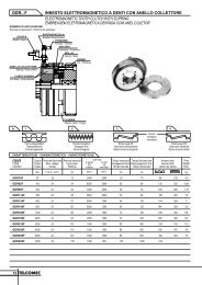
EMBRAGUES Y FRENOS MECÁNICOS Y ELECTROMAGNÉTICOSSerie 4.40ELECTROMAGNETIC SLIPRING TOOTHED CLUTCHESEMBRAGUES ELECTROMAGNETICOS DE DIENTES CON COLECTORSerie 4.40Size 04 08 11 23 45 10 18 36 55Torque Nm 40 100 160 300 500 1.000 2.000 4.000 6.000Voltage V 24*21Power W 12 20 29 40 50 63 72 105 115Weight Kg 0,5 1 1,50 2,3 3,4 6,2 10,5 20 24Speed max. min -1 4.500 4.000 3.600 3.000 2.500 2.100 1.800 1.400 1.000Magnet side 4 8 15 35 75 220 450 1.500 1.800J Kg cm 2Armat. Side 1,5 3 7 22 45 150 220 1.000 1.500Ø A min. 15 17 20 21 21 31 41 48 51Ø A max. 25 30 40 48 55 75 85 100 110Ø C H 7 32 42 50 60 70 90 100 130 150Ø D 70 82 95 114 134 168 198 250 262Ø E 28 36,5 44 53 60 80 90 112 123K 6 8 8 8 10 10 10 10 10L 29 38 40 45 55 62 70 83 89M 17 23 25 27,5 31 35 38,5 42,5 46P 4,5 5 5,5 6 7 7 7 8,5 8,5S 0,3 0,3 0,4 0,4 0,4 0,5 0,6 0,8 0,8Ø U max. 34 44 54 65 76 101 119 151 162SCREWS 3xM4 3xM5 3xM6 3xM6 3xM8 6xM8 6xM10 6xM12 6xM14Disc fixing Ø B 45 55 65 80 100 120 150 180 190PINS 2Ø5 2Ø6 2Ø6 2Ø8 2Ø10 3Ø10 3Ø12 3Ø14 3Ø18N. Keyw 1 1 1 2 a 180 2 a 180 2 a 180 4 a 90 4 a 90 4 a 90THE TEETH CAN BE TRAPEZOIDAL OR TRIANGULAR FORM • EL DENTADO PUEDE SER TRAPECIAL O TRIANGULAR* OTHER VOLTAGE UNDER REQUEST • OTRAS TENSIONES BAJO DEMANDA
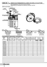
MECHANICAL AND ELECTROMAGNETIC CLUTCHES AND BRAKESSerie 4.41ELECTROMAGNETIC STATIONARY-FIELD TOOTHED CLUTCHESEMBRAGUES ELECTROMAGNETICOS A DIENTES DE BOBINA ESTATICASerie 4.41Size 04 07 16 23 45 90 18 3022Torque Nm 40 70 160 250 400 900 2.000 3.000Voltage V 24*Power W 20 24 32 45 58 80 100 114Weight Kg 1,3 1,7 2,7 3,5 6,7 11,5 14 18Speed max. min -1 4.000 4.000 3.500 3.000 2.500 2.000 2.000 2.000Magnet side 1,5 2 7 12 28 65 190 240J Kg cm 2Armat. side 1,5 3,5 9 17 40 100 250 490Ø A min. 15 17 15 20 25 35 41 40Ø A max. 20 25 30 42 46 60 65 65Ø C H7 32 40 50 60 65 90 100 105Ø D 73 82 98 115 134 168 198 210Ø E 28 38 43 53 58 80 90 105M 34 35 36 42 45 53 67 74S 0,3 0,3 0,4 0,4 0,4 0,6 0,6 0,6T 47 48 52 59 65 76 98 113a 1 2 2 2 2 2 2 2b 3 3 3 4 5 6 8 8c 6 6 6 8 8 8 12 12SCREWS 3xM4 3xM5 3xM6 3xM6 3xM8 6xM8 3xM10 6xM10Disc fixing Ø B 45 52 65 75 85 110 150 160PINS 2Ø5 2Ø6 2Ø6 2Ø8 3Ø10 3Ø10 3Ø12 3Ø12THE TEETH CAN BE TRAPEZOIDAL OR TRIANGULAR FORM • EL DENTADO PUEDE SER TRAPECIAL O TRIANGULAR* OTHER VOLTAGE UNDER REQUEST • OTRAS TENSIONES BAJO DEMANDA
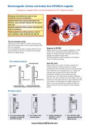
EMBRAGUES Y FRENOS MECÁNICOS Y ELECTROMAGNÉTICOSSerie 4.42ELECTROMAGNETIC STATIONARY FIELD TOOTHED CLUTCHESEMBRAGUES ELECTROMAGNETICOS DE DIENTES DE BOBINA ESTATICASerie 4.42Size 02 05 11 23 60 10 25Torque Nm 20 50 100 200 400 800 2.500Voltage V 24*23Power W 24 34 46 52 58 84 144Weight Kg 1,2 2,4 4,5 7,6 14,2 22,2 51,6Speed max. min -1 15.000 10.000 9.000 6.700 5.600 4.800 2.200Magnet side 2,06 7,35 17,9 49,9 136,6 273 1.143J Kg cm 2Armat. side 1,16 3,48 9,2 21,1 64,4 120 540Ø A min. 18 25 35 45 60 70 90Ø A max. 11 15 19 24 30 39 50Ø C H7 52 72 82 110 135 160 190Ø D 82 106 127 157 195 225 295M 44 50 58 66 80 95 125S 0,2 0,2 0,3 0,3 0,3 0,4 0,5T 5,4 6 8 9 11 13 18bxc 3x6 3x6 3x6 3x6 4x8 5x8 12x14SCREWS 4xM4 4xM4 4xM6 4xM6 4xM8 4xM10 4xM12Disc fixing Ø B 62 82 95 123 152 180 220PINS 2Ø4 2Ø5 2Ø6 2Ø8 2Ø10 2Ø12 2Ø14THE TEETH CAN BE TRAPEZOIDAL OR TRIANGULAR FORM • EL DENTADO PUEDE SER TRAPECIAL O TRIANGULAR* OTHER VOLTAGE UNDER REQUEST • OTRAS TENSIONES BAJO DEMANDA
MECHANICAL AND ELECTROMAGNETIC CLUTCHES AND BRAKESELECTROMAGNETIC CLUTCHES ANDBRAKES 4.50 AND 4.53 SERIESEMBRAGUES Y FRENOS ELECTRO-MAGNETICOS SERIES 4.50 Y 4.5324Due to the design the magnetic field establishedby the coil doesn't pass through the plates andthat is why the response times are very quick.Referring to the clutch, the magnetic body willbe mounted on the motor shaft, in continuosrotation so that the moment of inertia of themasses in motion during every operation is notincreased and besides we avoid to apply thecurrent to a stopped collector during every start,which may cause sparks specially working in oil.Their main characteristic is: multiple plates fordry or wet operation.Por su diseño, el campo magnético creado por labobina no atraviesa los discos y por ello los tiemposde respuesta son muy rápidos.Cuando se trata de un embrague, el cuerpomagnético se montará sobre el eje motor, es decir,en rotación contínua, a fin de no aumentar elmomento de inercia de las masas a poner enmovimiento en cada maniobra y además se evitatener que aplicar la corriente en cada arranquesobre un colector parado, que puede ocasionarchispas sobre él, especialmente cuando funcionaen aceite.Su característica principal es que lleva discossinterizados que pueden funcionarindistintamente en seco en baño de aceite.
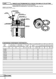
EMBRAGUES Y FRENOS MECÁNICOS Y ELECTROMAGNÉTICOSSerie 4.50ELECTROMAGNETIC SLIPRING MULTI-PLATE CLUTCHESEMBRAGUES ELECTROMAGNETICOS MULTIDISCO CON COLECTORSerie 4.50Size 02 05 11 23 45Torque Nm 20 50 110 230 45025Voltage V 24*Power W 20 26 34 48 60Weight Kg 1,6 2,7 4,8 7,5 10,5Speed max. min -1 3.200 3.000 2.800 2.500 2.000Int. 17 40 95 225 450J Kg cm 2Ext 10 20 50 100 225Ø A min. 15 15 16 25 30Ø A max. 20 28 35 45 55Ø B 95 114 134 168 198Ø C min. 38 48 58 70 80Ø D 103 118 145 170 198K 8 8 10 10 10L 44 51 56 64 73,5N 5 6 8 8 10P 4,5 6 6,5 7 7S max. engaged 0,30 0,35 0,40 0,40 0,50* OTHER VOLTAGE UNDER REQUEST • OTRAS TENSIONES BAJO DEMANDA
MECHANICAL AND ELECTROMAGNETIC CLUTCHES AND BRAKESSerie 4.53ELECTROMAGNETIC MULTI-PLATE BRAKESFRENOS ELECTROMAGNETICOS MULTIDISCOSerie 4.53Size 02 05 11 23 4526Torque Nm 20 50 110 230 450Voltage V 24*Power W 20 26 34 48 60Weight Kg 1,6 2,7 4,8 7,5 10,5Speed max. min -1 6.000 4.800 4.000 3.200 2.800int. 17 40 95 225 450J Kg cm 2Ext. 10 20 50 100 225Ø A 20 28 38 45 55Ø B 83 102 120 140 170Ø C min. 38 48 58 70 80Ø D 103 118 145 170 198Ø E 72 92 110 130 156Ø FH 7 38 50 60 70 85L 44 51 56 64 73,5N 5 6 8 8 10S max. engaged 0,30 0,35 0,40 0,40 0,50T 8 8 10 12 15Ø R M4 M5 M6 M8 M10* OTHER VOLTAGE UNDER REQUEST • OTRAS TENSIONES BAJO DEMANDA
EMBRAGUES Y FRENOS MECÁNICOS Y ELECTROMAGNÉTICOSASSEMBLY EXAMPLES • EJEMPLOS DE MONTAJESERIE 4.40 SERIE 4.4127SERIE 4.42SERIE 4.50 SERIE 4.53
MECHANICAL AND ELECTROMAGNETIC CLUTCHES AND BRAKESELECTROMAGNETIC SINGLE-DISCCLUTCHES AND BRAKESThese clutches and brakes dispose of multipleapplications due to their characteristicconstruction: Wrapping machines, printingmachines, computers.They are self-regulating within extensive limitsand their torque after the first adapting wearwill not suffer variation.At the releasing position they haven't residualtorque thanks to a spring incorporated into thearmature. Their operation is effectuated in dryrunning und the friction disc have to be protectedagainst all oil or grease projections.Since the friction during the clutching and brakingmoment takes place also between metallic parts,it is normal that same parts are presenting groovesund lines through the ages.EMBRAGUES Y FRENOSELECTROMAGNÉTICOS MONODISCOPor su construcción peculiar, estos embraques yfrenos tienen múltiples aplicaciones: Envolvedoras,máquinas de imprimir, ordenadores, etc.. Sonautoregulantes dentro de unos amplios límites ysu par, una vez sufrido el primer desgaste deadaptación no sufre variación.En posición de desembragado, no tienen parresidual gracias a un resorte que Ileva incorporadola armadura. Su funcionamiento es en seco y hayque proteger los discos de fricción contra todaproyección de aceite o grasa.Como el roce en el momento de embragar ofrenar tiene lugar también entre partes metálicas,es normal que a través del tiempo surjan en lasmismas surcos y rayas.28
EMBRAGUES Y FRENOS MECÁNICOS Y ELECTROMAGNÉTICOSSerie 4.60 - 4.61SERIE 4.60 SERIE 4.61ELECTROMAGNETIC STATIONARY-FIELD SINGLE DISC CLUTCHESEMBRAGUES ELECTROMAGNETICOS MONODISCO DE BOBINA ESTATICASerie 4.60 - 4.61Size 94 95 01 02 04 08 16 32Torque Nm 2 7,5 15 30 60 120 240 480Voltage V 24*Power W 10 13 27 27 36 51 72 824.60 0,20 0,50 0,85 1,5 2,8 5 9,5 17,5WeightKg4.61 0,30 0,60 1,20 2 3,6 6 11 19,5Speed max. min -1 8.000 7.000 6.000 5.000 4.000 3.000 3.000 2.000Rotor 0,20 0,75 2 7 23 65 197 475J Arm. - 4.60 Kg cm 2 0,08 0,5 1,4 5 18 55 150 380Arm. - 4.61 0,15 0,8 2,4 9 28 80 280 700Ø A H7 min. 9 10 15 15 15 21 21 25Ø A H7 max. 10 15 25 30 40 50 70 80B - 3,5 4,25 5 5,5 6 7 8Ø C H8 18 35 42 52 62 80 100 125D 2,5 2 2,5 3 3,5 3,5 4 4Ø E 52 72 90 112 138 175 215 270ØF h9 62 83 100 125 150 190 230 290G 20 22 24 27 30 34 40 47H 22,5 24 26,5 30 33,5 37,5 44 51I 3,8 3,8 4,5 5,9 6,8 8,5 10,5 12Ø K 7 7 7 9,5 11 14 17 20Ø M 2x4,1 3x4,1 3x4,1 3x5,2 3x6,2 3x8,2 3x 10,2 4x12,2Ø N 8 8,5 8,5 10,5 12 15,5 18 22Ø P 29 46 60 76 95 120 158 210Q 2 2 2,5 3 3,5 4 5 6Ø R 3x4,3 4x4,5 4x5,5 4x6,5 4x6,5 4x8,5 4x8,5 4x10,5S 0,2 0,2 0,2 0,2 0,3 0,3 0,5 0,5Ø T 42 63 80 100 125 160 200 250Ø U 45 67 85 107 135 171 215 266Z 1,8 1,8 1,8 2 2 3 4 5a 26,5 28 31,2 36,1 40,6 46,3 55 63,5b 12 15 20 25 30 38 48 55Ø d M4 M4 M5 M5 M6 M8 M8 M10Ø e min. 8 10 10 11 14 19 25 21Ø e max. 10 15 20 30 35 50 65 80h 3 5 6 6 10 10 15 20i 38,5 43 51,2 61,1 70,6 84,3 103 118,5Ø m 17 27 38 42 52 65 83 10529FOR DRY OPERATION • FUNCIONAMIENTO EN SECO / * OTHER VOLTAGE UNDER REQUEST • OTRAS TENSIONES BAJO DEMANDA
MECHANICAL AND ELECTROMAGNETIC CLUTCHES AND BRAKESSerie 4.61 A - 4.61 BSERIE 4.61 ASERIE 4.61 BELECTROMAGNETIC STATIONARY-FIELD SINGLE DISC CLUTCHESEMBRAGUES ELECTROMAGNETICOS MONODISCO DE BOBINA ESTATICA30Serie4.61 A - 4.61 BSize 94 95 01 02 04 08 16 32Torque Nm 2 7,5 15 30 60 120 240 480Voltage V 24*Power W 8 10 15 21 24 38 52 60461 - 1 1,5 3 5 8 15 25WeightKg4.61 B - 1 1,6 2,8 5 9 17 30Speed max min -1 8.000 7.000 6.000 5.000 4.000 3.000 3.000 2.000Rotor- 0,20 0,75 2 7 23 65 197 475J Arm.-4.61 A Kg cm 2 - 1 3 9,5 26,5 89 270 750Arm.-4.61 B - 4,3 12 47 128 450 1.280 3.330Ø A H7 min. 9 10 15 15 15 21 21 25Ø A H7 max. 10 15 25 30 40 50 70 80B - 3,5 4,25 5 5,5 6 7 8Ø C H8 18 35 42 52 62 80 100 125D 2,5 2 2,5 3 3,5 3,5 4 4Ø E 52 72 90 112 138 175 215 270Ø F h9 62 83 100 125 150 190 230 290G 20 22 24 27 30 34 40 47H 22,5 24 26,5 30 33,5 37,5 44 51J - 31,5 35,2 41,1 46,6 53,3 64 74,5L - 51 61,2 71 86 104,3 123,5 146N 49,5 54 60 69 77,5 88 105 122O - 17 22 26,5 35,5 44,5 52,5 64Q 2 2 2,5 3 3,5 4 5 6Ø R 3x4,3 4x4,5 4x5,5 4x6,5 4x6,5 4x8.5 4x8,5 4x10,5S 0,2 0,2 0,2 0,2 0,3 0,3 0,5 0,5V 17 18 20 22 24 26 30 35Ø X - 12 15 20 25 30 40 45Ø Y k6 - 38 45 55 65 75 90 115b 12 15 20 25 30 38 48 55c - 5 6,5 7,5 8,5 9 12 14Ø e min. 8 10 10 11 14 19 25 21Ø e max. 10 15 20 30 35 50 65 80f - 2,5 3 2,5 4 4 4 5g - 22 28,2 33,5 44 57,8 67,5 81h x j x l - 6x6x14 8x7x18 8x7x25 10x8x32 12x8x36 14x9x45 16x10x56q 12 10,5 8,7 8,1 7,1 3,6 2 3,5FOR DRY OPERATION • FUNCIONAMIENTO EN SECO / * OTHER VOLTAGE UNDER REQUEST • OTRAS TENSIONES BAJO DEMANDA
EMBRAGUES Y FRENOS MECÁNICOS Y ELECTROMAGNÉTICOSSerie 4.62 - 4.63 - 4.64SERIE 4.62 SERIE 4.62 SERIE 4.62ELECTROMAGNETIC SINGLE DISC BRAKES • FRENOS ELECTROMAGNETICOS MONODISCOSerie 4.62 - 4.63 - 4.64Size 94 95 01 02 04 08 16 32Torque Nm 2 7,5 15 30 60 120 240 480Voltage V 24*Power W 8 10 22 27 36 38 52 604.62 0,16 0,30 0,5 1 1,70 3,80 6 11Weightkg4.63 - 4.64 0,18 0,40 0,70 1,30 2,20 4 7,5 12,5Speed max. min -1 8.000 7.000 6.000 5.000 4.000 3.000 2.500 2.000Arm. – 4.62 0,08 0,5 1,4 5 18 55 150 380J Kg cm 2Arm. - 4.63 - 4.64 0,15 0,8 2,4 9 28 80 280 700B - 3,5 4,25 5 5,5 6 7 8B 1 - 1,6 1,85 2,15 2,15 2,65 3,15 4,15Ø C H8 18 35 42 52 62 80 100 125Ø C 2 - 37 44,5 55 65 82,1 103,5 129Ø E 52 72 90 112 138 175 215 270Ø F h9 62 83 100 125 150 190 230 290I 3,8 3,8 4,5 5,9 6,8 8,3 10,5 12Ø K 7 7 7 10 10 14 17 20L 1 21 22 24,7 28,1 31,1 34,6 41 47,5Ø M 2x4,1 3x4,1 3x4,1 3x5,2 3x6,2 3x8,2 3x10,2 4x12,2Ø N 8 8,5 8,5 10,5 12 15,5 18,5 22Ø P 29 46 60 76 95 120 158 210Q 2 2 2,5 3 3,5 4 5 6Ø R 3x4,3 4x4,5 4x5,5 4x6,5 4x6,5 4x8,5 4x8,5 4x10,5S 0,2 0,2 0,2 0,2 0,3 0,3 0,5 0,5Ø T 42 63 80 100 125 160 200 250V 17 18 20 22 24 26 30 35Z 1,8 1,8 1,8 2 2 3 4 5b 12 15 20 25 30 38 48 55Ø d M4 M4 M5 M5 M6 M8 M8 M10Ø e min. 8 10 10 11 14 19 25 21Ø e max. 10 15 20 30 35 50 65 80h 5 5 6 6 10 10 15 20I 1 33 37 44,7 53,1 61,1 72,6 89 102,5Ø m 18,5 27 38 42 52 65 83 105n 24 25,5 28,7 33,1 37,1 41,6 50 58,531FOR DRY OPERATION • FUNCIONAMIENTO EN SECO/ * OTHER VOLTAGE UNDER REQUEST • OTRAS TENSIONES BAJO DEMANDA
MECHANICAL AND ELECTROMAGNETIC CLUTCHES AND BRAKESSerie 4.67 - 4.68 - 4.68 ASERIE 4.67 SERIE 4.68 SERIE 4.68 AELECTROMAGNETIC STATIONARY-FIELD SINGLE DISC CLUTCHESEMBRAGUES ELECTROMAGNETICOS MONODISCO DE BOBINA ESTATICA32Serie4.67 - 4.68 - 4.68 ASize 95 01 02 04 08 16 32Torque Nm 7,5 15 30 60 120 240 480Voltage V 24*Power W 13 22 27 36 51 72 824.67 1 1,4 2,5 4,2 7,5 14 22Weight 4.68 Kg 1,1 1,6 3 4,8 8,3 15 234.68 A 1,5 2,2 4 6,5 10,5 19,5 29,5Speed max. min -1 8.000 6.000 5.000 4.000 3.000 3.000 2.000Rotor 1,5 3,1 8,9 25,1 74 225 580J Arm. - 4.67 Kg cm2 Arm. - 4.680,50,81,42,45918285580150280380700Arm. - 4.68 A 1 3 10 32 92 340 950Ø A H7 min. 10 13 15 15 21 30 35Ø A H7 max. 20 22 30 40 50 60 70Ø C H8 35 42 52 62 80 100 125D 6,5 8,7 11,1 13,1 15,6 20 23,5E 40,5 43,5 49 55,5 61,5 74 81G 47 52 58,1 68,6 77,1 94 104,5H 26,5 28,5 35 36 39 48 57I 14 15 14 19,5 20 25,5 26J 3,8 4,5 5,9 6,8 8,3 10,5 12K 1,8 1,8 2 2 3 4 5L 67,5 78,2 90 108 128,1 153,5 176Ø M 3x4,1 3x4,1 3x5,2 3x6,2 3x8,2 3x10,2 4x12,2O 17 22 26,5 35,5 44,5 52,5 63Ø P 46 60 76 95 120 158 210Q 37,5 46 55,5 71 93,5 113,1 139R 4,1 4,1 4,1 4,1 8,1 10,1 8,1S 0,2 0,2 0,2 0,3 0,3 0,5 0,5Ø T 63 80 100 125 160 200 250Ø U 67 85 107 135 171 215 266V 4 4 4 4 6 6 6Ø X 12 15 20 25 30 40 45Ø Y k6 38 45 55 65 75 90 115b 15 20 25 30 38 48 55c 5 6,5 7,5 8,5 9 12 14Ø d M4 M5 M5 M6 M8 M8 M10Ø e min. 10 10 11 14 19 25 21Ø e max. 15 20 30 35 50 65 80f 2,5 3 2,5 4 4 4 5g 22 28,2 33,5 44 57,8 67,5 81h 5 6 10 10 10 15 20Ø m 27 38 42 52 65 83 105FOR DRY OPERATION • FUNCIONAMIENTO EN SECO/ * OTHER VOLTAGE UNDER REQUEST • OTRAS TENSIONES BAJO DEMANDA
EMBRAGUES Y FRENOS MECÁNICOS Y ELECTROMAGNÉTICOSSerie 4.74 - 4.76SERIE 4.76 SERIE 4.74SPRING APPLIED ELECTROMAGNETIC SAFETY BRAKESFRENOS ELECTROMAGNETICOS DE SEGURIDAD ACCIONADOS POR RESORTESSerie 4.76 4.74Size 95 01 02 04 05 11 23 45Torque Nm 4 8 16 32 60 120 240 400Voltage V 24-96-190Power W 18 24 30 37 52 72 82 101Weight Kg 1,6 2,8 4,5 6 8 13 20 38J Kg cm 2 0,18 0,5 1,8 3,6 13 30 50 170Ø A min. 11 15 15,20 20,25 18 20 28 35Ø A max. 15 20 24 30 35 40 48 65Ø A 1 58 68 78 101B 18 20 20 25 30 35 40 50Ø C 84 103 127 147 162 192 220 295Ø D 72 90 112 132 145 170 195 270Ø D 2 20 30 40 45 55 71 75 90Ø D 3 90 110 135 158 170 200 230 306Ø D 4 30 38 52 60 75 75 85 120Ø E 32 40 54 63 80 80 90 125Ø F 6 8 8 10 10 12 14 16G 1,25 2,25 2,25 2,75 3 3,5 4 4,5Ø H 62 80 99 119 124 146 171 240I 6,5 8 9 9 11 12 12 13Ø K 25 31 37 44 50 55 65 75L 36,5 43 52,5 57 62,5 71,5 83,5 98,5L 1 43 51 61,5 66 73,5 83,5 95,5 111,5L 2 max. 50,5 56 65 72 82 93 110 129M 50 50 55 55 72 94 112 140N 19,5 25 27,5 32 18 20 22 26P 52,5 66 76 86 102 116 135 180Q 92 110 132 165Q 1 32 40 48 58Ø R 3 M4 3 M5 3 M6 3 M6 3 M8 3 M8 6 M10 6 M10Ø R 1 3x4,5 3x5,5 3x6,5 3x6,5 3x9 3x9 6x11 6x11R 2 1,5 2 2,5 2,5 3 3 4 5S + 0,10 0,20 0,20 0,20 0,30 0,30 0,40 0,50V 4 5 6 7 8 9 10 11Z 72 90 112 132 165 194 222 29833
MECHANICAL AND ELECTROMAGNETIC CLUTCHES AND BRAKESACCESORIES • ACCESORIOS10 34ACCESORIESThe simplest models of the 4.74 and 4.76 seriescan be completed with several available accesoriesto get a wide range of custom-buit models.1. - PROTECTION RING2. - FRICTION PLATE3. - ADJUSTING SCREW4. - MANUAL RELEASE5. - FRICTION DISCACCESORIOSLas versiones más simples de las series 4.74 y 4.76pueden completarse con diversos accesoriosdisponibles consiguiéndose una amplia gama deversiones según las necesidades del cliente.1. - ANILLO DE PROTECCION2. - PLATO DE FRICCION3. - TUERCA DE REGULACION4. - DESBLOQUEO MANUAL5. - DISCO DE FRICCIÓN
EMBRAGUES Y FRENOS MECÁNICOS Y ELECTROMAGNÉTICOSASSAMBLY EXAMPLES • EJEMPLOS DE MONTAJESERIE 4.60SERIE 4.6211 35SERIE 4.64 SERIE 4.67SERIE 4.75 SERIE 4.71
MECHANICAL AND ELECTROMAGNETIC CLUTCHES AND BRAKESELECTRICAL ACCESORIES • ACCESORIOS ELÉCTRICOS10 36RECTIFIERSThe rectifying units are provided with a connectingblock with AC input terminals, DC output terminalsand additional terminals for shunting currentbreakdown from auxiliary contacts of the motorswitch and, as a result, getting a faster responsespeed.RECTIFICADORESEstos equipos rectificadores presentan una regletade conexiones con las bornas de entrada decorriente alterna, las de salida en continua yademás dos bornas complementarias para derivarla ruptura de corriente desde contactos auxiliaresdel interruptor del motor, para conseguir de estaforma una mayor velocidad de respuesta.CONNECTION EXAMPLES • EJEMPOS DE CONEXIONES
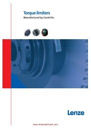
EMBRAGUES Y FRENOS MECÁNICOS Y ELECTROMAGNÉTICOSELECTRICAL ACCESORIES • ACCESORIOS ELÉCTRICOSSERIE 2.40.99.0812.40.99.08011 37SERIE 2.40.99.141POWER SUPPLYSerie 2.40.99.080. Carbon brush for dry operationSerie 2.40.99.081. Standard for wet operationSerie 2.40.99.141. Telescopic for wet operationTOMAS DE CORRIENTESerie 2.40.99.080. Grafito para funcionamientoen secoSerie 2.40.99.081. Normal para funcionamientoen medio lubrificadoSerie 2.40.99.141. Telescópica para funcionamientoen medio lubrificado