read and save these instructions lea y conserve estas ... - Datatail
read and save these instructions lea y conserve estas ... - Datatail
read and save these instructions lea y conserve estas ... - Datatail

Create successful ePaper yourself
Turn your PDF publications into a flip-book with our unique Google optimized e-Paper software.
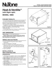
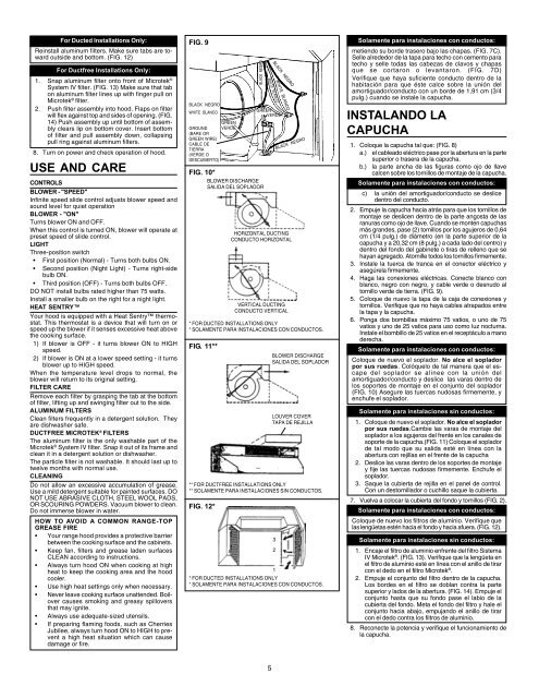
For Ducted Installations Only:Reinstall aluminum filters. Make sure tabs are towardoutside <strong>and</strong> bottom. (FIG. 12)For Ductfree Installations Only:1. Snap aluminum filter onto front of Microtek ®System IV filter. (FIG. 13) Make sure that tabon aluminum filter lines up with finger pull onMicrotek ® filter.2. Push filter assembly into hood. Flaps on filterwill flex against top <strong>and</strong> sides of opening. (FIG.14) Push assembly up until bottom of assemblyc<strong>lea</strong>rs lip on bottom cover. Insert bottomof filter <strong>and</strong> pull assembly down, collapsingpull ring against aluminum filters.8. Turn on power <strong>and</strong> check operation of hood.USE AND CARECONTROLSBLOWER - "SPEED"Infinite speed slide control adjusts blower speed <strong>and</strong>sound level for quiet operationBLOWER - "ON"Turns blower ON <strong>and</strong> OFF.When this control is turned ON, blower will operate atpreset speed of slide control.LIGHTThree-position switch• First position (Normal) - Turns both bulbs ON.• Second position (Night Light) - Turns right-sidebulb ON.• Third position (OFF) - Turns both bulbs OFF.DO NOT install bulbs rated higher than 75 watts.Install a smaller bulb on the right for a night light.HEAT SENTRYYour hood is equipped with a Heat Sentry thermostat.This thermostat is a device that will turn on orspeed up the blower if it senses excessive heat abovethe cooking surface.1) If blower is OFF - it turns blower ON to HIGHspeed.2) If blower is ON at a lower speed setting - it turnsblower up to HIGH speed.When the temperature level drops to normal, theblower will return to its original setting.FILTER CARERemove each filter by grasping the tab at the bottomof filter, lifting up <strong>and</strong> swinging filter out to the side.ALUMINUM FILTERSC<strong>lea</strong>n filters frequently in a detergent solution. Theyare dishwasher safe.DUCTFREE MICROTEK ® FILTERSThe aluminum filter is the only washable part of theMicrotek ® System IV filter. Snap it out of its frame <strong>and</strong>c<strong>lea</strong>n it in a detergent solution or dishwasher.The particle filter is not washable. It should last up totwelve months with normal use.CLEANINGDo not allow an excessive accumulation of grease.Use a mild detergent suitable for painted surfaces. DONOT USE ABRASIVE CLOTH, STEEL WOOL PADS,OR SCOURING POWDERS. Vacuum blower to c<strong>lea</strong>n.Do not immerse blower in water.HOW TO AVOID A COMMON RANGE-TOPGREASE FIRE• Your range hood provides a protective barrierbetween the cooking surface <strong>and</strong> the cabinets.• Keep fan, filters <strong>and</strong> grease laden surfacesCLEAN according to <strong>instructions</strong>.• Always turn hood ON when cooking at highheat to keep the cooking area <strong>and</strong> the hoodcooler.• Use high heat settings only when necessary.• Never <strong>lea</strong>ve cooking surface unattended. Boilovercauses smoking <strong>and</strong> greasy spilloversthat may ignite.• Always use adequate-sized utensils.• If preparing flaming foods, such as CherriesJubilee, always turn hood ON to HIGH to preventa high heat situation which can causedamage or fire.FIG. 9BLACK NEGROWHITE BLANCOGREENGROUND VERDE(BARE ORGREEN WIRE)CABLE DETIERRA(VERDE ODESCUBIERTO)BLACK NEGROFIG. 10*BLOWER DISCHARGESALIDA DEL SOPLADORFIG. 11**FIG. 12*WHITE BLANCOBLACK NEGROWHITE BLANCOGREENVERDEHORIZONTAL DUCTINGCONDUCTO HORIZONTALVERTICAL DUCTINGCONDUCTO VERTICALBLOWER DISCHARGESALIDA DEL SOPLADOR1* FOR DUCTED INSTALLATIONS ONLY* SOLAMENTE PARA INSTALACIONES CON CONDUCTOS.32BLACK NEGRO* FOR DUCTED INSTALLATIONS ONLY* SOLAMENTE PARA INSTALACIONES CON CONDUCTOS.LOUVER COVERTAPA DE REJILLA** FOR DUCTFREE INSTALLATIONS ONLY** SOLAMENTE PARA INSTALACIONES SIN CONDUCTOS.Solamente para instalaciones con conductos:metiendo su borde trasero bajo las chapas. (FIG. 7C).Selle alrededor de la tapa para techo con cemento paratecho y selle todas las cabezas de clavos y chapasque se cortaron o levantaron. (FIG. 7D)Verifique que haya suficiente conducto dentro de lahabitación para que éste calce sobre la unión delamortiguador/conducto con un borde de 1,91 cm (3/4pulg.) cu<strong>and</strong>o se instale la capucha.INSTALANDO LACAPUCHA1. Coloque la capucha tal que: (FIG. 8)a.) el cab<strong>lea</strong>do eléctrico pase por la abertura en la partesuperior o trasera de la capucha.b.) la parte ancha de las figuras como ojo de llavecalcen sobre los tornillos de montaje de la capucha.Solamente para instalaciones con conductos:c) la unión del amortiguador/conducto se deslicedentro del conducto.2. Empuje la capucha hacia atrás para que los tornillos demontaje se deslicen dentro de la parte angosta de lasranuras como ojo de llave. Cu<strong>and</strong>o se monten capuchasmás gr<strong>and</strong>es, pase (2) tornillos por los agujeros de 0,64cm (1/4 pulg.) de diámetro (en la parte superior de lacapucha y a 20,32 cm (8 pulg.) a cada lado del centro) ydentro del fondo del gabinete o tiras de relleno que sehayan agregado. Atornille todos los tornillos firmemente.3. Instale la tuerca de tranca en el conector eléctrico yasegúrela firmemente.4. Haga las conexiones eléctricas. Conecte blanco conblanco, negro con negro, y cable verde o desnudo altornillo verde de tierra. (FIG. 9).5. Coloque de nuevo la tapa de la caja de conexiones ytornillos. Verifique que no haya cables atrapados entrela tapa y la capucha.6. Ponga dos bombillas máximo 75 vatios, o uno de 75vatios y uno de 25 vatios para uso como luz nocturna.Instale el bombillo de 25 vatios en el receptáculo a manoderecha.Solamente para instalaciones con conductos:Coloque de nuevo el soplador. No alce el sopladorpor sus ruedas. Colóquelo de tal manera que el escapedel soplador se alinee con la unión delamortiguador/conducto y deslice las varas dentro delos soportes de montaje en el conjunto del soplador(FIG. 10) Asegure las tuercas nudosas firmemente, yenchufe el soplador.Solamente para instalaciones sin conductos:1. Coloque de nuevo el soplador. No alce el sopladorpor sus ruedas.Cambie las varas de montaje delsoplador a los agujeros del frente en los canales desoporte de la capucha.(FIG. 11) Coloque el sopladorde tal modo que su salida esté en línea con laabertura con rejillas en el frente de la capucha2. Deslice las varas dentro de los soportes de montajey fije las tuercas nudosas firmemente. Enchufe elsoplador.3. Saque la cubierta de rejilla en el panel de control.Con un destornillador o cuchillo saque la cubierta.7. Vuelva a colocar la cubierta del fondo y tornillos (FIG. 2).Solamente para instalaciones con conductos:Coloque de nuevo los filtros de aluminio. Verifique quelas lengüetas estén hacia el fondo y hacia afuera. (FIG. 12).Solamente para instalaciones sin conductos:1. Encaje el filtro de aluminio enfrente del filtro SistemaIV Microtek ® . (FIG. 13). Verifique que la lengüeta enel filtro de aluminio esté en línea con el anillo de tirarcon el dedo en el filtro Microtek ® .2. Empuje el conjunto del filtro dentro de la capucha.Los bordes en el filtro se doblan contra la partesuperior y lados de la abertura. (FIG. 14). Empuje elconjunto hasta que su fondo pase el labio de lacubierta del fondo. Meta el fondo del filtro y hale elconjunto hacia abajo, empuj<strong>and</strong>o el anillo de tirarcon el dedo contra los filtros de aluminio.8. Reconecte la potencia y verifique el funcionamiento dela capucha.5