read and save these instructions lea y conserve estas ... - Datatail
read and save these instructions lea y conserve estas ... - Datatail
read and save these instructions lea y conserve estas ... - Datatail

You also want an ePaper? Increase the reach of your titles
YUMPU automatically turns print PDFs into web optimized ePapers that Google loves.
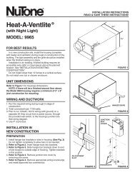
88000 SERIES/MICROTEK ® SYSTEM IVCONVERTIBLE RANGE HOODINSTALLATION INSTRUCTIONSREAD AND SAVETHESE INSTRUCTIONSFor Ductfree Installation:Follow all general steps <strong>and</strong>:purchase a 97007662 Microtek ® System IV FilterKit, available from your Broan Distributor or writeBroan Mfg. Co., Inc., P.O. Box 140, Hartford WI,53027, USA.! INTENDED FOR DOMESTICCOOKING ONLY. !WARNINGTO REDUCE THE RISK OF FIRE, ELECTRIC SHOCK, ORINJURY TO PERSONS, OBSERVE THE FOLLOWING:1. Use this unit only in the manner intended by themanufacturer. If you have questions, contact themanufacturer at the address or telephone numberlisted in the warranty.2. Before servicing or c<strong>lea</strong>ning unit, switch power offat service panel <strong>and</strong> lock the service disconnectingmeans to prevent power from being switched onaccidentally. When the service disconnecting meanscannot be locked, securely fasten a prominent warningdevice, such as a tag, to the service panel.3. Installation work <strong>and</strong> electrical wiring must be doneby a qualified person(s) in accordance with all applicablecodes <strong>and</strong> st<strong>and</strong>ards, including fire-rated constructioncodes <strong>and</strong> st<strong>and</strong>ards.4. Sufficient air is needed for proper combustion <strong>and</strong>exhausting of gases through the flue (chimney) offuel burning equipment to prevent backdrafting. Followthe heating equipment manufacturer’s guideline<strong>and</strong> safety st<strong>and</strong>ards such as those published bythe National Fire Protection Association (NFPA), <strong>and</strong>the American Society for Heating, Refrigeration <strong>and</strong>Air Conditioning Engineers (ASHRAE), <strong>and</strong> the localcode authorities.5. When cutting or drilling into wall or ceiling, do notdamage electrical wiring <strong>and</strong> other hidden utilities.6. To reduce the risk of fire or electric shock, do notuse this range hood with an additional speed controldevice.7. Ducted fans must always be vented to the outdoors.8. To reduce the risk of fire, use only metal ductwork.9. Use with approved cord-connection kit only.10. This unit must be grounded.TO REDUCE THE RISK OF A RANGE TOP GREASEFIRE:1. Never <strong>lea</strong>ve surface units unattended at high settings.Boilovers cause smoking <strong>and</strong> greasy spilloversthat may ignite. Heat oils slowly on low or mediumsettings.2. Always turn hood ON when cooking at high heat orwhen cooking flaming foods.3. C<strong>lea</strong>n ventilating fans frequently. Grease should notbe allowed to accumulate on fan or filter.4. Use proper pan size. Always use cookware appropriatefor the size of the surface element.TO REDUCE THE RISK OF INJURY TO PERSONS INTHE EVENT OF A RANGE TOP GREASE FIRE, OBSERVETHE FOLLOWING:*1. SMOTHER FLAMES with a close-fitting lid, cookiesheet, or metal tray, then turn off the burner. BECAREFUL TO PREVENT BURNS. If the flames donot go out immediately, EVACUATE AND CALL THEFIRE DEPARTMENT.2. NEVER PICK UP A FLAMING PAN — You may beburned.3. DO NOT USE WATER, including wet dishcloths ortowels - violent steam explosion will result.4. Use an extinguisher ONLY if:A. You know you have a Class ABC extinguisher<strong>and</strong> you al<strong>read</strong>y know how to operate it.B. The fire is small <strong>and</strong> contained in the area whereit started.C. The fire department is being called.D. You can fight the fire with your back to an exit.* Based on “Kitchen Fire Safety Tips” published byNFPA.SERIE 88000/MICROTEK ® SISTEMA IVINSTRUCCIONES PARA INSTALACIONDE CAPUCHA PARA ESTUFAELECTRICA CONVERTIBLELEA Y CONSERVEESTAS INSTRUCCIONESPara instalación sin conductos:Siga todos los pasos generales y:compre un juego de filtro 97007662 Microtek ® SistemaIV, disponible por parte de su distribuidor Broan oescriba a Broan Mfg. Co., Inc., P.O. Box 140, HartfordWI 53207, USA.! PREVISTO PARA COCINARDOMÉSTICO SOLAMENTE. !ADVERTENCIAPARA REDUCIR EL RIESGO DE INCENDIO, DESCARGAELECTRICA, O LESIONES PERSONALES, CUMPLA CON LOSSIGUIENTES PUNTOS:1. Solamente use esta unidad de la manera propuesta por elfabricante. Si tiene alguna pregunta, póngase en contactocon el fabricante en la dirección o teléfono anotados en lagarantía.2. Antes de limpiar o de poner en servicio la unidad, apague elinterruptor en el panel de servicio, y asegure el panel deservicio para evitar que se encienda accidentalmente.Cu<strong>and</strong>o el dispositivo para desconectar el servicio eléctricono puede ser cerrado con algún tipo de traba, sujetefuertemente al panel de servicio, una etiqueta de advertenciaprominente.3. El trabajo de instalación y el cab<strong>lea</strong>do eléctrico debenllevarse a cabo por personal calificado de acuerdo contodos los códigos y las normas aplicables, incluyendo loscódigos y normas de construcción contra incendios.4. Se requiere una cantidad de aire suficiente para lacombustión y escape de gases por la chimenea del equipoque quema combustible para evitar la retrogresión de lallama. Siga las especificaciones y estándares de seguridaddel fabricante, tales como los que publica la AsociaciónNacional de Protección Contra Incendios (NFPA por sussigles en inglés), y la Sociedad Americana de Ingenieros deCalefacción , Refrigeración y Aire Acondicionado (ASHRAE),y los códigos de las autoridades locales.5. Cu<strong>and</strong>o corte o taladre en una pared o cielo raso, no dañecab<strong>lea</strong>do eléctrico u otras instalaciones no visibles.6. Para reducir el riesgo de incendio o de descarga eléctrica,no utilice este ventilador con ningún dispositivo de unacontrol de velocidad de estado sólido adicional.7. Los abanicos con ducto deberán siempre tener una salidahacia el exterior.8. Para reducir el riesgo de incendio, use sólo ductos demetal.9. Uso con el kit aprobado del la conexión de la cuerdasolamente.10. Esta unidad se debe instalar con tierra efectiva.PARA REDUCIR EL RIESGO DE INCENDIO DEBIDO A GRASAACUMULADA EN LAS HORNILLAS:1. Nunca deje sin atender las unidades de superficie cu<strong>and</strong>otengan ajustes altos. Los reboses pueden provocar humo yderrames grasosos que se pueden incendiar. Calientelentamente el aceite en un ajuste bajo o medio.2. Siempre ENCIENDA la campana cu<strong>and</strong>o cocine con altatemperatura o cu<strong>and</strong>o cocine alimentos que se puedanincendiar.3. Limpie con frecuencia los ventiladores. No debe permitirque la grasa se acumule en el ventilador ni en el filtro.4. Utilice un sartén de tamaño adecuado. Siempre utilice elutensilio adecuado al tamaño del elemento de superficie.PARA REDUCIR EL RIESGO DE LESIONES PERSONALES ENCASO DE INCENDIO DE GRASA EN LA SUPERFICIE DE LAESTUFA, OBSERVAR LO SIGUIENTE:*1. Cubra y sofoque las llamas con una tapa ajustada, azafatede hornear galletas, o un azafate de metal, y luego apagueel calentador. TENGA CUIDADO PARA EVITARQUEMADURAS. Si las llamas no se apagan inmediatamente,HAY QUE EVACUAR Y LLAMAR LOS BOMBEROS.2. NUNCA ALCE UNA SARTEN QUE TENGA LLAMAS - Ustedse puede quemar.3. NO USE AGUA, incluyendo trapos lavaplatos mojados otoallas - puede que ocurran explosiones de vapor violentas.4. Use un extintor SOLAMENTE si:A. usted sabe que tiene un extintor ABC y ya sabe usarlo.B. el fuego es pequeño y está restringido al área dondeempezó.INSTALLER: Leave This Manual With The Homeowner. HOMEOWNER: Use <strong>and</strong> Care Information on Page 5.INSTALADOR: Deje este manual con el dueño de casa. DUEÑO DE CASA: Información del uso y mantenimiento en la página 6.
CAUTION !1. For general ventilating use only. Do not use toexhaust hazardous or explosive materials <strong>and</strong>vapors.2. To avoid motor bearing damage <strong>and</strong> noisy <strong>and</strong>/orunbalanced impellers, keep drywall spray,construction dust, etc. off power unit.3. This product is equipped with a thermostat whichmay start fan automatically. To reduce the risk ofinjury, switch power off at service panel <strong>and</strong> lockservice panel to prevent power from being switchedon automatically.4. Your hood motor has a thermal overload which willautomatically shut off the motor if it becomesoverheated. The motor will restart when it coolsdown. If the motor continues to shut off <strong>and</strong> restart,have the hood serviced.5. For best capture of cooking impurities, your rangehood should be mounted 18-24" above the cookingsurface.6. P<strong>lea</strong>se <strong>read</strong> specification label on product for furtherinformation <strong>and</strong> requirements.TOOLS ANDMATERIALS REQUIREDTOOLS Drill, electric or ratchet drive 1-1/4” Spade bit Common head <strong>and</strong> phillips head screwdriver Pliers Tape measure or ruler <strong>and</strong> pencilFor Ducted Installations Only: Saber Saw or drywall saw Metal snipsMATERIALS Electrical wiring <strong>and</strong> supplies of type to complywith local codesFor Ducted Installations Only: Roof or wall cap Roof cement or caulk Duct <strong>and</strong> duct tapeFor Ductfree Installations Only: One two-pack 97007662 Microtek ® System IVFilter KitFor Installation On Kitchen Cabinets With RecessedBottoms Only: Two 1” x 2” x 12” (approximate length) wood strips(purchase locally) Four 1-1/4” long flat head wood screws (purchaselocally) to fasten strips to cabinet bottomPLAN DUCTWORKINSTALLATIONFor Ducted Installations Only:Begin planning ductwork by deciding where ductwill run between hood <strong>and</strong> outside. For best performance,use shortest possible duct run <strong>and</strong> aminimum number of elbows. In more complex situations,3-1/4” x 10” duct can be converted to roundduct by means of a transition. FIGS 1A - 1E showseveral choices.FIG. 1A: Ducting directly through outside wall. Ifwall cap is used directly off back of hood, check tomake sure that damper flap in damper/duct connectoron hood does not interfere with damper flapin wall cap. If it does, remove flap on hood damper/duct connector.FIG. 1B: At times it will be easier to run duct vertically<strong>and</strong> use an elbow.FIG. 1C: Ducting straight up through roof using 3-1/4” x 10” duct. For single story installations.FIG. 1D: Straight up through roof using round duct.FIG. 1E: Ducting between ceiling joists for multistoryinstallations or through soffits above cabinetswhere soffit connects to outside walls.FIG. 1AFIG. 1BMODEL 429 ELBOWCODO MODELO 429MODEL 4013-1/4" X 10" DUCTMODELO 401CONDUCTO8,26 CM X25,40 CM(3-1/4 X 10 PULG.)FIG. 1CMODEL 634 OR 644ROOF CAPTAPA PARA TECHOMODELO 634 O 644MODEL 4013-1/4" X 10" DUCTMODELO 401CONDUCTO 8,26 CM X 25,40 CM(3-1/4 X 10 PULG.)FIG. 1DMODEL 634 OR 644 ROOF CAPTAPA PARA TECHO MODELO 634 O 644MODEL 406 6" ROUND DUCTMODELO 406 CONDUCTO REDONDODE 15,24 CM (6 PULG.)MODEL 411 3–1/4" X 10" TO 6"ROUND DUCT TRANSITIONMODELO 411TRANSICIÓN A CONDUCTO REDONDODE 8,26 CM X 25,40 CM A 15,24 CM(3-1/4 X 10 PULG. A 6 PULG.)FIG. 1EMODEL 419ADJUSTABLE ELBOWMODELO 419CODO AJUSTABLEMODEL 4113–1/4" X 10" TO 6"ROUND DUCT TRANSITIONMODELO 411TRANSICION ACONDUCTOREDONDO DE8,26 CM X 25,40 CM A 15,24CM (3-1/4 X 10 PULG. A 6PULG.)MODEL 639 OR 649 WALL CAPTAPA PARA PARED MODELO 639 O 649MODEL 639 OR649 WALL CAPTAPA PARAPARED MODELO639 O 649MODEL 641 WALL CAPTAPA PARA PAREDMODELO 641MODEL 4066" ROUND DUCTMODELO 406CONDUCTOREDONDO15,24 CM (6 PULG.)C. se está llam<strong>and</strong>o los bomberos.D. usted puede tratar de apagar el fuego teniendo unasalida detrás suyo.* Basado en "Kitchen Fire Safety Tips" publicado por laAsociación Nacional de Protección Contra Incendios(NFPA).CUIDADO !1. Para uso de ventilación general solamente. No lo usepara extraer materiales o vapores explosivos opeligrosos.2. Para evitar daño a los cojinetes del motor e impulsoresruidosos y/o desequilibrados, mantenga la unidad depotencia lejos de rocíos de yeso, polvo de construcción, etc.3. Este producto está equipado con un termostato quepuede activar el ventilador automáticamente. Parareducir el riesgo de lesión, desconecte la potencia en elpanel de servicio y trábelo para evitar que ésta se prendaautomáticamente.4. El motor de su capucha tiene una sobrecarga térmicaque apaga el motor automáticamente si éste sesobrecalienta. El motor arranca de nuevo cu<strong>and</strong>o seenfría. Si el motor continúa apagándose y arranc<strong>and</strong>o,hay que hacerle servicio a la capucha.5. Para atrapar impurezas de cocinado de la mejor manera,la capucha de su estufa se debe montar de 45,72 cm a60,96 cm (18 - 24 pulg.) arriba de la superficie decocinado.6. Por favor <strong>lea</strong> la etiqueta con especificaciones delproducto para más información y requisitos.HERRAMIENTAS YMATERIALES NECESARIOSHERRAMIENTAS Taladro, eléctrico o de trinquete Gusanillo de taladro de hoja ancha de 3,18 cm(1-1/4 pulg.) Destornilladores tipo phillips y tipo hoja Alicates Cinta para medir o regla y lápizSolamente para instalaciones con conductos: Sierra de hoja o sierra para yeso Tijeras para metalMATERIALES Cab<strong>lea</strong>do eléctrico y artículos del tipo necesario paracumplir con códigos localesSolamente para instalaciones con conductos: Tapa para pared o techo Cemento para techo o masilla de calafateo Conductos y cinta de conductosSolamente para instalaciones sin conductos: Un juego de dos paquetes de filtro 97007662 Microtek® Sistema IVSolamente para instalación en gabinetes de cocina confondo que no está a nivel con el marco: Dos tiras de madera de 2,54 cm X 5,08 cm X 30,48cm (1 X 2 X 12 pulg. de tamaño aproximado que sepueden conseguir localmente) Cuatro tornillos de cabeza plana de 3,18 cm (1-1/4pulg.) para madera para fijar las tiras al fondo delgabinete2
PREPARE HOOD1. Unpack hood <strong>and</strong> check contents. You shouldreceive:1 - assembled hood1 - plastic bag, containing:4 - 7/8” wood screws for mounting hood tocabinet2 - 1/4” black sheet metal screws for mountingdamper/duct connector to hood2 - aluminum filters1 - damper/duct connectorFor Ductfree Installations Only:Discard damper/duct connector <strong>and</strong> two blacksheet metal screws.For Steps 2 - 6 below, refer to FIG. 2.2. Set hood upside down <strong>and</strong> remove bottom cover<strong>and</strong> screws.3. Remove filters.4. Remove wiring box cover <strong>and</strong> screws.5. Remove blower assembly:a.) Unplug blower.b.) Loosen knurled nuts on mounting rods <strong>and</strong>slip rods out of blower mounting brackets. Donot remove nuts completely from rods.c.) Lift out blower <strong>and</strong> set blower aside.CAUTIONDO NOT GRASP BLOWER BY BLOWERWHEELS. WHEELS MAY BE DAMAGED.6. Remove light lens. Squeeze sides of lens towardcenter of hood <strong>and</strong> lift lens out.7. Remove either top or rear electrical knockout.(FIG. 3)For Ducted Installations Only:1. Remove either top or rear duct knockout. (FIG. 3)2. Fasten damper/duct connector to hood overopening. Use two black sheet metal screwsprovided in parts bag. (FIG. 3)PREPARE THEINSTALLATION LOCATIONNOTEIF DISTANCE BETWEEN WALL AND FRONT OFCABINET FACE FRAME IS MORE THAN 12”,THERE WILL BE A GAP BETWEEN BACK OFHOOD AND WALL. THIS IS NORMAL. TOPFRONT EDGE OF HOOD SHOULD BE FLUSHWITH FRONT OF CABINET FACE FRAME. OMITSTEP 1 IF HOOD WILL BE INSTALLED UNDERCABINETS WITH FLUSH BOTTOM.1. For Cabinets With Recessed Bottoms ONLY: (FIG. 4)Install wood filler strips on each side of recessedarea under cabinet. Use two 1” x 2” strips cut tolength (use thicker strips if necessary). Fastenstrips with wood screws about 3” in from each end.2. Measure <strong>and</strong> mark the following: (FIG. 5)a.) electrical wiring openingFor Ducted Installations Only:b.) duct opening3. Cut duct opening in wall or cabinet bottom.4. Drill 1-1/4” electrical wiring opening in wall orcabinet bottom.5. Hold hood up against cabinet bottom <strong>and</strong> tracekeyhole slots onto cabinet bottom or filler strips.For larger hoods: Two 1/4” dia. holes are providedfor secure mounting. They are located in top ofhood approx. 8” each side of center. Add fillerstrips for <strong>these</strong> as necessary. Avoid blockinghood’s vertical electrical knockout.6. Screw four 7/8” wood screws from parts bag intoexact center of narrow end of keyhole slotsmarked on cabinet bottom. Allow 3/8” of screwsto project, so hood can be fitted into place later.7. Run electric wiring through hole drilled in wall orcabinet. Provide 6” <strong>lea</strong>ds <strong>and</strong> install proper connectorfor type of wire used.FIG. 2STEP 4PASO 4FIG. 3HORIZONTAL DUCTING*CONDUCTO HORIZONTAL*FIG. 4STEP 3PASO 3ELECTRICAL KNOCKOUTSDISCOS REMOVIBLESPARA LO ELECTRICODUCT OPENINGS*ABERTURAS DELCONDUCTO*3"STEP 2PASO 2VERTICAL DUCTING*CONDUCTO VERTICAL*CENTER LINELINEACENTRALWIDTH OF RANGE HOODANCHURA DE LACAPUCHA PARA LAESTUFASTEP 6PASO 6STEP 5PASO 5DUCT KNOCKOUTS*PIEZAS REMOVIBLESDEL CONDUCTO*HINGE PINSPASADORESDE GOZNE* FOR DUCTED INSTALLATIONS ONLY.* SOLAMENTE PARA INSTALACIONES CON CONDUCTOS.7,62 CM (3 PULG.)CUT STRIPS TO FITCORTE LAS TIRAS AL TAMAÑODESEADO3"7,62 CM (3 PULG.)ELECTRICALWIRINGOPENINGABERTURA PARACABLEADOELECTRICO* FOR DUCTED INSTALLATIONS ONLY.* SOLAMENTE PARA INSTALACIONES CON CONDUCTOS.3PLANIFICANDO LAINSTALACION DELOS CONDUCTOSSolamente para instalaciones con conductos:Comience la planificación de los conductos decidiendola ruta desde la capucha hasta el exterior. Para el mejordesempeño, use la ruta más directa y el menor númerode codos. En situaciones más complejas, conductosde 8,26 cm X 25,40 cm (3-1/4 X 10 pulg.) se puedenconvertir a conductos redondos us<strong>and</strong>o un adaptador.Las Figs. 1A - 1E le muestran varias opciones.FIG. 1A: conductos directamente a través de la paredexterior. Si se usa una tapa de pared desde la partetrasera de la capucha, verifique que la aleta delamortiguador en la unión del amortiguador/conductoen la capucha no interfiera con la aleta del amortiguadoren la tapa para pared. Si interfiere, quite la aleta en launión amortiguador/conducto de la capucha.FIG. 1B: a veces es mejor usar conducto vertical y usarun codo.FIG. 1C: conductos verticales a través del techo conconductos de 8,26 cm X 25,40 cm (3-1/4 X 10 pulg.).Para instalaciones de un piso.FIG.1D: vertical hasta el techo con un conductoredondo.FIG. 1E: conductos entre las vigas del cielo raso parainstalaciones de varios pisos o a través de sófitos arribade gabinetes donde los sófitos llegan a las paredesexteriores.PREPARANDOLA CAPUCHA1. Saque la capucha y verifique su contenido. Usted debetener:1 - capucha armada1 - bolsa plástica que contiene:4 - tornillos para madera de 2,22 cm (7/8 pulg.) paramontar la capucha al gabinete2 - tornillos negros de 0,64 cm (1/4 pulg.) para láminade metal para montar la unión del amortiguador/conducto a la capucha2 - filtros de aluminio1 - unión del amortiguador/conductoSolamente para instalaciones sin conductos:Deseche la unión del amortiguador/conducto y los dostornillos negros para lámina de metal.Para pasos 2 - 6 abajo, referirse a FIG. 2.2. Coloque la capucha cabeza abajo y quite la tapa inferiory los tornillos.3. Saque los filtros.4. Saque la tapa de la caja de conexiones y los tornillos.5. Saque el conjunto del soplador:a.) Desenchufe el soplador.b.) Afloje las tuercas nudosas de las varas demontaje y deslice éstas del soporte de montajedel soplador. No saque las tuercascompletamente de las varas.c.) Alce el soplador y póngalo a un lado.CUIDADONO ALCE EL SOPLADOR POR SUS RUEDAS.ESTAS SE PUEDEN DAÑAR.6. Saque el lente de luz. Apriete los lados del lente hacia elcentro de la capucha y sáquelo.7. Saque el disco removible superior o el trasero. (FIG. 3)Solamente para instalaciones con conductos:1. Saque el disco removible de la parte superior, o eltrasero. (FIG. 3)2. Fije la unión del amortiguador/conducto a la capuchasobre la abertura. Use dos tornillos negros paralámina de metal que se suministran en la bolsa depiezas. (FIG. 3)
For Ducted Installations Only:Reinstall aluminum filters. Make sure tabs are towardoutside <strong>and</strong> bottom. (FIG. 12)For Ductfree Installations Only:1. Snap aluminum filter onto front of Microtek ®System IV filter. (FIG. 13) Make sure that tabon aluminum filter lines up with finger pull onMicrotek ® filter.2. Push filter assembly into hood. Flaps on filterwill flex against top <strong>and</strong> sides of opening. (FIG.14) Push assembly up until bottom of assemblyc<strong>lea</strong>rs lip on bottom cover. Insert bottomof filter <strong>and</strong> pull assembly down, collapsingpull ring against aluminum filters.8. Turn on power <strong>and</strong> check operation of hood.USE AND CARECONTROLSBLOWER - "SPEED"Infinite speed slide control adjusts blower speed <strong>and</strong>sound level for quiet operationBLOWER - "ON"Turns blower ON <strong>and</strong> OFF.When this control is turned ON, blower will operate atpreset speed of slide control.LIGHTThree-position switch• First position (Normal) - Turns both bulbs ON.• Second position (Night Light) - Turns right-sidebulb ON.• Third position (OFF) - Turns both bulbs OFF.DO NOT install bulbs rated higher than 75 watts.Install a smaller bulb on the right for a night light.HEAT SENTRYYour hood is equipped with a Heat Sentry thermostat.This thermostat is a device that will turn on orspeed up the blower if it senses excessive heat abovethe cooking surface.1) If blower is OFF - it turns blower ON to HIGHspeed.2) If blower is ON at a lower speed setting - it turnsblower up to HIGH speed.When the temperature level drops to normal, theblower will return to its original setting.FILTER CARERemove each filter by grasping the tab at the bottomof filter, lifting up <strong>and</strong> swinging filter out to the side.ALUMINUM FILTERSC<strong>lea</strong>n filters frequently in a detergent solution. Theyare dishwasher safe.DUCTFREE MICROTEK ® FILTERSThe aluminum filter is the only washable part of theMicrotek ® System IV filter. Snap it out of its frame <strong>and</strong>c<strong>lea</strong>n it in a detergent solution or dishwasher.The particle filter is not washable. It should last up totwelve months with normal use.CLEANINGDo not allow an excessive accumulation of grease.Use a mild detergent suitable for painted surfaces. DONOT USE ABRASIVE CLOTH, STEEL WOOL PADS,OR SCOURING POWDERS. Vacuum blower to c<strong>lea</strong>n.Do not immerse blower in water.HOW TO AVOID A COMMON RANGE-TOPGREASE FIRE• Your range hood provides a protective barrierbetween the cooking surface <strong>and</strong> the cabinets.• Keep fan, filters <strong>and</strong> grease laden surfacesCLEAN according to <strong>instructions</strong>.• Always turn hood ON when cooking at highheat to keep the cooking area <strong>and</strong> the hoodcooler.• Use high heat settings only when necessary.• Never <strong>lea</strong>ve cooking surface unattended. Boilovercauses smoking <strong>and</strong> greasy spilloversthat may ignite.• Always use adequate-sized utensils.• If preparing flaming foods, such as CherriesJubilee, always turn hood ON to HIGH to preventa high heat situation which can causedamage or fire.FIG. 9BLACK NEGROWHITE BLANCOGREENGROUND VERDE(BARE ORGREEN WIRE)CABLE DETIERRA(VERDE ODESCUBIERTO)BLACK NEGROFIG. 10*BLOWER DISCHARGESALIDA DEL SOPLADORFIG. 11**FIG. 12*WHITE BLANCOBLACK NEGROWHITE BLANCOGREENVERDEHORIZONTAL DUCTINGCONDUCTO HORIZONTALVERTICAL DUCTINGCONDUCTO VERTICALBLOWER DISCHARGESALIDA DEL SOPLADOR1* FOR DUCTED INSTALLATIONS ONLY* SOLAMENTE PARA INSTALACIONES CON CONDUCTOS.32BLACK NEGRO* FOR DUCTED INSTALLATIONS ONLY* SOLAMENTE PARA INSTALACIONES CON CONDUCTOS.LOUVER COVERTAPA DE REJILLA** FOR DUCTFREE INSTALLATIONS ONLY** SOLAMENTE PARA INSTALACIONES SIN CONDUCTOS.Solamente para instalaciones con conductos:metiendo su borde trasero bajo las chapas. (FIG. 7C).Selle alrededor de la tapa para techo con cemento paratecho y selle todas las cabezas de clavos y chapasque se cortaron o levantaron. (FIG. 7D)Verifique que haya suficiente conducto dentro de lahabitación para que éste calce sobre la unión delamortiguador/conducto con un borde de 1,91 cm (3/4pulg.) cu<strong>and</strong>o se instale la capucha.INSTALANDO LACAPUCHA1. Coloque la capucha tal que: (FIG. 8)a.) el cab<strong>lea</strong>do eléctrico pase por la abertura en la partesuperior o trasera de la capucha.b.) la parte ancha de las figuras como ojo de llavecalcen sobre los tornillos de montaje de la capucha.Solamente para instalaciones con conductos:c) la unión del amortiguador/conducto se deslicedentro del conducto.2. Empuje la capucha hacia atrás para que los tornillos demontaje se deslicen dentro de la parte angosta de lasranuras como ojo de llave. Cu<strong>and</strong>o se monten capuchasmás gr<strong>and</strong>es, pase (2) tornillos por los agujeros de 0,64cm (1/4 pulg.) de diámetro (en la parte superior de lacapucha y a 20,32 cm (8 pulg.) a cada lado del centro) ydentro del fondo del gabinete o tiras de relleno que sehayan agregado. Atornille todos los tornillos firmemente.3. Instale la tuerca de tranca en el conector eléctrico yasegúrela firmemente.4. Haga las conexiones eléctricas. Conecte blanco conblanco, negro con negro, y cable verde o desnudo altornillo verde de tierra. (FIG. 9).5. Coloque de nuevo la tapa de la caja de conexiones ytornillos. Verifique que no haya cables atrapados entrela tapa y la capucha.6. Ponga dos bombillas máximo 75 vatios, o uno de 75vatios y uno de 25 vatios para uso como luz nocturna.Instale el bombillo de 25 vatios en el receptáculo a manoderecha.Solamente para instalaciones con conductos:Coloque de nuevo el soplador. No alce el sopladorpor sus ruedas. Colóquelo de tal manera que el escapedel soplador se alinee con la unión delamortiguador/conducto y deslice las varas dentro delos soportes de montaje en el conjunto del soplador(FIG. 10) Asegure las tuercas nudosas firmemente, yenchufe el soplador.Solamente para instalaciones sin conductos:1. Coloque de nuevo el soplador. No alce el sopladorpor sus ruedas.Cambie las varas de montaje delsoplador a los agujeros del frente en los canales desoporte de la capucha.(FIG. 11) Coloque el sopladorde tal modo que su salida esté en línea con laabertura con rejillas en el frente de la capucha2. Deslice las varas dentro de los soportes de montajey fije las tuercas nudosas firmemente. Enchufe elsoplador.3. Saque la cubierta de rejilla en el panel de control.Con un destornillador o cuchillo saque la cubierta.7. Vuelva a colocar la cubierta del fondo y tornillos (FIG. 2).Solamente para instalaciones con conductos:Coloque de nuevo los filtros de aluminio. Verifique quelas lengüetas estén hacia el fondo y hacia afuera. (FIG. 12).Solamente para instalaciones sin conductos:1. Encaje el filtro de aluminio enfrente del filtro SistemaIV Microtek ® . (FIG. 13). Verifique que la lengüeta enel filtro de aluminio esté en línea con el anillo de tirarcon el dedo en el filtro Microtek ® .2. Empuje el conjunto del filtro dentro de la capucha.Los bordes en el filtro se doblan contra la partesuperior y lados de la abertura. (FIG. 14). Empuje elconjunto hasta que su fondo pase el labio de lacubierta del fondo. Meta el fondo del filtro y hale elconjunto hacia abajo, empuj<strong>and</strong>o el anillo de tirarcon el dedo contra los filtros de aluminio.8. Reconecte la potencia y verifique el funcionamiento dela capucha.5
HOW TO EXTINGUISH A COMMON RANGE-TOPGREASE FIRE• Never pick up a flaming pan. If dropped, flamescan sp<strong>read</strong> quickly.• DO NOT USE WATER! A violent steam explosionmay result. Wet dishcloths or towels arealso dangerous.• Smother flames with a close fitting lid, cookiesheet or metal tray.• Flaming grease can also be extinguished withbaking soda or a multi-purpose dry chemicalextinguisher.• Turn off surface units - If you can do so withoutgetting burned.WIRING DIAGRAMNOTE: If any of the original wire on the hood has to bereplaced, use wire having equivalent insulation <strong>and</strong>temperature rating (105°C Thermoplastic AWM, U.L.Listed). (FIG. 16)FIG. 13**** FOR DUCTFREE INSTALLATIONS ONLY.** SOLAMENTE PARA INSTALACIONES SIN CONDUCTOS.FIG. 14**** FOR DUCTFREE INSTALLATIONS ONLY.** SOLAMENTE PARA INSTALACIONES SIN CONDUCTOS.FIG. 15321USO Y MANTENIMIENTOCONTROLESSOPLADOR - "SPEED" (VELOCIDAD)El control infinito deslizable de velocidad ajusta la velocidaddel soplador y el nivel de sonido para funcionamientosilencioso.SOPLADOR "ON" (ENCENDIDO)Enciende (ON) y apaga (OFF) el sopladorCu<strong>and</strong>o este control está en ON, el soplador funciona a lavelocidad prefijada por el control deslizable.LUZConmutador de tres posiciones.•Primera posición (Normal) - Enciende ambos bombillas.•Segunda posición (Luz nocturna) - Enciende el bombilloderecho.•Tercera posición (OFF) (Apagado) - Apaga ambosbombillas.NO instale bombillas de más de 75 vatios.Instale un bombillo más pequeño para luz nocturna.HEAT SENTRY (SENTINELA DE CALOR)Su capucha está equipada con un termostato Heat Sentry.Este termostato es un aparato que enciende elsoplador o aumenta su velocidad si detecta un calordemasiado alto sobre la superficie de cocinado.1) si el soplador está en OFF (apagado)- lo cambia a ON(encedido) en velocidad HIGH (alta).2) si el soplador está en ON (encendido) en una velocidadmás baja - cambia el soplador a velocidad HIGH (alta)Cu<strong>and</strong>o la temperatura disminuye a lo normal, el sopladorregresa a su nivel original.MANTENIMIENTO DE LOS FILTROSSaque cada filtro tomándolo de la lengüeta en la parte inferior,sacándolo hacia arriba y hacia un lado.FILTROS DE ALUMINIOLimpie los filtros con frecuencia en una solución dedetergente. Se pueden lavar en máquinas lavaplatos.FILTROS MICROTEK ® SIN CONDUCTOSEl filtro de aluminio es la única pieza lavable del filtroMicrotek ® Sistema IV. Sáquelo de su marco y límpielo enuna solución de detergente o en una máquina lavaplatos.El filtro de partículas no es lavable. Debe durar hasta docemeses bajo uso normal.LIMPIEZANo permita que se haga una acumulación alta de grasa.Use un detergente suave que sea adecuado para superficiespintadas. NO USE TELAS ASPERAS, ESPONJILLASDE ACERO, O POLVOS DE LIMPIAR ASPEROS. Limpiecon aspiradora. No meta el soplador dentro del agua.FIG. 16: WIRING DIAGRAMDIAGRAMA DE CABLEADOWHITEBLANCOWHITE BLANCO120 VAC LINE IN120 VCALINEA DEENTRADAMCONTROLBOARD(SYMBOLIC)TARJETA DECONTROL(SIMBOLICO)BBLACK NEGRO124568910GREEN VERDEAABCBBLACK NEGROYELLOW AMARILLOBLACK NEGROLAMP "B"LAMPARA "B"WHITEWHITE BLANCO BLANCOBLACK NEGROALAMP "A"LÁMPARA "A"THERMOSTATTERMOSTATOABCWHITE / BLANCOBLACK / NEGROORANGE / ANARANJADO6
COMO EVITAR UN INCENDIO COMUN DE GRASAEN LA SUPERFICIE DE LA ESTUFA• Su capucha de estufa proporciona una barraprotectora entre la superficie de cocinado y losgabinetes.• Mantenga limpios el ventilador, filtros y superficiesdonde se pueda acumular la grasa. Haga la limpiezade acuerdo a las instrucciones.• Cu<strong>and</strong>o cocina a temperatura elevada active siemprela capucha para mantener ésta y el área de cocinadoa temperaturas más bajas.• Use los rangos de temperatura elevados solamentecu<strong>and</strong>o sea necesario.• Nunca deje de prestar atención al área donde seestá cocin<strong>and</strong>o. Derrames causados al hervirproducen humo y derrames de grasa que puedenhacer llamas.• Use siempre utensilios de tamaño adecuado.• Si está prepar<strong>and</strong>o platos que tienen llamas, comolos que usan licores ardiendo, encienda siempre lacapucha (ON) y ajústela en alta (HIGH) para evitaruna situación con el calor que pueda desarrollar dañoo fuego.COMO APAGAR UN INCENDIO COMUN DE GRASAEN LA SUPERFICIE DE LA ESTUFA• Nunca alce una sartén que está en llamas. Si se hacaído, las llamas se pueden esparcir rápidamente.• NO USE AGUA! Puede ocurrir una explosión violentade vapor. Telas lavaplatos mojadas o toallas tambiénson peligrosas.• Cubra y sofoque las llamas con una tapa ajustada,azafate de hornear galletas, o azafate de metal.• Grasa en llamas también se puede apagar conbicarbonato de soda o un extintor de químico secopara uso general.• Apague las unidades en la superficie de cocinado -si es que lo puede hacer sin quemarse.DIAGRAMA DE CABLEADONOTA: si hay que cambiar alguno del cab<strong>lea</strong>do original enla capucha, use cable que tenga el aislamiento y aguantede temperatura equivalentes (Termoplástico AWM 105°C,con registro de U.L.) (FIG. 16)BROAN ONE YEAR LIMITED WARRANTYBroan warrants to the original consumer purchaser of its productsthat such products will be free from defects in materials or workmanshipfor a period of one year from the date of original purchase. THEREARE NO OTHER WARRANTIES, EXPRESS OR IMPLIED, INCLUD-ING, BUT NOT LIMITED TO, IMPLIED WARRANTIES OF MER-CHANTABILITY OR FITNESS FOR A PARTICULAR PURPOSE.During this one-year period, Broan will, at its option, repair or replace,without charge, any product or part which is found to be defectiveunder normal use <strong>and</strong> service.THIS WARRANTY DOES NOT EXTEND TO FLUORESCENT LAMPSTARTERS AND TUBES. This warranty does not cover (a) normalmaintenance <strong>and</strong> service or (b) any products or parts which have beensubject to misuse, negligence, accident, improper maintenance orrepair (other than by Broan), faulty installation or installation contraryto recommended installation <strong>instructions</strong>.The duration of an implied warranty is limited to the one-year periodas specified for the express warranty. Some states do not allow limitationon how long an implied warranty lasts, so the above limitationmay not apply to you.BROAN’S OBLIGATION TO REPAIR OR REPLACE, AT BROAN’SOPTION, SHALL BE THE PURCHASER’S SOLE AND EXCLUSIVEREMEDY UNDER THIS WARRANTY. BROAN SHALL NOT BE LI-ABLE FOR INCIDENTAL, CONSEQUENTIAL OR SPECIAL DAM-AGES ARISING OUT OF OR IN CONNECTION WITH PRODUCTUSE OR PERFORMANCE. Some states do not allow the exclusionor limitation of incidental or consequential damages, so the abovelimitation may not apply to you.This warranty gives you specific legal rights, <strong>and</strong> you may also haveother rights, which vary from state to state. This warranty supersedesall prior warranties.To qualify for warranty service, you must (a) notify Broan at the addressstated below or telephone: 1-800-637-1453, (b) give the modelnumber <strong>and</strong> part identification <strong>and</strong> (c) describe the nature of any defectin the product or part. At the time of requesting warranty service,you must present evidence of the original purchase date.Broan-NuTone LLC926 West State StreetHartford, WI 53027GARANTIA BROAN LIMITADA POR UN AÑOBroan garantiza al consumidor comprador original de sus productos quedichos productos carecerán de defectos en materiales o en mano de obrapor un período de un año a partir de la fecha original de compra. NOEXISTEN OTRAS GARANTIAS, NI EXPLICITAS NI IMPLICITAS,INCLUYENDO, PERO NO LIMITADAS A, GARANTIAS IMPLICITAS DECOMERCIALIZACION O APTITUD PARA UN PROPOSITO PARTICULAR.Durante el período de un año, y a su propio criterio, Broan reparará oreemplazará, sin costo alguno, cualquier producto o pieza que se encuentredefectuosa bajo condiciones normales de servicio y uso.ESTA GARANTIA NO SE APLICA A TUBOS Y ARRANCADORES DELAMPARAS FLUORESCENTES. Esta garantía no cubre (a) mantenimientoy servicio normales ni (b) cualquier producto o piezas que hayan sidoutilizadas de forma errónea, negligente, que hayan tenido un accidente, oque hayan sido reparadas o mantenidas incorrectamente (por otras personaso compañías que no sean Broan), instalación defectuosa, o instalacióncontraria a las instrucciones de instalación recomendadas.La duración de cualquier garantía implícita se limita a un período de un añocomo se especifica en la garantía expresa. Algunos estados no permitenlimitaciones en cuanto al tiempo de expiración de una garantía implícita,por lo que la limitación antes mencionada puede no corresponderle.LA OBLIGACION DE BROAN DE REPARAR O REEMPLAZAR, SIGUIENDOEL CRITERIO DE BROAN, DEBERA SER EL UNICO Y EXCLUSIVORECURSO LEGAL DEL COMPRADOR BAJO ESTA GARANTIA. BROANNO SERA RESPONSABLE POR DAÑOS INCIDENTALES,CONSIGUIENTES, O POR DAÑOS ESPECIALES RESULTANTES A RAIZDEL USO O DESEMPEÑO DEL PRODUCTO.Algunos estados no permiten la exclusión o limitación de daños accidentaleso consiguientes, por lo que la limitación antes mencionada puede no aplicarsea usted.Esta garantía le proporciona derechos legales específicos, y usted puedetambién tener otros derechos, los cuales varían de estado a estado. Estagarantía reemplaza todas las garantías anteriores.Para tener derecho al servicio de garantía, usted debe (a) notificar a Broanen la dirección que se menciona abajo o al teléfono:1-800-637-1453 en losE.E. U.U., (b) dar el número del modelo y la identificación de la pieza, y (c)describir la naturaleza de cualquier defecto en el producto o pieza. En elmomento de solicitar servicio cubierto por la garantía, usted debe presentarcomprobación de la fecha original de compra.Broan-Nutone LLC926 West State StreetHartford, WI 53027.EE.UU.7
SERVICE PARTS / PIEZAS DE SERVICIO88000 SERIES RANGE HOODSERIE 88000 CAPUCHA PARA ESTUFAKEY NO.NUMERO DECODIGO12PART NO.NUMERO DEPIEZADESCRIPTIONDESCRIPCION34578910111213141516171819202122232425262728293031**97007656--------970078959700789897007899970076319701549897009517991106059700790197011801--------99020138990201399800521299100491970107369700731499420464992604769700765797013356970155659700765897013357970155669700765997013358970155679700766097013359950009249500092595001058991111279911112899111214991111239911112499111215970060789800522199100379--------9700757098006546970078949700766299110620991108479911121693260454--------97010327Wiring Box Cover#8-18 x 3/8 Phillips Truss head Screws(4 req.)*Bottom Cover, WhiteBottom Cover, HarvestBottom Cover, AlmondBottom Cover, Silver(for Stainless Steel)Bottom Cover, BiscuitBottom Cover, BlackLight LensThemostat AssemblyControl Board Assembly#6B–20 Phillips Flat Head Screws(2 req.)*Blower Wheel, ClockwiseBlower Wheel, CounterclockwiseMotor Retaining RingRubber Motor Mount (4 Req.)MotorBlower Scroll HousingBlower Mounting RodBlower Mounting Rod NutControl Panel (30", 33" Black Hoods)(Includes Key No. 29)Control Panel (30" White Hood)(Includes Key No. 29)Control Panel (30" Biscuit Hood)(Includes Key No. 29)Control Panel (36", 39" Black Hoods)(Includes Key No. 29)Control Panel (36" White Hood)(Includes Key No. 29)Control Panel (36" Biscuit Hood)(Includes Key No. 29)Control Panel (42" Black Hood)(Includes Key No. 29)Control Panel (42" White Hood)(Includes Key No. 29)Control Panel (42" Biscuit Hood)(Includes Key No. 29)Control Panel (48" Black Hood)(Includes Key No. 29)Control Panel (48" White Hood)(Includes Key No. 29)Blower Knob (Black)Blower Knob (White)Blower Knob (Biscuit)Speed Control Knob (Black)Speed Control Knob (White)Speed Control Knob (Biscuit)Light Switch Knob (Black)Light Switch Knob (White)Light Switch Knob (Biscuit)Damper Assembly(Includes Key Nos. 22 & 23)Damper FlapDamper Bushing#10–32 x 1/2 Green Ground Screw*Wire HarnessBulb Holder CoverAluminum Filter Kit (contains 2 filters)Microtek ® System IV Filter Kit(contains 2 filters)Louver Cover (Black)Louver Cover (White)Louver Cover (Biscuit)Sheet Metal Nuts "U" Type (2 req.)#8B x 3/8 Hex Head Sheet MetalScrews (13 req.)*Blower Assembly Complete(Includes Key Nos. 9–14, 31)Tapa caja de conexionesTornillos phillips cabeza fresada#8-18 x 3/8 (Se requieren 4)Cubierta del fondo, blancaCubierta del fondo, cosechaCubierta del fondo, almendraCubierta del fondo, plateado(para inoxidable)Cubierta del fondo, cerámicaCubierta del fondo, negraLente de luzConjunto del termostatoConjunto tarjeta de controlTornillos phillips cabeza plana #6B-20(Se req. 2)Rueda del soplador, en el sentido del relojRueda del soplador, contr el sentido del relojAnillo de retención del motorCaucho de montaje del motor (Se req. 4)MotorCaja del rollo del sopladorVara de montaje del sopladorTuerca de la vara de montaje del sopladorPanel de control, capucha de 76,20-88,90 cmde ancho (30-35 pulg.) (Negro) (Incluyecódigo No. 29)Panel de control, capucha de 76,20 cm deancho (30 pulg.) (Blanco) (Incluye códigoNo. 29)Panel de control, capucha de 76,20 cm deancho (30 pulg.) (Cerámica) (Incluye códigoNo. 29)Panel de control, capucha de 91,44-99,06 cmde ancho (36-39 pulg.) (Negro) (Incluyecódigo No. 29)Panel de control, capucha de 91,44 cm deancho (36 pulg.) (Blanco) (Incluye códigoNo. 29)Panel de control, capucha de 91,44 cm deancho (36 pulg.) (Cerámica) (Incluye códigoNo. 29)Panel de control, capucha de 106,68 cm deancho (42 pulg.) (Negro) (Incluye códigoNo. 29)Panel de control, capucha de 106,68 cm deancho (42 pulg.) (Blanco) (Incluye códigoNo. 29)Panel de control, capucha de 106,68 cm deancho (42 pulg.) (Cerámica) (Incluye códigoNo. 29)Panel de control, capucha de 121,92 cm deancho (48 pulg.) (Negro) (Incluye códigoNo. 29)Panel de control, capucha de 121,92 cm deancho (48 pulg.) (Blanco) (Incluye códigoNo. 29)Perilla del soplador (Negra)Perilla del soplador (Blanca)Perilla del soplador (Cerámica)Perilla de control del soplador (Negra)Perilla de control del soplador (Blanca)Perilla de control del soplador (Cerámica)Perilla del conmutador de la luz (Negra)Perilla del conmutador de la luz (Blanca)Perilla del conmutador de la luz (Cerámica)Conjunto del amortiguador(Incluye códigos Nos. 22 & 23)Aleta del amortiguadorCasquillo del amortiguadorTornillo verde de tierra #10-32 x 1/2Haz de alambres/conjunto portalámparaCubierta del receptáculo de la luzJuego de filtro de aluminio (Contiene 2 filtros)Juego de filtro Microtek ® Sistema IV(Contiene 2 filtros)Cubierta de rejilla (Negra)Cubierta de rejilla (Blanca)Cubierta de rejilla (Cerámica)Tuercas de lámina de metal tipo “U” (Se req. 2)Tornillos de lámina de metal con cabezahexagonal #8B x 3/8 (Se req. 13)Conjunto completo de soplador(Incluye códigos Nos. 9-14, 31)3Replacement partscan now beordered on ourwebsite. P<strong>lea</strong>sevisit us atwww.Broan.comLas piezas de recambio sepueden ahora pedir ennuestro Web site. Visítenospor favor enwww.Broan.com* St<strong>and</strong>ard Hardware. May be purchased locally. * Piezas estándar. Se pueden comprar localmente.** Not Illustrated. ** No ilustrado.Broan NuTone LLC, 926 West State Street, Hartford, WI 53027 (1-800-637-1453)99041567R