65E Manual - Dart Controls
65E Manual - Dart Controls
65E Manual - Dart Controls
- No tags were found...

You also want an ePaper? Increase the reach of your titles
YUMPU automatically turns print PDFs into web optimized ePapers that Google loves.
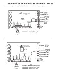
MOUNTING DIMENSIONS<strong>65E</strong>20 & <strong>65E</strong>40 MOUNTING7.00”1.70”3.62”1.75”.188 DIA.(4 SLOTS).344”SLOT DEPTHSIDE VIEW6.50”TOP VIEW<strong>65E</strong>60 MOUNTING9.00”2.27”7.50”.75”2.00”7/32” DIA.(4 SLOTS)6.30”6.70”NOTE:When mounting the control, allow clearance abovecomponents to prevent shortingSIDE VIEWTOP VIEWSIDE VIEWTOP VIEWCaution: Do not mount controller where ambient temperature is outside the range of -10° C (15° F) to 45° (115° F).INSTALLATIONBefore attempting to wire the control, make sure all power is disconnected. Recheck code designation to assure proper voltageis present for the control. Caution should be used in selecting proper size of hook-up wire for current and voltage drop. Note: thebattery and armature wire size on <strong>65E</strong> models must be a minimum of 12 gauge.HOOK-UP DIAGRAMSWARNING:DO NOT REVERSE POSITIVE AND NEGATIVE BATTERY LEADS. THIS WILL DAMAGE THE CONTROL.TO CHANGE MOTOR DIRECTION, INTERCHANGE THE POSITIVE AND NEGATIVE ARMATURE LEADS.Refer to the wiring diagrams below for proper connection of DC Voltage, Armature, and Speedpot wiring to the control.CAUTION !! TURN POWER OFF WHILE MAKING CONNECTIONS .To properly adjust the CURRENT LIMIT setting, a DC ammeter should be placed in series with the armature line. This meter canbe removed after the control is adjusted.2(continued)
(continued)-Motor+-+BatteryCustomer suppliedSPST switchCaution:Motor and battery wire mustbe a minimum of 12 ga. anda maximum of 6 ga.+ +P1<strong>65E</strong> SERIES HOOK-UP DIAGRAM-Battery (P1-1)-Arm (P1-2)No Connect (P1-3)+Battery (P1-4)+Arm (P1-5)Pot High (P2-1)Pot Wiper (P2-2)Pot Low (P2-3)Common (P2-4)Inhibit (P2-5)Current LimitP2WhiteRedOrangeI.R. Comp.AccelMax SpeedMin Speed5KýSpeedpotOptionalInhibit(see hook-upbelow)<strong>65E</strong> REVERSING HOOK-UP DIAGRAMCustomer supplied3PDT Center-offCenter-blocked switchRelays may be used in place of switch, but a neutral position must be providedto prevent plug reversing. Do not engage opposite direction until motor hascome to a complete stop. Failure to do so may result in damage to the control.Motor-Battery+CustomersuppliedSPST switchCaution:Motor and battery wire mustbe a minimum of 12 ga. anda maximum of 6 ga.+ +P1-Arm (P1-2)+Arm (P1-5)Using inhibit input - provide fast startstopby bypassing accel/decel circuit-Battery (P1-1)No Connect (P1-3)+Battery (P1-4)WhitePot High (P2-1)Pot Wiper (P2-2)Pot Low (P2-3)Common (P2-4)Inhibit (P2-5)Current LimitINHIBITING THE CONTROLP2RedOrangeI.R. Comp.AccelMax SpeedMin Speed5KýSpeedpotOptionalInhibit(see hook-upbelow)Inhibit via speedpot - provides starting andstopping through accel/decel parametersPot High (P2-1)Pot Wiper (P2-2)Pot Low (P2-3)Common (P2-4)Inhibit (P2-5)P2SPST Switchopen = runclose = stopPot High (P2-1)Pot Wiper (P2-2)Pot Low (P2-3)Common (P2-4)Inhibit (P2-5)P2WhiteRedOrangeSPST Switchopen = stopclose = run5KWSpeedpotNote: Always use a shielded cable when connecting to the inhibit terminal. The shield of the cable should connect to the Commonterminal of the control.TRIMPOT ADJUSTMENTSBefore the power is applied, the speed potentiometer and trimpots should be preset as follows:TRIMPOT PRESET1. Preset speedpot fully CCW, preset Max trimpot CW 1/2 way, preset Current Limit trimpot fully CW, preset Min trimpot fullyCCW, preset Accel trimpot CW 1/2 way, preset I.R. trimpot fully CW.DC power can now be applied to the system and the control adjusted as directed below:TRIMPOT ADJUSTMENT2. Increase the MIN trimpot in a clockwise direction until the desired minimum speed is reached.3. Turn the Speedpot fully clockwise and adjust the MAX trimpot until the desired maximum speed is reached.3(continued on following page)
(continued)4. Adjust the ACCEL trimpot to achieve the desired soft start time. CW rotation will increase accel time.5. Rotate the CURRENT LIMIT trimpot fully CCW until the motor begins to stall. Apply a full load to the motor. While motoris stalled adjust the CURRENT LIMIT trimpot CW until a desired current setting is obtained.6. Adjust I.R. trimpot CW 1/2 way. If motor RPM is inconsistent (jumpy), rotate I.R. trimpot CCW until rotation is stable.IN CASE OF DIFFICULTYIf a newly installed control will not operate, it is likely that a terminal or connection is loose. Check to make sure connections aresecure and correct. If the control is still inoperative, refer to the following chart for reference:PROBLEM POSSIBLE CAUSE(S) CORRECTIVE ACTIONMotor doesn’t run • Incorrect or no power Install proper service• Speedpot set at zeroRotate speedpot fully CW• Worn motor brushesReplace motor brushes• Current limit set too lowAdjust current limit trimpot CWMotor “hunts” • Max trimpot set too high See “Trimpot Adjustments” - page 3-4• I.R. Comp. trimpot set too high See “Trimpot Adjustments” - page 3-4Motor runs at “full speed” • Loose speedpot connections Secure all connectionsuncontrollable • Min. or Max. trimpots not properly adjusted See “Trimpot Adjustments” - page 3-4• Possible control failureSend to <strong>Dart</strong> <strong>Controls</strong>, Inc.Motor rotates in wrong direction • Motor armature hooked up backwards Reverse armature + and - leadsMotor stalls under a light load • Current limit trimpot improperly adjusted See “Trimpot Adjustments” - page 3-4MODEL SELECTIONINPUT VOLTAGE OUTPUT VOLTAGE CONTINUOUS CURRENT MODEL NUMBER12 VDC ± 15% 0 - 12 VDC 20 amps D.C. <strong>65E</strong>20-1212 VDC ± 15% 0 - 12 VDC 40 amps D.C. <strong>65E</strong>40-1212 VDC ± 15% 0 - 12 VDC 60 amps D.C. <strong>65E</strong>60-1224 VDC ± 15% 0 - 24 VDC 20 amps D.C. <strong>65E</strong>20*24 VDC ± 15% 0 - 24 VDC 40 amps D.C. <strong>65E</strong>40*24 VDC ± 15% 0 - 24 VDC 60 amps D.C. <strong>65E</strong>60*36 VDC ± 15% 0 - 36 VDC 20 amps D.C. <strong>65E</strong>20*36 VDC ± 15% 0 - 36 VDC 40 amps D.C. <strong>65E</strong>40*36 VDC ± 15% 0 - 36 VDC 60 amps D.C. <strong>65E</strong>60** 24 volt and 36 volt units with the same current ratings are interchangeable (ie. 24 volt unit will operate with 36 volt input anda 36 volt unit will operate with 24 volt input, same current rating).SPECIFICATIONS<strong>65E</strong>20 <strong>65E</strong>40 <strong>65E</strong>60Load current (continuous) 20 amps 40 amps 60 ampsSpeed adjustment5K Ω potentiometer or 0 to +10VDC input signalSpeed range 30 : 1Overload capacity200% for 10 seconds; 150% for one minuteCurrent limit adjustable100% to 200% of full motor load, up to continuous current rating (page 4)Accelerationadjustable - 0 to 10 secondsDecelerationnon-adjustable - 0.5 secondsMaximum speedadjustable - 50 to 100% of base speedMinimum speedadjustable - 30% of max speedConnectionsbarrier terminal block (12Ga. to a maximum 6 Ga.)Speed regulation1% of base speed via adjustable I.R. Compensation trimpotOperating temperature-10°C to +45°C (14°F to 113°F)Package configurationblack anodized aluminum extrusionInternal operating frequencyapproximately 1.6K HertzThermal protection N/A Current foldback at 80 o C. heatsink temperature4
+<strong>65E</strong>40 / <strong>65E</strong>60 PART PLACEMENT & LISTRESISTORSR1R2R3R4R5R6R7R8R9R10R11R12R13R14R15R16R17R18R19R20R21R22R23R24R25R26R27R28R29R30R31R32R33R34R35R36R37R38R39R40R41R42R43R44R45R46R47R48R49R50R51300& 5W47K470&47K470&10K20K MAX33K220K47K10K100K10K180K250K ACCEL20K 1/4W 1%470K300K47K5K MIN82K10K4.7K6.8K10K4.7K47K10K300K20K CUR. LIM.4.7K5K I.R. COMP100K47K2.7K22&22&22&22&22&22&47K1.2M150&5K SPEEDPOT*22K680K2.7K100K100K15KMISCELLANEOUSPCBP1 (-1 thru -5)P2 (-1 thru -5)RL1RL2RL3SW1CAPACITORSC1C2C3C4C5C6C7C8C9C10C11C12C13C14C15DIODED1D2D3D4D5D6D71N40051N40051N5349B1N963B1N914B1N5233B1N914BACTIVEDEVICESQ1Q2Q3Q4Q5Q6Q7Q8Q9Q1.1µF 63V.1µF 63V.22µF 100V.1µF 63V.1µF 63V.22µF 100V.1µF 63V.01µF 100V.01µF 100V47µF 16V1000µF 50V1000µF 50V.1µF 63V.1µF 63V.01µF 100VIRFZ44IRFZ44IRFZ44IRFZ44IRFZ44IRFZ44IRFZ44IRFZ44IRFZ44IRFZ44IC PACKAGESU1U2U3U440106 ICLM324 ICLM324 ICLM358 ICA-4-2519B PRINTED CIRCUIT BOARD5 POS. TERMINAL BLOCK5 POS. BARRIER TERMINAL STRIPRLB2508X RAILRLPRN910 RAILRLB25011XB RAIL67F080 TEMP .SWITCHH W L COM INH I.R. COMP ACCEL MAX MINR27P2-1 P2-2 P2-3 P2-4 P2-5CR33U1R20C2R32 C14 R15 R7R35R30C.LD5R8R19C13D6U4R49R16R34C9R50R29R48R17 R31C4U2R46C15D7R28Q6R41 C5R47 C3R51R11R22 R26D2Q5R12R25R24R18D3R21C6D1R2R44R43 SW1R40C7R23U3R6Q10R5C10R10R4 D4R39Q4R14 R3R42Q3RL3C8Q9R38R9R13RL1 RL2Q8Q2R37C12Q1R36++R1Q7C11P1-1 -B P1-2 -A +B P1-4 +A P1-5<strong>65E</strong>20-12CHANGES:<strong>65E</strong>20CHANGES:C12Q1Q2Q3Q4Q7Q9Q10R1R6R28R31R35R42R48DELETEDELETEDELETEDELETEDELETEDELETEDELETEDELETE10& 1W22K4.7K2.2K1K22K1KC12Q1Q2Q3Q4Q7Q9Q10R48DELETEDELETEDELETEDELETEDELETEDELETEDELETEDELETE1K<strong>65E</strong>40/60-12CHANGES:R1R6R31R35R42R4810& 1W22K2.2K1K22K1K* SPEEDPOT IS MOUNTED REMOTENOTE: ALL RESISTORS 1/8W UNLESS NOTED OTHERWISE5
CONTENIDOGARANTÍA 1CARACTERÍSTICAS REGULARES 1DIMENSIONES DEL CONTROL 1DIMENSIONES DE MONTAJE 2INSTALACIÓN 2DIAGRAMAS DE CONEXIÓN 2-3CÓMO INHIBIR EL CONTROL 3CALIBRACIÓN DE LA TERMINAL DE AJUSTE 3-4EN CASO DE DIFICULTADES 4SELECCIÓN DEL MODELO 4ESPECIFICACIONES 4LOCALIZACIÓN Y LISTA DE LAS PARTES DE LA SERIE <strong>65E</strong> 5ESQUEMA DE LA SERIE <strong>65E</strong> 6PROCEDIMIENTO DE REPARACIÓN Y LÍNEA DE PRODUCTOS CONTRAPORTADAGARANTÍA<strong>Dart</strong> <strong>Controls</strong>, Inc (DCI) garantiza que sus productos están libres de defectos en su material y mano de obra La solución exclusiva de estagarantía consiste en el reemplazo, por parte de la fábrica de DCI, de cualquier parte o partes de dicho producto, el cual deberá ser devueltodentro de un plazo de 12 meses posteriores a la entrega al comprador, directamente a la fábrica de DCI con todos los cargos detransportación prepagados y el cual DCI determine, a su propia satisfacción, que esté defectuoso Esta garantía no se extenderá a defectosen el ensamblado por otra parte que no sea DCI o algún artículo que haya sido reparado o alterado por otra parte que no sea DCI o acualquier artículo que DCI determine que se ha sometido a uso inapropiado DCI no asume ninguna responsabilidad por las característicasde diseño de cualquier unidad o su operación en algún circuito o ensamblaje Esta garantía sustituye a todas las otras garantías expresas oimplícitas; todas las otras responsabilidades u obligaciones por parte de DCI, incluyendo los daños de consecuencia, se excluyenexpresamente por la presenteNOTA: Revise cuidadosamente el control en búsqueda de daño que haya sido ocasionado durante el envío Reporte cualquier daño altransportista inmediatamente No intente operar el control del motor si el daño visible es evidente ya sea al circuito o a los componenteselectrónicosToda la información contenida en este manual tiene la intención de ser correcta, sin embargo la información y los datos en este manual estánsujetos a cambios sin ningún aviso DCI no establece garantías de ningún tipo con respecto a esta información o datos Además, DCI no esresponsable de ninguna omisión o error o de daño de consecuencia causados por el usuario del producto DCI se reserva el derecho derealizar cambios de fabricación, los cuales pueden no estar incluidos en este manualADVERTENCIALa instalación u operación inapropiada de este control puede causar lesión al personal, o que el control no funcione Elcontrol debe ser instalado de acuerdo con los códigos de seguridad Locales, Estatales y Nacionales ¡¡¡Asegúrese de que lafuente de energía esté desconectada antes de intentar reparar o remover algún componente!!! Si el punto para desconectarla energía está fuera del alcance de la vista, asegúrelo en la posición de desconectado y ponga una etiqueta para prevenir laaplicación de energía inesperada Solamente un electricista calificado o personal de servicio debe llevar a cabo lasactividades de resolución de problemas eléctricos o el mantenimiento eléctrico En ningún momento se debe comprobar lacontinuidad del circuito mediante el corto circuito de las terminales con un destornillador u otro dispositivo de metalCARACTERISTÍCAS REGULARESl Proporciona capacidad de velocidad variable suave para el equipo móvill Mantiene control de velocidad variable a medida que las baterías se descarganl Velocidad máxima, velocidad mínima, límite de corriente, compensación IR y aceleración ajustablesl La terminal de inhibición permite arranque y paro opcionales sin desconectar las líneas de la bateríal Se incluye el potenciómetro de velocidad, perilla y placa cuadrantel Aumenta el rango o tiempo de operación del equipo operado con batería mediante la alta eficienciaPara las series <strong>65E</strong>40 y <strong>65E</strong>60 solamente – El retorno automático del límite de corriente disminuye el límite decorriente a un 50% del punto de fijación cuando las temperaturas del disipador térmico llegan a 80 °C -proporciona protección contra el sobrecalentamientoDIMENSIONES DEL CONTROLMODELO ANCHURA LONGITUD PROFUNDIDAD PESOpulgadas (centímetros)1-SPoz. (gms.)<strong>65E</strong>20 3,7 (9,40) 7,0 (17,8) 1,70 (4,32) 10,5 (297)<strong>65E</strong>40 3,7 (9,40) 7,0 (17,8) 1,70 (4,32) 13,4 (379)<strong>65E</strong>60 6,7 (17,1) 9,0 (22,9) 2,27 (5,77) 34,0 (962)
DIMENSIONES DE MONTAJEMONTAJE para el <strong>65E</strong>20 y <strong>65E</strong>407.00”1.70”3.62”1.75”'0,188 DIA(4 RANURAS)PROFUNDIDAD DE LA RANURA0,344”MONTAJE para el <strong>65E</strong>606.50”9.00”2.27”7.50”.75”2.00”7/32” DIA.(4 RANURAS)6.30”6.70”NOTA:Cuando se monte el control, deje un espacio arriba de los componentespara prevenir cortocircuitos.VISTA LATERALPrecaución: No monte el control en situaciones en las cuales la temperatura ambiente se encuentre fueradel rango de –10 °C (15 °F) a 45° (115 °F)INSTALACIÓNAntes de intentar instalar el control con cables eléctricos, asegúrese de que la energía esté desconectada Revisenuevamente la designación de los códigos para asegurarse de que el voltaje adecuado esté presente para el controlSe debe utilizar precaución para seleccionar el tamaño adecuado del alambre de conexión para la caída (“drop”) decorriente y voltaje Nota: El tamaño del cable para la batería y el armazón en los modelos <strong>65E</strong> deben ser de unmínimo de calibre 12DIAGRAMAS DE CONEXIÓNADVERTENCIA:NO INVIERTA LAS CONEXIONES POSITIVAS Y NEGATIVAS DE LA BATERÍA ESTO DAÑARÁ AL CONTROL PARACAMBIAR LA DIRECCIÓN DEL MOTOR, INTERCAMBIE LAS CONEXIONES POSITIVAS Y NEGATIVAS DEL ARMAZÓNRefiérase a los diagramas de alambrado que se encuentran más adelante para la conexión apropiada del alambradodel Voltaje de DC, Armazón y Terminal Controladora de Velocidad al Control¡¡PRECAUCIÓN!! DESCONECTE LA ENERGÍA CUANDO ESTÉ HACIENDO LAS CONEXIONESPara seleccionar apropiadamente el ajuste del LÍMITE DE CORRIENTE (CURRENT LIMIT) se debe colocar un amperímetrode DC en serie con la línea del armazón Este medidor puede ser removido después de que el control sea ajustado2-SPVISTA SUPERIOR(continúa)
(continúa)-Motor+-+BateriaInterruptor SPSTproporcionado por elclientePrecaucion: 'El alambre del motor y della bateria ' debe ser de unminimo ' de calibre 12 y unmaximo ' de calibre 6.Interruptor proporcionadopor el cliente 3PDTCentral-apagado, CentralbloqueadoDIAGRAMA DE CONEXIÓN SERIE <strong>65E</strong>+ +P1-Bateria (P1-1)-Brazo (P1-2)No se conecta (P1-3)+Bateria (P1-4)+Brazo (P1-5)P2Terminal de vel. alto (P2-1)Terminal de vel. movil ' (P2-2)Terminal de vel. baja (P2-3)Comun ' (P2-4)Inhibicion ' (P2-5)Limite decorrienteLos relevadores se pueden utilizar en lugar de interruptores, pero una posicion 'neutral se debe proporcionar para prevenir la inversion ' de los enchufes. Noactive la direccion ' opuesta hasta que el motor se haya detenido por completo.El no hacerlo asi ' puede resultar en dano ~ al control.BlancoBlancoRojoAnaranjadoComp. I.R.Aceler.Terminal de controlde velocidad 5KWVelocidad max.Inhibicion 'opcional(ver la conexion 'mas ' adelante)Velocidad minimaDIAGRAMA DE CONEXIÓN REVERSA SERIE <strong>65E</strong>MotorUtilizando la entrada para inhibicion'- proporcionarapido ' encendido-apagado mediante la desviacion ' delcircuito de acel/desacel.Terminal de vel. alto (P2-1)Terminal de vel. movil ' (P2-2)Terminal de vel. baja (P2-3)Comun ' (P2-4)Inhibicion ' (P2-5)P2-Bateria+InterruptorSPSTproporcionadopor el clientePrecaucion: 'El alambre del motor y della bateria ' debe ser de unminimo ' de calibre 12 y unmaximo ' de calibre 6.+ +P1Terminal de controlde velocidad 5KWP2Terminal de vel. alto (P2-1)Terminal de vel. movil ' (P2-2) Rojo-Bateria (P1-1) Terminal de vel. baja (P2-3) AnaranjadoComun ' (P2-4)Inhibicion ' (P2-5)Inhibicion '-Brazo (P1-2)opcional(ver laNo se conecta (P1-3)Comp. I.R. conexion 'mas ' adelante)+Bateria (P1-4)Aceler.Limite de+Brazo (P1-5)corrienteVelocidad max.Velocidad minimaCÓMO INHIBIR EL CONTROLTerminal de vel. alto (P2-1)Interruptor SPST Terminal de vel. movil ' (P2-2)abierto = en operacion 'Terminal de vel. baja (P2-3)cerrado = apagadoComun ' (P2-4)Inhibicion ' (P2-5)P2Inhibicion ' via la terminal de control develocidad-proporciona encendido y apagadomediante los parametros ' de acel/desacel.BlancoRojoAnaranjadoInterruptor SPSTabierto = apagadocerrado = enoperacion'Terminal decontrol develocidad5KWNota: Siempre utilice un cable blindado cuando se conecte a la terminal de inhibición El blindaje del cable se debe conectar a la terminal común del controlCALIBRACIÓN DE LA TERMINAL DE AJUSTE DE CIRCUITO (TRIMPOT)Antes de que se aplique la energía, el potenciómetro de velocidad y las terminales de ajuste de circuito (trimpots) deben estar prefijadas de lasiguiente manera:PREFIJACIÓN DE LA TERMINAL DE AJUSTE DE CIRCUITO (TRIMPOT)1 Prefije la terminal de control de velocidad (speedpot) completamente en el sentido contrario de las manecillas del reloj, prefije la terminal de ajuste de circuito(trimpot) “Max” a media de la capacidad en el sentido de las manecillas del reloj, prefije la terminal de ajuste de circuito (trimpot) de “Current Limit”completamente en el sentido de las manecillas del reloj, prefije la terminal de ajuste de circuito (trimpot) “Min” completamente en el sentido contrario de lasmanecillas del reloj, prefije la terminal de ajuste de circuito (trimpot) “Accel” a media de la capacidad en el sentido de las manecillas del reloj, prefije laterminal de ajuste de circuito (trimpot) “IR” completamente en el sentido de las manecillas del relojLa energía de DC ahora se puede aplicar al sistema y al control ajustado como se indica a continuación:CALIBRACIÓN DE LA TERMINAL DE AJUSTE DE CIRCUITO (TRIMPOT)2 Aumente la terminal de ajuste de circuito (trimpot) MIN en el sentido de las manecillas del reloj hasta que se alcance la velocidad mínima deseada3 Gire la terminal de control de velocidad (speedpot) completamente en el sentido de las manecillas del reloj y fije la terminal de ajuste de circuito (trimpot) MAXhasta que se alcance la velocidad máxima deseada3-SP(continúa en la siguiente página)
(continúa)4 Fije la terminal de ajuste de circuito (trimpot) ACCEL para lograr alcanzar el tiempo de inicio suave deseado La rotación en el sentido de las manecillas delreloj incrementará el tiempo de aceleración5 Gire la terminal de ajuste de circuito (trimpot) CURRENT LIMIT completamente en sentido contrario de las manecillas del reloj hasta que el motor comience adetenerse Aplique una carga completa al motor Mientras que el motor esté comenzando a detenerse mueva la terminal de ajuste de circuito (trimpot)CURRENT LIMIT en sentido de las manecillas del reloj hasta que una posición de corriente deseada sea obtenida6 Mueva la terminal de ajuste de circuito (trimpot) “IR” en sentido de las manecillas del reloj a media capacidad Si las RPM del motor son inconsistentes(inestables), gire la terminal de ajuste de circuito (trimpot) “IR” en sentido contrario a las manecillas del reloj hasta que la rotación sea estableEN CASO DE DIFICULTADESSi un control nuevamente instalado no opera, es probable que una terminal o conexión esté floja Verifique para asegurarse de que lasconexiones estén seguras y correctas Si el control aún no está operando, refiérase a la siguiente tabla como referencia:PROBLEMA CAUSA(S) POSIBLE(S) ACCIÓN CORRECTIVAEl motor no funciona • Energía incorrecta o ninguna energía Instale el servicio apropiadamente• Terminal de control de velocidad (speedpot) fijada a 0Gire la terminal de control de velocidad en sentido horario• Cepillos del motor desgastadosReemplace los cepillos de motor• El límite de corriente está fijado demasiado bajoMueva la terminal de ajuste de circuito (trimpot) "current limit" en sentido horarioEl motor "oscila" • Terminal de ajuste de circuito (trimpot) Máx fijada Véase "Calibración de la Terminal de Ajuste de Circuito (Trimpot)" páginas 3-4demasiado alto• Terminal de ajuste de circuito (trimpot) "IR Comp" fijada Véase "Calibración de la Terminal de Ajuste de Circuito (Trimpot)" páginas 3-4demasiado altoEl motor funciona a "toda velocidad" • Conexiones de la terminal de control de velocidad (speedpot) Asegure todas las conexionessin control flojas• Los trimpots min o máx no están ajustados adecuadamente Véase "Calibración de la Terminal de Ajuste de Circuito (Trimpot)" páginas 3-4• Posible falla del controlEnvíese a <strong>Dart</strong> <strong>Controls</strong>, IncEl motor gira en la dirección • El armazón del motor está conectado al revés Invierta las conexiones + y - del armazónequivocadaEl motor se detiene con una carga • La terminal de ajuste de circuito (trimpot) "current limit" estáVéase "Calibración de la Terminal de Ajuste de Circuito (Trimpot)" páginas 3-4ligera ajustada inadecuadamenteSELECCIÓN DEL MODELOVOLTAJE DE ENTRADA VOLTAJE DE SALIDA CORRIENTE CONTINUA NÚMERO DE MODELO12 VDC ± 15% 0 - 12 VDC 20 amps D.C. <strong>65E</strong>20-1212 VDC ± 15% 0 - 12 VDC 40 amps D.C. <strong>65E</strong>40-1212 VDC ± 15% 0 - 12 VDC 60 amps D.C. <strong>65E</strong>60-1224 VDC ± 15% 0 - 24 VDC 20 amps D.C. <strong>65E</strong>20*24 VDC ± 15% 0 - 24 VDC 40 amps D.C. <strong>65E</strong>40*24 VDC ± 15% 0 - 24 VDC 60 amps D.C. <strong>65E</strong>60*36 VDC ± 15% 0 - 36 VDC 20 amps D.C. <strong>65E</strong>20*36 VDC ± 15% 0 - 36 VDC 40 amps D.C. <strong>65E</strong>40*36 VDC ± 15% 0 - 36 VDC 60 amps D.C. <strong>65E</strong>60** Las unidades de 24 voltios y 36 voltios con la misma clasificación de corriente son intercambiables (es decir, la unidad de 24 voltios operará conuna entrada de 36 voltios y la unidad de 36 voltios operará con una entrada de 24 voltios de la misma clasificación de corriente)ESPECIFICACIONES<strong>65E</strong>20 <strong>65E</strong>40 <strong>65E</strong>60Corriente de carga (continua) 20 amps 40 amps 60 ampsAjuste de la velocidadpotenciómetro 5K omhios o señal de entrada de 0 a + 10VDCRango de la velocidad 30 : 1Capacidad de sobrecarga200% por 10 segundos; 150% por un minutoLímite de corriente ajustable100-200% de la carga completa del motor, hasta la clasificación de la corriente continua (p. 4)Aceleraciónajustable - 0 a 10 segundosDesaceleraciónnon-ajustable - 0,5 segundosVelocidad máximaajustable - 50 a 100% de la velocidad de baseVelocidad mínimaajustable - 30% de velocidad máximaConexiones bloque terminal de barrera (calibre 12 a un máximo de calibre 6)Regulación de la velocidad1% de la velocidad de base vía trimpot ajustable de Compensasión I.R.Temperatura de operación-10 °C a +45 °C (14 °F a 113 °F)Configuración del paqueteextrusión de aluminio anodizada negraFrecuencia de operación internaaproximadamente 1,6K HertzProtección térmica N/A retorno de corriente a 80 °C de temperatura del disipador térmico4-SP
+LOCALIZACIÓN Y LISTA DE LAS PARTES PARA <strong>65E</strong>40 / <strong>65E</strong>60RESISTORESR1R2R3R4R5R6R7R8R9R10R11R12R13R14R15R16R17R18R19R20R21R22R23R24R25R26R27R28R29R30R31R32R33R34R35R36R37R38R39R40R41R42R43R44R45R46R47R48R49R50R51300 5W47K47047K47010K20K MAX.'33K220K47K10K100K10K180K250K ACEL.20K 1/4W 1%470K300K47K5K MIN.'82K10K4.7K6.8K10K4.7K47K10K300K20K LIM. ' COR.4.7K5K COMP I.R.100K47K2.7K22222222222247K1.2M150TERM. CONT. VEL. 5K *22K680K2.7K100K100K15KMISCELANEOSCONDENSADORESC1C2C3C4C5C6C7C8C9C10C11C12C13C14C15DIODOSD1D2D3D4D5D6D71N40051N40051N5349B1N5242B1N914B1N5233B1N914BDISPOSITIVOSACTIVOSQ1Q2Q3Q4Q5Q6Q7Q8Q9Q10.1µF 63V.1µF 63V.22µF 100V.1µF 63V.1µF 63V.22µF 100V.1µF 63V.01µF 100V.01µF 100V47µF 16V1000µF 50V1000µF 50V.1µF 63V.1µF 63V.01µF 100VIRFZ44IRFZ44IRFZ44IRFZ44IRFZ44IRFZ44IRFZ44IRFZ44IRFZ44IRFZ44PAQUETES ICU1U2U3U440106 ICLM324 ICLM324 ICLM358 ICPCBA-4-2519E TABLERO DE CIRCUITO IMPRESOP1 (-1 hasta -5) BLOQUE TERMINAL DE 5 POS.P2 (-1 hasta -5) BANDA TERMINAL DE BARRERA DE 5 POS.RL1RLB2508X CARRILRL2RLPRN910 CARRILRL3RLB25011XB CARRILSW167F080 INTERRUPT. TEMP.H W L COM INH I.R. COMP ACCEL MAX MINR27P2-1 P2-2 P2-3 P2-4 P2-5C1R33U1R20C2R32 C14 R15 R7R35R30D5C.L.R8R19C13D6U4R49R16R34R29C9R50R48R17 R31U2R46C4 C15R28D7R41 C5Q6R47 C3R51R11R22 R26D2Q5R12R25R18D3R24R21C6D1R2R44R43 SW1R40C7R23U3C10R10R39Q4Q3C8R38R9RL1 RL2R37C12Q2+Q1R1R36+C11P1-1 -B P1-2 -A +B P1-4 +A P1-5+ +Q10R6R5R4 D4R14 R3R42RL3Q9R13Q8Q7CAMBIOS AL<strong>65E</strong>20-12CAMBIOS AL<strong>65E</strong>20C12Q1Q2Q3Q4Q9Q10R1R6R28R31R35R42R48BORRARBORRARBORRARBORRARBORRARBORRARBORRAR10 1W22K4.7K2.2K1K22K1KC12Q1Q2Q3Q4Q9Q10R48BORRARBORRARBORRARBORRARBORRARBORRARBORRAR1KCAMBIOS AL<strong>65E</strong>40/60-12R1R6R31R35R42R4810 1W22K2.2K1K22K1K* LA TERMINAL DE CONTROL DE VELOCIDAD (SPEEDPOT)SE MONTA REMOTAMENTENOTA: TODOS LOS RESISTORES SON DE 1/8W AMENOS QUE SE HAGA NOTAR DE OTRO MODO5-SP
ESQUEMA DE LA SERIE <strong>65E</strong>+12VALTAP2-1R45TERM. CONT.VEL. REMOTA5KMOVIL'P2-2BAJAP2-3R20MIN.5KR1947KR18300KC5.1µF63V910-U3-3+8-+U3-2+12V411'675NOTAS:U1 - 40106U2 - LM324U3 - LM324U4 - LM358'TODAS LAS RESISTENCIAS SON DE 1/8W A MENOS QUESE HAGA NOTAR DE OTRO MODO-+-+CWCOMP2-4INHIBICIONP2-5 'I.R.R325KcwD11N4005+12VR17470KACELER.CWR1620K1/2W1%R15250KR14180K+12VR2510KR264.7KC4.1µF63V14U2-41213C3.22µF100VR12100KR1310K109R29300KC6.22µF100VR9220KR234.7K+U2-38C9.01µF100V-R246.8K+12VR2810KSW1INTERRUPT. TEMP.CWC.L.R3020KR314.7KR47680K56+12VD21N4005C1047µF16VD31N5349BR247K+12VR1047K32+-4U3-1111R1110KC7.1µF63VR2210KU2-279 8U1-41R33100KU2-132C2.1µF63VR352.7KC1.1µF63V+BP1-4C111000uF50VC121000uF50VP1-5P1-2MOTOR+A-AGQ7IRFZ44 DSGQ8IRFZ44 DSGQ9IRFZ44 DSGQ10IRFZ44 DSC8.01µF100V1+12VU1-1143 4U1-25 6U1-3211 10U1-513 12U1-67R3447KR3622R3722R3822R3922R4022R4122GGGGGGQ1IRFZ44Q2IRFZ44Q3IRFZ44Q4IRFZ44Q5IRFZ44Q6IRFZ44RLINEADSDSDSDSDSDSP1-1-B+--+P1-3N.C.+12V23+81U4-14R4247KR44150cwMAX.R720K+12VD41N5242BR833K14U3-41213R3470R610KR447KR5470+12VR431.2MR13005W--C14.1µF63VR50100KC13.1µF63VR49100KR2182KR2747KR4622K+C15.01µF100VD51N914B7U4-265R482.7KD71N914BR5115K- BRAZOD61N5233BCAMBIOS AL<strong>65E</strong>40/60-12R1R6R31R35R42R48C12Q1Q2Q3Q4Q9Q10R4810 1W22K2.2K1K22K1KCAMBIOS AL<strong>65E</strong>20-12C12Q1Q2Q3Q4Q9Q10R1R6R28R31R35R42R48BORRARBORRARBORRARBORRARBORRARBORRARBORRAR10 1W22K4.7K2.2K1K22K1KCAMBIOS AL<strong>65E</strong>20BORRARBORRARBORRARBORRARBORRARBORRARBORRAR1K6-SP
TABLE DES MATIERESGARANTIE ........................................................................................................................................................... 1CARACTERISTIQUES STANDARD .................................................................................................................... 1DIMENSIONS DU BOITIER DE CONTROLE ........................................................................................................................... 1COTES DE MONTAGE ............................................................................................................................................................ 2INSTALLATION ........................................................................................................................................................................ 2SCHEMAS DE RACCORDEMENT ....................................................................................................................................... 2-3INHIBITION DU CONTROLE ..................................................................................................................................................... 3REGLAGES DU POTENTIOMETRE ..................................................................................................................................... 3-4EN CAS DE DIFFICULTES ...................................................................................................................................................... 4CHOIX DU MODELE ................................................................................................................................................................ 4SPECIFICATIONS .................................................................................................................................................................... 4SERIE <strong>65E</strong> LISTE DE PIECES ET EMPLACEMENT ............................................................................................................... 5SCHEMA SERIE <strong>65E</strong> ............................................................................................................................................................... 6PROCEDURE DE REPARATION ET GAMME ................................................................................ COUVERTURE ARRIEREGARANTIE<strong>Dart</strong> <strong>Controls</strong>, Inc. (DCI) garantit que ses produits sont indemnes de défauts de matière et de main d’œuvre. Le seul recours sous le couvertde cette garantie est le remplacement en usine par DCI de toute pièce ou partie du produit qui sera renvoyée à l’usine DCI dans les 12 moissuivant la livraison à l’acheteur, tous frais de transport payés, et qui sera estimée être défectueuse par DCI. Cette garantie ne couvre pas lesdéfauts d’assemblage par d’autres que DCI, ou tout article qui a été réparé ou modifié par d’autres que DCI, ou tout article que DCI estimeraavoir été sujet à usage incorrect. DCI n’assume aucune responsabilité pour les caractéristiques du concept de n’importe quel composant nipour son fonctionnement dans tout circuit ou ensemble. Cette garantie remplace toute autre garantie implicite ou explicite; toutes autresresponsabilités ou obligations de la part de DCI y compris dommages secondaires sont ici expressément exclus.NOTE : Vérifiez soigneusement que le régulateur n’ait pas subi de dégâts durant le transport. Signalez immédiatement tout dégât autransporteur. N’essayez pas d’utiliser l’entraînement si des dégâts au circuit ou aux composants électroniques sont évidents.Toutes les informations de ce manuel sont supposées être correctes, toutefois, les informations et données comprises dans ce manuelpeuvent être modifiées sans préavis. DCI n’offre aucune garantie d’aucune sorte qui couvre les informations et données. De plus, DCI neprend pas la responsabilité pour les omissions ou erreurs ou pour les dommages secondaires causés par l’utilisateur de ce produit. DCI seréserve le droit de procéder à des changements de fabrication qui pourraient ne pas être compris dans ce manuel.AVERTISSEMENTUne installation ou une opération incorrecte de ce régulateur peuvent causer des blessures au personnelou une panne du régulateur. Ce régulateur doit être installé suivant les codes de sécurité locaux et nationaux. Assurez-vous quel’alimentation électrique est coupée avant de procéder à un entretien ou d’enlever un composant quelconque !!! Si le point deraccordement électrique est hors de vue, verrouillez-le en position déconnectée et placez-y une étiquette pour éviter une applicationintempestive de courant. Seul un électricien ou un membre du personnel d’entretien est qualifié pour procéder à une recherche depanne ou à un entretien. En aucun cas il ne faut vérifier l’ouverture d’un circuit en utilisantun tournevis ou autre instrument métallique pour court-circuiter les bornes.lllllllCARACTERISTIQUES STANDARDOffre aux équipements mobiles la possibilité d’un contrôle souple de la vitesseMaintient le contrôle de la vitesse variable même lorsque les batteries se déchargentRéglage de la vitesse maximum et minimum, de la limite de courant, de la compensation I.R. etd’accélérationLa borne d’inhibition permet un démarrage/arrêt facultatif sans interruption des lignes de batteriesPotentiomètre de vitesse avec bouton et cadran comprisGrâce à son haut rendement, améliore la portée ou la durée de vie des équipements sur batteriesSéries <strong>65E</strong>40 et <strong>65E</strong>60 uniquement — la réduction automatique de la limite de courant diminue cettelimite de 50% du point de réglage lorsque le puits de chaleur atteint 80°C.—assure une protectionDIMENSIONS DU BOITIER DE CONTROLEMODELE LARGEUR LONGUEUR PROFONDEUR POIDSpouces (cm)oz. (g)<strong>65E</strong>20 3,7 (9,40) 7,0 (17,8) 1,70 (4,32) 10,5 (297)<strong>65E</strong>40 3,7 (9,40) 7,0 (17,8) 1,70 (4,32) 13,4 (379)<strong>65E</strong>60 6,7 (17,1) 9,0 (22,9) 2,27 (5,77) 34,0 (962)1-FR
COTES DE MONTAGEMontage des <strong>65E</strong>20 et <strong>65E</strong>407.00”1.70”3.62”1.75”0,188 DIA.(4 ENCOCHES)PROFONDEUR ENCOCHE0,344”6.50”VUE DE CÔTÉVUE DU DESSUSMONTAGE DU <strong>65E</strong>609.00”2.27”7.50”.75”2.00”7/32” DIA.(4 ENCOCHES)6.30”6.70”NOTE:Lors du montage du regulateur, ' laissez du jeu au-dessus descomposants pour eviter ' les courts-circuits.VUE DE CÔTÉVUE DU DESSUSAttention: N'installez pas le régulateur dans un endroit où la température ambiante est hors de la fourchette de -10°C (15° F) à +45°C (115° F).INSTALLATIONAvant d’essayer de câbler le régulateur, assurez-vous que le courant est coupé. Vérifiez à nouveau le code du produitpour vous assurer que la tension correcte est appliquée au régulateur. Faites attention en choisissant la dimension descâbles de connexion pour éviter les chutes de tension et pertes de courant. Note : La dimension des câbles de batterieet d’armature du modèle <strong>65E</strong> doit être au minimum de calibre 12.SCHEMAS DE RACCORDEMENTAVERTISSEMENT:N’INVERSEZ PAS LES CABLES POSITIFS ET NEGATIFS DE LA BATTERIE. CECI ENDOMMAGERAIT LEREGULATEUR. POUR CHANGER LA DIRECTION DE ROTATION DU MOTEUR, INVERSEZ LA POLARITE DESCABLES DE L’ARMATURE.Consultez les schémas de raccordement ci-dessous pour les connexions correctes de la tension CC, de l’armature etpour la câblage correct du potentiomètre au régulateur.ATTENTION : COUPEZ LE COURANT LORS DES RACCORDEMENTS.Pour obtenir un réglage correct de la LIMITE DE COURANT, un ampèremètre CC doit être placé en série dans la ligned’armature. Cet ampèremètre peut être enlevé après réglage.2-FR(suite page suivante)
(cont.)5. Tournez le potentiomètre Limite courant à fond sens antihoraire jusqu’à ce que le moteur commence à caler. Mettez le moteur souscharge maximum. Avec le moteur calé, réglez le potentiomètre Limite courant dans le sens horaire jusqu’à ce que le réglage voulu ducourant soit obtenu.6. Réglez le potentiomètre IR à mi-course dans le sens horaire. Si la vitesse du moteur est irrégulière (à-coups), tournez le potentiomètre IRdans le sens antihoraire jusqu’à ce que la vitesse se stabilise.EN CAS DE DIFFICULTESSi un régulateur nouvellement installé ne fonctionne pas, il est probable qu’une borne ou un raccord soit lâche. Vérifiez que les raccords sontserrés et corrects. Si le régulateur ne fonctionne toujours pas, consultez le tableau ci-dessous :PROBLEME CAUSE(S) POSSIBLE(S) REMEDELe moteur ne tourne pas • Manque de tension ou aucune tension Corrigez l'alimentation• Pot. vitesse sur zéroTournez le pot. vitesse à fond sens horaire• Balais du moteur usésRemplacez les balais• Limite courant trop basseRéglez le pot. limite courant dans le sens horaireLe moteur pompe • Pot. Max. réglé trop haut Voir “Réglages Pot.” - page 3-4• IPot. comp. IR réglé trop haut Voir “Réglages Pot.” - page 3-4Le moteur tourne à vitesse • Connexions pot. vitesse lâches Serrez les connexionsmax. hors de contrôle • Pot. Min. ou Max. mal réglés Voir “Réglages Pot.” - page 3-4• Panne possible du régulateurRenvoyez-le chez <strong>Dart</strong> <strong>Controls</strong>, Inc.Le moteur tourne dans le mauvais sens • Armature moteur connectée à l'envers Inversez les fils + et - de l'armatureLe moteur cale sous faible charge • Pot. limite courant mal réglé Voir “Réglages Pot.” - page 3-4CHOIX DU MODELETENSION ENTREE TENSION SORTIE COURANT REGIME NUMERO MODELE12 V CC ± 15% 0 - 12 V CC 20 amps CC <strong>65E</strong>20-1212 V CC ± 15% 0 - 12 V CC 40 amps CC <strong>65E</strong>40-1212 V CC ± 15% 0 - 12 V CC 60 amps CC <strong>65E</strong>60-1224 V CC ± 15% 0 - 24 V CC 20 amps CC <strong>65E</strong>20*24 V CC ± 15% 0 - 24 V CC 40 amps CC <strong>65E</strong>40*24 V CC ± 15% 0 - 24 V CC 60 amps CC <strong>65E</strong>60*36 V CC ± 15% 0 - 36 V CC 20 amps CC <strong>65E</strong>20*36 V CC ± 15% 0 - 36 V CC 40 amps CC <strong>65E</strong>40*36 V CC ± 15% 0 - 36 V CC 60 amps CC <strong>65E</strong>60** Les groupes de 24 V et de 36 V avec le même courant nominal sont interchangeables par ex. un groupe de 24 Vfonctionnera avec une tension d'entrée de 36 V et un groupe de 36 V fonctionnera avec une tension d'entrée de 24 V,même courant nominal).SPECIFICATIONS<strong>65E</strong>20 <strong>65E</strong>40 <strong>65E</strong>60Courant en charge (régime) 20 A 40 A 60 ARéglage vitessePotentiomètre 5 kΩ ou signal d'entrée de 0 à 10 V CCGamme vitesse 30 à 1Capacité surcharge200% pendant 10 sec.; 150% pendant 1 minuteLimite courantRéglable de 100% à 200% de la charge totale du moteur jusqu'au courant de régime (p.4)AccélérationRéglable - 0 to 10 secondsDécélérationNon réglable - 0,5 sec.Vitesse maximumRéglable de 50% à 100% de la vitesse de baseVitesse minimumRéglable - 30% de la vitesse maximumRaccordementsBarrette connexion (12 gauge à max. 6 gauge)Régulation vitesse1% de la vitesse de base par pot. de compensation IR réglableTempérature fonctionnement-10°C à +45°C (14°F to 113°F)Configuration extérieureProfilé extrudé aluminium anodisé noirFréquence interne opérationEnviron 1,6 KhzProtection thermique S/O Réduction du courant à partir d'une température de 80°C du puits de chaleur4-FR
+<strong>65E</strong>40 / <strong>65E</strong>60 - LISTE DES PIECES ET EMPLACEMENTRESISTANCESR1R2R3R4R5R6R7R8R9R10R11R12R13R14R15R16R17R18R19R20R21R22R23R24R25R26R27R28R29R30R31R32R33R34R35R36R37R38R39R40R41R42R43R44R45R46R47R48R49R50R51P2 (-1 a -5)''300 5W47K47047K47010K20K MAX.33K220K47K10K100K10K180K250K ACCEL.20K 1/4W 1%470K '300K47K5K MIN.82K10K4.7K6.8K10K4.7K47K10K300K20K LIM. CUR.4.7K5K COMP I.R.100K47K2.7K22222222222247K1.2M150POT. VITESSE 5K *22K680K2.7K100K100K15KDIVERSPCBP1 (-1 a -5)RL1RL2RL3SW1CONDENSATEURSC1C2C3C4C5C6C7C8C9C10C11C12C13C14C15DIODESD1D2D3D4D5D6D7' 'ACTIFS1N40051N40051N5349B1N5242B1N914B1N5233B1N914BELEMENTSQ1Q2Q3Q4Q5Q6Q7Q8Q9Q10.1µF 63V.1µF 63V.22µF 100V.1µF 63V.1µF 63V.22µF 100V.1µF 63V.01µF 100V.01µF 100V47µF 16V1000µF 50V1000µF 50V.1µF 63V.1µF 63V.01µF 100VIRFZ44IRFZ44IRFZ44IRFZ44IRFZ44IRFZ44IRFZ44IRFZ44IRFZ44IRFZ44ENSEMBLES ICU1U2U3U440106 ICLM324 ICLM324 ICLM358 ICA-4-2519E TABLEAU DE CIRCUIT IMPRIMEBORNE RACCORD DE 5 POS.BANDE TERMINALE DE BARRIERE DE 5 POS. 'RLB2508X RAILRLPRN910 RAIL'RLB25011XB RAIL67F080 INTERRUPT. THERM.H W L COM INH I.R. COMP ACCEL MAX MINR27P2-1 P2-2 P2-3 P2-4 P2-5C1R33U1R20C2R32 C14 R15 R7R35R30D5C.L.R8R19C13D6U4R49R16R34R29C9R50R48R17 R31U2R46C4 C15R28D7R41 C5Q6R47 C3R51R11R22 R26D2Q5R12R25R18D3R24R21C6D1R2R44R43 SW1R40C7R23U3C10R10R39Q4Q3C8R38R9RL1 RL2R37C12Q2+Q1R1R36+C11P1-1 -B P1-2 -A +B P1-4 +A P1-5+ +Q10R6R5R4 D4R14 R3R42RL3Q9R13Q8Q7CHANGEMENTSAU <strong>65E</strong>20-12CHANGEMENTSAU <strong>65E</strong>20C12Q1Q2Q3Q4Q9Q10R1R6R28R31R35R42R48ANNULERANNULERANNULERANNULERANNULERANNULERANNULER10 1W22K4.7K2.2K1K22K1KC12Q1Q2Q3Q4Q9Q10R48ANNULERANNULERANNULERANNULERANNULERANNULERANNULER1KCHANGEMENTSAU <strong>65E</strong>40/60-12R1R6R31R35R42R4810 1W22K2.2K1K22K1K* LE POTENTIOMETRE VITESSE EST MONTE A DISTANCENOTE: TOUTES LES RESISTANCES SONT 1/8W ' ' SAUFINDICATION CONTRAIRE5-FR
6-FRSCHEMA SERIE <strong>65E</strong>''TOUTES LES RESISTANCES SONT 1/8W SAUF INDICATION CONTRAIRENOTES:U1 - 40106U2 - LM324U3 - LM324U4 - LM358+12V114BALAIP2-2+12VR18300KBASP2-3HAUTP2-1R20MIN.5KR1947KR45POT. VIT. ADISTANCE5KC5.1µF63V+- U3-39108+-U3-2567+-+-141213C3.22µF100VR29300KC.L.R3020KSW1INTERRUPT. TEMP.R314.7K+12VR2810K123R264.7KR2510K+12VD11N4005R4122-BR4022R3922R3822R3722R3622Q6IRFZ44Q5IRFZ44Q4IRFZ44Q3IRFZ44Q2IRFZ44Q1IRFZ44R3447KQ7IRFZ44 D SGQ8IRFZ44 D SGQ9IRFZ44 D SGQ10IRFZ44 D SGMOTEURP1-2P1-5+BP1-4D21N4005R247KD31N5349B+12VC1047µF16VDSGDSGDSGDSGDSGDSGP1-1-A+AU2-1U2-413 12U1-611 10U1-55 6U1-33 4U1-21142U1-19 8U1-4C1.1µF63V7+12VRLIGNE+76U2-25-R2210KR352.7KC2.1µF63VR33100KI.R.R325KcwCW+-U2-31098C9.01µF100VR246.8KR234.7KC4.1µF63VCWR14180KR12100KR1310KR1620K1/2W1%R17470K+12VR15250KCWACCEL.C121000uF50VC111000uF50VC6.22µF100V+12V114+-U3-1321C8.01µF100VC7.1µF63VR9220KR1047KR1110KR47680KINHIBITIONP2-5COMP2-4+-141213U3-4R720KcwMAX.R447KR610KR833KR3470R5470R13005WN.C.P1-3D41N5242BR44150+12VR431.2MR4247K+12V+12V48-+U4-1231R49100KC14.1µF63VR50100KR2182KC13.1µF63VR2747KC15.01µF100V-+765U4-2D51N914BR4622KR482.7KD71N914B- ARMATURED61N5233BR5115KR1R6R31R35R42R4810 1W22K2.2K1K22K1KC12Q1Q2Q3Q4Q9Q10R48ANNULERANNULERANNULERANNULERANNULERANNULERANNULER1KC12Q1Q2Q3Q4Q9Q10R1R6R28R31R35R42R48ANNULERANNULERANNULERANNULERANNULERANNULERANNULER10 1W22K4.7K2.2K1K22K1KCHANGEMENTS AU<strong>65E</strong>20CHANGEMENTS AU<strong>65E</strong>20-12CHANGEMENTS AU<strong>65E</strong>40/60-12
REPAIR PROCEDUREIn the event that a Product manufactured by <strong>Dart</strong> <strong>Controls</strong> Incorporated (DCI) is in need ofrepair service, it should be shipped, freight paid, to: <strong>Dart</strong> <strong>Controls</strong>, Inc., 5000 W. 106th Street,Zionsville, IN. 46077, ATTN: Repair Department.Those orders received from anyone without and existing account with DCI will need to specifyif they will be paying COD or Credit Card (Master Card or Visa). This information is requiredbefore work can begin. If you have an account with <strong>Dart</strong> your order will be processed accordingto the terms listed on your account.Completed repairs are returned with a Repair Report that states the problem with the controland the possible cause. Repair orders are returned via UPS Ground unless other arrangementsare made. If you have further questions regarding repair procedures, contact your <strong>Dart</strong> <strong>Controls</strong>,Inc. at 317-733-2133 Ext.460.YOUR MOTION SYSTEMS SOLUTION PROVIDER125D SERIESAC INPUT - VARIABLE DC OUTPUT1/50 HP through 1.0 HP250G SERIESAC INPUT - VARIABLE DC OUTPUT1/50 HP through 2.0 HP65 SERIESDC INPUT - VARIABLE DC OUTPUTCURRENT RATINGS OF 20, 40, AND60 AMPS700/COMMUTROL SERIESDC BRUSHLESS5 & 20 Amp for12,24,& 36VDC Inputs<strong>Dart</strong> <strong>Controls</strong>, Inc. is a designer,manufacturer, andmarketer of analog and digitalelectronic variable speeddrives, controls, and accessoriesfor AC, DC, and DCbrushless motor applications.Shown above is just a samplingof the expanded line of<strong>Dart</strong> controls that feature thelatest in electronic technologyand engineering. Products aremanufactured in the U.S.A. atour Zionsville (Indianapolis,MDP SERIESPROGRAMMABLECLOSED LOOP DCSPEED CONTROLIndiana) production and headquartersfacility - with over2,000,000 variable speed unitsin the field.In addition to the standard offthe-shelfproducts, you can selectfrom a wide variety of optionsto customize controls foryour specific application. Forfurther information and applicationassistance, contact yourlocal <strong>Dart</strong> sales representative,stocking distributor, or<strong>Dart</strong> <strong>Controls</strong>, Inc.www.dartcontrols.comISO9001:2000 REGISTEREDDM SERIESFIELD PROGRAMMABLEDIGITAL TACHOMETER<strong>Dart</strong> <strong>Controls</strong>, Inc.Manufacturer of high qualityDC and AC motor speedcontrols and accessoriessince 1963.P.O. Box 105000 W. 106th StreetZionsville, Indiana 46077Phone: (317) 733-2133Fax: (317) 873-1105