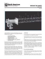
maior p 15 ab maior p 25 ab maior p 35 ab - System Control ...
maior p 15 ab maior p 25 ab maior p 35 ab - System Control ...
maior p 15 ab maior p 25 ab maior p 35 ab - System Control ...

You also want an ePaper? Increase the reach of your titles
YUMPU automatically turns print PDFs into web optimized ePapers that Google loves.
BRUCIATORI DI GASOLIOOIL BURNERSBRULEURS A MAZOUTQUEMADOR DE GASOLEOGASTECMAIOR P <strong>15</strong> ABMAIOR P <strong>25</strong> ABMAIOR P <strong>35</strong> ABSISTEMA IDRAULICOHYDRAULIC SYSTEMSYSTEME HYDRAULIQUESISTEMA HIDRAULICOLB49328.06.2002
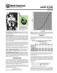
ALB493 Maior P <strong>15</strong>/<strong>25</strong>/<strong>35</strong> ABCARATTERISTICHE TECNICHEMODELLO MAIOR P <strong>15</strong> AB MAIOR P <strong>25</strong> AB MAIOR P <strong>35</strong> ABPortata termica max. kcal/h <strong>15</strong>0.000 <strong>25</strong>0.000 <strong>35</strong>0.000kW 178 296 4<strong>15</strong>Portata termica min. kcal/h 90.000 120.000 200.000kW 107 142 237Max. portata gasolio kg/h <strong>15</strong> <strong>25</strong> <strong>35</strong>Min. portata gasolio kg/h 9 12 20Tensione alimentazione 50 Hz V 230 230 230/400Potenza motore W 200 <strong>25</strong>0 370Giri -minuto Nº 2.800 2.800 2.800Trasf. accensione kV/mA 10/20 10/20 10/20App. controllo fiamma LANDIS LOA 24 LOA 24 LOA 24Combustibile : gasolio kcal/kg 10.200 max. visc 1,5°E a 20°CCURVE DI LAVOROPRESSIONE IN CAMERA DI COMBUSTIONEmbar 6543MAIOR P <strong>15</strong> ABMAIOR P <strong>25</strong> ABMAIOR P <strong>35</strong> AB21075 100 1<strong>25</strong> <strong>15</strong>0 175 200 2<strong>25</strong> <strong>25</strong>0 275100 <strong>15</strong>0 200 <strong>25</strong>0 30010 <strong>15</strong> 20 <strong>25</strong>PORTATA300 3<strong>25</strong> <strong>35</strong>0kcal/hx 1000<strong>35</strong>0 400 kW30kg/hDIMENSIONI DI INGOMBROAC BAC BD-D1ELHIGFMMP <strong>15</strong>/<strong>25</strong> ABP <strong>35</strong> ABMODELLO A B C D D1 E F G H I L MMAIOR P <strong>15</strong> AB 340 165 175 170 270 295 110 270 185 - - M8MAIOR P <strong>25</strong> AB 340 165 175 170 270 295 130 270 185 - - M8MAIOR P <strong>35</strong> AB 370 126 245 230 390 385 160 270 - 190 190 M8D = testa corta D1 = testa lungapag.2
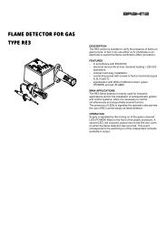
LB493 Maior P <strong>15</strong>/<strong>25</strong>/<strong>35</strong> ABACIRCUITO IDRAULICOMAIOR P <strong>25</strong>-<strong>35</strong> ABV1MAIOR P <strong>15</strong> ABV1445V<strong>25</strong>V21 - FLESSIBILI2 - FILTRO3 - RUBINETTO4 - ASPIRAZIONE5 - RITORNO112 3Bitubo dalla sommità del serbatoioALIMENTAZIONE COMBUSTIBILEBitubo in aspirazioneHH(m)0,511,522,533,5Lunghezza tubazioniø 8 mm30<strong>35</strong>4045505560ø 10 mm65707580859095HH(m)0,511,522,533,5Lunghezza tubazioniø 8 mm ø 10 mmLa lunghezza corretta delle tubazioni è data dalla somma di tutti i tratti rettilinei orizzontali, verticali e dellecurve. L’altezza statica di aspirazione è (max. 3.5m) data dalla distanza tra la valvola di fondo e l’asse dellapompa del bruciatore. La depressione non deve superare 0,45 bar; un valore maggiore potrebbe causare undeterioramento della pompa con conseguente aumento dei rumori meccanici ed eventuale rottura.23211917149455504540342822DATI DI TARATURAMAIOR P<strong>15</strong>ABMAIOR P <strong>25</strong> ABUGELLO POMPA PORTATA REGOLAZIONE TESTA REGOLAZIONE ARIAMANDATA ASPIRAZIONEGPH SPRY bar kg/h Pos. Pos. Pos.2.00 60° <strong>15</strong> 9,3 1 MIN MIN2.<strong>25</strong> 60° <strong>15</strong> 10,4 2 ÷ 32.50 60° <strong>15</strong> 11,6 3 ÷ 42.75 60° <strong>15</strong> 12,8 5 ÷ 63.00 60° 16 14,4 6 ÷ 7 MAX MAX2 x 1.50 60° 12 12,48 1 MIN MIN2 x 1.75 60° 12 14,58 2 ÷ 32 x 2.00 60° 12 16,66 4 ÷ 52 x 2.<strong>25</strong> 60° 12 18,74 5 ÷ 62 x 2.50 60° 12 20,82 6 ÷ 72 x 2.75 60° 12 24,4 7 MAX MAXMAIOR P <strong>35</strong> ABUGELLO : DANFOSS H÷S 80°÷60°; DELAVAN W 60°; STEINEN S 60°pag.3
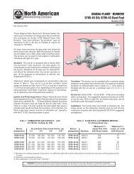
ALB493 Maior P <strong>15</strong>/<strong>25</strong>/<strong>35</strong> ABPULIZIA E SOSTITUZIONE DELL’UGELLOUtilizzare solo la apposita chiave fornita in dotazione pre rimuovere l’ugello, facendo attenzione a non danneggiaregli elettrodi. Montare il nuovo ugello con la medesima cura.N.B.: Verificare sempre la posizione degli elettrodi dopo il montaggio dell’ugello (vedi figura). Una posizioneerrata può comportare problemi di accensione.SUNTEC3,5 mm3,5 mm 3,5 mm6 mmMAIOR P <strong>35</strong> ABMAIOR P <strong>15</strong> ABMAIOR P <strong>25</strong> ABMAIOR P <strong>15</strong> AB : La pompa é del tipo a due regimi di pressione. Al collaudo é tarata a 10÷11 bar in bassafiamma e a <strong>15</strong>÷16 bar in alta fiamma.SUNTEC AT3 45AINNESCO E REGOLAZIONE DELLA POMPA GASOLIOSUNTEC AS 47 KSUNTEC AS 67 B4786346 5PV45VP36SUNTECSUNTECSUNTECSUNTEC32 11 - ASPIRAZIONE2 - RITORNO3 - SFIATO E PRESA MANOMETRO4 - PRESA VUOTOMETRO53 31<strong>25</strong> - REGOLAZIONE PRESSIONE ALTA FIAMMA6 - ALL' UGELLO7 - REGOLAZIONE PRESSIONE BASSA FIAMMA8 - PRESA DI PRESSIONE SPECIALESUNTEC3 32 1MAIOR P <strong>25</strong> AB : Nella pompa SUNTEC AS 47 K la pressione é regolata al collaudo a 12 bar.MAIOR P <strong>35</strong> : Nella pompa SUNTEC AS 67 B la pressione é regolata al collaudo a 12 bar.CONTROLLARE:- Che le tubazioni siano perfettamente a tenuta;- Che siano usati tubi rigidi (preferibilmente di rame), ove possibile;- Che la depressione in aspirazione non ecceda 0,45 bar, per evitare che la pompa entri in cavitazione;- Che la valvola di fondo sia dimensionata correttamente;La pressione della pompa viene regolata al valore di 12 bar durante il collaudo del bruciatore.Prima di avviare il bruciatore, spurgare l’aria contenuta nella pompa attraverso la presa del manometro.Riempire le tubazioni di gasolio per facilitare l’innesco della pompa.SUNTECAvviare il bruciatore e verificare la pressione di alimentazione della pompa. Se l’innesco della pompa nondovesse avvenire durante il primo prelavaggio, con conseguente, successiva entrata in blocco del bruciatore,riarmarne il blocco per riavviarlo, premendo il pulsante rosso sull’apparecchiatura di controllo.Se, ad innesco della pompa avvenuto, il bruciatore dovesse andare in blocco dopo la fase di prelavaggio, acausa di una caduta di pressione del gasolio nella pompa, riarmarne il blocco per riavviarlo. Non permetterepag.4
+-LB493 Maior P <strong>15</strong>/<strong>25</strong>/<strong>35</strong> ABAche la pompa funzioni per più di tre minuti senza gasolio.Nota: prima di avviare il bruciatore, assicurarsi che il tubo di ritorno sia aperto. Una sua eventuale occlusioneprovocherebbe una rottura dell’organo di tenuta della pompa.AVVIAMENTO E REGOLAZIONE DEL BRUCIATOREDopo aver eseguito l’installazione del bruciatore, verificare i seguenti punti:- Tensione di alimentazione del bruciatore ed i fusibili di protezione di rete.- I collegamenti del motore.- La corretta lunghezza delle tubazioni e la loro tenuta.- Il tipo di combustibile, che deve essere adatto al bruciatore.- Il collegamento dei termostati caldaia e delle varie sicurezze.- Il senso di rotazione del motore.- La corretta taratura della protezione termica del motore.Quando tutte queste condizioni sono verificate e soddisfatte, si può procedere con il collaudo del bruciatore.Dare tensione al bruciatore. L’apparecchiatura di controllo alimenterà, allo stesso tempo, sia il trasformatoredi accensione che il motore del bruciatore, che provvederà ad effettuare un prelavaggio della camera di combustioneper un periodo di 20 secondi circa.Al termine del prelavaggio, l’apparecchiatura di controllo apre le elettrovalvole della pompa gasolio e quelladel 1° stadio (Bassa fiamma), il trasformatore d’accensione produce una scintilla ed il bruciatore si accende.Dopo l’intervallo di sicurezza di 5 secondi, ad accensione avvenuta, l’apparecchiatura di controllo disinserisceil trasformatore di accensione quindi, dopo altri 10 secondi, aziona la serranda dell’aria alla massima aperturaed apre l’elettrovalvola del 2° stadio (Alta fiamma).In caso di accensione difettosa, l’apparecchiatura di controllo causa il blocco del bruciatore entro 5 secondi.In questo caso, il riarmo manuale del bruciatore non potrà avvenire prima che siano trascorsi 30 secondidall’entrata in blocco. Per avere una combustione ottimale, occorrerà regolare la portata dell’aria in ALTA eBASSA fiamma. La pressione di alimentazione della pompa gasolio dovrà aggirarsi sui 12 bar.REGOLAZIONE ARIA IN MANDATAMAIOR P <strong>15</strong> ABREGOLAZIONE TESTA DI COMBUSTIONE++MAIOR P <strong>25</strong> AB—AREGOLAZIONE TESTA DI COMBUSTIONEPer eseguire la regolazione della testa di combustione,procedere come segue:- allentare la vite A.- spostare la leva nella direzione delle frecce.- fissare la vite A.+MINMAXpag.5
ALB493 Maior P <strong>15</strong>/<strong>25</strong>/<strong>35</strong> ABREGOLAZIONE DELLA PORTATA DELL’ARIA DI COMBUSTIONE (ALTA-BASSA FIAMMA)Regolazione della portata d'aria in prima fiamma (bassafiamma):1- Avviare il bruciatore (controllando che la serranda aria siaparzialmente aperta).2 - Allentare il grano di fissaggio D.2 3 - Ruotare la serranda aria C sino ad ottenere una corretta+ –combustione.4 - Fissare il grano di fissaggio D.1Regolazione della portata d'aria in seconda fiamma (altafiamma):ATTENZIONE : data la presenza di olio in pressione all'internodel martinetto idraulico con il bruciatore funzionante inseconda fiamma (alta fiamma), la portata dovrà essere regolataDtramite la vite di regolazione 1 con il bruciatore funzionante inCprima fiamma (bassa fiamma). Il controllo della combustioneviene fatto una volta passati in seconda fiamma (alta fiamma).1 - Allentare la ghiera di fissaggio 2.2 - Aumentare o diminuire la portata agendo sulla vite di regolazione 1(in senso orario aumenta, antiorariodiminuisce).3 - Fissare la ghiera 2.4 - Passare manualmente dalla prima fiamma alla seconda fiamma e controllare i valori di combustione.COLLEGAMENTI ELETTRICITutti i bruciatori vengono collaudati a 400V - 50Hz trifase per i motori, e 230V - 50Hz monofase con neutroper le apparecchiature ausiliarie. Se si rendesse necessario alimentare il bruciatore con 230V - 50Hz trifasesenza neutro, modificare i collegamenti sul motore e sulla morsettiera come indicato in figura. Proteggere lalinea di alimentazione del bruciatore con fusibili adeguati.pag.6
LB493 Maior P <strong>15</strong>/<strong>25</strong>/<strong>35</strong> ABBTECHNICAL DATAMODELS MAIOR P <strong>15</strong> AB MAIOR P <strong>25</strong> AB MAIOR P <strong>35</strong> ABThermal power max. kcal/h <strong>15</strong>0.000 <strong>25</strong>0.000 <strong>35</strong>0.000kW 178 296 4<strong>15</strong>Thermal power min. kcal/h 90.000 120.000 200.000kW 107 142 237Max. flow rate light oil kg/h <strong>15</strong> <strong>25</strong> <strong>35</strong>Min. flow rate light oil kg/h 9 12 20Feeding power 50 Hz V 230 230 230/400Motor W 200 <strong>25</strong>0 370Rpm Nº 2.800 2.800 2.800Ignition transformer kV/mA 10/20 10/20 10/20<strong>Control</strong> box LANDIS LOA 24 LOA 24 LOA 24Fuel : light oil kcal/kg 10.200 max. visc 1,5°E a 20°CWORKING FIELDSmbar 6PRESSURE IN THE COMBUSTION CHAMBER543MAIOR P <strong>15</strong> ABMAIOR P <strong>25</strong> ABMAIOR P <strong>35</strong> AB21075 100 1<strong>25</strong> <strong>15</strong>0 175 200 2<strong>25</strong> <strong>25</strong>0 275100 <strong>15</strong>0 200 <strong>25</strong>0 30010 <strong>15</strong> 20 <strong>25</strong>BURNER OUTPUT300 3<strong>25</strong> <strong>35</strong>0kcal/hx 1000<strong>35</strong>0 400 kW30kg/hOVERALL DIMENSIONSAC BAC BD-D1ELHGIFMMP <strong>15</strong>/<strong>25</strong> ABP <strong>35</strong> ABMODELS A B C D D1 E F G H I L MMAIOR P <strong>15</strong> AB 340 165 175 170 270 295 110 270 185 - - M8MAIOR P <strong>25</strong> AB 340 165 175 170 270 295 130 270 185 - - M8MAIOR P <strong>35</strong> AB 370 126 245 230 390 385 160 270 - 190 190 M8D = short head D1 = long headpag.7
BLB493 Maior P <strong>15</strong>/<strong>25</strong>/<strong>35</strong> ABHYDRAULIC CIRCUITMAIOR P <strong>25</strong>-<strong>35</strong> ABV1MAIOR P <strong>15</strong> ABV1445V<strong>25</strong>V21 - HOSE2 - OIL FILTER3 - OIL COCK4 - SUCTION5 - RETURN112 3MAXIMUM LENGTH OF SUCTION LINES FOR TWO-PIPE SYSTEMTwo-pipe siphon feed systemTwo-pipe lift systemHH(m)0,511,522,533,5Pipe lengthø 8 mm30<strong>35</strong>4045505560ø 10 mm65707580859095HH(m)0,511,522,533,5Pipe lengthø 8 mm232119171494ø 10 mmTo correct length of pipes is calculated by summing up the length of all vertical and horizontal right sectionsand bends. The static suction head will be the distance between the non-return valve and theburner’s pump axle. The depression must not be greater than 0.45 bar; should it be higher, some damagescould occur to the pump, with consequent increase in mechanical noises and ,eventually, a failure.55504540342822ADJUSTMENT DATAMAIOR P<strong>15</strong>ABMAIOR P <strong>25</strong> ABNOZZLE PUMP OUTPUT FIRING HEAD SETTING AIR DAMPER ADJUSTMENTPRESSURE SIDE SUCTIONGPH SPRY bar kg/h Pos. Pos. Pos.2.00 60° <strong>15</strong> 9,3 1 MIN MIN2.<strong>25</strong> 60° <strong>15</strong> 10,4 2 ÷ 32.50 60° <strong>15</strong> 11,6 3 ÷ 42.75 60° <strong>15</strong> 12,8 5 ÷ 63.00 60° 16 14,4 6 ÷ 7 MAX MAX2 x 1.50 60° 12 12,48 1 MIN MIN2 x 1.75 60° 12 14,58 2 ÷ 32 x 2.00 60° 12 16,66 4 ÷ 52 x 2.<strong>25</strong> 60° 12 18,74 5 ÷ 62 x 2.50 60° 12 20,82 6 ÷ 72 x 2.75 60° 12 24,4 7 MAX MAXMAIOR P <strong>35</strong> ABNOZZLE : DANFOSS H÷S 80°÷60°; DELAVAN W 60°; STEINEN S 60°pag.8
LB493 Maior P <strong>15</strong>/<strong>25</strong>/<strong>35</strong> ABNOZZLE CLEANING AND REPLACEMENTUse only the suit<strong>ab</strong>le box wrench provided for this operation to remove the nozzle, taking care to not damagethe electrodes. Fit the new nozzle with the same care.Note: Always check the position of electrodes after having replaced the nozzle (see illustration). A wrong positioncould cause ignition troubles.BSUNTEC3,5 mm3,5 mm 3,5 mm6 mmMAIOR P <strong>35</strong> ABMAIOR P <strong>15</strong> ABMAIOR P <strong>25</strong> ABMAIOR P <strong>15</strong> AB : The pump is a two pressure level type. During the test phase, it is adjusted to 10÷11 barfor low flame, and <strong>15</strong>÷16 bar for high flame.SUNTEC AT3 45APRIMING AND ADJUSTMENT OF OIL PUMPSUNTEC AS 47 KSUNTEC AS 67 B4786346 5PV45VP36SUNTECSUNTECSUNTECSUNTEC32 11 - INLET2 - RETURN3 - BLEED AND PRESSURE GAUGE PORT4 - VACUUM GAUGE PORT53 31<strong>25</strong> - PRESSURE ADJUSTMENT6 - TO NOZZLE7 - PRESSURE ADJUSTMENT8 - SPECIAL PRESSURE PORTSUNTEC3 32 1MAIOR P <strong>25</strong> AB : The pressure of SUNTEC AS 47 K pump is adjusted to 12 bar during the test phase.MAIOR P <strong>35</strong> : The pressure of SUNTEC AS 67 B pump is adjusted to 12 bar during the test phase.VERIFY:- That piping system is perfectly sealed;- That the use of hoses is avoided whenever is possible (use copper pipes prefer<strong>ab</strong>ly);- That depression is not greater than 0,45 bar, to avoid pump’s cavitation;- That check valve is suit<strong>ab</strong>ly designed for the duty;The pump pressure is set at a value of 12 bar during the testing of burners.Before starting the burner, bleed the air in the pump through the gauge port.Fill the piping with light-oil to facilitate the pump priming.SUNTECStart the burner and check the pump feeding pressure. In case the pump priming does not take place duringthe first prepurging, with a consequent, subsequent lock-out of the burner, rearm the burner’s lock-out torestart, by pushing the button on the control box. If, after a successful pump priming, the burner locks-outafter the prepurging, due to a fuel pressure drop in the pump, rearm the burner’s lock-out to restart the bur-pag.9
+—-BLB493 Maior P <strong>15</strong>/<strong>25</strong>/<strong>35</strong> ABner. Do never allow the pump working without oil for more than three minutes.Note: before starting the burner, check that the return pipe is open. An eventual obstruction could damagethe pump sealing device.BURNER START-UP AND ADJUSTMENTOnce having installed the burner, check the following items:- The burner power feeding and the main line protection fuses- The correct length of pipes and that the same are sealed.- The type of fuel, which must be suit<strong>ab</strong>le for burner.- The connection of boiler’s thermostats and all the safeties.- The motor rotation direction.- The correct calibration of the motor’s thermal protection.When all the <strong>ab</strong>ove mentioned conditions are checked and accomplished, it is possible to go on with burner’stests. Power the burner. The control box feeds the ignition transformer and the burner’s motor at the sametime, which will run a prepurging of the combustion chamber for <strong>ab</strong>out 20 sec.At the end of prepurging, the control box opens the fuel pump and the 1st stage (Low flame) solenoid valves,the ignition transformer produces a spark and the burner ignites. After a safety interval of 5 seconds and acorrect ignition, the control box turns off the ignition transformer and, 10 seconds later, sets the air damperto its maximum opening and opens the 2nd stage solenoid valve (High flame). In case of faulty ignition, thecontrol box switches the burner into safety condition. In such a case, the manual rearming of the burner shallnot take place before 30 seconds have elapsed from the burner’s safety shutdown. In order to obtain an optimalcombustion, it is necessary adjust the LOW - HIGH flame air flow. The fuel pump feeding pressure,must remain around 12 bar.AIR REGULATION PRESSURE SIDEMAIOR P <strong>15</strong> ABFIRING HEAD SETTING++MAIOR P <strong>25</strong> ABAFIRING HEAD SETTINGTo adjust the firing head, proceed as follows:- Loosen the locking screw A.- Move the lever toward the arrows.- Tighten the locking screw.+MINMAXpag.10
LB493 Maior P <strong>15</strong>/<strong>25</strong>/<strong>35</strong> AB BCOMBUSTION AIR FLOW ADJUSTMENT (HIGH-LOW FLAME)Air flow rate adjustment in Low flame running:1) - Start the burner (checking that the air damper is partiallyopen).2) - Loosen clamping screw D.3) - Turn air damper C until obtaining a correct combustion2 + –(checked with a combustion gas analysis set).4) - Tighten clamping screw D.1Air flow rate adjustment in High flame running:WARNING: due to the presence of oil under pressure in thehydraulic jack when the burner is working in High flame condition,the air flow rate adjustment is to be made with the useof an adjusting ring nut 1 with the burner running in Lowflame condition. The combustion checks are to be done onceDthe burner is turned to High flame condition again.C1) - Loosen clamping ring nut 22) - Increase or decrease the air flow rate through the adjustingring nut 1 (Clockwise to increase, counterclockwise to decrease).3) - Tighten clamping ring nut 2.4) - Switch manually from Low flame to High flame and check the combustion values.ELECTRICAL CONNECTIONSAll burners are factory tested at 400V - 50Hz 3-phase for motors, and 230V - 50Hz single phase with neutralfor auxiliary equipments. Should it be necessary to power the burner with 230V - 50Hz, modify the connectionson motor and the terminal board as shown in the picture. Protect the burner supply line with suit<strong>ab</strong>lefuses and/or other safety devices as required by the local regulations on the matter.pag.11
CLB493 Maior P <strong>15</strong>/<strong>25</strong>/<strong>35</strong> ABCARACTERISTIQUES TECHNIQUESMODELES MAIOR P <strong>15</strong> AB MAIOR P <strong>25</strong> AB MAIOR P <strong>35</strong> ABPuissance thérmique max. kcal/h <strong>15</strong>0.000 <strong>25</strong>0.000 <strong>35</strong>0.000kW 178 296 4<strong>15</strong>Puissance thérmique min. kcal/h 90.000 120.000 200.000kW 107 142 237Débit max. kg/h <strong>15</strong> <strong>25</strong> <strong>35</strong>Débit min kg/h 9 12 20Tension d'alimentation 50 Hz V 230 230 230/400Moteur W 200 <strong>25</strong>0 370Tours par minute Nº 2.800 2.800 2.800Transformateur kV/mA 10/20 10/20 10/20Coffret de sécurité LANDIS LOA 24 LOA 24 LOA 24Combustible : mazout kcal/kg 10.200 max. visc 1,5°E a 20°CCOURBE DE TRAVAILmbar 6PRESSION DANS LA CHAMBRE DE COMBUSTION543MAIOR P <strong>15</strong> ABMAIOR P <strong>25</strong> ABMAIOR P <strong>35</strong> AB21075 100 1<strong>25</strong> <strong>15</strong>0 175 200 2<strong>25</strong> <strong>25</strong>0 275100 <strong>15</strong>0 200 <strong>25</strong>0 300300 3<strong>25</strong> <strong>35</strong>0kcal/hx 1000<strong>35</strong>0 400 kW10 <strong>15</strong> 20 <strong>25</strong>DEBIT30kg/hDIMENSIONS D'ENCOMBREMENTAC BAC BD-D1ELHGIFMMP <strong>15</strong>/<strong>25</strong> ABP <strong>35</strong> ABMODELES A B C D D1 E F G H I L MMAIOR P <strong>15</strong> AB 340 165 175 170 270 295 110 270 185 - - M8MAIOR P <strong>25</strong> AB 340 165 175 170 270 295 130 270 185 - - M8MAIOR P <strong>35</strong> AB 370 126 245 230 390 385 160 270 - 190 190 M8D = tete courte D1 = tete longuepag.12
LB493 Maior P <strong>15</strong>/<strong>25</strong>/<strong>35</strong> ABCCIRCUIT HYDRAULIQUEMAIOR P <strong>25</strong>-<strong>35</strong> ABV1MAIOR P <strong>15</strong> ABV1445V<strong>25</strong>V21 - FLEXIBLES2 - FILTRE3 - ROBINET D'ARRET4 - ASPIRATION5 - RETOUR112 3RACCORDEMENT DU CIRCUIT D'ALIMENTATION FODRaccordement bitube en chargeRaccordement bitube en aspirationHH(m)0,511,522,533,5Longueur tuyaux en mètresø 8 mm30<strong>35</strong>4045505560ø 10 mm65707580859095HH(m)0,511,522,533,5Longueur tuyaux en mètresø 8 mm ø 10 mmLa longueur correcte de la canalisation est donnée par la somme de la longueur de toutes les sections rectiligneshorizontales et verticales, ainsi que les coudes. La hauteur statique d’aspiration (max. 3.5m) est donnéepar la distance entre la vanne de non retour et l’axe pompe du brûleur. La dépression en aspiration ne devrapas dépasser les 0.45 bar; en cas de dépression plus importante, la pompe pourrait s’endommager avec uneconséquente augmentation des bruits mécaniques et, a la limite, une panne totale.23211917149455504540342822DONNEES DE REGLAGEMAIOR P<strong>15</strong>ABMAIOR P <strong>25</strong> ABGICLEUR POMPE DEBIT REGLAGE TETE REGLAGE VOLET D’AIREN ENTREE EN SORTIEGPH SPRY bar kg/h Pos. Pos. Pos.2.00 60° <strong>15</strong> 9,3 1 MIN MIN2.<strong>25</strong> 60° <strong>15</strong> 10,4 2 ÷ 32.50 60° <strong>15</strong> 11,6 3 ÷ 42.75 60° <strong>15</strong> 12,8 5 ÷ 63.00 60° 16 14,4 6 ÷ 7 MAX MAX2 x 1.50 60° 12 12,48 1 MIN MIN2 x 1.75 60° 12 14,58 2 ÷ 32 x 2.00 60° 12 16,66 4 ÷ 52 x 2.<strong>25</strong> 60° 12 18,74 5 ÷ 62 x 2.50 60° 12 20,82 6 ÷ 72 x 2.75 60° 12 24,4 7 MAX MAXMAIOR P <strong>35</strong> ABGICLEUR : DANFOSS H÷S 80°÷60°; DELAVAN W 60°; STEINEN S 60°pag.13
CLB493 Maior P <strong>15</strong>/<strong>25</strong>/<strong>35</strong> ABNETTOYAGE ET REMPLACEMENT DU GICLEURUtiliser seulement la clé en dotation, prévue pour cette opération, pour dévisser le gicleur, en veillant à ne pasendommager les électrodes. Monter le nouveau gicleur par le même soin.Note: Après le remplacement du gicleur, vérifier toujours la position des électrodes (voir à l’illustration). Uneposition erronée des électrodes pourrait donner des problèmes d’allumage.SUNTEC3,5 mm3,5 mm 3,5 mm6 mmMAIOR P <strong>35</strong> ABMAIOR P <strong>15</strong> ABMAIOR P <strong>25</strong> ABMAIOR P <strong>15</strong> AB : La pompe est du type à deux niveaux de pression.Pendant la phase des essais, elle est réglée à 10÷11 bar en 1re allure, et <strong>15</strong>÷16 bar en 2me allure.SUNTEC AT3 45AAMORCAGE ET REGULATION DE LA POMPE FIOULSUNTEC AS 47 KSUNTEC AS 67 B4786346 5PV45VP36SUNTECSUNTECSUNTECSUNTEC32 11 - ASPIRATION2 - RETOUR3 - RACCORDEMENT DUMANOMETRE ET PURGE53 312SUNTEC3 32 14 - RACCORDEMENT DU VACUOMETRE5 - VIS DE REGLAGE DE LA PRESSION REGULACIÓN DE PRESIÓN6 - AU GICLEUR7 - VIS DE REGLAGE DE LA PRESSION REGULACIÓN DE PRESIÓN8 - PRISE DE PRESSION SPECIALEMAIOR P <strong>25</strong> AB : La pression de la pompe SUNTEC AS 47 K est réglée à 12 bar pendant la phase des essais.MAIOR P <strong>35</strong> AB : La pression de la pompe SUNTEC AS 67 B est réglée à 12 bar pendant la phase des essais.VERIFIER:- Que les canalisations soient parfaitement étanches;- Qu’on évite l’emploi de tuyaux flexibles, lorsque possible (utiliser, préfér<strong>ab</strong>lement, tuyaux en cuivre).- Que la dépression ne dépasse pas 0,45 bar, pour éviter la cavitation de la pompe.- Que la vanne de non retour soit appropriéeLa pression de la pompe est réglée à 12 bar pendant les essais à l’usine.Avant de démarrer le brûleur, purger l’air contenue dans la pompe à travers la prise du manomètre.SUNTECRemplir la tuyauterie de fioul pour faciliter l’amorçage de la pompe.Démarrer le brûleur et verifier la pression d’alimentation de la pompe.S’il dût se passer que l’amorçage de la pompe ne se verifie pas pendant le premier prebalayage, avec une consequente,successive mise en sécurité du brûleur, rearmer la mise en sécurité du brûleur pour le démarrer à nouveau,en appuyant sur le bouton du coffret de sécurité.Si, après un amorçage effectué normalement, le brûleur se met en sécurité par faute d’une chute de pressionpag.14
+-LB493 Maior P <strong>15</strong>/<strong>25</strong>/<strong>35</strong> ABCdu fioul dans la pompe, rearmer la mise en sécurité pour le rédémarrer.Ne jamais laisser que la pompe tourne sans fioul pendant plus que trois minutes. Dans le cas où l’amorçage dela pompe ne s’effectue pas pendant le premier prebalayage, déclencher la mise en sécurité du brûleur.Note: avant de démarrer le brûleur, s’assurer que le tuyau de retour soit ouvert. Une obstruction éventuellepourrait causer la rupture du dispositif d’étanchéité de la pompe.MISE EN SERVICE ET REGLAGE DU BRULEURAprès avoir effectué l’installation du brûleur, vérifier les points suivants:- Tension d’alimentation du brûleur et les fusibles de protection de ligne.- Les connexions du moteur.- La longueur correcte de la tuyauterie et que la même soit étanche.- Le type de combustible, qui doit être indiqué pour le brûleur.- La connexion des thermostats chaudière et des sécurités.- Le sens de rotation du moteur.- La calibration correcte de la protection termique du moteur.Une fois que toutes ces conditions ont été verifiées, on pourra proceder aux essais du brûleur.Alimenter le brûleur. Le coffret de sécurité alimente, en même temps, le transformateur d’allumage et lemoteur du brûleur, qui pourvoit à effectuer un prebalayage de la chambre de combustion pendant environs20 secondes.A la fin du prebalayage, le coffret de sécurité ouvre l’électrovanne de la pompe fioul et de 1re Allure (Petiteallure), le transformateur produit un’étincelle et le brûleur s’allume.Après un intervalle de sécurité de 5 secondes et un allumage correct, le coffret de sécurité débranche le transformateurd’allumage et, après d’autres 10 secondes, porte le clapet d’air à son ouverture maximale et ouvrel’électrovanne de 2me Allure (Grande allure).En cas de faute d’allumage, le coffret de sécurité met le brûleur en sécurité dans les 5 secondes. Dans ce cas, leréarmement manuel ne pourra intervenir qu’après 30 secondes env. de la mise en sécurité du brûleur.Pour obtenir une combustion optimale, il faudra réguler la portée de l’air en 1re et 2me ALLURE. La pressiond’alimentation de la pompe fioul devra toujours se garder autour de 12 bar.REGLAGE DE L'AIR EN ENTREEMAIOR P <strong>15</strong> ABREGLAGE DE LA TETE DE COMBUSTION++MAIOR P <strong>25</strong> AB—AREGLAGE DE LA TETE DE COMBUSTIONPour régler la tête de combustion, proceder de cettemanière:- Dévisser la vis de blocage A.- Déplacer le levier en direction des flèches.- Visser à nouveau la vis de blocage.+MINMAXpag.<strong>15</strong>
CLB493 Maior P <strong>15</strong>/<strong>25</strong>/<strong>35</strong> ABREGLAGE DE LA PORTEE DE L’AIR COMBURANTE (1RE / 2ME ALLURE)2 + –Réglage de la portée de l’air en 1re Allure (Petite allure).1) - Faire démarrer le brûleur (en vérifiant que le clapet de l’airsoit partiellement ouvert).2) - Desserrer la vis de fixation D.3) - Tourner le clapet de l’air C jusqu’à obtenir une combustioncorrecte (par une analyse des fumées).4) - Serrer la vis de fixation D.1Réglage de la portée de l’air en 2me Allure (Grande allure).ATTENTION: suite à la présence de huile sous pression dansle vérin hydraulique avec le brûleur fonctionnant en 2me allure,la portée de l’air devra être réglée par la vis de réglage 1 avecle brûleur en 1re allure (petite allure). Le contrôle de la combustionse fera une fois passé à la 2me allure (grande allure).1) - Desserrer la bague de fixation 2.D2) - Augmenter ou réduire la portée à l’aide de la bague deCréglage 1 ( tourner vers droite pour l’augmenter et vers gauchepour la réduire).3) - Serrer la bague de fixation 2.4) - Passer manuellement en 2me Allure (grande allure) et vérifier les valeurs de combustion.BRANCHEMENT ELECTRIQUETous les bruleurs sont essayés à l’usine à 400V - 50Hz triphasé pour les moteurs, et 230V - 50Hz monophaséavec neutre pour les equipments auxiliaires. Dans le cas où il fût nécessaire alimenter le brûleur en 230V -50Hz triphasé sans neutre, modifier les connexions sur le moteur et sur la boîte à bornes suivant la figure.Protéger la ligne d’alimentation du brûleur par des fusibles appropriés et/ou les autres dispositifs de sécuritésuivant les dispositions locales en matière.pag.16
LB493 Maior P <strong>15</strong>/<strong>25</strong>/<strong>35</strong> ABDCARACTERISTICAS TECNICASMODELOS MAIOR P <strong>15</strong> AB MAIOR P <strong>25</strong> AB MAIOR P <strong>35</strong> ABPotencia térmica máx. kcal/h <strong>15</strong>0.000 <strong>25</strong>0.000 <strong>35</strong>0.000kW 178 296 4<strong>15</strong>Potencia térmica min. kcal/h 90.000 120.000 200.000kW 107 142 237Caudal máx. de gasóleo kg/h <strong>15</strong> <strong>25</strong> <strong>35</strong>Caudal mín. de gasóleo kg/h 9 12 20Aliment.eléct. 50 Hz V 230 230 230/400Potencia del motor W 200 <strong>25</strong>0 370Revol. por minuto Nº 2.800 2.800 2.800Transformador de encendido kV/mA 10/20 10/20 10/20Equipo de control de la llama LANDIS LOA 24 LOA 24 LOA 24Combustible : gasóleo kcal/kg 10.200 max. visc 1,5°E a 20°CCURVAS DE TRABAJOPRESION EN LA CAMARA DE COMBUSTIONmbar 6543MAIOR P <strong>15</strong> ABMAIOR P <strong>25</strong> ABMAIOR P <strong>35</strong> AB21075 100 1<strong>25</strong> <strong>15</strong>0 175 200 2<strong>25</strong> <strong>25</strong>0 275100 <strong>15</strong>0 200 <strong>25</strong>0 30010 <strong>15</strong> 20 <strong>25</strong>CAUDAL DEL QUEMADOR300 3<strong>25</strong> <strong>35</strong>0kcal/hx 1000<strong>35</strong>0 400 kW30kg/hDIMENSIONES GLOBALESAC BAC BD-D1ELHGIFMMP <strong>15</strong>/<strong>25</strong> ABP <strong>35</strong> ABMODELOS A B C D D1 E F G H I L MMAIOR P <strong>15</strong> AB 340 165 175 170 270 295 110 270 185 - - M8MAIOR P <strong>25</strong> AB 340 165 175 170 270 295 130 270 185 - - M8MAIOR P <strong>35</strong> AB 370 126 245 230 390 385 160 270 - 190 190 M8D = c<strong>ab</strong>eza corta D1 = c<strong>ab</strong>eza largapag.17
DLB493 Maior P <strong>15</strong>/<strong>25</strong>/<strong>35</strong> ABSISTEMA HIDRÁULICOMAIOR P <strong>25</strong>-<strong>35</strong> ABV1MAIOR P <strong>15</strong> ABV1445V<strong>25</strong>V21 - LATIGUILLOS2 - FILTRO3 - VÁLVULA DE4 - ASPIRACIÓN5 - RETORNO112 3ALIMENTACION DEL COMBUSTIBLETubo doble de la parte superior del depósitoTubo doble de aspiraciónHH(m)0,511,522,533,5Longitud de los tubosø 8 mm30<strong>35</strong>4045505560ø 10 mm65707580859095HH(m)0,511,522,533,5Longitud de los tubosø 8 mm ø 10 mmLa longitud de la tubería se obtiene de la suma de todas las secciones rectilíneas horizontales y verticales y delas curvas. La altura estática de aspiración (máx. 3.5m) es la distancia entre la válvula anti retorno y el ejebomba del quemador. La depresión no debe superar los 0.45 bar; una depresión mas grande podría perjudicarel funcionamiento de la bomba, con consecuente aumento del ruido mecánico y , al final, una ruptura.23211917149455504540342822DATOS DE REGULACIÓNMAIOR P<strong>15</strong>ABMAIOR P <strong>25</strong> ABINYECTOR BOMBA CAUDAL REGLAJE DE LA CABEZA REGLAJE DEL AIREIMPULSIÓN ASPIRACIÓNGPH SPRY bar kg/h Pos. Pos. Pos.2.00 60° <strong>15</strong> 9,3 1 MIN MIN2.<strong>25</strong> 60° <strong>15</strong> 10,4 2 ÷ 32.50 60° <strong>15</strong> 11,6 3 ÷ 42.75 60° <strong>15</strong> 12,8 5 ÷ 63.00 60° 16 14,4 6 ÷ 7 MAX MAX2 x 1.50 60° 12 12,48 1 MIN MIN2 x 1.75 60° 12 14,58 2 ÷ 32 x 2.00 60° 12 16,66 4 ÷ 52 x 2.<strong>25</strong> 60° 12 18,74 5 ÷ 62 x 2.50 60° 12 20,82 6 ÷ 72 x 2.75 60° 12 24,4 7 MAX MAXMAIOR P <strong>35</strong> ABINYECTOR : DANFOSS H÷S 80°÷60°; DELAVAN W 60°; STEINEN S 60°pag.18
LB493 Maior P <strong>15</strong>/<strong>25</strong>/<strong>35</strong> ABLIMPIEZA Y SOSTITUCIÓN DEL INYECTORUtilizar solamente la llave de suministro para desmontar el inyector, teniendo cuidado de no estropear loselectrodos. Montar el nuevo inyector con el mismo cuidado.Nota: Comprobar todavía la posición de los electrodos después del montaje (ver a la ilustración). Una posiciónerrada puede originar problemas de encendido.SUNTEC3,5 mmD3,5 mm 3,5 mm6 mmMAIOR P <strong>35</strong> ABMAIOR P <strong>15</strong> ABMAIOR P <strong>25</strong> ABCEBADO Y REGULACION DE LA BOMBA GASOLEOMAIOR P <strong>15</strong> AB : La bomba es del tipo con dos regímenes de presión.Durante la prueba final es calibrada a 10÷11 bar en llama baja y a <strong>15</strong>÷16 bar en llama alta.SUNTEC AT3 45ASUNTEC AS 47 KSUNTEC AS 67 B4786346 5PV45VP36SUNTECSUNTECSUNTECSUNTEC32 11 - ASPIRACIÓN2 - RETORNO3 - PURGA Y TOMA PARA EL MANÓMETRO4 - TOMA PARA EL VACUÓMETRO53 312SUNTEC3 32 <strong>15</strong> - REGULACIÓN DE PRESIÓN6 - AL INYECTOR7 - REGULACIÓN DE PRESIÓN8 - TOMA ESPECIAL.MAIOR P <strong>25</strong> AB : En la bomba SUNTEC AS 47 K, la presión se regula durante la prueba final a 12 bar.MAIOR P <strong>35</strong> : En la bomba SUNTEC AS 67 B, la presión se regula durante la prueba final a 12 bar.COMPROBAR:- Que las tuberías sean totalmente estancas;- Que non se utilicen tubos flexibles, donde posible (utilizar, preferiblemente, tubos de cobre);- Que la depresión no sea superior a los 0,45 bar, para evitar que la bomba entre en cavitación;- Que la válvula de non retorno sea adecuada;La presión de la bomba es regulada a 12 bar por el f<strong>ab</strong>ricante, durante los ensayos.Antes de arrancar el quemador, purgar el aire contenido en la bomba a través la toma para el manómetro.Llenar las tuberías con gasóleo, para facilitar el cebado de la bomba. Arrancar el quemador y comprobar laSUNTECpresión de alimentación de la bomba. Si se verificases que el cebado de la bomba no se efectúa durante el primerprebarrido, con consecuente, sucesivo bloqueo del quemador, rearmar el bloqueo para arrancarlo nuevamente,presionando el botón del equipo de control. Si, una vez que el cebado se ha efectuado normalmente,el quemador se bloquease después del prebarrido, por falta de presión del gasóleo en la bomba, armar el bloqueopara arrancarlo nuevamente.Nunca permitir que la bomba funcione sin gasóleo durante más de tres minutos. Nota: antes de poner enpag.19
+-DLB493 Maior P <strong>15</strong>/<strong>25</strong>/<strong>35</strong> ABmarcha el quemador, comprobar que el tubo de retorno esté <strong>ab</strong>ierto. Una oclusión eventual, podría estropearel elemento de estanqueidad de la bomba. del prebarrido, por falta de presión del gasóleo en la bomba, armarel bloqueo para arrancarlo nuevamente.Nunca permitir que la bomba funcione sin gasóleo durante más de tres minutos.Nota: antes de poner en marcha el quemador, comprobar que el tubo de retorno esté <strong>ab</strong>ierto. Una oclusióneventual, podría estropear el elemento de estanqueidad de la bomba.FUNCIONAMIENTO Y REGULACIÓN DEL QUEMADORDespués de h<strong>ab</strong>er instalado el quemador, comprobar los puntos siguientes:- La tensión de alimentación del quemador y los fusibles de protección de línea.- Las conexiones del motor.- La largueza correcta y la estanqueidad de la tubería.- El tipo de combustible, que debe ser adecuado para el quemador.- Las conexión de los termostatos de caldera y de los dispositivos de seguridad.- El sentido de rotación del motor.- La regulación correcta de la protección térmica del motor.Cuando todas estas condiciones se cumplen, es posible de proceder con las pruebas del quemador.Alimentar el quemador. El equipo de control alimenta, al mismo tiempo, el transformador de encendido y elmotor del quemador, que empieza el prebarrido de la cámara de combustión por unos 20 segundos.Al termino del prebarrido, el equipo de control <strong>ab</strong>re la electroválvula de la bomba de gasóleo y la electroválvulade 1a Llama (Baja llama), el transformador de encendido genera una chispa y el quemador se enciende.Después de un intervalo de seguridad de 5 segundos, y un encendido correcto, el equipo de control desconecteel transformador de encendido y, después otros 10 segundos manda el cierre del aire en posición de <strong>ab</strong>erturamáxima y <strong>ab</strong>re la electroválvula de 2a Llama (Alta llama).En caso de falta de encendido, el equipo de control pone el quemador en posición de seguridad dentro de los5 segundos. En este caso, el rearme manual del quemador no podrá ocurrir antes que se hayan pasado unos30 segundos de la misa en seguridad del quemador.Para obtener una combustión optimal, se necesitara regular el caudal del aire en 1a y 2a llama.La presión de alimentación de la bomba debe estar acerca de los 12 bar.REGLAJE DEL AIRE IMPULSIÓNREGLAJE DE LA CABEZA DE COMBUSTIÓNMAIOR P <strong>15</strong> AB++MAIOR P <strong>25</strong> AB—+AREGLAJE DE LA CABEZA DE COMBUSTIÓNPara regular la c<strong>ab</strong>eza de combustión, proceder en elsiguiente modo:- Aflojar el tornillo de bloqueo A.- Mover la palanca en dirección de las flechas.- Atornillar el tornillo de bloqueo.MINMAXpag.20
REGULACIÓN DEL CAUDAL DEL AIRE DE COMBUSTIÓNLB493 Maior P <strong>15</strong>/<strong>25</strong>/<strong>35</strong> AB2 + –Regulación del caudal del aire en 1a Llama (Baja llama):1) - Poner en marcha el quemador (comprobando que el cierredel aire esté parcialmente <strong>ab</strong>ierto).2) - Aflojar el tornillo de fijación D.3) - Girar el cierre del aire hasta obtener una combustión correcta(comprobando los gases de combustión).4) - Fijar el tornillo de fijación D.1Regulación del caudal del aire en 2a Llama (Alta llama):CUIDADO: debido a la presencia de aceite bajo presión en elcilindro hidráulico con el quemador funcionante en 2allama, el caudal del aire deberá ser regulado con el quemadorfuncionante en 1a llama. El control de la combustiónse hará una vez que se h<strong>ab</strong>rá pasado en 2a llama Altallama).D1) - Aflojar el anillo de fijación 2.C2) - Aumentar o reducir el caudal por medio del anillo deregulación 1 (a la derecha para aumentar y a la izquierdapara reducir).3) - Fijar el anillo de fijación 2.4) - Pasar manualmente en 2a Llama y comprobar los valores de combustiónDCONEXIONES ELECTRICASTodos los quemadores son ensayados por el f<strong>ab</strong>ricante a 400V - 50Hz trifásico para el motor, y 230V - 50Hzmonofásico con neutro para los equipos auxiliares. En caso que fuese necesario alimentar el quemador con230V - 50Hz trifásico sin neutro, modificar las conexiones del motor y en el t<strong>ab</strong>lero de bornes siguiendo lailustración. Proteger la línea de alimentación del quemador con fusibles adecuados y/o con todos los dispositivosde seguridad especificados por las normas locales en materia.pag.21
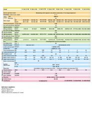
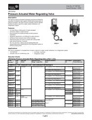
ABCDLB493 Maior P <strong>15</strong>/<strong>25</strong>/<strong>35</strong> AB23381 45687102692021484750491812241614363713<strong>15</strong>11MAIOR P <strong>15</strong> AB284527<strong>25</strong>2217343146293019<strong>35</strong>3233pag.22
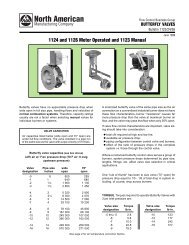
LB493 Maior P <strong>15</strong>/<strong>25</strong>/<strong>35</strong> ABABCD23381 456871026920214847504918391224164014363713<strong>15</strong>11MAIOR P <strong>25</strong> AB284527<strong>25</strong>22301734314629<strong>35</strong>193<strong>25</strong>133pag.23
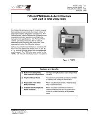
ABCDLB493 Maior P <strong>15</strong>/<strong>25</strong>/<strong>35</strong> AB38<strong>15</strong>673120212 3482493912234240411314<strong>25</strong><strong>15</strong>MAIOR P <strong>35</strong> AB43441145282234311746293019<strong>35</strong>3233pag.24
LB493 Maior P <strong>15</strong>/<strong>25</strong>/<strong>35</strong> ABAN° DESCRIZIONEMAIOR P <strong>15</strong> ABcodiceMAIOR P <strong>25</strong> AB MAIOR P <strong>35</strong> ABcodice codice1 - POMPA SUNTEC AT3 45 A P134/1 - -SUNTEC AS 47 K - P122 -SUNTEC AS 67 B - - P1122 - BOBINA SUNTEC V504 V504 V5043 - VALVOLA SUNTEC V410 V410 V4104 - GIUNTO MP501/5 MP501/5 MP501/<strong>35</strong> - NIPPLE BFR01103/001 BFR01103/001 S905/16 - FLESSIBILI S906 S906 S9057 - FILTRO 61 x 75 S105 S105 -81 x 84 S117/1 S117/1 S117/18 - MOTORE 200 W M110/1 - -<strong>25</strong>0 W - M108 -370 W - - M<strong>15</strong>99 - SUPPORTO BFS04053/001 BFS04053/001 BFC01102/00110 - CONDENSATORE 6,3 µF x 200 W C107/3 - -8 µF x <strong>25</strong>0 W - C107/4 -11 - VENTOLA 180 x 40 BFV10102/101 - -180 x 50 - BFV10102/201 -180 x 60 - - BFV10102/30112 - TRASFORMATORE DI ACCENSIONE Cofi 1020 CM T105/1 T105/1 T105/113 - COPERCHIO BFC09101/011 BFC09101/011 BFC09101/01114 - VETRINO BFC02003 BFC02003 BFC02003<strong>15</strong> - FUSIONE BFF06102/011 BFF06102/011 BFF06104/01116 - SERRANDA ARIA BFS01051/001 BFS01051/001 -17 - CONVOGLIATORE BFC08<strong>15</strong>3/001 BFC08<strong>15</strong>3/001 BFC08<strong>15</strong>3/00118 - VITE SERRANDA ARIA BFT01004/001 BFT01004/001 -19 - CASSETTO ASPIRAZIONE BFC04103/011 BFC04103/011 BFC04103/01120 - ZOCCOLO APPARECCHIATURA LANDIS A402 A402 A40221 - APPARECCHIATURA DI CONTROLLO LANDIS LOA 24 A117/1 A117/1 A117/122 - FOTORESISTENZA LANDIS A207/1 A207/1 A207/123 - MORSETTIERA - - E2<strong>15</strong>24 - COPERCHIO BFC02007 BFC02007 BFC01101<strong>25</strong> - GUARNIZIONE BFG03053 BFG03053 BFG0305226 - FILTRO ANTIDISTURBO S132/4 S132/4 S132/427 - ASTA REGOLAZIONE TESTA TC BFA07103/201 BFA07102/201 -TL BFA07103/101 BFA07102/101 -28 - CAVI ACCENSIONE TC BFE01402/2 BFE01402/2 BFE01402/2TL BFE01402/3 BFE01402/3 BFE01402/429 - BOCCAGLIO TC BFB03002/003 BFB03005/103 BFB04011/103TL BFB03001/003 BFB03005/203 BFB04011/20330 - ELETTRODI GREL003 GREL003 GREL00431 - TESTA DI COMBUSTIONE TC GRTT0100/085 GRTT0100/095TL GRTT0100/086 GRTT0100/09432 - GRUPPO CROCIERA TC GRCR011/1 BFC10102 BFC11057TL GRCR011/2 BFC10102 BFC1105733 - DIFFUSORE BFD04001/001 BFD05001/001 BFD05003/05134 - UGELLO 1° U1<strong>25</strong>0/60S U1300/60S U1400/60S2° - U1200/60S U1300/60S<strong>35</strong> - SUPPORTO TC BFA07006/101 BFA07008/101 BFA07011/101TL BFA07006/201 BFA07008/201 BFA07011/20136 - REGOLAZIONE TESTA BFT01006/1 BFT01006/1 -37 - VITE BFT01005/1 BFT01005/1 -38 - CAVO BOBINA POMPA SUNTEC E1102/1 E1102/1 E1102/139 - VALVOLA BRAHMA - V402 V40240 - BOBINA BRAHMA - V501 V50141 - TELERUTTORE AEG LS05.10 - - R62142 - RELE’ TERMICO AEG 1,1-1,6A - - R52143 - FLANGIA - - BFF01051/01144 - GUARNIZIONE - - BFG03002/245 - SISTEMA IDRAULICO GRMAR01 GRMAR01 GRMAR0146 - SERRANDA ARIA BFS02101/001 BFS02101/001 BFS02101/00147 - PRESA WIELAND 7 poli E2<strong>25</strong>/1 E2<strong>25</strong>/1 -48 - PRESA WIELAND 4 poli E223/1 E223/1 -49 - SPINA WIELAND 7 poli E2<strong>25</strong> E2<strong>25</strong> -50 - SPINA WIELAND 4 poli E222/1 E222/1 -51 - PORTAUGELLI - BFC11010 -TC = TESTA CORTA TL = TESTA LUNGApag.<strong>25</strong>
BLB493 Maior P <strong>15</strong>/<strong>25</strong>/<strong>35</strong> ABN° DESCRIPTIONMAIOR P <strong>15</strong> ABcodeMAIOR P <strong>25</strong> AB MAIOR P <strong>35</strong> ABcode code1 - OIL PUMP SUNTEC AT3 45 A P134/1 - -SUNTEC AS 47 K - P122 -SUNTEC AS 67 B - - P1122 - COIL SUNTEC V504 V504 V5043 - OIL VALVE SUNTEC V410 V410 V4104 - COUPLING MP501/5 MP501/5 MP501/<strong>35</strong> - NIPPLE BFR01103/001 BFR01103/001 S905/16 - HOSES S906 S906 S9057 - FILTER 61 x 75 S105 S105 -81 x 84 S117/1 S117/1 S117/18 - MOTOR 200 W M110/1 - -<strong>25</strong>0 W - M108 -370 W - - M<strong>15</strong>99 - SUPPORT BFS04053/001 BFS04053/001 BFC01102/00110 - CAPACITOR 6,3 µF x 200 W C107/3 - -8 µF x <strong>25</strong>0 W - C107/4 -11 - FAN 180 x 40 BFV10102/101 - -180 x 50 - BFV10102/201 -180 x 60 - - BFV10102/30112 - IGNITION TRANSFORMER Cofi 1020 CM T105/1 T105/1 T105/113 - COVER BFC09101/011 BFC09101/011 BFC09101/01114 - GLASS BFC02003 BFC02003 BFC02003<strong>15</strong> - FAN HOUSING BFF06102/011 BFF06102/011 BFF06104/01116 - AIR DAMPER BFS01051/001 BFS01051/001 -17 - AIR CONVEYOR BFC08<strong>15</strong>3/001 BFC08<strong>15</strong>3/001 BFC08<strong>15</strong>3/00118 - AIR DAMPER SCREW BFT01004/001 BFT01004/001 -19 - COVER AIR INLET BFC04103/011 BFC04103/011 BFC04103/01120 - CONTROL BOX BASE LANDIS A402 A402 A40221 - CONTROL BOX LANDIS LOA 24 A117/1 A117/1 A117/122 - PHOTORESISTOR LANDIS A207/1 A207/1 A207/123 - WIRING TERMINAL BOX - - E2<strong>15</strong>24 - PROTECTION BOX BFC02007 BFC02007 BFC01101<strong>25</strong> - GASKET BFG03053 BFG03053 BFG0308226 - ANTIJAMMING FILTER S132/4 S132/4 S132/427 - FIRING HEAD ADJUSTMENT TC BFA07103/201 BFA07102/201 -TL BFA07103/101 BFA07102/101 -28 - CABLES TC BFE01402/2 BFE01402/2 BFE01402/2TL BFE01402/3 BFE01402/3 BFE01402/429 - BLAST TUBE TC BFB03002/003 BFB03005/103 BFB04011/103TL BFB03001/003 BFB03005/203 BFB04011/20330 - ELECTRODES GREL003 GREL003 GREL00431 - FIRING HEAD TC GRTT0100/085 GRTT0100/095TL GRTT0100/086 GRTT0100/09432 - NOZZLE HOLDER TC GRCR011/1 BFC10102 BFC11057TL GRCR011/2 BFC10102 BFC1105733 - DIFFUSER BFD04001/001 BFD05001/001 BFD05003/05134 - NOZZLE 1° U1<strong>25</strong>0/60S U1300/60S U1400/60S2° - U1200/60S U1300/60S<strong>35</strong> - SUPPORT TC BFA07006/101 BFA07008/101 BFA07011/101TL BFA07006/201 BFA07008/201 BFA07011/20136 - FIRING HEAD SETTING BFT01006/1 BFT01006/1 -37 - SCREW BFT01005/1 BFT01005/1 -38 - CABLE SUNTEC E1102/1 E1102/1 E1102/139 - OIL VALVE BRAHMA - V402 V40240 - COIL BRAHMA - V501 V50141 - REMOTE CONTROL SWITCH AEG LS05.10 - - R62142 - MOTOR THERMAL RELAY AEG 1,1-1,6A - - R52143 - FLANGE - - BFF01051/01144 - GASKET - - BFG03002/245 - HYDRAULIC SYSTEM GRMAR01 GRMAR01 GRMAR0146 - AIR DAMPER BFS02101/001 BFS02101/001 BFS02101/00147 - SOCKET WIELAND 7 pin E2<strong>25</strong>/1 E2<strong>25</strong>/1 -48 - SOCKET WIELAND 4 pin E223/1 E223/1 -49 - PLUG WIELAND 7 pin E2<strong>25</strong> E2<strong>25</strong> -50 - PLUG WIELAND 4 pin E222/1 E222/1 -51 - NOZZLE SUPPORT - BFC11010 -TC = SHORT HEADpag.26TL = LONG HEAD
LB493 Maior P <strong>15</strong>/<strong>25</strong>/<strong>35</strong> ABCN° DESIGNATIONMAIOR P <strong>15</strong> ABcodeMAIOR P <strong>25</strong> AB MAIOR P <strong>35</strong> ABcode code1 - POMPE SUNTEC AT3 45 A P134/1 - -SUNTEC AS 47 K - P122 -SUNTEC AS 67 B - - P1122 - BOBINE SUNTEC V504 V504 V5043 - VANNE SUNTEC V410 V410 V4104 - JOINT D'ACCOUPLEMENT MP501/5 MP501/5 MP501/<strong>35</strong> - MAMELONS BFR01103/001 BFR01103/001 S905/16 - FLEXIBLES S906 S906 S9057 - FILTRE 61 x 75 S105 S105 -81 x 84 S117/1 S117/1 S117/18 - MOTEUR 200 W M110/1 - -<strong>25</strong>0 W - M108 -370 W - - M<strong>15</strong>99 - SUPPORT BFS04053/001 BFS04053/001 BFC01102/00110 - CONDENSATEUR 6,3 µF x 200 W C107/3 - -8 µF x <strong>25</strong>0 W - C107/4 -11 - TURBINE 180 x 40 BFV10102/101 - -180 x 50 - BFV10102/201 -180 x 60 - - BFV10102/30112 - TRANSFORMATEUR Cofi 1020 CM T105/1 T105/1 T105/113 - COUVERCHE DE BRULEUR BFC09101/011 BFC09101/011 BFC09101/01114 - HUBLOT BFC02003 BFC02003 BFC02003<strong>15</strong> - VOLUTE BFF06102/011 BFF06102/011 BFF06104/01116 - VOLET D'AIR BFS01051/001 BFS01051/001 -17 - CONVOYEUR D'AIR BFC08<strong>15</strong>3/001 BFC08<strong>15</strong>3/001 BFC08<strong>15</strong>3/00118 - VIS BFT01004/001 BFT01004/001 -19 - BOITE D'AIR BFC04103/011 BFC04103/011 BFC04103/01120 - SOCLE DE COFFRET LANDIS A402 A402 A40221 - COFFRET DE SECURITE LANDIS LOA 24 A117/1 A117/1 A117/122 - CELLULE LANDIS A207/1 A207/1 A207/123 - BORNERS - - E2<strong>15</strong>24 - PROTECTION BFC02007 BFC02007 BFC01101<strong>25</strong> - JOINT BFG03053 BFG03053 BFG0308226 - FILTER ANTIPARASITES S132/4 S132/4 S132/427 - REGLAGE TETE DE COMBUSTION TC BFA07103/201 BFA07102/201 -TL BFA07103/101 BFA07102/101 -28 - CABLE TC BFE01402/2 BFE01402/2 BFE01402/2TL BFE01402/3 BFE01402/3 BFE01402/429 - GUEULARD TC BFB03002/003 BFB03005/103 BFB04011/103TL BFB03001/003 BFB03005/203 BFB04011/20330 - ELECTRODE D'ALLUMAGE GREL003 GREL003 GREL00431 - TETE DE COMBUSTION TC GRTT0100/085 GRTT0100/095TL GRTT0100/086 GRTT0100/09432 - PORTE GICLEUR TC GRCR011/1 BFC10102 BFC11057TL GRCR011/2 BFC10102 BFC1105733 - DEFLECTEUR BFD04001/001 BFD05001/001 BFD05003/05134 - GICLEUR 1° U1<strong>25</strong>0/60S U1300/60S U1400/60S2° - U1200/60S U1300/60S<strong>35</strong> - SUPPORT TETE DE COMBUSTION TC BFA07006/101 BFA07008/101 BFA07011/101TL BFA07006/201 BFA07008/201 BFA07011/20136 - INDEX BFT01006/1 BFT01006/1 -37 - VIS BFT01005/1 BFT01005/1 -38 - CABLE SUNTEC E1102/1 E1102/1 E1102/139 - VANNE BRAHMA - V402 V40240 - BOBINE BRAHMA - V501 V50141 - TELERUPTEUR AEG LS05.10 - - R62142 - RELAIS THERMIQUE AEG 1,1-1,6A - - R52143 - BRIDE - - BFF01051/01144 - JOINT - - BFG03002/245 - SYSTEME HYDRAULIQUE GRMAR01 GRMAR01 GRMAR0146 - VOLET D'AIR BFS02101/001 BFS02101/001 BFS02101/00147 - FICHE FEMELLE WIELAND 7 poles E2<strong>25</strong>/1 E2<strong>25</strong>/1 -48 - FICHE FEMELLE WIELAND 4 poles E223/1 E223/1 -49 - FICHE MALE WIELAND 7 poles E2<strong>25</strong> E2<strong>25</strong> -50 - FICHE MALE WIELAND 4 poles E222/1 E222/1 -51 - SUPPORT GICLEUR - BFC11010 -TC = TETE COURTEpag.27TL = TETE LONGUE
DLB493 Maior P <strong>15</strong>/<strong>25</strong>/<strong>35</strong> ABN° DESCRIPCIÓNMAIOR P <strong>15</strong> ABcódigoMAIOR P <strong>25</strong> AB MAIOR P <strong>35</strong> ABcódigo código1 - BOMBA SUNTEC AT3 45 A P134/1 -SUNTEC AS 47 K - P122 -SUNTEC AS 67 B - - P1122 - BOBINA SUNTEC V504 V504 V5043 - VÁLVULA SUNTEC V410 V410 V4104 - ACOPLAMIENTO MP501/5 MP501/5 MP501/<strong>35</strong> - TUERCA BFR01103/001 BFR01103/001 S905/16 - LATIGUILLOS S906 S906 S9057 - FILTRO 61 x 75 S105 S105 -81 x 84 S117/1 S117/1 S117/18 - MOTOR 200 W M110/1 - -<strong>25</strong>0 W - M108 -370 W - - M<strong>15</strong>99 - SOPORTE BFS04053/001 BFS04053/001 BFC01102/00110 - CONDENSADOR 6,3 µF x 200 W C107/3 - -8 µF x <strong>25</strong>0 W - C107/4 -11 - VENTILADOR 180 x 40 BFV10102/101 - -180 x 50 - BFV10102/201 -180 x 60 - - BFV10102/30112 - TRANSFORMADOR Cofi 1020 CM T105/1 T105/1 T105/113 - TAPA BFC09101/011 BFC09101/011 BFC09101/01114 - VENTANA BFC02003 BFC02003 BFC02003<strong>15</strong> - CUERPO DEL QUEMADOR BFF06102/011 BFF06102/011 BFF06104/01116 - REGISTRO AIRE BFS01051/001 BFS01051/001 -17 - REJILLA DEFLECTORA BFC08<strong>15</strong>3/001 BFC08<strong>15</strong>3/001 BFC08<strong>15</strong>3/00118 - TORNILLO BFT01004/001 BFT01004/001 -19 - CIERRE EN ASPIRACIÓN BFC04103/011 BFC04103/011 BFC04103/01120 - BASE DEL EQUIPO LANDIS A402 A402 A40221 - EQUIPO CONTROL LLAMA LANDIS LOA 24 A117/1 A117/1 A117/122 - FOTORRESISTENCIA LANDIS A207/1 A207/1 A207/123 - REGLETA DE CONEXIÓN - - E2<strong>15</strong>24 - CAJA DE PROTECCIÓN BFC02007 BFC02007 BFC01101<strong>25</strong> - JUNTA BFG03053 BFG03053 BFG0308226 - FILTRO ANTITRASTORNO S132/4 S132/4 S132/427 - REGISTRO CABEZA TC BFA07103/201 BFA07102/201 -TL BFA07103/101 BFA07102/101 -28 - CABLES TC BFE01402/2 BFE01402/2 BFE01402/2TL BFE01402/3 BFE01402/3 BFE01402/429 - TUBO LLAMA TC BFB03002/003 BFB03005/103 BFB04011/103TL BFB03001/003 BFB03005/203 BFB04011/20330 - ELECTRODO GREL003 GREL003 GREL00431 - CABEZA DE COMBUSTIÓN TC GRTT0100/085 GRTT0100/095TL GRTT0100/086 GRTT0100/09432 - PORTAINYECTOR TC GRCR011/1 BFC10102 BFC11057TL GRCR011/2 BFC10102 BFC1105733 - DIFUSOR BFD04001/001 BFD05001/001 BFD05003/05134 - INYECTOR 1° U1<strong>25</strong>0/60S U1300/60S U1400/60S2° - U1200/60S U1300/60S<strong>35</strong> - SOPORTE PORTAINYECTOR TC BFA07006/101 BFA07008/101 BFA07011/101TL BFA07006/201 BFA07008/201 BFA07011/20136 - ÍNDICE BFT01006/1 BFT01006/1 -37 - TORNILLO BFT01005/1 BFT01005/1 -38 - CABLE SUNTEC E1102/1 E1102/1 E1102/139 - VÁLVULA BRAHMA - V402 V40240 - BOBINA BRAHMA - V501 V50141 - TELERRUPTOR AEG LS05.10 - - R62142 - TERMICO AEG 1,1-1,6A - - R52143 - BRIDA - - BFF01051/01144 - JUNTA - - BFG03002/245 - SISTEMA HIDRAULICO GRMAR01 GRMAR01 GRMAR0146 - REGISTRO AIRE BFS02101/001 BFS02101/001 BFS02101/00147 - TOMA WIELAND 7 poles E2<strong>25</strong>/1 E2<strong>25</strong>/1 -48 - TOMA WIELAND 4 poles E223/1 E223/1 -49 - ESPINA WIELAND 7 poles E2<strong>25</strong> E2<strong>25</strong> -50 - ESPINA WIELAND 4 poles E222/1 E222/1 -51 - SOPORTE INYECTOR - BFC11010 -TC = CABEZA CORTApag.28TL = CABEZA LARGA
LB493 Maior P <strong>15</strong>/<strong>25</strong>/<strong>35</strong> ABABCDpag.29
ABCDLB493 Maior P <strong>15</strong>/<strong>25</strong>/<strong>35</strong> ABpag.30
LB493 Maior P <strong>15</strong>/<strong>25</strong>/<strong>35</strong> ABABCDANOMALIE DI FUNZIONAMENTO / TROUBLESHOOTINGANOMALIES DE FONCTIONNEMENT/ANOMALIAS DE FUNCIONAMIENTOIl bruciatore non si avvia / The burner does not start / Le brûleur ne démarre pas / El quemador no arranca.- Interruttore generale in posizione “0”/Main switch in “0” position/Interrupteur général en position “0”/ Interruptor general enposición “0”.- Fusibili saltati / Fuses are blown / Fusibles brûlés / Fusibles quemados.- Termostati caldaia aperti / Boiler thermostats are in open position/Thermostats chaudière ouverts / Termostatos de caldera<strong>ab</strong>iertos.- Apparecchiatura di controllo difettosa / <strong>Control</strong> box is faulty / Coffret de sécurité défectueux / Equipo de control averiado.Il bruciatore effettua il prelavaggio, ma non si accende e va in blocco subito dopo. / The burner runs the prepurging but doesnot ignite and then switches into safety condition / Le brûleur effectue le prebalayage mais ne s’allume pas, par la suite se meten sécurité. / El quemador efectúa el prebarrido pero no se enciende y después se pone en seguridad- Apparecchiatura di controllo difettosa / <strong>Control</strong> box is faulty / Coffret de sécurité défectueux / Equipo de control averiado.- Trasformatore difettoso / Ignition transformer is faulty / Transformateur défectueux / Transformador averiado.- Elettrodi sporchi / Electrodes are dirty / Electrodes sales / Electrodos sucios.- Elettrodi difettosi / Electrodes are faulty / Electrodes défectueux / Electrodos averiados.- Elettrodi in posizione errata / Electrodes are in wrong position / Electrodes en position erronée / Electrodos en posiciónerronea.- Ugelli otturati / Nozzles are clogged / Gicleurs bouchés / Inyectores obstruidos.- Ugelli eccessivamente usurati / Nozzles are too worn / Gicleurs excessivement usés / Inyectores demasiado desgastados.- Filtri intasati / Filters are clogged / Filtres bouchés / Filtros obstruidos.- Pressione gasolio troppo bassa / Oil pressure too low / Pression fioul trop faible / Presión del gasóleo demasiado baja.- Portata d’aria di combustione eccessivamente elevata in rapporto alla portata dell’ugello / Combustion air flow rate excessivelyhigh related to nozzle’s flow rate / Portée de l’air comburante trop élevée par rapport à la portée du gicleur / Caudal del aire decombustión demasiado alta en relación al caudal del inyector.Il bruciatore si accende ma va in blocco subito dopo / The burner ignites but then switches into safety conditionLe brûleur s’allume mais se met en de sécurité peu après / El quemador se enciende pero se pone pronto en seguridad- Apparecchiatura di controllo difettosa / <strong>Control</strong> box is faulty / Coffret de sécurité défectueux / Equipo de control averiado.- Ugelli otturati / Nozzles are clogged / Gicleurs bouchés / Inyectores obstruidos.- Ugelli eccessivamente usurati / Nozzles are too worn / Gicleurs excessivement usés / Inyectores demasiado desgastados- La fotocellula non vede la fiamma / The photocell does not detect the flame / La photocellule n’aperçoit pas la flamme / Lafotorresistencia no percibe la llama.- Filtri intasati / Filters are clogged / Filtres bouchés / Filtros obstruidos.- Pressione gasolio troppo bassa / Oil pressure too low / Pression fioul trop faible / Presión gasóleo demasiado baja.- Portata d’aria di combustione eccessivamente elevata in rapporto alla portata dell’ugello / Combustion air flow rate excessivelyhigh related to nozzle’s flow rate / Portée de l’air comburante trop élevée par rapport à la portée du gicleur / Caudal del aire decombustión demasiado alta en relación al caudal del inyector.Il bruciatore non passa in 2° stadio / The burner does not switch to High flameLe brûleur ne passe pas en 2me allure (Haute flamme) / El quemador no entra en la 2a llama (Llama alta).- Interruttore manuale di 1° e 2° stadio sulla morsettiera in posizione errata / 1st(Low flame) and 2nd (High flame) stage manualswitch on control board is in wrong position / Interrupteur manuel de 1re (petite) et 2me (grande) allure sur le t<strong>ab</strong>leau de borden position erronée / Interruptor manual de 1a y 2a llama en el cuadro de mando en posición erronea.- Apparecchiatura di controllo difettosa / <strong>Control</strong> box is faulty / Coffret de sécurité défectueux / Equipo de control averiado.- Bobina dell’elettrovalvola 2° stadio difettosa / 2nd stage solenoid valve coil is faulty / Bobine de l’électrovanne de 2me alluredéfectueuse / Bobina de la electroválvula de 2a llama averiada.- Pressione gasolio troppo bassa / Oil pressure too low / Pression fioul trop faible / Presión del gasóleo demasiado baja.- Filtri intasati / Filters are clogged / Filtres bouchés / Filtros obstruidos.- Ugello 2° stadio eccessivamente usurato / 2nd stage nozzle is too worn / Gicleur de 2me allure trop usé / Inyector de 2a llamademasiado desgastado.- Ugello 2° stadio intasato / 2nd stage nozzle is clogged / Gicleur 2me allure bouché / Inyector de 2a llama obstruido.- Martinetto serranda aria non tarato o difettoso / Air damper’s hydraulic jack not properly adjusted or faulty / Vérinhydraulique du clapet de l’air non réglé ou bien défectueux / Mando hidráulico del cierre del aire non regulado o averiado.pag.31
ALa ECOFLAM S.p.A si riserva il diritto di apportare ai prodotti quelle modifiche che riterrànecessarie o utili, senza pregiudicarne le caratteristiche principali.BECOFLAM S.p.A. reserves the right to make any adjustments, without prior notice, which itconsiders necessary or useful to its products, without affecting their main features.CLa Maison ECOFLAM S.p.A. se réserve le droit d’apporter les modifications qu’elle jugeranécessaires ou utiles à ses produits sans pour autant nuire à leurs caractéristiques principales.DECOFLAM S.p.A. se reserva el derecho a introductor en sus productos todas lasmodificaciones que considere necesarias o utiles, sin prejudicar sus caracteristicas.GECOFLAM S.p.A. behält sich das Recht vor, ohne Beeinträchtigung der wesentlichenEigenschaften für notwendig oder sinnvoll erachtete Änderungen an den Produkten vorzunehmen.Ecoflam S.p.A.via Roma, 64 - 31023 RESANA (TV) - Italy - tel. 0423/7<strong>15</strong>345 r.a.telefax 0423-7<strong>15</strong>444 (Italy 480009 - Export 480873, 7<strong>15</strong>538).http://www.ecoflam.it - e-mail: ecoflam@ecoflam.it