3B SCIENTIFIC® PHYSICS
3B SCIENTIFIC® PHYSICS
3B SCIENTIFIC® PHYSICS

You also want an ePaper? Increase the reach of your titles
YUMPU automatically turns print PDFs into web optimized ePapers that Google loves.
<strong>3B</strong> <strong>SCIENTIFIC®</strong> <strong>PHYSICS</strong><br />
Bedienungsanleitung<br />
11/08 ALF<br />
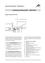
1. Beschreibung<br />
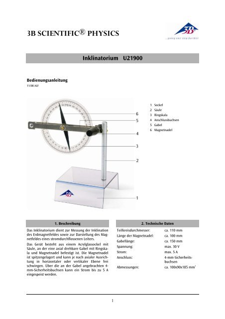
Das Inklinatorium dient zur Messung der Inklination<br />
des Erdmagnetfeldes sowie zur Darstellung des Magnetfeldes<br />
eines stromdurchflossenen Leiters.<br />
Das Gerät besteht aus einem Acrylglassockel mit<br />
Säule, an der eine axial drehbare Gabel mit Ringskala<br />
und Magnetnadel befestigt ist. Die Magnetnadel<br />
ist spitzengelagert und kann je nach axialer Ausrichtung<br />
in horizontaler oder vertikaler Ebene frei<br />
schwingen. Über die an der Gabel angebrachten 4mm-Sicherheitsbuchsen<br />
kann ein Strom bis zu 5 A<br />
eingespeist werden.<br />
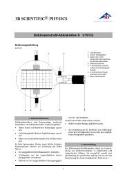
Inklinatorium U21900<br />
1<br />
1 Sockel<br />
2 Säule<br />
3 Ringskala<br />
4 Anschlussbuchsen<br />
5 Gabel<br />
6 Magnetnadel<br />
2. Technische Daten<br />
Teilkreisdurchmesser: ca. 110 mm<br />
Länge der Magnetnadel: ca. 100 mm<br />
Gabellänge: ca. 150 mm<br />
Spannung: max. 30 V<br />
Strom: max. 5 A<br />
Anschluss: 4-mm-Sicherheits-<br />
buchsen<br />
Abmessungen: ca. 100x90x185 mm 3
3. Bedienung<br />
3.1 Allgemeine Hinweise<br />
• Gerät vor Feuchtigkeit und Staub sowie vor mechanischen<br />
Stößen schützen.<br />
• Berühren der Magnetnadel vermeiden.<br />
Die Geometrie der magnetischen Feldlinien der Erde<br />
wird durch statische Magnetfelder, Stahlrahmen in<br />
Labortischen und Einrichtungen, Stahlträger in Böden<br />
Decken und Wänden von Gebäuden mitunter<br />
erheblich verändert. Aus diesem Grund sind größere<br />
Abweichungen von den zu erwartenden Winkeln<br />
nicht auszuschließen.<br />
3.2 Bestimmung der Inklination<br />
Die Magnetnadel richtet sich auf den tatsächlichen<br />
Verlauf der magnetischen Feldlinien der Erde aus.<br />
• Das Gerät bei horizontaler Skalenebene so ausrichten,<br />
dass die blaue Seite der Magnetnadel<br />
auf 0° steht (blaue Seite der Nadel zeigt in Richtung<br />
Norden).<br />
• Danach die Gabel um 90° verstellen (vertikale<br />
Skalenebene). Die Magnetnadel neigt sich nach<br />
unten.<br />
Die Abweichung der Magnetnadel von der Waagerechten<br />
heißt Inklination. Sie ist von Ort zu Ort unterschiedlich<br />
und beträgt bei ca. 50° nördlicher Breite<br />
(Europa) 63° bis 68°.<br />
3.3 Magnetische Wirkung des elektrischen Stromes<br />
Zur Durchführung des Versuchs ist eine regelbare<br />
Gleichstromquelle zusätzlich erforderlich z.B.<br />
1 DC-Netzgerät 0 - 20 V, 0 - 5 A (230 V, 50/60 Hz)<br />
U33020-230<br />
oder<br />
1 DC-Netzgerät 0 - 20 V, 0-5 A (115 V, 50/60 Hz)<br />
U33020-115<br />
• Das Gerät bei horizontaler Skalenebene so ausrichten,<br />
dass die blaue Seite der Magnetnadel<br />
auf 0° steht (blaue Seite der Nadel zeigt in Richtung<br />
Norden).<br />
• Anschlussbuchsen an eine regelbare Gleichstromquelle<br />
anschließen.<br />
Mit wachsender Stromstärke erfährt die Nadel eine<br />
zunehmende Auslenkung.<br />
Bei Wechsel der Polarität ändert sich die Richtung<br />
der Auslenkung.<br />
<strong>3B</strong> Scientific GmbH Rudorffweg 8 21031 Hamburg Deutschland www.3bscientific.com<br />
Technische Änderungen vorbehalten<br />
© Copyright 2008 <strong>3B</strong> Scientific GmbH
<strong>3B</strong> <strong>SCIENTIFIC®</strong> <strong>PHYSICS</strong><br />
Instruction Sheet<br />
11/08 ALF<br />
1. Description<br />
The inclination instrument is used to measure the<br />
inclination of the earth’s magnetic field, and to<br />
demonstrate the magnetic field produced by a<br />
current-carrying conductor.<br />
The instrument consists of a acrylic base with a pillar<br />
which supports an axially rotatable cradle carrying a<br />
magnetic needle and a scale ring. The magnet<br />
needle is mounted on a bearing consisting of sharp<br />
tips, and is free to rotate in either a horizontal or a<br />
vertical plane according to the direction of its axis.<br />
The sockets on the cradle can be used to pass a<br />
current of up to 5 A through it.<br />
Inclination Instrument U21900<br />
1<br />
1 Base<br />
2 Pillar<br />
3 Scale ring<br />
4 Connecting sockets<br />
5 Cradle<br />
6 Magnet needle<br />
2. Technical data<br />
Diameter of circle: approx. 110 mm<br />
Length of magnetic<br />
needle: approx. 100 mm<br />
Cradle length: approx. 150 mm<br />
Voltage: max. 30 V<br />
Current: max. 5 A<br />
Terminal: 4 mm safety sockets<br />
Base dimensions: approx. 100x90x185 mm³
3. Operation<br />
3.1 General precautions<br />
• Protect the instrument from moisture, dust and<br />
mechanical shocks.<br />
• Avoid touching the magnet needle.<br />
The geometry of the earth’s magnetic field lines can<br />
be greatly altered by static magnetic fields, steel<br />
frames of laboratory benches and equipment, and<br />
steel supports in the floor, ceiling and walls of<br />
buildings. For this reason the measured angles may<br />
sometimes differ widely from the expected values.<br />
3.2 Measurement of the inclination<br />
The magnet needle aligns itself along the direction<br />
of the earth’s magnetic field.<br />
• With the scale ring in the horizontal plane, turn<br />
the instrument so that the blue end of the<br />
magnet needle is at 0° (the blue end of the<br />
needle is its north-seeking pole).<br />
• Next turn the cradle through 90° (the plane of<br />
the scale ring is then vertical). The blue end of<br />
the magnet needle is inclined downwards.<br />
The angle between the magnet needle and the<br />
horizontal plane is called the inclination. It differs<br />
from place to place. At a latitude of about 50° north<br />
(Europe) the inclination is 63° to 68°.<br />
3.3 Magnetic effect of an electric current<br />
In order to carry out the experiment, a variable DC<br />
current source is also needed, such as:<br />
1 DC power supply 0 - 20 V, 0 - 5 A (230 V, 50/60 Hz)<br />
U33020-230<br />
or<br />
1 DC power supply 0 - 20 V, 0 - 5 A (115 V, 50/60 Hz)<br />
U33020-115<br />
• With the scale ring in the horizontal plane, turn<br />
the instrument so that the blue end of the<br />
magnet needle (its north-seeking pole) is at 0°.<br />
• Connect the sockets on the instrument to a<br />
variable DC current source.<br />
As the current is increased, the needle is deflected<br />
increasingly from its original direction.<br />
When the polarity is reversed, the direction of the<br />
deflection changes.<br />
<strong>3B</strong> Scientific GmbH Rudorffweg 8 21031 Hamburg Germany www.3bscientific.com<br />
Subject to technical amendments<br />
© Copyright 2008 <strong>3B</strong> Scientific GmbH
<strong>3B</strong> <strong>SCIENTIFIC®</strong> <strong>PHYSICS</strong><br />
Instructions d'utilisation<br />
11/08 ALF<br />
1. Description<br />
Cette boussole permet de mesurer l'inclinaison du<br />
champ magnétique terrestre ainsi que de<br />
représenter le champ magnétique d'un conducteur<br />
traversé par du courant.<br />
L'appareil est constitué d'un socle en verre acrylique<br />
avec une colonne à laquelle est fixée une fourche à<br />
pivotement axiale avec graduation annulaire et<br />
aiguille aimantée. L'aiguille aimantée étant fixée sur<br />
la pointe et pouvant tourner, elle est donc à même<br />
d'osciller librement sur le plan horizontal ou vertical<br />
en fonction de l'orientation axiale respective. Les<br />
bornes disposées sur la fourche permettent<br />
d'alimenter un courant maximum de 5 A.<br />
Boussole d'inclinaison U21900<br />
1<br />
1 Socle<br />
2 Colonne<br />
3 Graduation annulaire<br />
4 Bornes de connexion<br />
5 Fourche<br />
6 Aiguille aimantée<br />
2. Caractéristiques techniques<br />
Diamètre boussole : env. 110 mm<br />
Longueur aiguille<br />
magnétique : env. 100 mm<br />
Longueur fourche : env. 150 mm<br />
Tension : max. 30 V<br />
Courant : max. 5 A<br />
Branchement : douilles de sécurité<br />
de 4 mm<br />
Dimensions : env. 100x90x185 mm³
3. Manipulation<br />
3.1 Notes générales<br />
• Protégez l'appareil contre l'humidité et la<br />
poussière ainsi que les chocs mécaniques.<br />
• Evitez de toucher l'aiguille aimantée.<br />
Souvent, les champs magnétiques statiques, les<br />
cadres en acier dans les tables de laboratoires et les<br />
installations, les poutres métalliques dans les sols,<br />
planchers et murs des bâtiments modifient<br />
sensiblement la géométrie des lignes de champ<br />
magnétiques de la Terre. Aussi est-il tout à fait<br />
possible que les angles escomptés au cours de<br />
l'expérience subissent de fortes variations.<br />
3.2 Déterminer l'inclinaison<br />
L'aiguille aimantée suit l'orientation effective des<br />
lignes de champ magnétiques de la Terre.<br />
• Dans le plan horizontal de la graduation, ajustez<br />
l'appareil de telle sorte que le côté bleu de<br />
l'aiguille aimantée se trouve sur 0° (le côté bleu<br />
de l'aiguille indique la direction du Nord).<br />
• Ensuite tournez la fourche à 90° (plan vertical de<br />
la graduation). L'aiguille aimantée incline son<br />
côté bleu vers le bas.<br />
L'inclinaison est l'écart de l'aiguille aimantée par<br />
rapport à l'horizontale. Variant selon l'emplacement<br />
géographique, elle se situe entre 63 et 68° à environ<br />
50° de latitude Nord (Europe).<br />
3.3 Effet magnétique du courant électrique<br />
Pour réaliser l'expérience, il vous faut encore une<br />
source de courant continu réglable, par ex.<br />
1 Alimentation CC 0 - 20 V, 0 - 5 A (230 V, 50/60 Hz)<br />
U33020-230<br />
ou<br />
1 Alimentation CC 0 - 20 V, 0 - 5 A(115 V, 50/60 Hz)<br />
U33020-115<br />
• Dans le plan horizontal de la graduation, ajustez<br />
l'appareil de telle sorte que le côté bleu de<br />
l'aiguille aimantée se trouve sur 0° (le côté bleu<br />
de l'aiguille indique la direction du Nord).<br />
• Branchez les bornes de connexion à une source<br />
de courant continu réglable.<br />
La déviation de l'aiguille augmente au fur et à<br />
mesure que l'intensité électrique devient plus<br />
importante.<br />
Si vous modifiez la polarité, la déviation changera de<br />
direction.<br />
<strong>3B</strong> Scientific GmbH ▪ Rudorffweg 8 ▪ 21031 Hamburg ▪ Allemagne ▪ www.3bscientific.com<br />
Sous réserve de modifications techniques<br />
© Copyright 2008 <strong>3B</strong> Scientific GmbH
<strong>3B</strong> <strong>SCIENTIFIC®</strong> <strong>PHYSICS</strong><br />
Istruzioni per l'uso<br />
11/08 ALF<br />
1. Descrizione<br />
L’inclinatorio serve per la misurazione dell’in-<br />
clinazione del campo magnetico terrestre e per la<br />
rappresentazione del campo magnetico di un<br />
conduttore percorso da corrente.<br />
L’apparecchio è composto da una base acrilica con<br />
colonna, alla quale è fissata una staffa girevole sul<br />
proprio asse munita di cerchio graduato e ago<br />
magnetico. L’ago magnetico è sospeso su un perno e<br />
può oscillare liberamente sul piano orizzontale o<br />
verticale in base all’orientamento assiale. Attraverso<br />
i jack applicati sulla staffa è possibile alimentare una<br />
corrente max. di 5 A.<br />
Inclinatorio U21900<br />
1<br />
1 Base<br />
2 Colonna<br />
3 Cerchio graduato<br />
4 Jack di raccordo<br />
5 Staffa<br />
6 Ago magnetico<br />
2. Dati tecnici<br />
Diametro cerchio<br />
graduato: ca. 110 mm<br />
Lunghezza dell’ago<br />
magnetico: ca. 100 mm<br />
Lunghezza staffa: ca. 150 mm<br />
Tensione: max. 30 V<br />
Corrente: max. 5 A<br />
Allacciamento: jack di sicurezza da 4 mm<br />
Dimensioni: ca. 100x90x185 mm³
3. Utilizzo<br />
3.1 Indicazioni generali<br />
• Proteggere l’apparecchio da polvere, umidità e<br />
urti meccanici.<br />
• Evitare di toccare l’ago magnetico.<br />
La geometria delle linee del campo magnetico<br />
terrestre viene talvolta notevolmente modificata da<br />
campi magnetici statici, strutture in acciaio dei tavoli<br />
e dispositivi di laboratorio, travi di acciaio nel<br />
pavimento, nelle pareti e nei soffitti degli edifici. Per<br />
questo motivo non è possibile escludere<br />
considerevoli variazioni rispetto agli angoli previsti.<br />
3.2 Determinazione dell’inclinazione<br />
L’ago magnetico si orienta sull’effettivo andamento<br />
delle linee del campo magnetico terrestre.<br />
• Con il cerchio graduato in posizione orizzontale,<br />
orientare l’apparecchio in modo che il lato blu<br />
dell’ago magnetico sia posizionato in<br />
•<br />
corrispondenza di 0° (il lato blu dell’ago deve<br />
essere rivolto a nord).<br />
Quindi ruotare di 90° la staffa (scala graduata<br />
verticale). L’ago magnetico si orienta con il lato<br />
blu rivolto verso il basso.<br />
La deviazione dell’ago magnetico rispetto al piano<br />
orizzontale è chiamata inclinazione. È diversa da<br />
località a località e a ca. 50° di latitudine nord<br />
(Europa) è compresa tra 63° e 68°.<br />
3.3 Effetto magnetico della corrente elettrica<br />
Per l’esecuzione dell’esperimento è necessaria una<br />
sorgente di corrente continua regolabile<br />
supplementare.<br />
Alimentatore CC 0 - 20 V, 0 - 5 A (230 V, 50/60 Hz)<br />
U33020-230<br />
oppure<br />
Alimentatore CC 0 - 20 V, 0 - 5 A (115 V, 50/60 Hz)<br />
U33020-115<br />
• Con il cerchio graduato in posizione orizzontale,<br />
orientare l’apparecchio in modo che il lato blu<br />
dell’ago magnetico sia posizionato in<br />
•<br />
corrispondenza di 0° (lato blu dell’ago deve<br />
essere rivolto a nord).<br />
Collegare i jack di raccordo a una sorgente di<br />
corrente continua regolabile.<br />
Alla variazione dell’intensità della corrente l’ago<br />
subisce una deviazione crescente.<br />
In caso di cambio di polarità, cambia anche la<br />
direzione della deviazione.<br />
<strong>3B</strong> Scientific GmbH ▪ Rudorffweg 8 ▪ 21031 Amburgo ▪ Germania ▪ www.3bscientific.com<br />
Con riserva di modifiche tecniche<br />
© Copyright 2008 <strong>3B</strong> Scientific GmbH
<strong>3B</strong> <strong>SCIENTIFIC®</strong> <strong>PHYSICS</strong><br />
Instrucciones de uso<br />
11/08 ALF<br />
1. Descripción<br />
El inclinatorio sirve para la medición de la<br />
inclinación local del campo magnético terrestre así<br />
como para la representación del campo magnético<br />
de un conductor que lleva corriente.<br />
El aparato se compone de un zócalo de cristal<br />
acrílico con una columna en la cual se tiene fija una<br />
horquilla de giro axial con escala circular y aguja<br />
magnética. La aguja magnética esta soportada en<br />
puntas y puede oscilar libremente en el plano<br />
horizontal o en el vertical, dependiendo de la<br />
orientación axial. Por medio de los casquillos fijos en<br />
la horquilla se puede suministrar una corriente de<br />
hasta 5 A.<br />
Inclinatorio U21900<br />
1<br />
1 Zócalo<br />
2 Columna<br />
3 Escala circular<br />
4 Casquillos de conexión<br />
5 Horquilla<br />
6 Aguja magnética<br />
2. Datos técnicos<br />
Diámetro del círculo<br />
graduado: aprox. 110 mm<br />
Longitud de la aguja<br />
magnética: aprox. 100 mm<br />
Longitud de la horquilla: aprox. 150 mm<br />
Tensión: max. 30 V<br />
Corriente: max. 5 A<br />
Conexión: casquillos de seguridad<br />
de 4 mm<br />
Dimensiones: aprox. 100x90x185 mm³
3. Manejo<br />
3.1 Advertencias generales<br />
• Proteja los aparatos contra humedad, polvo y<br />
golpes mecánicos.<br />
• Evite tocar la aguja magnética.<br />
La geometría de las líneas del campo magnético<br />
terrestre se cambia fuertemente por campos<br />
magnéticos estáticos, marcos de acero en mesas de<br />
laboratorio e instalaciones, vigas de acero en el<br />
suelo, en techos y paredes de edificaciones. Por esta<br />
razón no se puede evitar tener desviaciones en los<br />
ángulos a esperar.<br />
3.2 Determinación de la inclinación<br />
La aguja se orienta a lo largo de la dirección del<br />
curso real de las líneas de campo magnético<br />
terrestre.<br />
• Teniendo el plano de escala horizontalmente, el<br />
lado azul de la aguja se orienta en dirección<br />
norte, la aguja se orienta de tal forma que ésta<br />
se encuentra en 0° (lado azul de la aguja<br />
muestra en dirección norte).<br />
• Luego, se gira la horquilla en 90° (plano vertical<br />
de la escala). La aguja magnética se inclina con<br />
el lado azul hacia abajo.<br />
La desviación de la aguja magnética con respecto a<br />
la horizontal se llama inclinación. Ésta es diferente<br />
de lugar en lugar y en el paralelo de latitud norte de<br />
aprox. 50° (Europa) se encuentra entre 63° y 68°.<br />
3.3 Efecto magnético de la corriente eléctrica<br />
Para la realización del experimento se requiere<br />
adicionalmente una fuente de corriente continua<br />
regulable, por ejemplo:<br />
Fuente de CC 0 - 20 V, 0 - 5 A (230 V, 50/60 Hz)<br />
U33020-230<br />
o<br />
Fuente de CC 0 - 20 V, 0 - 5 A (115 V, 50/60 Hz)<br />
U33020-115<br />
• Teniendo el plano de escala horizontalmente, el<br />
lado azul de la aguja se debe orientar de tal<br />
forma que ésta se encuentre en 0° (lado azul de<br />
la aguja muestra en dirección del norte).<br />
• Los casquillos de conexión se conectan a una<br />
fuente de corriente continua regulable.<br />
Al aumentar la intensidad de corriente, la aguja<br />
magnética experimenta una desviación adicional.<br />
Al cambiar la polaridad de la fuente cambia el<br />
sentido de la desviación.<br />
<strong>3B</strong> Scientific GmbH Rudorffweg 8 21031 Hamburgo Alemania www.3bscientific.com<br />
Nos reservamos el derecho a cambios técnicos<br />
© Copyright 2008 <strong>3B</strong> Scientific GmbH
<strong>3B</strong> <strong>SCIENTIFIC®</strong> FÍSICA<br />
Manual de instruções<br />
11/08 ALF<br />
1. Descrição<br />
O inclinatório serve para medir a inclinação do campo<br />
magnético da terra, bem como para a representação<br />
de um campo magnético de um condutor elétrico.<br />
O aparelho é constituído de uma base de acrílico com<br />
um pilar, na qual esta fixada um garfo giratório com<br />
uma escala anelar e uma agulha magnética. A agulha<br />
magnética tem um mancal cônico e pode oscilar<br />
livremente de acordo à orientação axial em plano<br />
horizontal ou vertical. Sobre as tomadas no garfo,<br />
pode-se conduzir uma energia de até 5 A.<br />
Inclinatório U21900<br />
1<br />
1 Base<br />
2 Pilar<br />
3 Escala anelar<br />
4 Tomadas<br />
5 Garfo<br />
6 Agulha magnética<br />
2. Dados técnicos<br />
Diâmetro do círculo<br />
de referência: aprox. 110 mm<br />
Comprimento da<br />
agulha magnética: aprox. 100 mm<br />
Comprimento do garfo: aprox. 150 mm<br />
Tensão: máx. 30 V<br />
Corrente: máx. 5 A<br />
Conexão elétrica: tomadas de segurança<br />
de 4 mm<br />
Dimensões: aprox. 100x90x185 mm³
3. Operação<br />
3.1 Dicas gerais<br />
• Proteger o aparelho da umidade, poeira e batidas<br />
mecânicas.<br />
• Evitar o contato com a agulha magnética.<br />
A geometria dos campos magnéticos da terra pode ser<br />
alterada através de campos magnéticos estáticos,<br />
molduras de aço em mesas de laboratórios e<br />
acessórios, condutores de aço em paredes, chão e<br />
tetos de construções. Por este motivo não pode ser<br />
excluído o desvio do ângulo esperado.<br />
3.2 Determinação da inclinação<br />
A agulha magnética aponta para o real campo<br />
magnético da terra.<br />
• Direcionar o aparelho, na escala horizontal, de<br />
modo que o lado azul da agulha magnética<br />
aponte para 0° (o lado azul da agulha aponta<br />
para a direção norte).<br />
• Depois movimentar o garfo para 90° (nível de<br />
escala vertical). A agulha magnética tende, com<br />
sua parte azul, para baixo.<br />
O desvio da agulha magnética da sua posição<br />
horizontal determina a inclinação. Ela altera-se de<br />
lugar para lugar e em aprox. 50° de largura norte<br />
(Europa) varia de 63° a 68°.<br />
3.3 Efeito magnético de uma corrente Elétrica<br />
Para proceder com o experimento é necessária uma<br />
fonte de energia estável adicional como por exemplo.<br />
Fonte de alimentação 0 - 20 V, 0 - 5 A (230 V, 50/60 Hz)<br />
U33020-230<br />
ou<br />
Fonte de alimentação 0- 20 V, 0 - 5 A (115 V, 50/60 Hz)<br />
U33020-115<br />
• Direcionar o aparelho, na escala horizontal, de<br />
modo que o lado azul da agulha magnética<br />
aponte para 0° (o lado azul da agulha aponta<br />
para a direção norte).<br />
• Ligar as tomadas em uma fonte de alimentação<br />
regulável.<br />
Com o aumento da corrente elétrica a agulha<br />
presencia um desvio gradual.<br />
Ao se inverter a polaridade presencia-se o desvio<br />
inverso da direção.<br />
<strong>3B</strong> Scientific GmbH ▪ Rudorffweg 8 ▪ 21031 Hamburgo ▪ Alemanha ▪ www.3bscientific.com<br />
Sob reserva de alterações técnicas<br />
© Copyright 2008 <strong>3B</strong> Scientific GmbH