INSTALLATION MANUAL - Daikin AC
INSTALLATION MANUAL - Daikin AC
INSTALLATION MANUAL - Daikin AC

You also want an ePaper? Increase the reach of your titles
YUMPU automatically turns print PDFs into web optimized ePapers that Google loves.
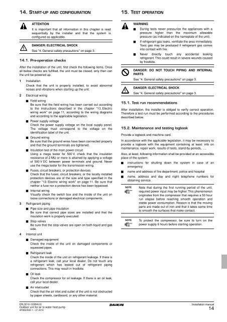
14. START-UP AND CONFIGURATION15. TEST OPERATIONATTENTIONIt is important that all information in this chapter is readsequentially by the installer and that the system isconfigured as applicable.DANGER: ELECTRICAL SHOCKSee "4. General safety precautions" on page 3.14.1. Pre-operation checksAfter the installation of the unit, first check the following items. Onceall below checks are fulfilled, the unit must be closed, only then canthe unit be powered up.1 InstallationCheck that the unit is properly installed, to avoid abnormalnoises and vibrations when starting up the unit.2 Electrical wiring■ Field wiringBe sure that the field wiring has been carried out accordingto the instructions described in the chapter "13. Electricwiring work" on page 11, according to the wiring diagramsand according to the applicable legislation.■ Power supply voltageCheck the power supply voltage on the local supply panel.The voltage must correspond to the voltage on theidentification label of the unit.■ Ground wiringBe sure that the ground wires have been connected properlyand that the ground terminals are tightened.■ Insulation test of the main power circuitUsing a mega tester for 500 V, check that the insulationresistance of 2 MΩ or more is attained by applying a voltageof 500 V DC between power terminals and ground. Neveruse the mega tester for the transmission wiring.■ Fuses, circuit breakers, or protection devicesCheck that the fuses, circuit breakers, or the locally installedprotection devices are of the size and type specified in thechapter "13. Electric wiring work" on page 11. Be sure thatneither a fuse nor a protection device has been bypassed.■ Internal wiringVisually check the switch box and the inside of the unit onloose connections or damaged electrical components.3 Refrigerant piping■ Pipe size and pipe insulationBe sure that correct pipe sizes are installed and that theinsulation work is properly executed.■ Stop valvesBe sure that the stop valves are open on both liquid and gasside.4 Internal unit■ Damaged equipmentCheck the inside of the unit on damaged components orsqueezed pipes.■ Refrigerant leakCheck the inside of the unit on refrigerant leakage. If there isa refrigerant leak, call your local dealer. Do not touch anyrefrigerant which has leaked out of refrigerant pipingconnections. This may result in frostbite.■ Oil leakCheck the compressor for oil leakage. If there is an oil leak,call your local dealer.■ Air inlet/outletCheck that the air inlet and outlet of the unit is not obstructedby paper sheets, cardboard, or any other material.WARNING■ During tests never pressurize the appliances with apressure higher than the maximum allowablepressure (as indicated on the nameplate of the unit).■ If refrigerant gas leaks, ventilate the area immediately.Toxic gas may be produced if refrigerant gas comesinto contact with fire.■ Never directly touch any accidental leakingrefrigerant. This could result in severe wounds causedby frostbite.DANGER: DO NOT TOUCH PIPING AND INTERNALPARTSSee "4. General safety precautions" on page 3.15.1. Test run recommendationsAfter installation, the installer is obliged to verify correct operation.Therefore a test run must be performed according to the proceduresdescribed below.15.2. Maintenance and testing logbookProvide a logbook and machine card.In accordance with the applicable legislation, it may be necessary toprovide a logbook with the equipment containing at least: info onmaintenance, repair work, results of tests, stand-by periods, ….Also, at least, following information shall be provided at an accessibleplace of the system:■ instructions for shutting down the system in case of anemergency■ name and address of fire department, police and hospital■ name, address and day and night telephone numbers forobtaining service.NOTENOTEDANGER: ELECTRICAL SHOCKSee "4. General safety precautions" on page 3.Note that during the first running period of the unit,required power input may be higher. This phenomenonoriginates from the compressor that requires a 50 hourrun elapse before reaching smooth operation andstable power consumption. Reason is that the movingparts are made out of iron and that it takes some timeto smooth the surfaces that make contact.To protect the compressor, be sure to turn on thepower supply 6 hours before starting operation.ERLQ018~030BAVJUOutdoor unit for air to water heat pump4PW62590-1 – 07.2010Installation manual14