TV Explorer HD ISDB-T/Tb manual - Promax
TV Explorer HD ISDB-T/Tb manual - Promax
TV Explorer HD ISDB-T/Tb manual - Promax

You also want an ePaper? Increase the reach of your titles
YUMPU automatically turns print PDFs into web optimized ePapers that Google loves.
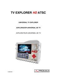
<strong>TV</strong> EXPLORER <strong>HD</strong> <strong>ISDB</strong>-T/T BEXPLORADOR UNIVERSAL DE <strong>TV</strong>UNIVERSAL <strong>TV</strong> EXPLORER- 0 MI1932 -
NOTAS SOBRE SEGURIDADAntes de manipular el equipo leer el <strong>manual</strong> de instrucciones y muyespecialmente el apartado PRESCRIPCIONES DE SEGURIDAD.El símbolo sobre el equipo significa "CONSULTAR EL MANUAL DEINSTRUCCIONES". En este <strong>manual</strong> puede aparecer también como símbolo deadvertencia o precaución.Recuadros de ADVERTENCIAS Y PRECAUCIONES pueden aparecer a lo largo deeste <strong>manual</strong> para evitar riesgos de accidentes a personas o daños al equipo uotras propiedades.SAFETY NOTESRead the user’s <strong>manual</strong> before using the equipment, mainly " SAFETY RULES "paragraph.The symbol on the equipment means "SEE USER’S MANUAL". In this<strong>manual</strong> may also appear as a Caution or Warning symbol.Warning and Caution statements may appear in this <strong>manual</strong> to avoid injuryhazard or damage to this product or other property.
EnglishSUMARIOCONTENTS Manual español............................................................. English <strong>manual</strong>.............................................................
MANUAL DE INSTRUCCIONES. <strong>TV</strong> EXPLORER <strong>HD</strong> <strong>ISDB</strong>-T/T B5.14.7.3 Señales <strong>ISDB</strong>-T/T B ............................................................................ 615.14.7.4 Señales DVB-S/S2............................................................................. 635.14.8 <strong>TV</strong> Digital: Medida del MER........................................................................ 665.15 Diagrama de Constelación ................................................................................ 685.15.1 Señal <strong>ISDB</strong>-T/T B (COFDM) ........................................................................ 685.15.1.1 Funciones de zoom, scroll y borrado ................................................. 705.15.2 Señal DVB-C (QAM) ................................................................................... 705.15.3 Señal DVB-S/S2 (QPSK/8PSK).................................................................. 715.16 Analizador de Espectros ................................................................................... 725.16.1 Marcadores ................................................................................................. 745.16.2 Espectrograma............................................................................................ 755.16.2.1 Configuración de Espectrograma ...................................................... 775.16.2.2 Recuperar un archivo Espectrograma ............................................... 785.16.2.3 Borrar un archivo Espectrograma ...................................................... 795.17 Capturar pantallas ............................................................................................. 795.17.1 Recuperar pantallas capturadas ................................................................. 795.17.2 Borrar pantallas capturadas........................................................................ 805.18 Función PRINT SCREEN.................................................................................. 805.19 Función VER IMPRESIONES PANTALLA........................................................ 815.20 Función USB On-the-Go ................................................................................... 815.20.1 Conexión del <strong>TV</strong> EXPLORER <strong>HD</strong> <strong>ISDB</strong>-T/T B (host) a una memoria USB (slave).. 825.20.2 Conexión de un ordenador (host) al <strong>TV</strong> EXPLORER <strong>HD</strong> <strong>ISDB</strong>-T/T B (slave) ...... 845.21 Configuración de la Entrada-Salida TS-ASI...................................................... 855.22 Visualización de la señal de vídeo .................................................................... 865.22.1 Grabación y reproducción de secuencias de vídeo.................................... 915.23 Función Alinear Antenas ................................................................................... 925.24 Generador de Comandos DiSEqC .................................................................... 935.25 Función SatCR .................................................................................................. 955.26 Utilización del teclado alfanumérico.................................................................. 966 DESCRIPCIÓN DE ENTRADAS Y SALIDAS ......................................................... 976.1 Entrada de RF ................................................................................................... 976.2 Salida / Entrada TS-ASI .................................................................................... 976.3 Puerto USB ....................................................................................................... 976.4 Conector <strong>HD</strong>MI (High-Definition Multimedia-Interface)..................................... 976.5 Euroconector (DIN EN 50049) .......................................................................... 986.6 Adaptador RCA ................................................................................................. 996.7 Conector para módulos CAM y tarjetas SMART-CARD ................................... 997 MANTENIMIENTO................................................................................................. 1017.1 Consideraciones sobre el monitor TFT ........................................................... 1017.2 Recomendaciones de Limpieza ...................................................................... 101
MANUAL DE INSTRUCCIONES. <strong>TV</strong> EXPLORER <strong>HD</strong> <strong>ISDB</strong>-T/T BEXPLORADOR DE <strong>TV</strong> UNIVERSAL<strong>TV</strong> EXPLORER ® <strong>HD</strong> <strong>ISDB</strong>-T/T B11 GENERALIDADES1.1 DescripciónEl explorador de televisión <strong>TV</strong> EXPLORER <strong>HD</strong> <strong>ISDB</strong>-T/T B representa un pasoevolutivo respecto a los medidores de campo tradicionales. Esta nueva joya de la gamade medidores PROMAX está destinada a convertirse en un referente de la industria,por ser el auténtico primer medidor de su clase que cumple con los requisitos para seracreditado como un verdadero instrumento <strong>HD</strong><strong>TV</strong>. PROMAX continua innovando en elsector de los medidores de campo presentando un equipo que cambia la forma dehacer y entender las medidas de las señales de televisión.Este equipo incorpora importantes avances tanto en los aspectos funcionalescomo en la ergonomía para permitir a los instaladores realizar su trabajo con lamáxima comodidad y rapidez. A la vez el instrumento resulta fiable ante cualquierposible problema de la señal de entrada, en los componentes de distribución o enlos equipos de recepción.En estos momentos, para millones de hogares la desconexión analógica ya esuna realidad, dado que hace tiempo que disfrutan de señales exclusivamente digitales.Para estos, y para aquellos que aún se encuentran en el proceso de migración a latecnología digital, el uso de equipos de distribución digital será más frecuente día a día.Los formatos más populares de alta definición utilizados en las retransmisiones detelevisión son 1080i (1920x1080 píxeles) y 720p (1280x720 píxeles). La mayoría de losprogramas que utilizan estas resoluciones de vídeo están comprimidos en formatoMPEG-4. El <strong>TV</strong> EXPLORER <strong>HD</strong> <strong>ISDB</strong>-T/T B es capaz de decodificar estos programasde televisión gracias a su avanzada tecnología.Los contenidos <strong>HD</strong><strong>TV</strong> son caros de producir, y por lo tanto es normal que esténprotegidos con sistemas de encriptación. De nuevo, el <strong>TV</strong> EXPLORER <strong>HD</strong> <strong>ISDB</strong>-T/T Bmarca nuevos estándares con su interfaz CAM, que le permite decodificar programasencriptados.<strong>TV</strong> EXPLORER ® es una marca registrada de PROMAX Electronica S. L.1Trademark of the DVB - Digital Video Broadcasting Project.03/2012 Página 1
MANUAL DE INSTRUCCIONES. <strong>TV</strong> EXPLORER <strong>HD</strong> <strong>ISDB</strong>-T/T BEl <strong>TV</strong> EXPLORER <strong>HD</strong> <strong>ISDB</strong>-T/T B dispone de un conector <strong>HD</strong>MI (High-DefinitionMulti-media Interface) que permite el uso de vídeo estándar, mejorado o de altadefinición, así como 8 canales de audio digital sin comprimir. Sin duda, se convertirá enel sustituto digital de los estándares analógicos como el Euroconector.El <strong>TV</strong> EXPLORER <strong>HD</strong> <strong>ISDB</strong>-T/T B dispone también de un interfaz estándarDVB-ASI, que permite tanto la entrada de tramas de transporte como la salida. Detectaautomáticamente si la trama esta compuesta por 188 o 204 bytes, y puede transmitir enmodo paquete o en modo burst. Se puede seleccionar la entrada que se deseadecodificar entre el ASI externo y el demodulador interno, y qué datos se desean en lasalida ASI, los que provienen del demodulador o del TS AUXILIAR. Por tanto, disponerde entradas y salidas TS-ASI se convierte en una característica fundamental para unanalizador de <strong>TV</strong> preparado para el futuro.Al activar la función de identificación automática, pulsando una sola tecla, elequipo trata de identificar la señal bajo prueba. Primero averigua si se trata de uncanal analógico o digital. Si el canal es analógico, determina el tipo de estándar de laseñal detectada. Si es digital (<strong>ISDB</strong> / DVB), analiza para cada tipo de modulación QAM/ QPSK / 8PSK todos los parámetros asociados: symbol rate, code rate, etc.,. ydetermina los valores en la señal bajo prueba.El margen de frecuencias cubiertas le convierten en un instrumento excelentepara aplicaciones en Radio FM, <strong>TV</strong> terrestre, <strong>TV</strong> móvil, <strong>TV</strong> satélite y <strong>TV</strong> por cable(donde el margen de sintonía de sub-banda, de 5 a 45 MHz, permite realizar tests en elcanal de retorno).El <strong>TV</strong> EXPLORER <strong>HD</strong> <strong>ISDB</strong>-T/T B acepta los sistemas de televisión NTSC yPAL M y N, permite trabajar directamente con señales de <strong>TV</strong> digital descodificándolaspara visualizar la imagen de televisión y para las cuales proporciona directamente lamedida de potencia, de la relación portadora a ruido (C/N), de la tasa de error de laseñal digital (BER) y de la relación de error de modulación (MER), tanto para señales<strong>ISDB</strong>-T/T B (COFDM) como DVB-S/S2 (QPSK/8PSK) y DVB-C/ANNEX-B (QAM). Elequipo también permite obtener una representación gráfica del Diagrama deConstelación tanto para señales DVB-C/ANNEX-B (QAM) como <strong>ISDB</strong>-T/T B yDVB-S/S2 (QPSK/8PSK).Al ser un equipo multiestándar, puede ser utilizado eficientemente en cualquierade los países que utiliza el estandar <strong>ISDB</strong>-T, como Brasil, Venezuela, Chile, etc...Incorpora un teclado iconográfico que permite el acceso directo a las funcionesque aparecen en la pantalla de una forma intuitiva.El <strong>TV</strong> EXPLORER <strong>HD</strong> <strong>ISDB</strong>-T/T B realiza una exploración del espectro,detectando todas las emisiones que se encuentran en la banda explorada, ya seaterrestre o satélite. La exploración del espectro, se efectúa sobre la canalización queen este momento esté seleccionada. Crea una nueva canalización con los nuevosparámetros encontrados para cada canal.Página 2 03/2012
MANUAL DE INSTRUCCIONES. <strong>TV</strong> EXPLORER <strong>HD</strong> <strong>ISDB</strong>-T/T BEn el panel frontal aparece indicado el tipo de medida que se realiza (Terrestre-Satélite / Analógico-Digital) y los datos son visualizados mediante una pantalla gráficaTFT color transflectiva en alta resolución de 6,5” y formato panorámico (16:9). El equipoincorpora un sensor para el ajuste automático del contraste y la luminosidad de lapantalla de acuerdo con las condiciones ambientales presentes en cada momento.En el caso del <strong>TV</strong> EXPLORER <strong>HD</strong> <strong>ISDB</strong>-T/T B se ha provisto al equipo de unconector para módulos CAM (PC-Card) que permite la inserción de tarjetas de accesocondicional de abonado.El tamaño compacto y peso ligero del <strong>TV</strong> EXPLORER <strong>HD</strong> <strong>ISDB</strong>-T/T B permitenque sea manejado con una sola mano. Utilizando la funda o cinta de transportesuministrada el equipo puede sujetarse al cuerpo a la vez que es protegido de lasinclemencias ambientales. El protector anti-choque proporciona una robustezadicional para los trabajos de campo, disponiendo de una maleta rígida de transporte.Además el equipo ha sido diseñado para impedir la entrada accidental de líquidos.El <strong>TV</strong> EXPLORER <strong>HD</strong> <strong>ISDB</strong>-T/T B está diseñado para integrar medidas querequieren configuraciones de operación muy diferentes. De este modo incorpora unafunción específica para facilitar el apuntamiento de antenas. Al activarla elinstrumento se configura automáticamente para ofrecer un barrido del espectro muyrápido y una barra gráfica de alta sensibilidad permite el ajuste fino de los máximosde señal. Además incluye un módulo para la alimentación de LNBs, y antenas<strong>ISDB</strong>-T/T B a 5 V. Así como comandos para la programación de dispositivos DiSEqC1.2 y SatCR.El <strong>TV</strong> EXPLORER <strong>HD</strong> <strong>ISDB</strong>-T/T B permite una actualización sencilla a nuevasversiones de software que amplíen en un futuro las funciones disponibles. De estamanera puede incorporar nuevas prestaciones sin coste adicional. Como por ejemplo,la verificación de las redes de distribución de señales satélite. Su utilización encombinación con un generador de FI facilita una comprobación sencilla de lasinstalaciones antes de su entrada en servicio.El analizador de espectros que incorpora el <strong>TV</strong> EXPLORER <strong>HD</strong> <strong>ISDB</strong>-T/T Bdestaca por la precisión, resolución, sensibilidad y velocidad de barrido que le hacenser muy útil para aplicaciones de instalación de antenas. Presenta un innovadorsistema de control de la representación mediante flechas de cursor que hace muyintuitiva la utilización de la función analizador de espectros. Las flechas permitenajustar el nivel de referencia en pasos de 5 ó 10 dB y el span del margen defrecuencias en pantalla.03/2012 Página 3
MANUAL DE INSTRUCCIONES. <strong>TV</strong> EXPLORER <strong>HD</strong> <strong>ISDB</strong>-T/T BPara una mayor comodidad de uso, dispone de memorias para almacenaradquisiciones de medidas automáticamente, registrando: nombre de la adquisición,punto de la medida, frecuencia, tabla de canales, etc. La función ADQUISICIÓN facilitaenormemente la verificación de sistemas donde se requiere realizar un elevado númerode medidas y posibilita un posterior procesado de toda la información adquirida en unordenador personal. El equipo ofrece la posibilidad de generar informes de medidasautomáticos y de actualizarse a través de Internet mediante el software PkToolsincluido.El <strong>TV</strong> EXPLORER <strong>HD</strong> <strong>ISDB</strong>-T/T B además permite grabar y reproducir un serviciodel TS del canal digital que se esta demodulando mediante una memoria interna dehasta 1 GB.Además el equipo incorpora un generador de comandos DiSEqC 2 y permitesuministrar diversas tensiones a la unidad externa (5 V / 13 V / 15 V / 18 V / 24 V).También se ha provisto al equipo de un EUROCONECTOR, o conector Scart, conentrada/salida de audio/vídeo.El <strong>TV</strong> EXPLORER <strong>HD</strong> <strong>ISDB</strong>-T/T B se alimenta mediante batería recargable oconectado a la red mediante el alimentador DC externo suministrado.Incorpora un puerto “USB On-the-go“ para facilitar la comunicación con un PC yla descarga de canalizaciones y adquisiciones automáticas.Este equipo debido a su diseño ultra-compacto, especificaciones técnicas y bajocoste se convierte en el instrumento de referencia para el instalador.1.2 EspecificacionesCONFIGURACIÓN PARA MEDIDA DE NIVEL Y POTENCIASINTONÍASíntesis digital de frecuencia. Sintonía continua de5 a 1000 MHz y de 950 a 2150 MHz (Terrestre ySatélite respectivamente).Modos de sintoníaCanal o Frecuencia (FI o directa en banda satélite).Plan de canalesConfigurable para cada sesión.Resolución 5-1000 MHz: 50 kHz.950-2150 MHz: < 200 kHz (span FULL-500-200-100-50-32-16 MHz).Búsqueda automática (<strong>Explorer</strong>) Nivel umbral seleccionable. Selección <strong>ISDB</strong>-T/T B ,ITU-T J.83/B, DVB-C Annex A & B, DVB-S,DVB-S2 y DSS.Identificación de señales Analógicas y digitales. Automática.2 DiSEqC TM es una marca registrada de EUTELSATPágina 4 03/2012
MANUAL DE INSTRUCCIONES. <strong>TV</strong> EXPLORER <strong>HD</strong> <strong>ISDB</strong>-T/T BENTRADA DE RFImpedancia 75 Ω.Conector Universal, con adaptador BNC o F.Máxima señalMáxima tensión de entradaDC a 100 Hz130 dBµV.5 MHz a 2150 MHz 130 dBµV.MEDIDA DE SEÑALES DIGITALESMARGEN DE MEDIDA DE POTENCIA<strong>ISDB</strong>-T/T B :45 dBµV a 100 dBµV.QAM Annex-B/-A:45 dBµV a 110 dBµV.QPSK/8PSK:44 dBµV a 114 dBµV.DSS:44 dBµV a 114 dBµV.MEDIDAS<strong>ISDB</strong>-T/T B :PresentaciónITU-T J.83/B(QAM ANNEX-B):Presentación:DVB-C (QAM):Presentación:DVB-S (QPSK):Presentación:DVB-S2 (QPSK/8PSK):Presentación:DSS (QPSK):Presentación:50 V rms (alimentado por el cargador AL-103).30 V rms (no alimentado por el cargador AL-103).Potencia, CBER, VBER, MER, C/N, Margen deruido.Numérica y barra de nivel.Potencia, BER, MER, C/N y Margen de ruido.Numérica y barra de nivel.Potencia, BER, MER, C/N y Margen de ruido.Numérica y barra de nivel.Potencia, CBER, VBER, MER, C/N y Margen de ruido.Numérica y barra de nivel.Potencia, CBER, LBER, MER, C/N, paquetes erróneos yLink Margin.Numérica y barra de nivel.Potencia, CBER, VBER, MER, C/N y Margen de ruido.Numérica y barra de nivel.DIAGRAMA DE CONSTELACIÓNTipo de señal DVB-C, DVB-S, DVB-S2, QAM-B/-A y <strong>ISDB</strong>-T/T B .PresentaciónGráfico I-Q.PARÁMETROS SEÑAL <strong>ISDB</strong>-T/T BCode Rate 2/3, 1/2, 3/4, 5/6, 7/8.Inversión espectralSeleccionable: ON, OFF.DemodulaciónDQPSK, QPSK, 16QAM, 64QAM.Segmentos 1..13.Capa A, B, C.Modo1 (2k), 2 (4k), 3 (8k).Guarda 1/4, 1/8, 1/16, 1/32.03/2012 Página 5
MANUAL DE INSTRUCCIONES. <strong>TV</strong> EXPLORER <strong>HD</strong> <strong>ISDB</strong>-T/T BPARÁMETROS SEÑAL ITU-T J.83/BDemodulación64/256 QAM.Velocidad de símbolo 5057 / 5361 kbauds.Factor de roll-off (α) delfiltro de Nyquist 0,18/0,12.Inversión espectralSeleccionable: ON, OFF.PARÁMETROS SEÑAL DVB-CDesmodulación16/32/64/128/256 QAM.Velocidad de símbolo 1000 a 7000 kbauds.Factor de roll-off (α) delfiltro de Nyquist 0,15.Inversión espectralSeleccionable: ON, OFF.PARÁMETROS SEÑAL DVB-SVelocidad de símbolo 2 a 45 Mbauds.Factor de roll-off (α) delfiltro de Nyquist 0,35.Code Rate1/2, 2/3, 3/4, 5/6, 7/8 y AUTO.Inversión espectralSeleccionable: ON, OFF.PARÁMETROS SEÑAL DVB-S2Velocidad de símbolo (QPSK) 1 a 45 MSps.Velocidad de símbolo (8PSK) 1 a 45 MSps.Factor de roll-off (α) delfiltro de Nyquist 0,20, 0,25 y 0,35.Code Rate (QPSK)1/4, 1/3, 2/5, 1/2, 3/5, 2/3, 3/4, 4/5, 5/6, 8/9, 9/10 y AUTO.Code Rate (8PSK)3/5, 2/3, 3/4, 5/6, 8/9, 9/10 y AUTO.Inversión espectralSeleccionable: ON, OFF.PilotosIndicación presencia.PARÁMETROS SEÑAL DSSVelocidad de símbolo 20 Mbauds.Factor de roll-off (α) delfiltro de Nyquist 0,20.Code Rate1/2, 2/3, 6/7 y AUTO.Inversión espectralSeleccionable: ON, OFF.VÍDEO ESTÁNDARFormatoDescodificación serviciosMPEG-2 (MP@HL) (Main Profile High Level).MPEG-4 AVC H.264 (High Profile Level 4.1).Lista de servicios y PIDs.VÍDEO <strong>HD</strong>Resolución de entrada 1080i, 720p y 576i.Formatos de pantalla 16:9 y 4:3.Resolución salida <strong>HD</strong>MI 1920 x 1080.AudioMPEG-1, MPEG-2, AAC, HE-AAC, Dolby Digital yDolby Digital Plus.Tipo de compresión MPEG-2 y MPEG-4 H.264.Página 6 03/2012
MANUAL DE INSTRUCCIONES. <strong>TV</strong> EXPLORER <strong>HD</strong> <strong>ISDB</strong>-T/T BMEDIDA DE SEÑALES ANALÓGICASMEDIDA DE NIVELMargen de medidaBandas <strong>TV</strong> terrestre y FM 10 dBµV a 130 dBµV (3,16 µV a 3,16 V).Banda <strong>TV</strong> satélite30 dBµV a 130 dBµV (31,6 µV a 3,16 V).LecturaAutorrango, se muestra sobre una ventana OSD.Indicación Numérica Valor absoluto según parámetros.Indicación GráficaBarra analógica en pantalla.Ancho de banda de medida 230 kHz (Banda terrestre) 4 MHz (Banda satélite).Según span (Rizado en banda 1 dB máximo).Indicación acústicaSonido TONO. Tono que varía con el nivel de señal(Sólo en modo de apuntamiento de antenas).PrecisiónSub-banda±1,5 dB (30-120 dBµV, 5-45 MHz) (22 °C ± 5 °C).Banda terrestre±1,5 dB (30-120 dBµV, 45-1000 MHz) (22 °C ± 5 °C).Banda satélite± 2,5 dB (40-100 dBµV, 950-2050 MHz) (22 °C ± 5 °C).Indicación de sobremargen .MODO MEDIDASBandas terrestresCanales analógicosCanales digitalesBanda satéliteCanales analógicosCanales digitalesFunción ADQUISICIÓN 3Canales analógicosCanales digitalesFunción PRUEBA FI SAT 4Función TEST ATENUACIÓN 5Nivel, Relación Vídeo-Audio, Relación Portadora-Ruido, desviación de frecuencia.Potencia del Canal, Relación Portadora-Ruido eIdentificación del canal.Nivel y Relación Portadora-Ruido.Potencia del Canal y Relación Portadora-Ruido.Adquisición y registro automático de medidas.Nivel, C/N y V/A.Offset de frecuencia, detección MPEG-4 / MPEG-2,potencia, C/N, MER, CBER, VBER, LBER ymargen de ruido.Respuesta para redes de distribución FI en bandasatélite.Respuesta para redes de distribución de señalesen banda terrestre.3 Mediante la aplicación de software PkTools para uso con ordenador personal.4 Función para uso con el simulador de FI RP-050/RP-080/RP-110/RP-250.5Función para uso con el generador de señales RP-050/RP-080/RP-110/RP-250.03/2012 Página 7
MANUAL DE INSTRUCCIONES. <strong>TV</strong> EXPLORER <strong>HD</strong> <strong>ISDB</strong>-T/T BMODO ANALIZADOR DE ESPECTROSBanda satélite30 dBµV a 130 dBµV (31,6 µV a 3,16 V).Bandas terrestres10 dBµV a 130 dBµV (3,16 µV a 3,16 V).Ancho de banda de medida Según span.Terrestre230 kHz, 1 MHz.Satélite4 MHz, 1 MHz.SpanTerrestre Full span (banda completa) - 500 - 200 - 100 - 50 -32 - 16 - 8 MHz seleccionable.Satélite Full span (banda completa) - 500 - 200 - 100 - 50 -32 - 16 MHz seleccionable.Marcadores1 con indicación de frecuencia y nivel o C/N.Escala verticalAjustable por pasos de 5 ó 10 dB.MedidasBandas terrestresCanales analógicos Nivel.Canales digitales Potencia del canal.Banda satéliteCanales analógicos Nivel.Canales digitales Potencia del canal.PRESENTACIÓN EN MONITORMonitorTFT color 6,5 pulgadas. Pantalla LCD transflectiva.Relación de aspecto 16:9, 4:3.Sistema de colorNTSC y PAL.Estándares de <strong>TV</strong> M y N.Función de espectroSpan variable, margen dinámico y nivel dereferencia variables, mediante cursores.Sensibilidad40 dBµV para sincronismo correcto.SEÑAL EN BANDA BASEVÍDEOFormatoTipo de acceso condicionalEntrada vídeo externoSensibilidadSalida de vídeoSONIDOEntradaSalidas<strong>ISDB</strong>-T/T B : MPEG-2 (MP@HL).MPEG-4 AVC H.264 (libre o encriptado).DVB: MPEG-2 (MP@HL).MPEG-4 AVC H.264 (libre o encriptado).Common Interface, mediante módulo CAM usuario.Euroconector, con adaptador RCA.1 Vpp (75 Ω) vídeo positivo.Euroconector, con adaptador RCA (75 Ω).Euroconector, con adaptador RCA.Altavoz incorporado, Euroconector con adaptadorRCA.Página 8 03/2012
MANUAL DE INSTRUCCIONES. <strong>TV</strong> EXPLORER <strong>HD</strong> <strong>ISDB</strong>-T/T BDesmodulaciónDecodificaciónDe-énfasisSubportadoraINTERFAZ USBNTSC según estándar <strong>ISDB</strong>-T/T B , ITU-T J.83/B,DVB-S/S2, MPEG y QAM-A.Sistemas AC-3 para <strong>ISDB</strong>-T/T B , ITU-T J.83/B,QAM-A y DVB-S/S2.50 µs, 75 µs (NTSC).Síntesis digital de frecuencia automática, segúnestándar de <strong>TV</strong>.“USB On-the-go” para transferencia de medidasautomáticas y tablas de canales.- Mass Storage Host: El equipo puede leer/escribir Pendrive.- Serial Port Emulation: Puerto serie virtual.- USB CDC: (Communications Device Class).INTERFAZ DVB-ASITipo1 entrada DVB-ASI y 1 salida DVB-ASI.Conectores BNC hembra, impedancia 75 Ω.PaquetesTransport Stream de 188 o 204 bytes (detecciónautomática.TransmisiónModo paquete o modo burst.ALIMENTACIÓN DE LASUNIDADES EXTERIORES Por el conector de entrada RF.Terrestre y satélite Externa ó 5/13/15/18/24 V.Señal de 22 kHzSeleccionable en banda satélite.Tensión 0,65 V ± 0,25 V.Frecuencia22 kHz ± 4 kHz.Potencia máxima 6 5 W.GENERADOR DiSEqC 7 De acuerdo con el estándar DiSEqC 1.2.ALIMENTACIÓNInternaBateríaAutonomíaTiempo de cargaExternaTensión 12 V.Consumo 40 W.Desconexión automáticaBatería Li-Ion de 7,2 V 12 Ah.Superior a 4,5 horas en modo continuo.3 horas al 80 % con el equipo apagado.Programable.Transcurridos los minutos seleccionados sin actuarsobre ningún mando. Desactivable.6 Cuando se selecciona 5V, la potencia máxima no excederá de 2,25 W (450 mA).7DiSEqC TM es una marca registrada de EUTELSAT.03/2012 Página 9
MANUAL DE INSTRUCCIONES. <strong>TV</strong> EXPLORER <strong>HD</strong> <strong>ISDB</strong>-T/T B2 PRESCRIPCIONES DE SEGURIDAD2.1 Generales* La seguridad puede verse comprometida si no se aplican las instruccionesdadas en este <strong>manual</strong>.* Utilizar el equipo solamente en sistemas con el negativo de medida conectadoal potencial de tierra.* El alimentador DC externo AL-103 es un equipo de clase I, por razones de seguridaddebe conectarse a líneas de suministro con la correspondiente toma de tierra.* Este equipo puede ser utilizado en instalaciones con Categoría de Sobretensión Iy ambientes con Grado de Polución 2.Alimentador externo Categoría de Sobretensión II, Grado de Polución 1.* Al emplear cualquiera de los siguientes accesorios debe hacerse sólo con los tiposespecificados a fin de preservar la seguridad:Batería recargableAlimentador DC externoCable alimentador para automóvilCable de red* Tener siempre en cuenta los márgenes especificados tanto para la alimentacióncomo para la medida.* Recuerde que las tensiones superiores a 70 V DC o 33 V AC rms sonpotencialmente peligrosas.* Observar en todo momento las condiciones ambientales máximasespecificadas para el aparato.* Al utilizar el alimentador DC externo, el negativo de medida se halla al potencialde tierra.* No obstruir el sistema de ventilación del equipo.* Utilizar para las entradas / salidas de señal, especialmente al manejar niveles altos,cables apropiados de bajo nivel de radiación.* Seguir estrictamente las recomendaciones de limpieza que se describen en elapartado Mantenimiento.03/2012 Página 11
MANUAL DE INSTRUCCIONES. <strong>TV</strong> EXPLORER <strong>HD</strong> <strong>ISDB</strong>-T/T B* Símbolos relacionados con la seguridad2.2 Ejemplos Descriptivos de las Categorías de SobretensiónCat ICat IICat IIICat IVInstalaciones de baja tensión separadas de la red.Instalaciones domésticas móviles.Instalaciones domésticas fijas.Instalaciones industriales.Página 12 03/2012
MANUAL DE INSTRUCCIONES. <strong>TV</strong> EXPLORER <strong>HD</strong> <strong>ISDB</strong>-T/T B3 INSTALACIÓN3.1 AlimentaciónEl <strong>TV</strong> EXPLORER <strong>HD</strong> <strong>ISDB</strong>-T/T B es un equipo portátil alimentado a través deuna batería de Li-Ion de 7,2 V. Se suministra también un alimentador DC externo quepermite conectar el equipo a la red eléctrica para su operación y carga de la batería.3.1.1 Funcionamiento mediante alimentador DC ExternoConectar el alimentador DC externo al equipo a través del conectorEXT. SUPPLY [32] en el panel lateral derecho del <strong>TV</strong> EXPLORER <strong>HD</strong> <strong>ISDB</strong>-T/T B .Conectar el alimentador DC a la red. A continuación pulse el selector rotativo [1]durante más de dos segundos. En estas condiciones el medidor de nivel está enfuncionamiento y se realiza una carga lenta de la batería. Cuando el equipo estáconectado a la red, el indicador luminoso CHARGER [4] permanece encendido. Esteindicador cambia de color según el estado de carga de la batería:ESTADO DE CARGA DE LA BATERÍAAPAGADOEN FUNCIONAMIENTOROJO < 50 % < 90 %NARANJA > 50 % > 90 %VERDE 100 % 100 %Tabla 1.- Indicación del estado de carga de la batería (CHARGER).3.1.2 Funcionamiento mediante BateríaPara que el equipo funcione mediante batería, basta desconectar el alimentadorDC externo y pulse el selector rotativo [1] durante más de dos segundos. Con lasbaterías cargadas el equipo posee una autonomía mínima superior a cuatro horas ymedia de funcionamiento ininterrumpido.Si la batería está muy descargada, el circuito desconectador de batería impediráque el aparato se ponga en funcionamiento. En este caso debe ponerse a cargar labatería inmediatamente.Antes de realizar cualquier medida es necesario comprobar el estado de carga dela batería mediante el indicador de nivel de carga que aparece activando el modo demedida[12]. Estos son los iconos indicadores:03/2012 Página 13
MANUAL DE INSTRUCCIONES. <strong>TV</strong> EXPLORER <strong>HD</strong> <strong>ISDB</strong>-T/T BINDICADORES DEL NIVEL DE CARGA DE LA BATERÍACOLOR SÍMBOLO NIVEL DE CARGAVERDE 75 % ∼ 100 %VERDE 30 % ∼ 75 %VERDE 10 % ∼ 30 %ROJO 0 % ∼ 10 %3.1.2.1 Carga de la BateríaTabla 2.- Indicadores del nivel de la batería.Batería vacía.Batería en cargaPara cargar totalmente la batería alimentar el equipo mediante el alimentador DCexterno sin activar la puesta en marcha. El tiempo de carga depende del estado en que seencuentre la batería. Con el equipo en marcha la carga es más lenta. Si la batería estádescargada, el tiempo de carga, con el equipo apagado, es de unas 5 horas. El indicadorluminoso CHARGER [4] permanecerá encendido.Cuando el proceso de carga de la batería con el equipo apagado finaliza, elventilador se apaga.IMPORTANTEEs necesario guardar el equipo con la batería cargada entre un 30 % y un 50 % de sucapacidad en períodos de no utilización. La batería que incorpora este aparato debemantenerse en estado de plena carga para obtener el rendimiento esperado. Unabatería completamente cargada sufre una autodescarga que depende de latemperatura; por ejemplo a 20 °C de temperatura ambiental, puede llegar a perder un10% de carga a los 12 meses.3.2 Instalación y Puesta en MarchaEl medidor de campo <strong>TV</strong> EXPLORER <strong>HD</strong> <strong>ISDB</strong>-T/T B está diseñado para su utilizacióncomo equipo portátil, por lo que no requiere instalación.Pulsando el selector rotativo [1] durante más de dos segundos se activa la puestaen marcha del equipo y éste se pone en funcionamiento en modo autodesconexión, esdecir, transcurridos un tiempo determinado sin haber actuado sobre ningún control elequipo se desconectará automáticamente. Cuando el equipo está en marcha, tambiénes posible seleccionar el modo de Apagado Automático mediante el menúPreferencias [22] y programar el tiempo de espera hasta la desconexión automática.Cuando el equipo vaya a ser transportado, activar el modo de Transportemediante el menú Preferencias [22] para bloquear la puesta en marcha del aparatohasta que se pulse la tecla del teclado principal [8] que se indica en la pantalla.Página 14 03/2012
MANUAL DE INSTRUCCIONES. <strong>TV</strong> EXPLORER <strong>HD</strong> <strong>ISDB</strong>-T/T B4 GUIA RÁPIDA DE UTILIZACIÓNPASO 1.- Carga de la batería1. Conectar el alimentador DC externo al equipo a través del conector [32] situado enel panel lateral derecho.2. Conectar el alimentador DC a la red.3. Cuando el equipo está conectado a la red, el indicador luminoso CHARGER [4]permanece encendido.Figura 1.- Carga de la batería.PASO 2.- Puesta en marcha y conexión de señales1. Mantener pulsado el selector rotativo [1] hasta que arranque el equipo.2. Conectar la fuente de señal RF en el conector de entrada [30].Figura 2.- Puesta en marcha y conexión de señales.03/2012 Página 15
MANUAL DE INSTRUCCIONES. <strong>TV</strong> EXPLORER <strong>HD</strong> <strong>ISDB</strong>-T/T BPASO 3.- Para hacer una exploración completa de la banda de canales1. Seleccionar la banda de frecuencias de exploración [14] (terrestre o satélite).2. Activar el proceso de exploración manteniendo pulsada la tecla [25].3. Pulsar [10] para visualizar los canales detectados y derecha o izquierda[6] para cambiar de canal en la lista de canales detectados.PASO 4.- Para hacer una identificación del canal sintonizado1. Seleccionar la banda de frecuencias de exploración [14] (terrestre o satélite).2. Activar el proceso de identificación pulsando una vez sobre la tecla [25].3. Pulsar [10] para visualizar la señal detectada del canal o frecuenciaidentificada o[13] para monitorizar el espectro que le corresponde.NOTA:En el caso que se desee explorar o identificar señales DVB-C es necesarioacceder previamente al menú de PREFERENCIAS [22] y seleccionarcomo Identificador de señales digitales terrestres el estándar DVB-C.PASO 5.- Para hacer medidas1. Seleccionar el canal o frecuencia [24] a medir mediante el selector rotativo [1].2. Pulsar la tecla de selección del tipo de medida [12] hasta que aparezca lapantalla correspondiente a la medida que se desea obtener.Página 16 03/2012
MANUAL DE INSTRUCCIONES. <strong>TV</strong> EXPLORER <strong>HD</strong> <strong>ISDB</strong>-T/T BPASO 6.- Para monitorizar el espectro de frecuencias1. Seleccionar la banda de frecuencias a representar [14] (terrestre o satélite).2. Activar el barrido pulsando la tecla [13].3. Pulsar [6] para modificar el nivel de referencia en el eje vertical.4. Pulsar [6] para modificar el span en el eje horizontal.PASO 7.- Para visualizar la señal de vídeo1. Seleccionar la banda de frecuencias terrestre [14].2. Sintonizar el canal o frecuencia [24] que se desee visualizar en pantalla.3. Comprobar que el equipo recibe un nivel de señal apropiado [12].4. Pulsar [10] para visualizar la imagen de <strong>TV</strong>, si el canal es digital pulsar[6] y situar el cursor sobre el campo Identificador de Servicio presionar elselector rotativo [1] para obtener la lista de los servicios disponibles.03/2012 Página 17
MANUAL DE INSTRUCCIONES. <strong>TV</strong> EXPLORER <strong>HD</strong> <strong>ISDB</strong>-T/T BPágina 18 03/2012
MANUAL DE INSTRUCCIONES. <strong>TV</strong> EXPLORER <strong>HD</strong> <strong>ISDB</strong>-T/T B5 INSTRUCCIONES DE UTILIZACIÓNADVERTENCIA:Las funciones que se describen a continuación podrían ser modificadas en función deactualizaciones del software del equipo, realizadas con posterioridad a su fabricación ya la publicación de este <strong>manual</strong>.5.1 Descripción de los Mandos y ElementosPanel frontalFigura 3.- Panel frontal.[1] Selector rotativo y pulsador. Posee múltiples funciones: Puesta en marcha yapagado del equipo, control de sintonía, desplazamiento por los diferentesmenús y submenús que aparecen en el monitor y validación de las distintasopciones.Para activar la puesta en marcha del equipo, mantener pulsado el selectordurante más de dos segundos hasta que aparezca la pantalla de presentación.03/2012 Página 19
MANUAL DE INSTRUCCIONES. <strong>TV</strong> EXPLORER <strong>HD</strong> <strong>ISDB</strong>-T/T BPara apagar el medidor mantener pulsado el selector hasta que se desconecte laalimentación.Para modificar la sintonía: al girarlo en el sentido de las agujas del reloj lafrecuencia aumenta mientras que al girarlo en sentido contrario a las agujas delreloj disminuye.Para desplazarse sobre los menús de funciones: al girarlo en el sentido de lasagujas del reloj el cursor se desplaza hacia abajo mientras que al girarlo ensentido contrario a las agujas del reloj ésta se desplaza hacia arriba.[2] EXT VIDEO. Indicador luminoso de presencia de señal de vídeo exteriorSe ilumina cuando el vídeo que se presenta en la pantalla procede delEuroconector [35].[3] DRAINIndicador luminoso de alimentación de unidades externas. Se ilumina cuando sesuministra corriente a la unidad externa desde el <strong>TV</strong> EXPLORER <strong>HD</strong> <strong>ISDB</strong>-T/T B .[4] CHARGERIndicador luminoso de alimentación mediante alimentador DC externo. Cuandolas baterías están instaladas, el alimentador de baterías se activaautomáticamente.[5] SENSORSensor de luminosidad ambiental, permite el ajuste automático del contraste ybrillo de la pantalla contribuyendo al ahorro de la batería.[6] CURSORESPermiten el ajuste en el modo Analizador de Espectros del nivel de referencia yel margen de frecuencias a representar (span). Así como el desplazamiento porlos diferentes menús y submenús que aparecen en el monitor.[7] MONITOR[8] TECLADO PRINCIPAL12 teclas para selección de funciones y entrada de datos alfanuméricos.Página 20 03/2012
MANUAL DE INSTRUCCIONES. <strong>TV</strong> EXPLORER <strong>HD</strong> <strong>ISDB</strong>-T/T BFigura 4.- Teclado principal[10] TECLA <strong>TV</strong>Permite visualizar la imagen de <strong>TV</strong> correspondiente a la señal de entrada asícomo datos relativos a la recepción de la señal de vídeo. Al mantenerla pulsadadurante un segundo realiza una impresión de pantalla que se guarda en lamemoria del equipo.Tecla número 1 para la entrada de datos numéricos.[11] ALIMENTACIÓN DE LAS UNIDADES EXTERIORESPermite seleccionar la alimentación de las unidades exteriores. Los valores dealimentación pueden ser Exterior, 5 V, 13 V, 15 V, 18 V y 24 V para la bandaterrestre y Exterior, 5 V, 13 V, 15 V, 18 V, 24 V, 13 V + 22 kHz y 18 V + 22 kHzpara la banda satélite.Tecla número 2 para la entrada de datos numéricos.[12] MEDIDASPermite seleccionar el tipo de medida. Los tipos de medida seleccionablesdependen de la banda, del estándar y del modo de operación.Tecla número 3 para la entrada de datos numéricos.03/2012 Página 21
MANUAL DE INSTRUCCIONES. <strong>TV</strong> EXPLORER <strong>HD</strong> <strong>ISDB</strong>-T/T B[13] ESPECTRO / <strong>TV</strong>Permite la conmutación entre cualquier modo anterior y el modo Analizador deEspectros, y viceversa.Tecla número 4 para la entrada de datos numéricos.[14] BANDA SATÉLITE/TERRESTREPermite la conmutación entre la banda de frecuencias de <strong>TV</strong> Satélite o <strong>TV</strong>Terrestre.Tecla número 5 para la entrada de datos numéricos.[15] SIndicador que se ilumina cuando el equipo trabaja con las frecuencias y loscanales correspondientes a la banda satélite.[16] TIndicador que se ilumina cuando el equipo trabaja con las frecuencias y loscanales correspondientes a la banda terrestre.[17] CONFIGURACIÓN DE MEDIDASPermite la conmutación entre el modo de medidas para <strong>TV</strong> Digital o <strong>TV</strong>Analógica.[18] DIndicador que se ilumina cuando el equipo trabaja con señales digitales.[19] AIndicador que se ilumina cuando el equipo trabaja con señales analógicas.[20] AJUSTE DE IMAGENActivación de los menús de control de VOLUMEN, CONTRASTE, BRILLO,SATURACIÓN y MATIZ (sólo en el sistema de color NTSC).Tecla número 6 para la entrada de datos numéricos.[21] DISEQC(Sólo en la banda satélite). Permite ajustar parámetros de configuración enbanda satélite.Tecla número 7 para la entrada de datos numéricos.Página 22 03/2012
MANUAL DE INSTRUCCIONES. <strong>TV</strong> EXPLORER <strong>HD</strong> <strong>ISDB</strong>-T/T B[22] UTILIDADES / PREFERENCIASActiva el menú de Utilidades (pulsación corta). Este menú varía en función deltipo de señal que se esté detectando en ese momento:Información EquipoSalvarConstelaciónPVR GRABARPVR STOPPVR REPRODUCIRSTOP REPRODUCIRTest AtenuaciónPrueba FI SatPresenta información interna del equipo:Nombre de la empresa: PROMAX ELECTRONICA;Nombre del equipo: <strong>TV</strong> EXPLORER (...);PN: Número de serie del producto;Software: Número de versión y fecha del softwareinterno del equipo;CF: Capacidad máxima de la tarjeta de memoriaCompact Flash;Usuario: Memoria disponible para el usuario;Fecha y hora: Fecha y hora actual (editable mediantelas flechas de cursor: pulsar el selector y usar elteclado numérico para introducir la fecha y hora).(Sólo disponible desde el analizador de espectro).Permite guardar en la memoria del instrumento elespectro actual que aparece en pantalla.Activa la representación del diagrama de constelaciónde la señal digital sintonizada.(Sólo con señal de vídeo disponible).Graba una secuencia de vídeo del canal sintonizado.(Sólo con señal de vídeo disponible).Para la grabación de la secuencia de vídeo del canalsintonizado.(Sólo con vídeo disponible).Reproduce una secuencia de vídeo.(Sólo con vídeo disponible).Para la reproducción de la secuencia de vídeo.(Sólo en la banda terrestre).Selecciona la función de comprobación de redes dedistribución en banda terrestre(Sólo en la banda satélite).Selecciona la función de comprobación de redes dedistribución en banda satélite.03/2012 Página 23
MANUAL DE INSTRUCCIONES. <strong>TV</strong> EXPLORER <strong>HD</strong> <strong>ISDB</strong>-T/T BHacer AdquisicionesVer AdquisicionesEliminar AdquisicionesGuardar:Recuperar Constel.Función para realizar adquisiciones de medidas deforma automática.Visualiza la lista de adquisiciones realizadas.Elimina una adquisición realizada previamente. Elusuario puede borrar registro a registro o todos ellosseleccionando la opción TODOS.Guarda con un nombre de archivo la pantalla acapturar para ser procesada posteriormente.(Sólo para señales digitales).Recupera un diagrama de constelación guardado.Recuperar Espectrograma Recupera un espectro de señal guardado.Eliminar Capturas Permite eliminar pantallas de datos capturadospreviamente.Ver ImpresionesPantallaEliminar ImpresionesPantallaSuprimir PlanesSuprimir CanalesInsertar CanalesSalirPermite visualizar las pantallas que se han capturadomediante la función imprimir pantalla.Permite eliminar las pantallas capturadas mediante lafunción PRINT SCREEN (ver apartado Función PRINTSCREEN).(Sólo para planes nuevos generados).Borra la tabla de canales seleccionada.Elimina un canal de la tabla de canales activa.Añade un canal en la tabla de canales activa desdeotra tabla de canales estándar.Salida del menú de Utilidades.Activa el menú de Preferencias (pulsación larga):Idioma Selecciona el idioma entre ALEMÁN, INGLÉS,ESPAÑOL, FRANCÉS, ITALIANO, CATALÁN,PORTUGUÉS, GRIEGO y RUSO.Página 24 03/2012
MANUAL DE INSTRUCCIONES. <strong>TV</strong> EXPLORER <strong>HD</strong> <strong>ISDB</strong>-T/T BFormato fechaSonido TeclasAparienciaSensor LuzMedida de Pot.:Identificación Ter.Identificador Analóg.Mín. Ter. PotenciaMín. Ter. NivelQAM-A IdentifyMín. Sat. PotenciaPermite seleccionar entre varios formatos de fecha:DD/MM/AAAAMM/DD/AAAAAAAA/MM/DDsiendo DD: día; MM: mes; AAAA: año.Activa (ON) o desactiva (OFF) el zumbador.Selección del tema (skin) de la pantalla. Es posibleañadir nuevos tipos a través del puerto USB.Activa el sensor de luminosidad ambiental [5], para elajuste automático del contraste y brillo de la pantalla.Opciones: Alto contraste (para condiciones de altaluminosidad), Bajo contraste (para condiciones de bajaluminosidad) y AUTO.Permite seleccionar entre dos métodos de medición dela potencia: Integrado o Extrapolado. En el métodointegrado se obtiene el valor eficaz verdadero paracualquier tipo de señal. En el método extrapolado serealiza una aproximación a un determinado valor depotencia de acuerdo a valores de potencia conocidos.Selecciona el tipo de señal digital terrestre, DVB-C o<strong>ISDB</strong>-T que detectan las funciones AUTO-ID yEXPLORER.Activa (ON) o desactiva (OFF) la detección de señalesanalógicas.Potencia mínima de una señal digital terrestre para seridentificada.Nivel mínimo de una señal analógica terrestre para seridentificada.Realiza la identificación (SÍ/NO) de señales QAM-A.Potencia mínima de una señal digital satélite para seridentificada.03/2012 Página 25
MANUAL DE INSTRUCCIONES. <strong>TV</strong> EXPLORER <strong>HD</strong> <strong>ISDB</strong>-T/T BC/NMax. TiempoIdentificaciónBanda SatDefine el modo de medida de la relación C/N comoAutomático o Manual (Ruido de Referencia), paradeterminar la frecuencia donde se medirá el ruido en elmodo analizador de espectro.Establece el tiempo máximo que el equipo dedicará ala identificación de un canal desconocido antes depasar al siguiente.(Sólo en la banda satélite).Selecciona la banda C o la banda Ku/Ka para lasintonía de señales satélite.Apagado Auto Cuando está en ON se activa la función dedesconexión automática que fuerza el apagado tras untiempo (definido en la opción "Tiempo desconexión")sin tocar ninguna tecla.Tiempo DesconexiónTerrestre unidadesSatélite unidadesSelector RotativoEspectro nivel ref.Selecciona el tiempo de desconexión entre 1 y120 minutos.Selecciona las unidades de medida de señalesterrestres y por cable: dBµV, dBmV o dBm.Selecciona las unidades de medida de señales satélite:dBµV, dBmV o dBm.Selecciona el sentido de desplazamiento: horario oantihorario.Selecciona la escala más adecuada al entrar en elmodo analizador de espectros: MANUAL (definida porel usuario) o AUTO (calculada por el medidor).Modo transporte Activa o desactiva la función de desconexiónautomática para el transporte. Evita la puesta enmarcha accidental del equipo.Capture TimestampActiva (ON) o desactiva (OFF) el marcado de la fecha yhora en las capturas de pantalla.Parámetros de fábrica Recupera la configuración por defecto (la que tenía elequipo inicialmente). Esta opción eliminará todas lasadquisiciones realizadas por el usuario. Se mantienenlas canalizaciones que se han añadido.SalirSalida del menú de preferencias.Página 26 03/2012
MANUAL DE INSTRUCCIONES. <strong>TV</strong> EXPLORER <strong>HD</strong> <strong>ISDB</strong>-T/T BTecla número 8 para la entrada de datos numéricos.[23] APUNTAMIENTO DE ANTENASUtilidad para alinear antenas en banda satélite y terrestre de barrido más rápidocon presentación de medidas sobre una barra gráfica de nivel.Tecla número 9 para la entrada de datos numéricos.[24] SINTONÍA CANAL / FRECUENCIAConmuta el modo de sintonía entre canal o frecuencia. En modo canal, laselección de la frecuencia de sintonía se ajusta a la tabla de canales activa(CCIR,...).Tecla número 0 para la entrada de datos numéricos.[25] IDENTIFICACIÓN AUTOMÁTICA / EXPLORACIÓN• Activa la función de identificación automática (pulsación corta):El equipo intentará identificar la señal presente en el canal.Primero averigua si se trata de un canal analógico o digital.Si el canal es analógico, determina el tipo de estándar de la señal detectada.Analiza la señal (QAM, <strong>ISDB</strong>-T/T B , DVB-S/S2) y detecta los parámetros deconfiguración de la misma.En modo analizador de espectro y en modo de medidas indica en la pantallael nombre de la red y la posición orbital (sólo en banda satélite).• Activa la función de exploración de la banda (pulsación larga):El medidor explora toda la banda de frecuencias para identificar los canalesanalógicos y digitales presentes.03/2012 Página 27
MANUAL DE INSTRUCCIONES. <strong>TV</strong> EXPLORER <strong>HD</strong> <strong>ISDB</strong>-T/T B30Figura 5.- Vista panel superior.[30] RF Entrada de señal de RF.Nivel máximo 130 dBµV. Conector universal para adaptador F/F o F/BNC, conimpedancia de entrada de 75 Ω.ATENCIÓNUtilizar el atenuador de 10 dB (AT-010) para proteger la entrada RF [30]cuando el nivel de la señal de entrada supere 130 dBµV (3,16 V) o existanindicios de problemas de intermodulación.Este accesorio permite el paso de tensión continua, para alimentación deunidades exteriores (LNB y amplificadores).Figura 6.- Conexión del atenuador externo en la entrada RF [30].Página 28 03/2012
MANUAL DE INSTRUCCIONES. <strong>TV</strong> EXPLORER <strong>HD</strong> <strong>ISDB</strong>-T/T BATENCIÓNEs necesario destacar la necesidad de proteger la entrada RF [30] conun accesorio que elimine las tensiones alternas de alimentación que seutilizan en los CA<strong>TV</strong> (necesarios para alimentar los amplificadores) y encontrol remoto.Figura 7.- Elementos del panel lateral.[31] Pulsador de RESETPermite reiniciar el equipo en caso de anomalía en su funcionamiento.[32] Entrada de alimentación externa de 12 V.[33] Ventilador[34] Altavoz[35] Adaptador RCA / Euroconector[36] Enganche para cinta de transporte03/2012 Página 29
MANUAL DE INSTRUCCIONES. <strong>TV</strong> EXPLORER <strong>HD</strong> <strong>ISDB</strong>-T/T BFigura 8.- Vista panel posterior.[38] Botón mecanismo expulsor del módulo CAM.Permite la expulsión del módulo CAM insertado en el zócalo de conexión [41].[39] Conector <strong>HD</strong>MI (High-Definition Multi-media Interface).[40] Conector USBPara facilitar la comunicación con un PC y la descarga de canalizaciones yadquisiciones automáticas.[41] Ranura de conexión del módulo CAM.Permite el acceso condicional (desencriptación) de señales de <strong>TV</strong> digitalcodificadas, de acuerdo con la recomendación DVB-CI (Common Interface).[42] Salida TS-ASI.[43] Entrada TS-ASI.5.2 Ajuste de los Parámetros del Monitor y del Volumen.La pulsación repetida de la tecla [20] activa secuencialmente los menús decontrol del VOLUMEN, CONTRASTE, BRILLO, SATURACIÓN y MATIZ (sólo en elsistema de color NTSC). Al activar el menú correspondiente a cada parámetro, en elmonitor aparece una barra horizontal cuya longitud es proporcional al nivel delparámetro, para modificar su valor debe girar el selector rotativo[1]. Para salir deeste menú debe pulsar el selector rotativo [1].Página 30 03/2012
MANUAL DE INSTRUCCIONES. <strong>TV</strong> EXPLORER <strong>HD</strong> <strong>ISDB</strong>-T/T B5.3 Selección del Modo de Operación: <strong>TV</strong> / Analizador de Espectros /Medidas.El <strong>TV</strong> EXPLORER <strong>HD</strong> <strong>ISDB</strong>-T/T B posee tres modos de operación básicos: modode operación <strong>TV</strong>, modo de operación analizador de espectros y modo de Medidas.Para pasar del modo <strong>TV</strong> al modo de Analizador de Espectros se debe pulsar la tecla[13]. Para pasar al modo de Medidas pulsar la tecla [12].En el modo de operación <strong>TV</strong>, en el monitor se presenta la señal de televisióndemodulada; este es el modo de operación por defecto y sobre él puedenseleccionarse múltiples funciones tal como se muestra en los próximos párrafos.En el modo analizador de espectros, en el monitor aparece una representacióndel espectro de la banda activa (terrestre o satélite); el span y el nivel de referencia.En el modo de Medidas, en el monitor se muestran las medidas disponibles enfunción del tipo de señal seleccionada.5.4 Sintonía por Canal / Sintonía por FrecuenciaAl pulsar la teclacanal y viceversa.[24] se conmuta de sintonía por frecuencia a sintonía porEn el modo sintonía por canal al girar el selector rotativo [1] se sintonizaránsecuencialmente los canales definidos en la tabla de canales activa. Al girarlo en elsentido de las agujas del reloj la frecuencia aumenta mientras que al girarlo en sentidocontrario a las agujas del reloj la frecuencia disminuye.En el modo sintonía por frecuencia existen dos métodos de sintonía:1. Girando el selector rotativo [1].Actuando sobre el selector rotativo [1] seleccionamos la frecuenciadeseada (la sintonía es continua de 5 a 1000 MHz y de 950 a 2150 Hz). Algirarlo en el sentido de las agujas del reloj la frecuencia aumenta mientrasque al girarlo en sentido contrario a las agujas del reloj la frecuenciadisminuye.03/2012 Página 31
MANUAL DE INSTRUCCIONES. <strong>TV</strong> EXPLORER <strong>HD</strong> <strong>ISDB</strong>-T/T B2. Introducción por teclado.Pulsar el selector rotativo [1] (la indicación de frecuencia desaparecerá yaparecerá en la parte superior izquierda de la pantalla el símbolo de entradade datos <strong>manual</strong>mente ), a continuación, mediante el teclado numérico,introducir el valor de la frecuencia deseada en MHz. El <strong>TV</strong> EXPLORER <strong>HD</strong><strong>ISDB</strong>-T/T B calculará la frecuencia sintetizable más próxima al valorintroducido y la presentará en el monitor.5.5 Búsqueda Automática de Emisoras.Pulsando la tecla [25] se efectúa una búsqueda de emisoras a partir de latabla de canales activa. Al sintonizar un canal el equipo intenta identificarlo paraguardarlo con su configuración. Si no es posible la identificación lo elimina de la lista.Como resultado se obtiene una nueva tabla de canales que sólo contiene los canalesque han sido identificados.5.6 Selección de la configuración de medida: señal Analógica /DigitalLa realización de la medida de las características de un canal depende, en primerlugar, del tipo de modulación: analógica o digital.Mediante la tecla[17] es posible conmutar de señales analógicas a digitalesy viceversa. Pulsar la tecla [17] para que aparezca el menú de CONFIGURACIÓNde la medida y luego seleccionar la opción Señal girando y pulsando el selectorrotativo [1]. La opción Señal permite establecer el tipo de señal que se deseamedir. Al pasar de un modo al otro, el <strong>TV</strong> EXPLORER <strong>HD</strong> <strong>ISDB</strong>-T/T B activa la últimaconfiguración de medida utilizada para ese tipo de modulación.5.7 Alimentación de las Unidades ExterioresMediante el <strong>TV</strong> EXPLORER <strong>HD</strong> <strong>ISDB</strong>-T/T B es posible suministrar la tensiónnecesaria para alimentar las unidades exteriores (amplificadores previos de antena enel caso de televisión terrestre, LNB's en el caso de televisión satélite o simuladores deFI).Página 32 03/2012
MANUAL DE INSTRUCCIONES. <strong>TV</strong> EXPLORER <strong>HD</strong> <strong>ISDB</strong>-T/T BPara seleccionar la tensión de alimentación de las unidades exteriores, pulsar latecla [11], en el monitor aparecerá el menú de funcionesALIMENTACIÓN EXTERIOR mostrando las tensiones seleccionables. Girando elselector rotativo [1] seleccionar la tensión deseada y finalmente pulsarlo paraactivarla. La siguiente tabla muestra las tensiones de alimentación seleccionables:BandaSATÉLITETERRESTREMA<strong>TV</strong>Tensiones de alimentaciónSalida: Activada / DesactivadaExterior5 V13 V15 V18 V24 V13 V + 22 kHz18 V + 22 kHzSalida: Activada / DesactivadaExterior5 V13 V15 V18 V24 VTabla 3.- Tensiones de alimentación de la unidad exterior.Cuando la opción SALIDA está activada el equipo aplicará en la salida la tensiónseleccionada por el usuario. Cuando la opción está DESACTIVADA el equipo noaplicará en la salida la tensión pero se comportará como si lo hiciese.En el modo de alimentación Exterior es la unidad de alimentación de losamplificadores previos de antena (televisión terrestre), o el receptor de <strong>TV</strong> satélite(doméstico o colectivo) el encargado de suministrar la corriente de alimentación a lasunidades exteriores.El indicador DRAIN [3] se iluminará cuando circule corriente hacia la unidadexterior. Si se produce cualquier problema (por ejemplo un cortocircuito), aparecerá unmensaje de error en la pantalla ('ALIMENT. CORTOCIRCUITADA'), se oirá la señalacústica y el equipo pasará a un estado en el que deja de suministrar tensión. El<strong>TV</strong> EXPLORER <strong>HD</strong> <strong>ISDB</strong>-T/T B no vuelve a su estado de trabajo normal hasta que elproblema desaparece, durante este tiempo comprueba cada tres segundos lapersistencia del problema avisando con una señal acústica.03/2012 Página 33
MANUAL DE INSTRUCCIONES. <strong>TV</strong> EXPLORER <strong>HD</strong> <strong>ISDB</strong>-T/T B5.8 Función de Identificación Automática de señales (AUTO ID)El <strong>TV</strong> EXPLORER <strong>HD</strong> <strong>ISDB</strong>-T/T B permite identificar automáticamente señales de<strong>TV</strong>, conforme a la configuración establecida, que se encuentren presentes en el canal ofrecuencia sintonizada. Para activar esta función debe presionar una vez sobre la tecla[25]. Especialmente útil, puede resultar combinar este proceso con lamonitorización del espectro [13], de forma que tras situar el marcador sobre losniveles susceptibles de contener una emisión, y activando a continuación el proceso deidentificación automática permita identificar la señal existente.Figura 9.- Pantalla de identificación automática de señales. AUTO ID.El equipo en cada caso trata de averiguar si se trata de un canal analógico odigital. Si el canal es analógico, determina el tipo de estándar de la señal detectada. Sies digital, analiza para cada tipo de modulación QAM / QPSK / 8PSK / PSK todos losparámetros asociados symbol rate, code rate, etc. y determina los valores de la señalbajo prueba.Si la función de identificación se activa en el modo analizador de espectro, elnombre de la red aparecerá en la pantalla (este dato se indica en la pantalla del modode medida). En el caso de que el equipo trabaje en banda satélite mostrará la posiciónorbital.Siempre que el proceso detecte nuevos parámetros para un canal o frecuenciacreará una nueva lista de canales conteniendo la información detectada.Página 34 03/2012
MANUAL DE INSTRUCCIONES. <strong>TV</strong> EXPLORER <strong>HD</strong> <strong>ISDB</strong>-T/T BNOTA: El icono en la esquina superior de la pantalla de medida de señalesdigitales, indica que la señal recibida está por encima del nivel umbral dedetección (véase el menú de PREFERENCIAS) pero el demodulador no lasintoniza posiblemente debido a algún parámetro incorrecto deconfiguración.En tal caso, se sugiere que el usuario pulse la tecla de IDENTIFICACIÓNAUTOMÁTICA [25].NOTA: En el caso que se desee identificar señales DVB-C es necesario accederpreviamente al menú de PREFERENCIAS [22] y seleccionar comoIdentificación de señales digitales terrestres (opción IDENTIFICACIÓNTER.) el estándar DVB-C.5.9 Listas de canalesTanto el proceso de identificación automática de señales como el de exploracióndel espectro de frecuencias pueden dar como resultado la creación de nuevas listas decanales personalizadas y relativas a la ubicación habitual de trabajo del equipo demedida.De esta forma la caracterización de la banda resultará más ágil y sencilla al hacerque el equipo sólo analice un conjunto más reducido de canales.Siempre que se activa un nuevo proceso de exploración, el<strong>TV</strong> EXPLORER <strong>HD</strong> <strong>ISDB</strong>-T/T B analiza todos los canales presentes en la lista decanales activa, la cual actúa como lista patrón especificada mediante la opciónCANALIZACIÓN del menú de configuración de la medida: CONFIGURACIÓN[17].Si durante el proceso de exploración o de identificación automática el<strong>TV</strong> EXPLORER <strong>HD</strong> <strong>ISDB</strong>-T/T B detecta nuevos parámetros para algún canal ofrecuencia generará una nueva lista con la información actualizada y la guardará con elnombre de la lista patrón original seguida de la extensión: _0x, siendo x igual alnúmero de plan de canal consecutivo (ver la siguiente figura).03/2012 Página 35
MANUAL DE INSTRUCCIONES. <strong>TV</strong> EXPLORER <strong>HD</strong> <strong>ISDB</strong>-T/T BFigura 10.- Proceso de generación de nuevas listas de canales.Los canales que no hayan sido identificados durante la exploración soneliminados de la nueva tabla generada. El usuario puede guardar esta tabla en lamemoria, modificar su nombre y utilizarla posteriormente mediante el menú deCONFIGURACIÓN [17].También puede suprimir las tablas de canales no deseadas, eliminar y añadircanales a partir de otra tabla estándar mediante las opciones de edición que ofrece elmenú UTILIDADES [22].Figura 11.- Visualización del listado de tablas de canales.Mantener pulsada la tecla [24] para acceder al listado con las tablas decanales disponibles en el equipo y a continuación seleccionar la tabla de canales quese desea activar mediante el selector rotativo [1].Página 36 03/2012
MANUAL DE INSTRUCCIONES. <strong>TV</strong> EXPLORER <strong>HD</strong> <strong>ISDB</strong>-T/T BEl <strong>TV</strong> EXPLORER <strong>HD</strong> <strong>ISDB</strong>-T/T B permite cambiar directamente el canalsintonizado perteneciente a la lista de canales activa mediante los cursoreshorizontales[6]. De esta forma, una vez seleccionado el campo de sintonía porcanal [24] y en los modos de operación de MEDIDAS [12] y de <strong>TV</strong> [10]es posible recorrer cíclicamente toda la lista de canales activa.NOTA: El icono en la esquina superior de la pantalla, indica que el equipoestá realizando una operación interna y que el usuario deberá esperar aque la finalice.5.10 Función Adquisición (Adquisición Datos)La función de Adquisición permite realizar y almacenar medidas de formatotalmente automática. Puede almacenar para cada adquisición medidas realizadas endiferentes puntos de la instalación. Las medidas se realizan sobre los parámetrosregistrados para todos los canales presentes en la tabla de canales activa, tantoanalógicos como digitales.Para seleccionar la función Adquisición, activar el menú deUTILIDADES[22] y seleccionar la opción HACER ADQUISICIONES. Seguidamente,girando el selector rotativo [1] seleccionar una adquisición previamentealmacenada (por ejemplo si desea seguir trabajando con un punto de medida diferentede la misma instalación) o bien una NUEVA ADQUISICIÓN.Figura 12.- Pantalla de adquisición de medidas03/2012 Página 37
MANUAL DE INSTRUCCIONES. <strong>TV</strong> EXPLORER <strong>HD</strong> <strong>ISDB</strong>-T/T BDurante el proceso de medición de un canal analógico, aparece en la parteinferior de la pantalla un indicador del porcentaje de medición completado del canal enproceso. En el caso de canales digitales, aparece un contador del tiempo que indica eltiempo que resta en segundos. En la esquina superior izquierda aparece el número decanal que se está midiendo junto al total de canales de la canalización.Para acceder a los diferentes campos de la pantalla (Nombre del punto demedida o nombre de la adquisición), se deben pulsar las teclas de cursor[6], y acontinuación, si desea editarlos pulse el selector rotativo [1].Tras seleccionar el campo INICIAR el equipo procederá de forma automática a larealización de las medidas. Cuando finalice el proceso ofrecerá la opción de repetirlas(INICIAR) (por ejemplo, para otro punto de medida), visualizar los datos seleccionandoel canal y girando el selector rotativo [1], almacenar la información en la memoriadel equipo (GUARDAR) o abandonar la adquisición realizada (SALIR).5.10.1 Adquisiciones para Test de Atenuación y prueba FI SATEl <strong>TV</strong> EXPLORER <strong>HD</strong> <strong>ISDB</strong>-T/T B permite activar la función de adquisiciónautomática mientras ejecuta un Test de Atenuación en la banda terrestre o unaprueba FI SAT en la banda satélite (ver apartado ‘5.11 Comprobación de redes dedistribución’).Para ello es necesario haber activado previamente una de estas dos pruebas,como muestra la siguiente figura.Figura 13.- Test de Atenuación. Banda terrestre.Página 38 03/2012
MANUAL DE INSTRUCCIONES. <strong>TV</strong> EXPLORER <strong>HD</strong> <strong>ISDB</strong>-T/T BA continuación, acceder al menú de UTILIDADES pulsando la tecla [22], yactivar la opción HACER ADQUISICIONES, y después la opción NUEVAADQUISICIÓN. En el campo CANALIZACIÓN aparecerá el tipo de prueba que elequipo registrará automáticamente.Figura 14.- Pantalla de adquisición para las frecuencias Test Atenuación.Al seleccionar la opción INICIAR el medidor obtendrá los valorescorrespondientes a las tres frecuencias piloto de la banda activa. Al finalizar la capturade datos ofrecerá la posibilidad de guardar la adquisición realizada o iniciar una nueva.Figura 15.- Finalización de la adquisición.NOTA:La función Test de Atenuación está disponible para la banda defrecuencias de <strong>TV</strong> Terrestre y la función Prueba FI SAT (ICT) para labanda de frecuencias de <strong>TV</strong> Satélite. Para conmutar entre ambasfrecuencias use la tecla[14] del panel frontal.03/2012 Página 39
MANUAL DE INSTRUCCIONES. <strong>TV</strong> EXPLORER <strong>HD</strong> <strong>ISDB</strong>-T/T B5.11 Comprobación de redes de distribución(Prueba FI SAT / Test Atenuación)Esta aplicación permite comprobar de forma sencilla la respuesta de lasinstalaciones de ICT (Infraestructuras Comunes de Telecomunicaciones) antes de queestén operativas las antenas y los dispositivos de cabecera. El procedimiento permiteevaluar la respuesta frecuencial de toda una red de distribución de señales de <strong>TV</strong> apartir de dos sencillos pasos:NOTA: Para esta aplicación se recomienda la utilización de los generadores deseñales RP-050, RP-080, RP-110 o RP-250 de PROMAX, para los cualesha sido especialmente diseñada. Si se utiliza un generador que emiteportadoras sin modular, éste puede provocar una ligera descalibración enla PRUEBA FI SAT.1.- CALIBRACIÓNConectar directamente el generador al <strong>TV</strong> EXPLORER <strong>HD</strong> <strong>ISDB</strong>-T/T B medianteel conector-adaptador BNC-F.Alimentar los generadores de señales de la familia RP de PROMAX a través del<strong>TV</strong> EXPLORER <strong>HD</strong> <strong>ISDB</strong>-T/T B o con un alimentador externo. Para ello seleccionar lafunción Alimentación de las unidades exteriores (ver apartado '5.7 Alimentación delas Unidades Exteriores') pulsando la tecla[11], y mediante el selector rotativo[1] seleccionar una tensión de 13 V.Finalmente, seleccionar la aplicación PRUEBA FI SAT del menú deUTILIDADES [22] para banda Satélite o bien la aplicación TEST ATENUACIÓNpara banda terrestre y conectar el generador en el punto donde irá conectada laantena (origen de la señal).Pulsar la tecla [17] para que aparezca en pantalla el menú deCONFIGURACIÓN de la medida. La opción Atenuación Umbral permite ajustar ladiferencia máxima entre el nivel de referencia de los pilotos de 5 a 50 dBµV.A continuación mediante los cursores horizontales [6] acceder a la funciónCalibrar (ver siguiente figura). Esperar unos segundos hasta que acabe el proceso decalibración de las tres frecuencias piloto mientras se indica en la pantalla con elmensaje: MIDIENDO REF.Página 40 03/2012
MANUAL DE INSTRUCCIONES. <strong>TV</strong> EXPLORER <strong>HD</strong> <strong>ISDB</strong>-T/T BFigura 16.- Prueba FI SAT. Banda Satélite.El proceso de calibración debe realizarse en el punto de la instalación que setoma como referencia, habitualmente la cabecera. Durante este proceso se determinael número de frecuencias piloto a comprobar, entre una y tres, además del nivel dereferencia de los pilotos.Para determinar el número de pilotos, el equipo toma el nivel más altoencontrado y comprueba que los demás pilotos tengan un nivel no inferior al dereferencia más el nivel umbral definido. Si cumple la condición anterior el piloto semostrará en la pantalla.También existe la posibilidad de definir las frecuencias piloto <strong>manual</strong>mente:Estando en la pantalla de calibración, pulse la tecla [17] para que aparezcaen pantalla el menú de CONFIGURACIÓN de la medida. La función PILOTS permiteconfigurar las señales piloto de forma <strong>manual</strong>. Para ello, mediante el selector rotativo[1] seleccione dicha función y cambie su valor a MANUAL. A continuaciónaparecerá un menú donde podrá configurar la frecuencia de cada una de las 3 señalespiloto. Si quiere volver al modo de generación automática de señales piloto, vuelva aconfigurar la función PILOTS en modo AUTO.2.- MEDIDA DE LOS TRES PILOTOS A LO LARGO DE LA REDUna vez calibrado el <strong>TV</strong> EXPLORER <strong>HD</strong> <strong>ISDB</strong>-T/T B , proceder a tomar laslecturas de los niveles en las diferentes tomas de distribución. En la pantallaaparecerán los valores de las atenuaciones medidas para las tres frecuencias pilotoen una determinada toma (véase la figura siguiente).03/2012 Página 41
MANUAL DE INSTRUCCIONES. <strong>TV</strong> EXPLORER <strong>HD</strong> <strong>ISDB</strong>-T/T BFigura 17.- Medidas de atenuación para una toma.Para finalizar las medidas pulsar el selector rotativoopción (SALIR).[1] y seleccionar la5.12 Función de Exploración del espectro (EXPLORER)La función de Exploración permite explorar la banda de frecuencias completapara identificar los canales analógicos y digitales presentes, de acuerdo con laconfiguración establecida, sobre la tabla de canales activa. Para activar la funciónmantener presionada la teclaEXPLORADOR.[25] hasta que aparezca la pantalla delFigura 18.- Pantalla de exploración del espectro.Página 42 03/2012
MANUAL DE INSTRUCCIONES. <strong>TV</strong> EXPLORER <strong>HD</strong> <strong>ISDB</strong>-T/T BCuando el equipo finaliza la exploración, genera una nueva tabla de canales apartir de la tabla activa. Esta nueva tabla contiene sólo los canales que ha podidoidentificar y el resto son eliminados. El equipo ofrece la posibilidad de guardar la tablade canales generada para utilizarla posteriormente. Si la nueva tabla de canales no esguardada permanecerá activa hasta la desconexión del equipo o carga de una nuevatabla de canales.NOTA: En el caso que se desee explorar señales QAM-A es necesario accederpreviamente al menú de PREFERENCIAS [22] y seleccionar comoIdentificador de señales digitales terrestres el estándar QAM-A.5.13 Configuración de las MedidasCon el fin de realizar las medidas de algunos tipos de señales puede sernecesario que el usuario introduzca algunos parámetros relativos a las característicasparticulares de estas señales, cuando no haya sido posible la detección automática, oéstas difieran de las correspondientes al estándar.5.13.1 Configuración de un Canal Digital DVB-C (QAM)Pulsar la tecla de configuración de medidas[17] para acceder al menú deCONFIGURACIÓN y girar el selector rotativo [1] hasta el campo SEÑAL.Compruebe que está seleccionada el tipo de señal DVB-C, la cual utiliza modulaciónQAM. Los parámetros relativos a la señal QAM se describen a continuación:1) Ancho de BandaPermite seleccionar el ancho de banda del canal. La selección de este parámetroes imprescindible para el correcto funcionamiento del sintonizador, debido a queafecta a la separación en frecuencia de las portadoras. Si se cambia el ancho debanda se cambiará proporcionalmente el Symbol Rate y viceversa.2) Inv. EspectralSi es necesario, activar la inversión de espectro (On). Si se seleccionaincorrectamente la inversión de espectro la recepción no será correcta.3) Symbol Rate (Velocidad de símbolo)Al seleccionar esta función y pulsar el selector rotativo [1] es posibleintroducir un valor de velocidad de símbolo. Si se cambia el "Symbol Rate" secambia proporcionalmente el Ancho de Banda y viceversa.03/2012 Página 43
MANUAL DE INSTRUCCIONES. <strong>TV</strong> EXPLORER <strong>HD</strong> <strong>ISDB</strong>-T/T B4) ModulacionesDefine el tipo de modulación. Al seleccionar esta función y girar el selectorrotativo [1] es posible seleccionar una de las siguientes modulaciones: 16, 32,64, 128 y 256.Figura 19.- Pantalla de configuración de medida de señales moduladas en QAM.5.13.2 Configuración de un Canal Digital ITU-T J.83/B (QAM Annex-B)Pulsar la tecla de configuración de medidas[17] para acceder al menú deCONFIGURACIÓN y girar el selector rotativo [1] hasta el campo SEÑAL.Compruebe que está seleccionada el tipo de señal ITU-T J.83/B, la cual utilizamodulación QAM Annex-B. Los parámetros relativos a la modulación QAM-B sedescriben a continuación:1) Inv. EspectralSi es necesario, activar la inversión de espectro (On). Si se seleccionaincorrectamente la inversión de espectro la recepción no será correcta.2) ModulaciónDefine el tipo de modulación. Al seleccionar esta función y pulsar el selector rotativo[1] aparece un menú mediante el cual es posible seleccionar una de lassiguientes modulaciones: 64 o 256.Página 44 03/2012
MANUAL DE INSTRUCCIONES. <strong>TV</strong> EXPLORER <strong>HD</strong> <strong>ISDB</strong>-T/T BFigura 20.- Pantalla de configuración de medida de señales moduladas en QAM Annex-B.5.13.3 Configuración de un Canal Digital <strong>ISDB</strong>-T/T B (COFDM)Pulsar la tecla de configuración de medidas [17] para acceder al menú deCONFIGURACIÓN y girar el selector rotativo [1] hasta el campo SEÑAL.Compruebe que está seleccionada el tipo de señal <strong>ISDB</strong>-T/T B , la cual utilizamodulación COFDM. Los parámetros relativos a la modulación COFDM se describen acontinuación:1) GuardaEl parámetro Intervalo de Guarda corresponde al tiempo muerto entre símbolos,su finalidad es permitir una detección correcta en situaciones de ecos por multicamino.Este parámetro se expresa en función de la duración del símbolo:1/4, 1/8, 1/16, 1/32. Para definir su valor, girando el selector rotativo [1]posicionar el cursor sobre el campo Guarda y entonces pulsarlo. Entoncesgirando el selector rotativo [1] seleccionar el nuevo valor y finalmente pulsarlopara validar.2) ModoIdentificación del modo de transmisión basado en la separación de lasfrecuencias de las portadoras OFDM. En el caso de Brasil, la separación defrecuencia debe obligatoriamente ser de aproximadamente 4 kHz, 2 kHz ó 1 kHz,respectivamente para los modos 1, 2 y 3. El número de portadoras varíadependiendo del modo, pero la tasa útil de cada modo debe obligatoriamente serexactamente la misma en todos los modos. Para modificar su valor, girar elselector rotativo hasta posicionar el cursor sobre el campo Modo y entoncespulsarlo. Girando el selector rotativo [1] seleccionar el valor deseado yfinalmente pulsarlo de nuevo para validarlo.03/2012 Página 45
MANUAL DE INSTRUCCIONES. <strong>TV</strong> EXPLORER <strong>HD</strong> <strong>ISDB</strong>-T/T B3) Inv. Espectral (Inversión espectral)Esta opción permite aplicar una inversión espectral a la señal de entrada, aunqueen la mayoría de los casos debe estar en OFF (no inversión).4) Enable ASI INTERFACEActiva o desactiva la interfaz ASI. Consulte el apartado referido.5) TS LayersIndica las capas que el demodulador usa para generar el TS. La opción pordefecto es "A+B+C", por lo que el TS estará formado con los datos de las trescapas. En el caso de que la recepción parcial (Partial Reception) esté disponible,se debe escoger la opción "A" si se sólo desea un TS con la información de larecepción parcial. Hay que tener en cuenta que las capas que se asignan al TSafectaran al Decoder de MPEG-2 / H.264 ya que la lista de servicios puede variaren función de las capas escogidas.6) CapaInformación de los parámetros de codificación para cada capa en la transmisiónjerárquica. La capa se puede seleccionar (A, B o C) en función de las capas queestén activadas en el canal.Este menú de configuración muestra, además de los parámetros de la señal<strong>ISDB</strong>-T/T B seleccionables por el usuario, los valores de los parámetros detectadosautomáticamente:Ancho de Banda Muestra el ancho de banda del canal.Tasa de CódigoModulacionesCapa AltaTambién conocido como relación de Viterbi. Define la relación entreel número de bits de datos y el número de bits totales transmitidos(la diferencia corresponde al número de bits de control para ladetección y recuperación de errores).Modulación empleada por las portadoras. Define también lainmunidad al ruido del sistema. (QPSK, 16-QAM, 64-QAM yDQPSV).Información sobre cual es la capa más prioritária.Partial Reception Indica si es o no es posible la recepción parcial.Página 46 03/2012
MANUAL DE INSTRUCCIONES. <strong>TV</strong> EXPLORER <strong>HD</strong> <strong>ISDB</strong>-T/T BFigura 21.- Pantalla de configuración de medida de señales moduladas en COFDM.5.13.4 Configuración de un Canal Digital DVB-S/S2 (QPSK/8PSK)Pulsar la tecla de configuración de medidas[17] para acceder al menú deCONFIGURACIÓN y girar el selector rotativo [1] hasta el campo SEÑAL.Compruebe que está seleccionada el tipo de señal DVB-S/S2, la cual utilizamodulación QPSK/8PSK. Los parámetros relativos a la señal QPSK/8PSK sedescriben a continuación:1) Ancho de Banda.Permite seleccionar el ancho de banda del canal desde 1,3 MHz hasta60,75 MHz. La selección de este parámetro es imprescindible para el correctofuncionamiento del sintonizador, debido a que afecta a la separación enfrecuencia de las portadoras. Si se cambia el ancho de banda se cambiaproporcionalmente el Symbol Rate y viceversa.2) Inv. Espectral (Inversión Espectral).Si es necesario, activar la inversión de espectro. Si se selecciona incorrectamentela inversión de espectro la recepción no será correcta.3) Tasa de Código (Velocidad de código).También conocido como relación de Viterbi. Define la relación entre el número debits de datos y los bits reales de transmisión (la diferencia corresponde al númerode bits de control para la detección y recuperación de errores).En DVB-S permite elegir entre 1/2, 2/3, 3/4, 5/6 y 7/8 y en DVB-S2: 1/4, 1/3, 2/5,1/2, 3/5, 2/3, 3/4, 4/5, 5/6, 8/9 y 9/10.4) Symbol Rate (Velocidad de símbolo).Es posible elegir entre el siguiente margen de valores: de 1000 a 45000 KSymb.Al seleccionar la opción se muestra el valor actual, para modificarlo introducir unnuevo valor a través del teclado cuando aparezca el símbolo de introducción dedatos.03/2012 Página 47
MANUAL DE INSTRUCCIONES. <strong>TV</strong> EXPLORER <strong>HD</strong> <strong>ISDB</strong>-T/T BAl alterar el parámetro se modifica automáticamente el valor del Ancho deBanda del canal y viceversa, debido a la relación que existe entre estos dosparámetros.Figura 22.- Pantalla de configuración de medida de señales moduladas en QPSK.5) Modulaciones (Sólo en DVB-S2)Modulación empleada por las portadoras. Define también la inmunidad al ruidodel sistema. (QPSK y 8PSK).6) PolarizaciónAfecta a la recepción de señales en la banda SAT (satélite). Permite seleccionarla polarización de la señal entre Vertical/Derecha (vertical y circular a derechas)y Horizontal/Izquierda (horizontal y circular a izquierdas) o bien, desactivarla(OFF).7) Banda SatSelecciona la banda Alta o Baja de frecuencias para la sintonización de loscanales satélite.8) Osc. LNB BajoDefine la frecuencia del oscilador local del LNB para la banda baja.9) Osc. LNB AltoDefine la frecuencia del oscilador local del LNB para la banda alta (Hasta 25 GHz).NOTA: En modo de sintonía por canal las opciones de Polarización y Banda Satno se pueden modificar.Página 48 03/2012
MANUAL DE INSTRUCCIONES. <strong>TV</strong> EXPLORER <strong>HD</strong> <strong>ISDB</strong>-T/T BEste menú de configuración muestra, además de los parámetros de la señalQPSK/8PSK seleccionables por el usuario, los valores de los parámetros detectadosautomáticamente:Roll OffPilotsFactor de roll-off del filtro de Nyquist.(Sólo en DVB-S2) Detección de pilotos en la transmisión.NOTA IMPORTANTELa sintonía de canales digitales DVB puede requerir un proceso de ajuste. Serecomienda seguir el siguiente procedimiento:1. Desde el modo analizador de espectro [13], sintonizar el canal en sufrecuencia central.2. Pasar al modo Medidas [12], selección de medidas.3. Si en la línea inferior de la pantalla no aparece el mensaje MPEG-2 (y porconsiguiente la tasa de error es inaceptable), girando el selector rotativodesviar la frecuencia de sintonía hasta que aparezca el mensaje MPEG-2.Finalmente resintonizar el canal para minimizar el offset de sintonía queoptimiza el BER y por consiguiente minimizar el BER.Si no se consigue detectar ningún canal MPEG-2 asegurarse de que los parámetrosde la señal digital son correctos.5.13.5 Configuración de un Canal Digital DSS (QPSK)Pulsar la tecla de configuración de medidas[17] para acceder al menú deCONFIGURACIÓN y girar el selector rotativo [1] hasta el campo SEÑAL.Compruebe que está seleccionada el tipo de señal DSS, la cual utiliza modulaciónQPSK. Los parámetros relativos a la señal QPSK se describen a continuación:1) Inv. Espectral (Inversión Espectral).Si es necesario, activar la inversión de espectro. Si se selecciona incorrectamentela inversión de espectro la recepción no será correcta.2) Tasa de Código (Velocidad de código).También conocido como relación de Viterbi. Define la relación entre el número debits de datos y los bits reales de transmisión (la diferencia corresponde al númerode bits de control para la detección y recuperación de errores).Permite elegir entre 1/2, 2/3 y 6/7.03/2012 Página 49
MANUAL DE INSTRUCCIONES. <strong>TV</strong> EXPLORER <strong>HD</strong> <strong>ISDB</strong>-T/T BFigura 23.- Pantalla de configuración de medida de señales DSS.3) PolarizaciónAfecta a la recepción de señales en la banda SAT (satélite). Permite seleccionarla polarización de la señal entre Vertical/Derecha (vertical y circular a derechas)y Horizontal/Izquierda (horizontal y circular a izquierdas) o bien, desactivarla(OFF).4) Banda SatSelecciona la banda Alta o Baja de frecuencias para la sintonización de loscanales satélite.5) Osc. LNB BajoDefine la frecuencia del oscilador local del LNB para la banda baja.6) Osc. LNB AltoDefine la frecuencia del oscilador local del LNB para la banda alta.5.14 Selección de las MedidasLas medidas disponibles dependen de la banda de frecuencias de operación(terrestre o satélite) y del tipo de señal (analógica o digital):Banda terrestre - Canales analógicos:NivelVídeo / AudioC/NMedida de nivel de la portadora sintonizada.Relación entre los niveles de la portadora de vídeo a portadorade audio.Relación entre el nivel de la señal modulada y la potencia deruido equivalente para el mismo ancho de banda (segúnestándar de <strong>TV</strong>).Página 50 03/2012
MANUAL DE INSTRUCCIONES. <strong>TV</strong> EXPLORER <strong>HD</strong> <strong>ISDB</strong>-T/T BDesviación FMMedida de la desviación instantánea de frecuencia paraportadoras moduladas en FM.Banda terrestre - Canales digitales (DVB-C, ITU-T J.83/B y <strong>ISDB</strong>-T/T B ):Potencia del Canal La potencia del canal se mide asumiendo que la densidadespectral de potencia es uniforme en todo el ancho de bandadel canal.Para que la lectura sea correcta es indispensable definir elparámetro Ancho de Banda.C/NMERCBERVBERMedida fuera del canal. El nivel de ruido se mide enf ruido = f sintonía ± ½* Ancho Banda Canal. Para medirlacorrectamente se debe sintonizar el canal en su frecuenciacentral.Relación de error de la modulación con indicación del margende ruido. En el caso de una señal <strong>ISDB</strong>-T/T B , también identificaentre paréntesis la capa a la que hace referencia la medida.Medida del BER (tasa de error) para la señal digital antes de lacorrección de errores (BER antes del FEC). En el caso de unaseñal <strong>ISDB</strong>-T/T B , también identifica entre paréntesis la capa ala que hace referencia la medida.Medida del BER (tasa de error) para la señal digital después dela corrección de errores (BER después de Viterbi). En el casode una señal <strong>ISDB</strong>-T/T B , también identifica entre paréntesis lacapa a la que hace referencia la medida.Banda satélite - Canales analógicos:NivelC/NMedida de nivel de la portadora sintonizada.Relación entre el nivel de la señal modulada y la potencia deruido equivalente para el mismo ancho de banda.Banda satélite - Canales digitales (DVB-S/S2/DSS):Potencia del Canal La potencia del canal se mide asumiendo que la densidadespectral de potencia es uniforme en todo el ancho de bandadel canal.Para que la lectura sea correcta es indispensable definir elparámetro Ancho de Banda.03/2012 Página 51
MANUAL DE INSTRUCCIONES. <strong>TV</strong> EXPLORER <strong>HD</strong> <strong>ISDB</strong>-T/T BC/NRelación entre la potencia de la señal modulada y la potenciade ruido equivalente para el mismo ancho de ancho de banda.MER Relación de error de la modulación. Con medidacomplementaria del margen de ruido en DSS, DVB-S y del LinkMargin en DVB-S2.CBERVBERLBERMedida del BER (tasa de error) para la señal digital antes de lacorrección de errores (BER antes del FEC).(Sólo en DVB-S y DSS) Medida del BER (tasa de error) para laseñal digital después de la corrección de errores (BERdespués de Viterbi).(Sólo en DVB-S2) Medida del BER (tasa de error) para la señaldigital después de la corrección de errores (BER después deLDPC)Para cambiar la medida a resaltar pulse la tecla [12]. En el monitoraparecerán sucesivamente de forma cíclica todas las medidas disponibles para la señalsintonizada.5.14.1 <strong>TV</strong> analógica: Medida del NIVEL de la portadora de vídeoEn el modo de medida de señales analógicas, el monitor del <strong>TV</strong> EXPLORER <strong>HD</strong><strong>ISDB</strong>-T/T B , puede actuar como un indicador analógico de nivel representando la señalpresente en la entrada.Para cambiar el modo de medida pulsar la teclapantalla como la siguiente:[12], aparecerá unaFigura 24.- Medida del nivel de señal analógica en banda terrestre.Página 52 03/2012
MANUAL DE INSTRUCCIONES. <strong>TV</strong> EXPLORER <strong>HD</strong> <strong>ISDB</strong>-T/T BGirando el selector rotativo[1] se cambia el canal/frecuencia de sintonía.Pulsar la teclamonitor.[12] para escoger el tipo de medida que se desee resaltar en elLos tipos de medidas disponibles son:NIVEL:C/N:V/A:Desviación FM:Indicación de nivel en la parte superior de la pantalla (barraanalógica).Medida de la relación portadora/ruido.Medida de la relación vídeo/audio.Medida de la desviación instantánea de frecuencia paraportadoras de audio moduladas en FM.PRECAUCIÓNCuando en la entrada de RF se disponga de un número importante de portadoras conun nivel elevado el circuito de sintonía puede quedar fuera de control, dando comoresultado lecturas incorrectas de nivel. Para poder determinar el nivel equivalente de ungrupo de portadoras (de niveles semejantes) a la entrada de RF, puede utilizarse laexpresión:L t = L + 10 log NL t : nivel total equivalenteL: nivel medio del grupo de portadorasN: número de portadoras presentesAsí, si tenemos 10 portadoras con un nivel alrededor de 90 dBµV, su nivel totalequivalente será:90 dBµV + 10 log 10 = 100 dBµVObservemos que en este caso podemos tener, además de pérdida de sintonía porsobrecarga de la entrada de RF, otros efectos como saturación del tuner y generaciónde productos de intermodulación que enmascaren la visualización del espectro.03/2012 Página 53
MANUAL DE INSTRUCCIONES. <strong>TV</strong> EXPLORER <strong>HD</strong> <strong>ISDB</strong>-T/T B5.14.2 <strong>TV</strong> analógica: Medida de la Relación Vídeo / Audio (V/A)En el modo de medida Vídeo / Audio, en el monitor aparece la siguienteinformación:Figura 25.- Medida de la relación vídeo/audio.Además de la relación entre los niveles de la portadora de vídeo y la portadorade audio (16,2 dB en el ejemplo de la figura anterior) se muestra la frecuencia o elcanal, de acuerdo con el modo de sintonía seleccionado, el nivel de la portadora devídeo y la relación Portadora/Ruido.5.14.3 <strong>TV</strong> analógica: Medida de la desviación FMEl <strong>TV</strong> EXPLORER <strong>HD</strong> <strong>ISDB</strong>-T/T B mide la desviación de cualquier portadoraanalógica modulada en FM. Esta función permite monitorizar la desviación instantáneade frecuencia para señales portadoras FM.Al seleccionar el modo de medida DESV FM en el monitor aparece la siguienteinformación:Figura 26.- Medida de la desviación instantánea de frecuencia.Página 54 03/2012
MANUAL DE INSTRUCCIONES. <strong>TV</strong> EXPLORER <strong>HD</strong> <strong>ISDB</strong>-T/T BEn la pantalla se monitorizan visualmente los picos de desviación instantánea dela frecuencia. De este modo es posible observar si sobrepasan los límites aceptadospor el receptor y especificados por el emisor en el sistema de transmisión.5.14.4 FM analógica: Medida de nivel y desmodulación de señalPulsar la tecla de configuración de medidas[17] para acceder al menú deCONFIGURACIÓN y girar el selector rotativo [1] para seleccionar la señal FManalógica. En el modo de medida de señales FM analógico, el monitor del<strong>TV</strong> EXPLORER <strong>HD</strong> <strong>ISDB</strong>-T/T B , puede actuar como un indicador analógico de nivelrepresentando la señal presente en la entrada.Figura 27.- Medida de nivel señal FM Analógica.El equipo también desmodula la portadora FM (radio) y permite escuchar elsonido a través del altavoz [33].5.14.5 <strong>TV</strong> analógica/digital: Medida de la Relación Portadora / Ruido (C/N)El <strong>TV</strong> EXPLORER <strong>HD</strong> <strong>ISDB</strong>-T/T B realiza la medida de la relación C/N de cuatromaneras diferentes, de acuerdo con el tipo de portadora y la banda en uso:A) Banda terrestre, portadora analógicaEl nivel de portadora se mide mediante un detector de cuasi-pico (230 kHz BW).El nivel de ruido se mide mediante un detector de valor medio y se corrige parareferirlo al ancho de banda equivalente de ruido del canal (de acuerdo con sudefinición para el estándar de <strong>TV</strong> seleccionado).03/2012 Página 55
MANUAL DE INSTRUCCIONES. <strong>TV</strong> EXPLORER <strong>HD</strong> <strong>ISDB</strong>-T/T BB) Banda terrestre, portadora digitalAmbas medidas se realizan con un detector de valor medio (230 kHz BW) y lasmismas correcciones se introducen en ambas (correcciones de ancho de banda).C) Banda satélite, portadora analógicaEl nivel de portadora se mide mediante un detector de cuasi-pico (4 MHz BW). Elnivel de ruido se mide mediante un detector de valor medio (230 kHz) y se corrigepara referirlo al ancho de banda del canal.D) Banda satélite, portadora digitalEquivalente al caso B pero ahora utilizando un filtro de medida de 4 MHz.Al seleccionar el modo de medida Portadora/Ruido en el monitor aparece lasiguiente información:Figura 28.- Medida de la relación portadora/ruido (C/N).Además de la relación entre la portadora de vídeo y el nivel de ruido (C/N)(41.0 dB en el ejemplo de la figura anterior) se muestra la frecuencia o el canal, deacuerdo con el modo de sintonía seleccionado, el nivel de la portadora de vídeo y larelación vídeo/audio. Al representar el espectro pulsando la tecla [13], el cursorde NOISE se posiciona automáticamente a un lado de la portadora sintonizada. Esdecir, el cursor indicará el punto donde el valor del ruido es más bajo, siempre que estéseleccionada la opción (AUTO) del menú de PREFERENCIAS [22]. Si ha sidoactivada la opción (MANUAL) la frecuencia de medida del ruido corresponderá a laposición del cursor de color verde y trazo discontinuo que aparece en la representacióndel espectro [13].Página 56 03/2012
MANUAL DE INSTRUCCIONES. <strong>TV</strong> EXPLORER <strong>HD</strong> <strong>ISDB</strong>-T/T BPara modificar esta frecuencia, pulsar la tecla de configuración de medidas[17], acceder al menú de CONFIGURACIÓN. Al girar el selector rotativo [1],podrá situar el cursor de NOISE sobre la posición del marcador con la opción FREC.RUIDO AL CURSOR (ver apartado ‘5.16.1 Marcadores’) o introducir directamente el valorde la nueva frecuencia del ruido mediante la opción FREC. RUIDO.Figura 29.- Cursor NOISE. C/N (MANUAL).En el caso de medidas de canales en la banda de satélite o de canales digitales,para que la medida de la relación C/N sea correcta es imprescindible haber definidopreviamente el ancho de banda del canal mediante la función Ancho de Banda delmenú Configuración de Medidas que aparece al pulsar la tecla [17].NOTA IMPORTANTEPara medir correctamente la relación C/N de canales digitales es imprescindiblesintonizar el canal en su frecuencia central.En el caso de la presencia de canales digitales adyacentes, éstos pueden llegar aafectar la lectura del valor de ruido.5.14.6 <strong>TV</strong> digital: Medida de Potencia de un Canal (Potencia)El <strong>TV</strong> EXPLORER <strong>HD</strong> <strong>ISDB</strong>-T/T B permite seleccionar entre dos métodos demedición de la potencia: Integrado o Extrapolado. Para seleccionar la opción másconveniente a las necesidades, se ha de seleccionar desde el menú PREFERENCIAS[22].03/2012 Página 57
MANUAL DE INSTRUCCIONES. <strong>TV</strong> EXPLORER <strong>HD</strong> <strong>ISDB</strong>-T/T BEn el método extrapolado se realiza una aproximación a un determinado valor depotencia de acuerdo a valores de potencia conocidos, de forma que mide la potenciadel canal en el ancho de banda del filtro de medida y estima la potencia total del canalasumiendo que la densidad espectral es uniforme en todo el ancho de banda del canal.En el método integrado se obtiene el valor eficaz verdadero para cualquier tipo deseñal.Al seleccionar el modo de medida POTENCIA CANAL en el monitor aparece lasiguiente información:Figura 30.- Medida de la potencia de canales digitales.Además de la potencia del canal digital (67,0 dBµV en el ejemplo de la figuraanterior) se muestra la frecuencia de sintonía o el canal, de acuerdo con el modo desintonía seleccionado, y la frecuencia de desviación de la sintonía central calculada porel demodulador, medida que indica el ajuste en la sintonización del canal.Para que la medida de potencia de un canal digital sea correcta es imprescindiblehaber definido previamente el ancho de banda del canal mediante la función Ancho deBanda del menú Configuración de Medidas que aparece al pulsar la tecla [17].5.14.7 <strong>TV</strong> digital: Medida del BEREl <strong>TV</strong> EXPLORER <strong>HD</strong> <strong>ISDB</strong>-T/T B permite medir la tasa de error (BER) de unaseñal digital de tres formas diferentes, dependiendo del tipo de modulación empleada.Para seleccionar la de medida del BER:1) Seleccionar la Configuración de Medidas de señales digitales pulsando la tecla[17].Página 58 03/2012
MANUAL DE INSTRUCCIONES. <strong>TV</strong> EXPLORER <strong>HD</strong> <strong>ISDB</strong>-T/T B2) Seleccionar mediante la opción Señal del menú de CONFIGURACIÓN: DVB-Cpara la medida de señales moduladas en QAM, <strong>ISDB</strong>-T para la medida deseñales moduladas en <strong>ISDB</strong>-T, DVB-S/S2 o DSS para la medida de señalesmoduladas en QPSK/8PSK.3) Introducir los parámetros relativos a la señal digital que aparecen en el menú deCONFIGURACIÓN de la medida, según se ha descrito anteriormente.4) Seleccionar la opción salir del menú de CONFIGURACIÓN de las medidas.5.14.7.1 Señales ITU-T J.83/BUna vez establecidos los parámetros de la señal QAM Annex-B, será posiblemedir el BER, pulsar la teclaBER.[12] hasta que aparezca la pantalla de medida delEn el modo de medida del BER, el monitor mostrará una pantalla como lasiguiente:Figura 31.- Pantalla de medida del BER de señales moduladas en QAM Annex-B.Se presenta la medida del BER antes de la corrección de errores: BER antes delFEC.En un sistema de recepción de señal digital vía cable, tras el demodulador deseñal QAM Annex-B se aplica un método de corrección de errores denominado deReed-Solomon (ver la siguiente figura). Obviamente la tasa de error tras el correctores inferior a la tasa de error a la salida del demodulador de QAM Annex-B. Es por elloque en esta pantalla se proporciona la medida del BER antes de la corrección deerrores.03/2012 Página 59
MANUAL DE INSTRUCCIONES. <strong>TV</strong> EXPLORER <strong>HD</strong> <strong>ISDB</strong>-T/T BBER before FECTUNERA/DJ.83/B QAMDEMOD.REED-SOLOMONFigura 32.- Sistema de recepción digital vía cable.La medida del BER se presenta en valor absoluto en notación científica (1,0 E-8significa 1,0 x 10 -8 es decir un bit incorrecto de cada 100.000.000) y mediante una barraanalógica (cuanto menor sea su longitud mejor será la calidad de la señal). Larepresentación analógica se presenta sobre una escala logarítmica (no lineal).5.14.7.2 Señales DVB-CUna vez establecidos los parámetros de la señal QAM, será posible medir elBER, pulsar la tecla[12] hasta que aparezca la pantalla de medida del BER.En el modo de medida del BER, el monitor mostrará una pantalla como lasiguiente:Figura 33.- Pantalla de medida del BER de señales moduladas en QAM.Se presenta la medida del BER antes de la corrección de errores: BER antes delFEC.En un sistema de recepción de señal digital vía cable, tras el demodulador deseñal QAM se aplica un método de corrección de errores denominado deReed-Solomon (ver la siguiente figura). Obviamente la tasa de error tras el correctores inferior a la tasa de error a la salida del demodulador de QAM. Es por ello que enesta pantalla se proporciona la medida del BER antes de la corrección de errores.Página 60 03/2012
MANUAL DE INSTRUCCIONES. <strong>TV</strong> EXPLORER <strong>HD</strong> <strong>ISDB</strong>-T/T BFigura 34.- Sistema de recepción digital vía cable.La medida del BER se presenta en valor absoluto en notación científica (1,0 E-2significa 1,0 x 10 -2es decir un bit incorrecto de cada 100) y mediante una barraanalógica (cuanto menor sea su longitud mejor será la calidad de la señal). Larepresentación analógica se presenta sobre una escala logarítmica (no lineal).Con el fin de tener una referencia sobre la calidad de una imagen, se consideraque un sistema tiene una calidad aceptable cuando se produce menos de un error nocorregible por cada hora de transmisión. A esta frontera se le denomina QEF (delinglés Quasi-Error-Free) y corresponde a una tasa de error aproximada antes de lacorrección de errores de 2.0E-4 BER (2,0x10 -4 , es decir 2 bits incorrectos de cada10.000). Este valor se ha marcado sobre la barra de la medida del BER y por lo tanto lamedida del BER para señales aceptables debe encontrarse a la izquierda de estamarca.Debajo de la barra analógica de medida del BER se presenta la frecuencia(o canal) de sintonía y la desviación de frecuencia en kHz respecto de la frecuencia desintonía que optimiza el BER (por ejemplo 800.00 MHz + 1,2 kHz). Esta desviacióndebe ajustarse, especialmente a partir de la medida del C/N en banda satélite,resintonizando el canal en modo de sintonía por frecuenciaposible.[24] al valor más bajo5.14.7.3 Señales <strong>ISDB</strong>-T/T BUna vez establecidos los parámetros de la señal <strong>ISDB</strong>-T/T B , será posible medirel BER.Se presentan dos medidas:A continuación se presenta la medida del BER antes de la corrección de errores:BER antes del FEC: CBER.03/2012 Página 61
MANUAL DE INSTRUCCIONES. <strong>TV</strong> EXPLORER <strong>HD</strong> <strong>ISDB</strong>-T/T BFigura 35.- Pantalla de medida del CBER de señales moduladas en COFDM.En un sistema de recepción de señal digital terrestre, tras el descodificador deseñal COFDM se aplican dos métodos de corrección de errores. Obviamente, cada vezque se aplica un corrector de errores sobre la señal digital, la tasa de error cambia, porlo que si se mide la tasa de error a la salida del demodulador de COFDM, después deViterbi y a la salida del descodificador de Reed-Solomon se obtienen tasas de errordistintas. El <strong>TV</strong> EXPLORER <strong>HD</strong> <strong>ISDB</strong>-T/T B proporciona la medida del BER después deViterbi (VBER).BER before FEC,MERBER after ViterbiTUNERA/DCOFDMDEMOD.VITERBIRED-SOLOMONFigura 36.- Sistema de recepción COFDM.Figura 37.- Pantalla de medida del BER de señales moduladas en COFDM. VBERPágina 62 03/2012
MANUAL DE INSTRUCCIONES. <strong>TV</strong> EXPLORER <strong>HD</strong> <strong>ISDB</strong>-T/T BLa medida del BER se presenta en valor absoluto en notación científica (1,0 E-7significa 1,0x10 -7 , es decir en valor medio un bit erróneo cada 10.000.000) y medianteuna barra analógica (cuanto menor sea su longitud mejor será la calidad de la señal).La representación analógica se presenta sobre una escala logarítmica (no lineal), esdecir, las marcas de la barra se corresponden con el exponente de la medida.La letra entre paréntesis junto a la medida indica la capa donde se realiza lamedición, según sea la capa (A), (B) o la (C).Con el fin de tener una referencia sobre la calidad de una imagen, se considera queun sistema tiene una calidad aceptable cuando se produce menos de un error nocorregible por cada hora de transmisión. A esta frontera se le denomina QEF (del inglésQuasi-Error-Free, casi-libre-de-errores) y corresponde a una tasa de error después deViterbi de 2,0E-4 BER (2,0x10 -4 , es decir 2 bits erróneos cada 10.000). Este valor se haseñalado sobre la barra de la medida del BER después de Viterbi. Por lo tanto la medidadel BER para señales aceptables debe encontrarse a la izquierda de esta marca.Finalmente se muestra una línea de estado con información respecto a la señaldetectada. Los posibles mensajes que pueden aparecer y su significado se muestra enla siguiente lista. Los mensajes se presentan por orden de menor a mayorcumplimiento de los requerimientos del estándar MPEG-2:Señal no detectadaNo se ha detectado ninguna señal.Señal detectadaSe detecta una portadora pero no se reconoce como señal <strong>ISDB</strong>-T/T B .Timing recoveredTan sólo es posible recuperar el tiempo de símbolo.Viterbi sincronizadoEl sistema de corrección de errores esta procesando correctamente los datos.MPEG-2 TS <strong>ISDB</strong>-T/T BDetección correcta de una señal <strong>ISDB</strong>-T/T B , en la salida del demodulador seobtiene un TS MPEG-2.5.14.7.4 Señales DVB-S/S2Una vez establecidos los parámetros de la señal QPSK, será posible medir elBER. A continuación se presenta la medida del BER antes de la corrección de errores:BER antes del FEC: CBER.03/2012 Página 63
MANUAL DE INSTRUCCIONES. <strong>TV</strong> EXPLORER <strong>HD</strong> <strong>ISDB</strong>-T/T BFigura 38.- Pantalla de medida del CBER de señales moduladas en QPSK.En un sistema de recepción de señal digital vía satélite (DVB-S), tras eldescodificador de señal QPSK se aplican dos métodos de corrección de errores (ver lasiguiente figura). Obviamente cada vez que se aplica un corrector de errores a la señaldigital la tasa de error cambia, por lo que si se mide la tasa de error a la salida deldemodulador de QPSK, después de Viterbi y a la salida del descodificador de Reed-Solomon se obtienen tasas de errores distintas. El <strong>TV</strong> EXPLORER <strong>HD</strong> <strong>ISDB</strong>-T/T Bproporciona la medida del BER antes del FEC (CBER) y después de Viterbi (VBER).Figura 39.- Sistema de recepción digital vía satélite. (DVB-S).Figura 40.- Pantalla de medida del VBER de señales moduladas en QPSK. (DVB-S).Página 64 03/2012
MANUAL DE INSTRUCCIONES. <strong>TV</strong> EXPLORER <strong>HD</strong> <strong>ISDB</strong>-T/T BEn un sistema de recepción de señal digital vía satélite (DVB-S2), tras eldescodificador de señal QPSK/8PSK se aplican otros dos métodos de corrección deerrores (ver la siguiente figura). En este caso, al igual que en el anterior, cada vez quese aplica un corrector de errores a la señal digital la tasa de error cambia, por lo que sise mide la tasa de error a la salida del demodulador de QPSK/8PSK, después deldescodificador LDPC (Low Density Parity Check) y a la salida del descodificador BCHse obtienen tasas de errores distintas. El <strong>TV</strong> EXPLORER <strong>HD</strong> <strong>ISDB</strong>-T/T B proporciona lamedida del BER después de LDPC (LBER). También se indica la cantidad depaquetes erróneos (PER), es decir paquetes recibidos durante el tiempo de medida nocorregibles por el demodulador (WP).Figura 41.- Sistema de recepción digital vía satélite. (DVB-S2).Figura 42.- Pantalla de medida del LBER de señales moduladas en QPSK/8PSK. (DVB-S2).La medida del BER se presenta en valor absoluto en notación científica (2,7 E-7significa 2,7x10 -7 , es decir en valor medio 2,7 bits erróneos cada 10.000.000) ymediante una barra analógica (cuanto menor sea su longitud mejor será la calidad de laseñal). La representación analógica se presenta sobre una escala logarítmica (nolineal).Con el fin de tener una referencia sobre la calidad de una imagen, se considera queun sistema tiene una calidad aceptable cuando se produce menos de un error nocorregible por cada hora de transmisión. A esta frontera se le denomina QEF (del inglésQuasi-Error-Free) y corresponde a una tasa de error aproximada después de Viterbi de2,0E-4 BER (2,0x10 -4 , es decir 2 bits erróneos de cada 10.000). Este valor se ha marcadosobre la barra de la medida del BER después de Viterbi y por lo tanto la medida del BERpara señales aceptables debe encontrarse a la izquierda de esta marca.03/2012 Página 65
MANUAL DE INSTRUCCIONES. <strong>TV</strong> EXPLORER <strong>HD</strong> <strong>ISDB</strong>-T/T BA continuación se presenta la frecuencia de sintonía y la desviación defrecuencia en MHz respecto de la frecuencia de sintonía que optimiza el BER.Finalmente se muestra una línea de estado con información respecto a la señaldetectada. Los posibles mensajes que pueden aparecer y su significado se muestra enla siguiente lista. Los mensajes se presentan por orden de menor a mayorcumplimiento de los requerimientos del estándar MPEG-2:Señal no detectadaNo se ha detectado ninguna señal.Señal detectadaSe ha detectado una señal pero no es descodificable.Portadora recuperadaSe ha detectado una portadora digital pero no es descodificable.Viterbi sincronizadoDetección de una portadora digital y sincronización del algoritmo de Viterbi, perollegan demasiadas tramas con errores no corregibles. No se puede cuantificar el BER.MPEG-2 TS DVB-SDetección correcta de una señal MPEG-2.5.14.8 <strong>TV</strong> Digital: Medida del MERUna vez establecidos los parámetros de recepción apropiados para la señal<strong>ISDB</strong>-T/T B , QAM, DVB-S ó DVB-S2 será posible medir el MER, pulsar la tecla[12] hasta que aparezca la pantalla de medida del MER.Figura 43.- Pantalla de medida del MER para señales <strong>ISDB</strong>-T/T B moduladas en <strong>ISDB</strong>-T/T B .Página 66 03/2012
MANUAL DE INSTRUCCIONES. <strong>TV</strong> EXPLORER <strong>HD</strong> <strong>ISDB</strong>-T/T BEn primer lugar se presenta la medida de la relación de error de modulación:MER. En el caso de medir una señal <strong>ISDB</strong>-T/T B , la letra entre paréntesis junto a lamedida indica la capa donde se realiza la medición, según sea la capa (A), (B) o la (C).A continuación, aparece la medida del Margen de Ruido (Noise Margin - NM), enla figura anterior de valor 8,4 dB. Indica un margen de seguridad respecto al nivel delMER medido para la degradación de la señal hasta llegar al valor del QEF (Quasi-Error-Free).Figura 44.- Pantalla de medida del MER para señales DVB-S2 moduladas en QPSK/8PSK.En el caso de una señal DVB-S2 (QPSK/8PSK) en lugar del Margen de Ruidoaparece la medida del Link Margin (LM), en la figura anterior con un valor de 2.3 dB.El LM es el equivalente al Margen de Ruido e indica la distancia al QEF (definidogeneralmente como un paquete perdido por hora). El LM se mide en dB y su valorcorresponde al margen de seguridad que nos separa del QEF. Cuanto mayor es el LMmejor es la calidad de la señal. Un LM de valor negativo implica que no hay recepcióno que se empiezan a visualizar errores en el vídeo o el audio de forma evidente. Un LMde valor 0 (cero) permitirá visualizar un servicio y ocasionalmente, observar algúnartefacto.Las portadoras analógicas y digitales son muy diferentes en términos delcontenido de la señal y de distribución de la potencia en el canal. Por tanto, necesitanser medidas de forma diferente. La relación de error de modulación (MER), utilizada enlos sistemas digitales es análoga a la medida de Señal-Ruido (S/N) en los analógicos.El MER representa la relación entre la potencia media de la señal DVB y lapotencia media de ruido presente en la constelación de las señales.En la medida de MER también se presenta el margen de ruido en DVB-T, C, S yel Link margin en DVB-S2 que indican la distancia del punto de QEF de la señal actual.03/2012 Página 67
MANUAL DE INSTRUCCIONES. <strong>TV</strong> EXPLORER <strong>HD</strong> <strong>ISDB</strong>-T/T BA modo de ejemplo los demoduladores QAM 64 requieren un MER superior a23 dB para operar. Si bien, es preferible contar con un margen de al menos 3 ó 4 dBpara posibles degradaciones del sistema. Mientras los demoduladores QAM 256requieren un MER superior a 28 dB con márgenes de al menos 3 dB. Habitualmente elvalor máximo de MER visualizable en analizadores portátiles es de aproximadamente34 dB.Por último aparece una línea de estado que presenta información respecto a laseñal detectada.5.15 Diagrama de ConstelaciónEl diagrama de la constelación es una representación gráfica de los símbolosdigitales recibidos en un periodo de tiempo.Existen distintos tipos de diagramas de constelación según el tipo de modulación.El <strong>TV</strong> EXPLORER <strong>HD</strong> <strong>ISDB</strong>-T/T B puede representar las constelaciones de señales<strong>ISDB</strong>-T/T B , DVB-C, DVB-S y DVB-S2.En el caso de un canal de transmisión ideal, sin ruido ni interferencias, todos lossímbolos son reconocidos por el demodulador sin errores. En este caso, sonrepresentados en el diagrama de constelación como puntos bien definidos queimpactan en la misma zona formando un punto muy concentrado.El ruido y las interferencias provocan que el demodulador no siempre lea lossímbolos de forma correcta. En este caso los impactos se dispersan y crean diferentesformas que permiten determinar visualmente el tipo de problema en la señal.Cada tipo de modulación se representa de forma diferente. Una señal 16-QAM serepresenta en pantalla por un total de 16 zonas diferentes y una 64-QAM se representamediante un diagrama de 64 zonas diferentes y así sucesivamente.El diagrama de constelación muestra en colores diferentes la densidad de losimpactos e incluye funciones para ampliar, desplazar y borrar la visualización de lapantalla.5.15.1 Señal <strong>ISDB</strong>-T/T B (COFDM)Acceder al menú de UTILIDADES pulsando la tecla [22], y activar la opciónCONSTELACIÓN. En la pantalla se irán registrando los impactos que producen lossímbolos recibidos durante la trasmisión de la señal digital.Página 68 03/2012
MANUAL DE INSTRUCCIONES. <strong>TV</strong> EXPLORER <strong>HD</strong> <strong>ISDB</strong>-T/T BFigura 45.- Diagrama de constelación. Señal <strong>ISDB</strong>-T/T B(QPSK + QAM 64).Utilizar el selector rotativo [1] y los cursores [6] para cambiar lafrecuencia o el canal que el equipo sintoniza.Mediante la opción CAPA es posible visualizar en pantalla la constelación capapor capa. Para ello situar con el cursor el foco en el campo CAPA. A continuaciónpulse el selector rotativo [1]. Con cada pulsación pasará por cada una de las capasdisponibles. Se pueden visualizar independientemente las capas A, B y C o bien todasa la vez superpuestas con la opción TODAS.Mediante la opción CRIBA es posible ajustar la persistencia de la visualizaciónde los impactos en la pantalla entre 0 (mínima) y 16 (máxima).En la parte inferior de la pantalla aparece la información relativa al tipo demodulación <strong>ISDB</strong>-T/T B y la línea de estado (similar a la de pantalla de medida).NOTALa calidad de transmisión se visualiza de forma cualitativa mediante una gradaciónde colores proporcional a la densidad de símbolos concentrados en una zonadeterminada. Esta escala de colores va desde el negro (ausencia de símbolos)hasta el rojo (máxima densidad) pasando por el azul y el amarillo (en ordenascendente).Una mayor dispersión de los símbolos indica mayor nivel de ruido o peor calidad dela señal.Si aparece concentración de símbolos es indicativo de buena relación señal/ruido oausencia de problemas como ruido de fase, etc.03/2012 Página 69
MANUAL DE INSTRUCCIONES. <strong>TV</strong> EXPLORER <strong>HD</strong> <strong>ISDB</strong>-T/T B5.15.1.1 Funciones de zoom, scroll y borradoEl <strong>TV</strong> EXPLORER <strong>HD</strong> <strong>ISDB</strong>-T/T B incorpora, la función ZOOM que amplia larepresentación de la constelación sobre un cuadrante. Seleccionar la opciónDESPLAZAR para desplazar el área de visualización mediante los cursoresla opción LIMPIA para reinicializar la pantalla.[6] yFigura 46.- Zoom x4 del diagrama de constelación.5.15.2 Señal DVB-C (QAM)Acceder al menú de UTILIDADES pulsando la teclaCONSTELACION.[22], y activar la opciónEn la pantalla se muestra el tipo de modulación, por ejemplo DVB-C (256 QAM).A continuación se indica la frecuencia y el canal sintonizado. Por último aparece al tipode red de difusión de la señal DVB-C.Figura 47.- Diagrama de constelación. Señal DVB-C (QAM 256).Página 70 03/2012
MANUAL DE INSTRUCCIONES. <strong>TV</strong> EXPLORER <strong>HD</strong> <strong>ISDB</strong>-T/T BNOTALa calidad de transmisión se visualiza de forma cualitativa mediante una gradaciónde colores proporcional a la densidad de símbolos concentrados en una zonadeterminada. Esta escala de colores va desde el negro (ausencia de símbolos)hasta el rojo (máxima densidad) pasando por el azul y el amarillo (en ordenascendente).Una mayor dispersión de los símbolos indica mayor nivel de ruido o peor calidadde la señal.Si aparece concentración de símbolos es indicativo de buena relación señal/ruidoo ausencia de problemas como ruido de fase, etc.,.5.15.3 Señal DVB-S/S2 (QPSK/8PSK)Acceder al menú de UTILIDADES pulsando la teclaCONSTELACION.[22], y activar la opciónEn la pantalla se muestra el tipo de modulación DVB-S (QPSK) o DVB-S2(8PSK). A continuación aparece la frecuencia, el canal correspondiente a lacanalización activa y la frecuencia de bajada de la señal satélite sintonizada (downlink).Por último se muestra la línea de estado (similar a la de pantalla de medida).Figura 48.- Diagrama de constelación. Señal DVB-S (QPSK).Si se selecciona el diagrama de constelación para una señal DVB-S2 en lapantalla aparece la siguiente información:03/2012 Página 71
MANUAL DE INSTRUCCIONES. <strong>TV</strong> EXPLORER <strong>HD</strong> <strong>ISDB</strong>-T/T BFigura 49.- Diagrama de constelación. Señal DVB-S2 (8PSK).NOTALa calidad de transmisión se visualiza de forma cualitativa mediante una gradaciónde colores proporcional a la densidad de símbolos concentrados en una zonadeterminada. Esta escala de colores va desde el negro (ausencia de símbolos)hasta el rojo (máxima densidad) pasando por el azul y el amarillo (en ordenascendente).Una mayor dispersión de los símbolos indica mayor nivel de ruido o peor calidad dela señal.Si aparece concentración de símbolos es indicativo de buena relación señal/ruido oausencia de problemas como ruido de fase, etc.,.5.16 Analizador de EspectrosEl modo Analizador de Espectros permite comprobar rápidamente las señalespresentes en la banda de frecuencias y realizar medidas al mismo tiempo. Paraseleccionarlo basta pulsar la tecla [13]. En el monitor aparecerá una pantalla talcomo se describe en la figura siguiente.Página 72 03/2012
MANUAL DE INSTRUCCIONES. <strong>TV</strong> EXPLORER <strong>HD</strong> <strong>ISDB</strong>-T/T BFigura 50.- Modo Analizador de Espectros.Las líneas horizontales referencian el nivel de señal, estando las líneasdiscontinuas separadas 10 dB. El nivel de la línea superior (70 en la figura anterior), sedenomina Nivel de Referencia y se puede modificar por saltos mediante las teclas decursor verticales [6] entre 60 dBµV y 130 dBµV (de 70 dBµV a 130 dBµV enbanda satélite). La escala vertical de medida pasa a 5 dB/div si se mantiene pulsada latecla de cursor flecha inferior[6] y a 10 dB/div si se mantiene pulsada la tecla decursor flecha superior [6].En sentido vertical se representa el nivel de señal para cada frecuencia, estandolas frecuencias más bajas en la parte izquierda de la pantalla y las más altas en laderecha. La amplitud de los lóbulos está calibrada. En el ejemplo de la figura anterior elnivel de ruido está en torno a los 25 dBµV y el lóbulo con mayor nivel de señal (eltercero por la derecha) posee unos 70 dBµV.En el caso que el equipo detecte saturación en la entrada RF debido a un excesode señal, aparecerá en pantalla el icono en el modo Analizador de Espectros y elmensaje SINC: ERROR en el modo <strong>TV</strong> indicando esta situación. El usuario debeaumentar el Nivel de Referencia para activar un atenuador adicional y evitar lasaturación en la entrada.La velocidad de barrido puede ser modificada para señales de <strong>TV</strong> terrestre. Paraello se ha de hacer una pulsación corta en la tecla [17] CONFIGURACIÓN DEMEDIDAS. En el menú de “Configuración” aparecerá la opción “Barrido”. Al entrar enestá opción se podrá variar entre “Rápido” para un barrido rápido del espectro o“Preciso” para un barrido más lento. Esta opción sólo aparecerá cuando se estétrabajando con señales de <strong>TV</strong> terrestre, es decir, el led “T” ha de estar encendido.03/2012 Página 73
MANUAL DE INSTRUCCIONES. <strong>TV</strong> EXPLORER <strong>HD</strong> <strong>ISDB</strong>-T/T BEl margen de frecuencias representado (llamado span de aquí en adelante)también puede modificarse mediante las teclas de cursor horizontales [6]. De estaforma es posible seleccionar el margen de frecuencias presentado en pantalla en elmodo Analizador de Espectros entre Completo (toda la banda), 500 MHz, 200 MHz,100 MHz, 50 MHz, 32 MHz, 16 MHz y 8 MHz (el último sólo en la banda terrestre).En la representación del espectro aparece una línea vertical discontinua, quellamaremos marcador, la cual identifica la frecuencia sintonizada.Una de las aplicaciones del <strong>TV</strong> EXPLORER <strong>HD</strong> <strong>ISDB</strong>-T/T B como analizador deespectros es buscar la mejor orientación y ubicación de la antena receptora. Estaaplicación es especialmente útil en la banda de UHF, debido a que al trabajar confrecuencias altas y por lo tanto con longitudes de onda comprendidas entre 35 cm y 65cm, al desplazar unos pocos centímetros la antena, la relación entre las frecuenciasportadoras de imagen, crominancia y sonido varía sustancialmente, afectando a lacalidad de la imagen en el receptor.Si existe un exceso en la portadora de sonido, puede aparecer en pantalla deltelevisor una perturbación o "moiré" debida a batidos de frecuencias entre el sonido,crominancia y las propias frecuencias del vídeo.Si existe un defecto de portadora de crominancia, obligamos al amplificador decolor del televisor a trabajar en condiciones de máxima ganancia, pudiendo producirruido que se manifestará por toda la pantalla del televisor, con unos puntos de colorque desaparecen al disminuir el control de saturación; en caso extremo incluso sepuede llegar a la pérdida de color.5.16.1 Marcadores(Sólo en el modo analizador de espectros). El marcador central indica lafrecuencia central o frecuencia de sintonía, que puede desplazarse mediante el giro delselector rotativo[1] tanto en el modo de sintonía por canal, como por frecuencia[24].Al monitorizar el espectro de señales digitales, aparecen también dosmarcadores adicionales laterales que indican el ancho de banda del canal digital (ver lafigura anterior).Si la medida resaltada en la pantalla de medidas corresponde al C/N, en el modoAnalizador de Espectros se medirá el C/N en la frecuencia indicada por el marcadorprincipal, un segundo marcador indicará la frecuencia para la medida del ruido.Página 74 03/2012
MANUAL DE INSTRUCCIONES. <strong>TV</strong> EXPLORER <strong>HD</strong> <strong>ISDB</strong>-T/T B5.16.2 Espectrograma.El espectrograma es una herramienta especialmente diseñada para detectaranomalías en un margen de frecuencias. Dichas anomalías se producen en momentosindeterminados y esporádicamente.El espectrograma realiza una representación gráfica del nivel de señal de lasfrecuencias en función del tiempo. Cada nivel es representado con un color diferente, laFrecuencia es emplazada en el eje de las Y y la variable tiempo en el de las X. Conestas tres variables se representa en pantalla un mapa de colores como el que serepresenta en la siguiente figura.Se puede observar el nivel de señal de cualquier frecuencia en un determinadoespacio de tiempo usando el cursor. Esta herramienta es muy útil si tenemos querealizar un estudio de los niveles de la señal durante un periodo largo ya que podrávisualizar fácilmente si ha ocurrido alguna anomalía en cualquier momento de lacaptura.Figura 51.- Representación del espectrograma.Para activar el espectrograma pulse el botón [13] para acceder alanalizador de espectros se han de asignar los parámetros de referencia, Span yfrecuencia. A continuación pulse [22] y con el selector rotativo o cursoresseleccione la opción ESPECTROGRAMA. La siguiente figura muestra la pantalla inicialdel proceso.03/2012 Página 75
MANUAL DE INSTRUCCIONES. <strong>TV</strong> EXPLORER <strong>HD</strong> <strong>ISDB</strong>-T/T BFigura 52.- Pantalla inicial.En el eje de las X se observan las variables referentes al tiempo. En la parteinferior derecha el tiempo de captura transcurrido, en segundos. En el centro semuestra el campo T.span, que determina el tiempo de captura mostrado en pantalla.Por ejemplo un T.span igual a 60s determina que en el display se mostrarán comomáximo 60 segundos de captura. Por último la variable de tiempo que puede ser "final -tiempo (s)" o "inicio + tiempo (s)".La etiqueta final indica a cuantos segundos de la última captura se encuentra.Para ello seleccione en el menú de configuración la referencia temporal "a final".La etiqueta inicio indica a cuantos segundos después del inicio de la captura seencuentra. Para ello seleccione en el menú de configuración la referencia temporal "ainicio".El eje Y es de frecuencia. En el se puede observar la frecuencia inicial y final,estas dependen de las configuraciones del Analizador de espectro. Por ejemplo si en elanalizador de espectros la frecuencia es 650 MHz y el Span =100 MHz, en elEspectrograma será mostrado como frecuencia inicial 601 MHz y 701 MHz frecuenciafinal.Por último junto a la frecuencia final se muestra la posición de frecuencia delcursor y a su derecha el nivel de señal para esta frecuencia.Para desplazarse entre los parámetros modificables utilice las teclas de cursorARRIBA ó ABAJO.Para modificar un parámetro pulse las teclas del cursor DERECHA ó IZQUIERDAó utilice el selector giratorio.Página 76 03/2012
MANUAL DE INSTRUCCIONES. <strong>TV</strong> EXPLORER <strong>HD</strong> <strong>ISDB</strong>-T/T B5.16.2.1 Configuración de EspectrogramaAntes de comenzar una captura debe configurar las opciones. Pulse la tecla,[17] y a continuación se desplegará un menú con las siguientes opciones.Referencia temporalSalvarInicio:El cursor mostrará la información capturada tomando como referencia inicial0 segundos. En esta opción la pantalla no actualiza la información de lasnuevas capturas a no ser que el cursor se sitúe al final de la captura.Con el cursor se puede desplazar por todo el archivo usando la posicióntemporal. En este momento la pantalla será actualizada acorde con la posicióndel cursor.Esta opción es muy útil si realiza una visualización de la información capturada.Por ejemplo si la duración total es de 500 segundos, y queremos situarnos enel segundo de captura 200, deberemos introducir este número en la casilla deposición temporal del cursor. El cursor se desplazará y la pantalla quedaráactualizada mostrando la información de los niveles de señal.Final:Seleccionando esta configuración, el cursor está referenciado al tiempo de laúltima adquisición realizada. Si escoge un t=0 segundos, el cursor se sitúa alfinal de la adquisición y por consiguiente la pantalla mostrará los datos de laúltima captura.Esta opción es muy útil cuando estamos trabajando en modo captura ya quepuede observar en tiempo real los problemas que pueden surgir y tambiéndesplazarse temporalmente a cualquier punto. Debe tener en cuenta que a lahora de introducir el desplazamiento temporal este tendrá un signo negativo pordefecto. Esto es debido a que la información mostrada en pantalla es actual y siquiere visualizar un punto anterior debe desplazarse atrás en el tiempo. De estaforma si la captura lleva 500 segundos y queremos desplazarnos al segundo200, en la casilla de posición temporal del cursor debe poner — 300 s.Introduzca el nombre con el que el archivo va a ser guardado. Si este nombre yaexiste, un mensaje de alerta será mostrado y podremos sobrescribirlo o cancelar laoperación.03/2012 Página 77
MANUAL DE INSTRUCCIONES. <strong>TV</strong> EXPLORER <strong>HD</strong> <strong>ISDB</strong>-T/T BAdquisition modeOSD INFOSeleccione los diferentes modos de capturar una archivo, las opciones son:CIRCULAR:Seleccionando esta opción, activará otra donde podrá indicar la duración totaldel archivo. El sistema de captura almacena en un archivo los datos adquiridosdurante el periodo de tiempo configurado. Cuando el tiempo de captura essuperior al del archivo en este quedarán almacenados los últimos datos. Porejemplo si fijamos la duración de archivo de 1800 s y la duración total ha sido36000, los segundos que quedarán almacenados irán del 34200 al 36000.LIMITADO:Seleccionando esta opción, activará otra donde podrá indicar la duración totaldel archivo. Una vez llegue al final la captura finalizará y el archivo seráguardado.CONTINUO:El equipo inicia la captura y esta no se detiene hasta que se agota el espaciolibre o el usuario detiene la captura.Muestra en pantalla la leyenda que asocia los colores representados con el valordel nivel de señal en dB.INICIARComienza el proceso de captura.Para finalizar la captura <strong>manual</strong>mente pulse la teclaPARAR.[17] y seleccioneSALIRRetrocede a la pantalla inicial del Espectrograma.5.16.2.2 Recuperar un archivo EspectrogramaPulse la tecla [22], seleccione RECUPERAR ESPECTROGRAMA yseleccione el archivo que desea abrir con el selector rotatorio. El fichero será mostradopor pantalla y podrá navegar por todo el archivo capturado.Los archivos guardados son almacenados en el directorio Other.Página 78 03/2012
MANUAL DE INSTRUCCIONES. <strong>TV</strong> EXPLORER <strong>HD</strong> <strong>ISDB</strong>-T/T B5.16.2.3 Borrar un archivo EspectrogramaPara borrar una captura de Espectrograma pulse la tecla [22] seleccionecon el selector variable, ELIMINAR CAPTURAS, a continuación se abrirá un nuevomenú, seleccione Other/, y por último seleccione el archivo que desea borrar.5.17 Capturar pantallasEl usuario puede capturar y guardar determinadas pantallas en un archivo, con elfin de procesarlas posteriormente. Las pantallas que pueden ser capturadascorresponden a los siguientes modos o funciones de operación, disponibles según elmodelo:1. Diagrama de constelación2. Analizador de espectrosPara guardar una pantalla, acceder desde la función o modo de operación almenú de Utilidades [22] y seleccionar mediante el selector rotativo [1] laopción Salvar:, a continuación introducir mediante el teclado alfanumérico [8], elnombre de archivo de la pantalla a capturar, y finalmente confirmar pulsando de nuevoel selector rotativo [1].5.17.1 Recuperar pantallas capturadasAcceder al menú de Utilidades [22] y seleccionar una de las siguientesopciones según el tipo de captura que se haya realizado:1. Recuperar Constel Recupera un diagrama de constelación.2. Espectros Guardados Recupera un espectro de frecuencias.Al escoger con el selector rotativo [1] una opción aparece un menú quecontiene los nombres de los archivos grabados. Seleccionar uno mediante el selectorrotativo [1] o bien pulsar SALIR.La captura de datos de espectro, constelación y MER por portadora, se puedeexportar como archivo de texto (CSV). Estos archivos pueden ser de gran utilidad paraser importados en documentos como hojas de cálculo, bases de datos etc. La descargade estos archivos se debe hacer mediante un software de control remoto ejecutado enun PC.03/2012 Página 79
MANUAL DE INSTRUCCIONES. <strong>TV</strong> EXPLORER <strong>HD</strong> <strong>ISDB</strong>-T/T BAlternativamente, se pueden utilizar comandos de control remoto desde unaaplicación desarrollada por el usuario.5.17.2 Borrar pantallas capturadasTambién permite eliminar las pantallas capturadas y guardadas en la memoriadel equipo. Para ello acceder al menú de Utilidadesseleccionar la opción ELIMINAR CAPTURAS.[22] y tras activar la función,A continuación seleccionar una de las siguientes opciones según el modelo y eltipo de captura que se haya realizado:constell/sp/other/Elimina un diagrama de constelación.Elimina un espectro de frecuencias.Elimina cualquier otra clase de captura.Al pulsar con el selector rotativo [1] sobre la opción escogida aparecerá unmenú que contiene los nombres de los archivos grabados. Seleccionar uno mediante elselector rotativo [1] o bien pulsar SALIR.5.18 Función PRINT SCREENEn las funciones de medida se pueden generar imágenes de pantallas con lafunción “PRINT SCREEN”. Para guardar una imagen es necesario mantener pulsada latecla [10] durante unos segundos. Automáticamente se generará un archivo enformato de mapa de bits (bmp) con el contenido de las pantallas.Si la opción CAPTURE TIMESTAMP del menú PREFERENCIAS esta activada(ON), cada captura de imagen se marcará con la fecha y hora de captura.Estos archivos pueden ser visualizados posteriormente mediante la función VERIMPRESIONES PANTALLA (a excepción de las pantalla capturadas en modo <strong>TV</strong>) ocon cualquier software que admita archivos con la extensión .bmp.Página 80 03/2012
MANUAL DE INSTRUCCIONES. <strong>TV</strong> EXPLORER <strong>HD</strong> <strong>ISDB</strong>-T/T BPara borrar una o varias de las imágenes capturadas, pulse la tecla [22] yseleccione la opción ELIMINAR IMPRESIONES PANTALLA. A continuación apareceráun listado con los ficheros de las pantallas capturadas. Podrá borrar el ficherosituándose sobre éste y pulsando el selector rotativo [1]. Si desea borrar todas laspantallas almacenadas sitúese sobre la opción TODOS y pulse el selector rotativo[1]. Aparecerá una ventana que solicitará permiso para borrar todas las capturas depantallas.NOTA:Lo único no capturable son los mensajes OSD.5.19 Función VER IMPRESIONES PANTALLACon esta función el usuario puede ver las pantallas capturadas (a excepción delas pantallas de vídeo en modo <strong>TV</strong>) mediante la función PRINT SCREEN (apartadoanterior).Para acceder a esta función pulse [22] y seleccione VER IMPRESIONESPANTALLA. A continuación aparece una lista con los nombres de los archivos de laspantallas capturadas. Girando el selector rotatorio se puede desplazar a lo largo de lalista de archivos de capturas de pantalla y ver la imagen en miniatura. Para ver laimagen ampliada, se ha de pulsar el selector rotativo [1]. Pulse de nuevo el selectorrotativo [1] para volver a la lista de archivos.5.20 Función USB On-the-GoEl <strong>TV</strong> EXPLORER <strong>HD</strong> <strong>ISDB</strong>-T/T B dispone de un puerto mini USB hembra queutiliza una protocolo especifico de comunicación USB llamado “On-the-Go” (abreviadoOTG). Este tipo de comunicación permite al equipo trabajar de dos formas diferentesen función del elemento conectado al puerto USB: como servidor (host) o comodispositivo (slave). En general, el <strong>TV</strong> EXPLORER <strong>HD</strong> <strong>ISDB</strong>-T/T B trabajará como host alconectar una memoria USB y como slave al conectarse a un ordenador. Esta funciónconvierte al equipo en un instrumento mucho más polivalente.03/2012 Página 81
MANUAL DE INSTRUCCIONES. <strong>TV</strong> EXPLORER <strong>HD</strong> <strong>ISDB</strong>-T/T B5.20.1 Conexión del <strong>TV</strong> EXPLORER <strong>HD</strong> <strong>ISDB</strong>-T/T B (host) a unamemoria USB (slave)Esta opción permite copiar unos determinados archivos desde el <strong>TV</strong> EXPLORER<strong>HD</strong> <strong>ISDB</strong>-T/T B a la memoria USB o viceversa. Para acceder a estas opcionespreviamente se debe conectar una memoria USB (dispositivo pendrive, disco duroportátil, etc...) al puerto mini USB hembra del instrumento. Para ello utilice el cableCC-045 (Mini USB macho - USB hembra) suministrado con el equipo. Al realizar laconexión aparece en la pantalla de medidas un icono USB (ver figura) y se habilita laopción USB en el menú UTILIDADES.Figura 53.-Al entrar en la opción USB, aparecen las siguientes opciones:- Copiar al pendrive.- Obtener del pendrive- Copiar streams al pendrive.Para desplazarse entre las opciones pulse las teclas del cursor ARRIBA [6]o ABAJO [6].Página 82 03/2012
MANUAL DE INSTRUCCIONES. <strong>TV</strong> EXPLORER <strong>HD</strong> <strong>ISDB</strong>-T/T BPara seleccionar una opción pulse el selector rotativo [1].Figura 54.-A continuación se detalla la función de cada una:Copiar al pendriveCopia todos los ficheros de la memoria del instrumento a la memoria conectadaal puerto USB, a excepción del fichero correspondiente al vídeo stream.Al copiar los ficheros, se copia la estructura completa de carpetas existentes enel instrumento. Crea una carpeta general llamada EXPLORER y dentro de estacarpeta se encuentra la siguiente serie de subcarpetas:CAPTZ:CH:DATALOG:DISEQC:PVR:SKINS:VAR:Guarda las capturas realizadas del MER, del ESPECTRO uotros.Guarda los planes de canales terrestre y satélite.Guarda los ficheros de adquisición de datos realizados.Guarda los programas Diseqc.Guarda las grabaciones TS-ASI.Guarda varias opciones de combinación de colores para lapantalla.Guarda las capturas de imágenes realizadas.Obtener del pendriveRealiza la función inversa a la anterior, es decir, copia los ficheros existentesdesde la memoria USB a las carpetas del disco duro del <strong>TV</strong> EXPLORER <strong>HD</strong><strong>ISDB</strong>-T/T B . Para realizar está función es necesario que exista la mismaestructura de carpetas (ver apartado anterior) en el elemento USB que laexistente en el <strong>TV</strong> EXPLORER <strong>HD</strong> <strong>ISDB</strong>-T/T B .03/2012 Página 83
MANUAL DE INSTRUCCIONES. <strong>TV</strong> EXPLORER <strong>HD</strong> <strong>ISDB</strong>-T/T BCopiar Streams al PendriveCopia la grabación del TS de un servicio en la carpeta PVR del pendrive.Normalmente es el fichero que ocupa más espacio y tiempo, por ese motivo laopción es independiente de la copia del resto de ficheros.5.20.2 Conexión de un ordenador (host) al <strong>TV</strong> EXPLORER <strong>HD</strong><strong>ISDB</strong>-T/T B(slave)Para establecer la conexión entre un <strong>TV</strong> EXPLORER <strong>HD</strong> <strong>ISDB</strong>-T/T B y unordenador se han de instalar los drivers (si no los tiene ya instalados) que encontraráen la carpeta USB_DRIVERS, del soporte de memoria entregado con el instrumento.Siga los pasos de instalación de los drivers según el <strong>manual</strong> que se encuentra en dichacarpeta.Figura 55.-A continuación se ha de instalar el software NetUpdate3 que también seencuentra en el soporte entregado con el equipo y que permite conectar con el<strong>TV</strong> EXPLORER <strong>HD</strong> <strong>ISDB</strong>-T/T B y realizar varias funciones tales como crear y editarplanes, actualizar el firmware, etc...Una vez instalado en su ordenador todo el software necesario, conecte el<strong>TV</strong> EXPLORER <strong>HD</strong> <strong>ISDB</strong>-T/T B al ordenador mediante el cable CC-041 (mini USBmacho — USB macho) proporcionado con el equipo. Al establecer la conexión apareceun icono en la parte superior de la pantalla de medidas (ver figura anterior).Ejecute el programa y establezca la conexión con el equipo mediante la opción“Detectar” del programa para tener acceso a todas las funciones disponibles.Página 84 03/2012
MANUAL DE INSTRUCCIONES. <strong>TV</strong> EXPLORER <strong>HD</strong> <strong>ISDB</strong>-T/T BFigura 56.-5.21 Configuración de la Entrada-Salida TS-ASILa opción TS-ASI es una característica fundamental para un analizador de <strong>TV</strong>,que permite tanto la entrada como la salida de tramas de transporte. Detectaautomáticamente si la trama está compuesta por 188 o 204 bytes, pudiendo transmitiren modo paquete o en modo burst.Para configurar las salidas y entradas TS-ASI, acceda desde el modo <strong>TV</strong> odesde el modo de Medidas.Desde el modo <strong>TV</strong>, pulse la tecla de configuración de medidas [17] paraacceder al menú de CONFIGURACIÓN y diríjase a la parte inferior del menú hasta laopción Enable ASI INTERFACE.Figura 57.-03/2012 Página 85
MANUAL DE INSTRUCCIONES. <strong>TV</strong> EXPLORER <strong>HD</strong> <strong>ISDB</strong>-T/T BSeleccione la opción pulsando el selector rotativo y gírelo para pasar de OFF aON. Pulse el selector para aceptar el cambio. Aparecen dos nuevas opciones, que sonlas siguientes:ASI OUTPUT SOURCE (Fuente de salida de ASI).Permite seleccionar la salida entre dos opciones: DEMODULADORES yAUXILIAR. La opción DEMODULADORES utiliza el TS que viene deldemodulador interno que está activo en ese momento. La opción AUXILIARutiliza cualquier fichero de video.Figura 58.-También se puede acceder a la opción TS-ASI desde el modo de MEDIDAS.Pulse la tecla de configuración de Medidas [17] para acceder al menú deCONFIGURACIÓN y diríjase a la parte inferior del menú hasta la opción Enable ASIINTERFACE.Seleccione la opción pulsando el selector rotativo y gírelo para pasar de OFF aON. Pulse el selector para aceptar el cambio. Aparece una nueva opción:La opción ASI OUTPUT SOURCE tal como se ha explicado anteriormente,permite seleccionar la salida entre dos opciones: DEMODULADORES y AUXILIAR. Laopción DEMODULADORES utiliza el TS que viene del demodulador interno que estáactivo en ese momento. La opción AUXILIAR utiliza cualquier fichero de video.5.22 Visualización de la señal de vídeoAl pulsar la tecla [10] desde cualquier modo de operación el<strong>TV</strong> EXPLORER <strong>HD</strong> <strong>ISDB</strong>-T/T B accede al modo <strong>TV</strong>, y visualiza en la pantalla la señalde vídeo sintonizada:Página 86 03/2012
MANUAL DE INSTRUCCIONES. <strong>TV</strong> EXPLORER <strong>HD</strong> <strong>ISDB</strong>-T/T BEn el monitor aparecerá la imagen de <strong>TV</strong> con una ventana sobre la parte inferiorde la imagen, durante cinco segundos, mostrando, en el caso que la señal seaanalógica, el número de canal, la frecuencia, la canalización activa, el sistema de color,el estándar de <strong>TV</strong> y el nivel de saturación (SINC: OK / SINC: ERROR).Figura 59.- Visualización de un canal analógico.Si la señal es de televisión digital (D<strong>TV</strong>) se muestran, durante unos segundos, lossiguientes parámetros:En el bloque superior muestra los datos de sintonización de CANAL: el númerode canal o satélite, frecuencia, canalización activa y frecuencia de bajada en satélite.El siguiente bloque de información muestra los datos de VÍDEO: tipo decodificación de vídeo (MPEG-2 ó MPEG-4), la velocidad de transmisión del vídeo, perfily nivel con la correspondiente resolución y aspecto de imagen, el identificador deprograma de vídeo (VPID) y el identificador del TS (TSID).El siguiente bloque recoge los datos de AUDIO: tipo de codificación del audio(MPEG-1, MPEG-2 ó AC-3), la velocidad de transmisión del audio, el identificador deprograma de audio (APID) e idioma de emisión (p.e.: spa).El último bloque de la columna muestra los datos de RED: nombre de red y/oposición orbital del satélite, nombre del servicio, identificador de red (NID) eidentificador del servicio (SID).En la columna de la izquierda aparece el tipo de señal DVB, una ventana con laseñal decodificada y un bloque de información con indicación de emisión encriptada olibre (ENC. o LIBRE), indicación de servicio interactivo (MHP, es decir MultimediaHome Platform) y cuando se inserta un módulo CAM en un <strong>TV</strong> EXPLORER <strong>HD</strong><strong>ISDB</strong>-T/T B aparece la indicación (CAM).03/2012 Página 87
MANUAL DE INSTRUCCIONES. <strong>TV</strong> EXPLORER <strong>HD</strong> <strong>ISDB</strong>-T/T BFigura 60.- Visualización de un canal digital.Al pulsar una flecha de cursor [6] aparecerá de nuevo la ventana con lainformación de sintonía, para que la información permanezca fija se deben pulsar loscursores verticalespulsar el selector rotativo[6] hasta seleccionar el campo OSD: OFF, a continuación[1] para conmutar a OSD: ON.También se indica el perfil del estándar MPEG-2 que define la tasa decompresión del servicio digital que está siendo descodificado, la relación de aspecto dela imagen (4:3), la resolución (horizontal x vertical) del vídeo recibido y la frecuencia derefresco de la imagen. En modo (OSD:OFF) la ventana de información descritaaparecerá también siempre que se pulse de nuevo el selector rotativo [1].Cuando se descodifica un canal digital, una vez finalizada la adquisición de latabla de servicios SDT (Service Description Table), es posible acceder a la lista deservicios contenidos en la tabla.Para ello situar el selector de campo, mediante los cursores verticales [6],sobre el campo del servicio activo (p.e. V<strong>TV</strong> 1 en la siguiente figura) y a continuaciónpulsar el selector rotativo [1].Aparecerá entonces el menú SERVICIOS DIGITALES con los serviciosdisponibles en el Múltiplex digital. Mover los cursores verticales [6] o girar elselector rotativo [1] y pulsarlo para seleccionar el servicio que se desee visualizaren pantalla.En el listado de los servicios disponibles del múltiplex digital, alguno de losservicios listados pueden aparecer precedidos por un símbolo con el siguientesignificado:Página 88 03/2012
MANUAL DE INSTRUCCIONES. <strong>TV</strong> EXPLORER <strong>HD</strong> <strong>ISDB</strong>-T/T B(*) Indica que se trata de un servicio encriptado.(#) Indica que se trata de un servicio interno del proveedor no reproducible.Figura 61.- Visualización de un canal digital, Servicios Digitales.También es posible cambiar el servicio activo actuando directamente sobre loscursores horizontales [6] una vez se haya seleccionado el campo del servicio enla ventana de información del canal sintonizado.En la pantalla del <strong>TV</strong> EXPLORER <strong>HD</strong> <strong>ISDB</strong>-T/T B siempre se visualiza la imagensegún la opción escogida del Formato de vídeo del menú de Configuración deMedidas [17] teniendo en cuenta las características de la pantalla del equipo, esdecir, las conversiones de formato se basan en un TFT con una relación de aspecto de16:9.En la salida del Euroconector [35] y en el caso de señales digitales, se obtendráuna señal de vídeo según el formato que el usuario seleccione (Ver la siguiente tabla ).03/2012 Página 89
MANUAL DE INSTRUCCIONES. <strong>TV</strong> EXPLORER <strong>HD</strong> <strong>ISDB</strong>-T/T BMODO ANALÓGICOVÍDEOORIGINALFORMATOSELECCIONADOPANTALLA <strong>TV</strong>EXPLORER <strong>HD</strong><strong>ISDB</strong>-T/T BEUROCONECTOR4:34:3PILLAR BOX4:3 (original)4:316:9FULL SCREEN4:3 (original)16:94:3PILLAR BOX16:9 (original)16:916:9FULL SCREEN16:9 (original)MODO DIGITALVÍDEOORIGINALFORMATOSELECCIONADOPANTALLA <strong>TV</strong>EXPLORER <strong>HD</strong><strong>ISDB</strong>- T/T B4:3 4:3 PILLAR BOXEUROCONECTOREscalado a 4:3 en unTFT de 16:94:3 16:9 FULL SCREEN 4:3 (Original)16:9 4:3 PILLAR BOX(No seleccionar)16:9 16:9 FULL SCREEN 16:9 (Original)Tabla 4.- Selección del formato de vídeo en pantalla y en EUROCONECTOR.Por tanto, si la señal de vídeo original tiene formato 4:3 y se selecciona el formatode vídeo 4:3 en la pantalla del equipo aparecerá el formato PILLAR BOX y si seselecciona el formato de vídeo 16:9 aparecerá el formato FULL SCREEN.Página 90 03/2012
MANUAL DE INSTRUCCIONES. <strong>TV</strong> EXPLORER <strong>HD</strong> <strong>ISDB</strong>-T/T BNOTA:Para obtener la señal de vídeo por el Euroconector en el formato original se debeseleccionar el formato 16:9 del menú de Configuración de Medidas [17].5.22.1 Grabación y reproducción de secuencias de vídeoCuando la pantalla visualiza un canal digital con la información de sintonía (verapartado anterior). Pulsar la tecla de Utilidadessecuencia de vídeo.[22] para grabar o reproducir unaPara grabar el canal sintonizado, pulsar la tecla de Utilidades [22] yseleccionar la opción PVR Grabar mediante el selector rotativo [1]. En la imagenaparecerá un icono, indicando que el canal está siendo grabado.Figura 62.- Grabación de un canal digital.En la pantalla se indica la duración de la secuencia grabada, el tamaño queocupa en la memoria interna del equipo y la velocidad del TS. Para detener lagrabación pulsar la tecla de Utilidades[22] y seleccionar la opción Stop Grabar.03/2012 Página 91
MANUAL DE INSTRUCCIONES. <strong>TV</strong> EXPLORER <strong>HD</strong> <strong>ISDB</strong>-T/T BPara reproducir la secuencia grabada anteriormente, pulsar la tecla de Utilidades[22] y seleccionar la opción PVR Reproducir mediante el selector rotativo [1].En la imagen aparecerá un icono indicando que el vídeo está siendo reproducido ,se puede detener la secuencia seleccionando la opción Pausa Reproducción. Alfinalizar, en la pantalla se muestra el icono de pausa . Seleccionar la opción StopReproducir para volver a visualizar el canal sintonizado.5.23 Función Alinear AntenasPresionando la tecla [23], selecciona la función Alinear Antenas que facilitael apuntamiento de antenas mediante un barrido más rápido sin presentación demedidas numéricas. La pantalla aparece dividida en dos partes, en la izquierdamuestra el espectro de las señales presentes en la banda y en la derecha dos barrasanalógicas representan el nivel de señal más alto que ha encontrado durante el últimobarrido realizado. La barra de la izquierda muestra el valor de pico con una ciertapersistencia. La barra de la derecha muestra el valor medio filtrado.Figura 63.- Utilidad para el apuntamiento de antenas.Simultáneamente el medidor emite por el altavoz un tono acústico que varía enfunción del nivel de señal recibida.Página 92 03/2012
MANUAL DE INSTRUCCIONES. <strong>TV</strong> EXPLORER <strong>HD</strong> <strong>ISDB</strong>-T/T B5.24 Generador de Comandos DiSEqCDiSEqC 8(del Inglés 'Digital Satellite Equipment Control') es un protocolo decomunicación entre el receptor de satélite y los accesorios de la instalación de satélite(conmutadores, LNBs, etc.), propuesto por Eutelsat, con el fin de estandarizar ladiversidad de protocolos de conmutación (13 - 18 V, 22 kHz) y satisfacer lasnecesidades de las instalaciones para la recepción de <strong>TV</strong> digital.Para definir y/o enviar una secuencia de comandos DiSEqC pulsar la teclaDiSEqC [21] del panel frontal, definir los parámetros de configuración para labanda satélite y seleccionar en la función SEND uno de los ocho programaspredefinidos que realizan funciones básicas de control de un conmutador universal dedos o cuatro entradas, mediante el selector rotativo [1].Figura 64.- Pantalla de comandos DiSEqC.Cada vez que se envía un programa DiSEqC, se envían también los comandosque corresponden al estado del equipo con relación a la polarización Horizontal oVertical y banda Alta o Baja. Esto permite asegurar que el estado de la instalación seala que indica el equipo.La opción COMANDOS del menú DiSEqC permite ejecutar los comandos de lalista que se muestra en la tabla siguiente:8 DiSEqC TM es una marca registrada EUTELSAT.03/2012 Página 93
MANUAL DE INSTRUCCIONES. <strong>TV</strong> EXPLORER <strong>HD</strong> <strong>ISDB</strong>-T/T BCARACTER COMANDO PARÁMETRO ASOCIADOENCENDER ---GeneralRESET ---STANDBY ---SAT A/BA / BCOMMUTADOR 1A / BInterruptorCOMMUTADOR 2A / Bno-asignadoCOMMUTADOR 3A / BCOMMUTADOR 4A / BInterruptor asignadoPOSICIÓN A/BA / BCOMMUTADOR OPCIÓN A/BA / BDESACTIVAR LÍMITES ---ACTIVAR LÍMITES ---LÍMITE ESTE ---LÍMITE OESTE ---MOVER ESTE (SEGUNDOS) 1 a 127PosicionadorMOVER ESTE (PASOS) 1 a 127MOVER OESTE (SEGUNDOS) 1 a 127MOVER OESTE (PASOS) 1 a 127IR A POSICIÓN 1 a 255PARAR ---GUARDA POSICIÓN EN 1 a 255RECALCULA 1 a 255Tabla 5.- Comandos DiSEqC disponibles.Al seleccionar la opción COMANDOS desde el modo Analizador de Espectros[13], en el caso de los comandos posicionadores: MOVER ESTE / OESTE, en lapantalla aparece una línea de ejecución dinámica. Esto permite realizar un ajuste fino porsegundos o por pasos de la orientación de la antena mediante el giro del selector rotativo[1].Figura 65.- Comandos DiSEqC: MOVER.Pulsar la tecla DiSEqC [21] del panel frontal para abandonar el modo deejecución de comandos y situar el cursor sobre la frecuencia o el canal.Página 94 03/2012
MANUAL DE INSTRUCCIONES. <strong>TV</strong> EXPLORER <strong>HD</strong> <strong>ISDB</strong>-T/T B5.25 Función SatCRMediante la función SatCR es posible controlar los dispositivos de una instalaciónde <strong>TV</strong> satélite que sean compatibles con la tecnología SatCR 9 (del inglés, SatelliteChannel Router), la cual permite concentrar múltiples frecuencias de bajada (slots) porun único cable. De esta forma cada usuario utilizando un slot puede sintonizar ydescodificar cualquier señal presente en el satélite.Para seleccionar la función SatCR pulsar la tecla DiSEqC [21] del panelfrontal, y mediante el selector rotativo [1] activar la opción SatCR. En la pantalla semuestran las opciones de configuración que el usuario puede modificar: canalseleccionado, número de canales activos, dirección del dispositivo, paso de frecuencia,habilitación de los pilotos de prueba, y finalmente las frecuencias correspondientes acada canal.Figura 66.- Pantalla de comandos SatCR.Al activar la opción Habilitar Pilotos, el dispositivo SatCR situado en la cabeceraemite un piloto de nivel constante para cada frecuencia de bajada (slot). Esta funciónfacilita la comprobación e identificación de los diferentes canales satélite disponibles enla instalación. Esta tecnología SatCR está siendo desarrollada a nivel de pruebas endiversos países.9 SatCR es una marca registrada STMicroelectronics.03/2012 Página 95
MANUAL DE INSTRUCCIONES. <strong>TV</strong> EXPLORER <strong>HD</strong> <strong>ISDB</strong>-T/T B5.26 Utilización del teclado alfanuméricoPara introducir datos numéricos o texto se dispone de un teclado alfanumérico.Muchas teclas incorporan un número y varias letras, al estilo de los tecladostelefónicos.1) Introducción de datos numéricos: (por ejemplo, una frecuencia de sintonía).Pulsar la tecla correspondiente al dígito que se desee introducir (del 0 al 9). Al pulsarla tecla del punto decimal [17] se introduce el carácter punto y a continuaciónel equipo permite introducir dos dígitos más. Para introducir un número negativoprimero pulsar la tecla [24] hasta que aparezca el signo -.Para borrar un dígito desplazarse con las teclas flechas horizontales del cursor[6] y posicionarlo detrás del dígito que se desee borrar.A continuación mantener pulsada la tecla [17] hasta que desaparezca eldígito en la pantalla. Repetir la operación por cada dígito adicional a eliminar.Una vez borrado el primer dígito, al mantener pulsada la teclaborran el resto de caracteres del campo.[17] se2) Introducción de datos alfanuméricos: (por ejemplo, el nombre de una nuevalista de canales).Pulsar la tecla del teclado [8] correspondiente a la letra o dígito que se deseeintroducir.Se puede escribir la palabra que se desee presionando la tecla en donde seencuentra la letra deseada. Se deberá pulsar cada tecla el número de vecesque sea necesario antes de que transcurran dos segundos, hasta que aparezcala letra o dígito adecuado en pantalla. Para pasar de letras minúsculas amayúsculas y viceversa, se debe pulsar primero la tecla [25].Nota: Pulsar la tecla de cursor flecha superior [6] para cancelar una entradade datos por el teclado.Al mantener pulsada una tecla numérica en modo texto, el número correspondientese introduce directamente.Página 96 03/2012
MANUAL DE INSTRUCCIONES. <strong>TV</strong> EXPLORER <strong>HD</strong> <strong>ISDB</strong>-T/T B6 DESCRIPCIÓN DE ENTRADAS Y SALIDAS6.1 Entrada de RFLa entrada de RF se realiza a través del conector [30] en el panel superior.El nivel máximo de la señal no debe superar, en ningún caso, 130 dBµV.6.2 Salida / Entrada TS-ASILa Salida / Entrada TS-ASI se realiza a través del conector [42], [43] enel panel posterior.6.3 Puerto USBEl <strong>TV</strong> EXPLORER <strong>HD</strong> <strong>ISDB</strong>-T/T B dispone de un puerto USB-On-the-go [40] parafacilitar la comunicación con un PC y la descarga de canalizaciones y adquisicionesautomáticas.El USB On-The-Go permite a dos dispositivos USB comunicarse entre si, sinnecesidad de un periférico intermediario USB host. En la práctica, uno de losdispositivos USB actúa como un anfitrión para el otro dispositivo.Figura 67.- Conector USB On-the-go en panel posterior. Vista externa.6.4 Conector <strong>HD</strong>MI (High-Definition Multimedia-Interface)<strong>HD</strong>MI (High-Definition Multimedia Interface) es una interfaz compacta deaudio/vídeo para la transmisión de datos digitales sin comprimir. <strong>HD</strong>MI soporta, usandoun solo cable, cualquier formato de vídeo o televisión, incluyendo el estándar, elmejorado y el vídeo de alta definición y hasta 8 canales de audio digital. Tambiéndispone de un conexión de control de Electrónica de Consumo (CEC). La CEC permitea los dispositivos <strong>HD</strong>MI cuando sea necesario sincronizarse entre unos y otros ypermite al usuario operar varios dispositivos con un solo mando a distancia.Figura 68.- Conector <strong>HD</strong>MI en panel posterior. Vista externa.03/2012 Página 97
MANUAL DE INSTRUCCIONES. <strong>TV</strong> EXPLORER <strong>HD</strong> <strong>ISDB</strong>-T/T B6.5 Euroconector (DIN EN 50049)Figura 69.- Euroconector (vista externa).También conocido como conector SCART o PERITEL (de acuerdo al estándarNF-C92250). Las señales en este conector son las siguientes:Nº DE PIN SEÑAL CARACTERÍSTICAS1 Salida audio canal derecho2 Entrada audio canal derecho3 Salida audio canal izquierdo4 Masa audio5 Masa Azul (B)6 Entrada audio canal izquierdo7 Salida Azul (B)8 Tensión de conmutación9 Masa Verde (G)10 Interfaz bus digital (no conectado)11 Salida Verde (G)12 Interfaz bus digital (no conectado)13 Masa Rojo (R)14 Reservado bus digital (no conectado)15 Salida Rojo (R)16 Señal borrado (no conectado)17 Masa vídeo compuesto18 Retorno borrado (no conectado)19 Salida vídeo compuesto20 Entrada vídeo21 Masa blindaje conectorTabla 6.- Descripción del Euroconector.NOTA: Para seleccionar el modo de funcionamiento del conector SCART entre:Entrada de vídeo, Salida de vídeo o Automático, desde el modo devisualización de <strong>TV</strong>pasos:[10] en banda terrestre seguir los siguientes1) Seleccionar el menú de Configuración de Medidas pulsando la tecla[17] y verificar que el tipo de señal es ANALÓGICA.2) Seleccionar el modo adecuado de funcionamiento del SCART mediantela opción Víd/Aud Ext de este menú.Página 98 03/2012
MANUAL DE INSTRUCCIONES. <strong>TV</strong> EXPLORER <strong>HD</strong> <strong>ISDB</strong>-T/T B6.6 Adaptador RCABlanco Rojo AmarilloFigura 70.- Conector RCA (vista exterior).COLORAMARILLOROJOBLANCOSEÑALEntrada / salida de vídeo.Entrada / salida del canal de audio derecho.Entrada / salida del canal de audio izquierdo.Tabla 7.- Descripción del adaptador RCA.6.7 Conector para módulos CAM y tarjetas SMART-CARDPermite el acceso condicional (desencriptación) de señales codificadas de <strong>TV</strong>digital, de acuerdo con la recomendación DVB-CI (Common Interface).Los sistemas de desencriptación soportados son todos aquellos para los queexiste un módulo CAM, estándar con DVB-CI, y el usuario dispone de tarjeta deabonado válida.El <strong>TV</strong> EXPLORER <strong>HD</strong> <strong>ISDB</strong>-T/T B mediante el sistema Common Interfacesoporta diferentes esquemas de acceso condicional, de modo que es posibledecodificar vídeo y/o audio de servicios encriptados (cifrados para abonados),mediante el modelo SimulCrypt. El equipo incorpora un conector externo para insertarmódulos CAM (Módulo de Acceso Condicional) que gestionan cada sistema decodificación específico.El modelo Simulcrypt facilita el uso de diferentes sistemas de accesocondicional en paralelo, al trabajar con los esquemas de encriptación definidos porDVB-CSA (Common Scrambling Algorithm) se controla el acceso a los servicios detelevisión por pago. El Transport Stream de las emisiones SimulCrypt contiene lasclaves de acceso que permiten la recepción en los diferentes descodificadores.03/2012 Página 99
MANUAL DE INSTRUCCIONES. <strong>TV</strong> EXPLORER <strong>HD</strong> <strong>ISDB</strong>-T/T BEl usuario simplemente debe introducir la tarjera inteligente de abonado (smartcard) en el conector del módulo CAM previamente instalado. Si un módulo CAM hasido insertado y el equipo se encuentra en el modo de operación <strong>TV</strong> digital, accederal menú de Configuración de la medida pulsando la tecla [17] y seleccionar laopción COMMON INTERFACE. Mediante esta opción permite al usuario navegar porlos menús del módulo CAM. Cada vez que se selecciona una opción aparece el iconode esperaseleccionada.hasta que el módulo permite el acceso al siguiente menú o a la opciónPara insertar o cambiar un módulo CAM, seguir el siguiente procedimiento:- El conector para módulos CAM [41] se halla situado en el panel posterior delequipo. Colocar el equipo sobre una superficie estable e introducir el módulode modo que la flecha aparezca en la cara superior, hasta que salte el botón[38] del mecanismo expulsor del conector.Figura 71.- Inserción de un módulo CAM y tarjeta de abonado (SMART-CARD).- Para retirar un módulo CAM instalado, pulsar el botón [38] del mecanismoexpulsor y extraer el módulo.NOTA IMPORTANTELa inserción del módulo CAM o tarjeta SMART-CARD en posición incorrecta impedirásu funcionamiento y podría llegar a producir daños en el equipo.Página 100 03/2012
MANUAL DE INSTRUCCIONES. <strong>TV</strong> EXPLORER <strong>HD</strong> <strong>ISDB</strong>-T/T B7 MANTENIMIENTO7.1 Consideraciones sobre el monitor TFTA continuación se exponen consideraciones importantes sobre el uso del monitorcolor, extraídas de las especificaciones del fabricante.En la pantalla TFT pueden aparecer píxeles que no se iluminan o que se iluminande forma permanente y no por ello se debe considerar que exista un defecto defabricación del mismo. De acuerdo con el estándar de calidad del fabricante, seconsidera admisible un máximo de 9 píxeles de estas características.Tampoco se considerarán defectos de fabricación, aquellos que no se detecten auna distancia entre la superficie de la pantalla TFT y el ojo humano mayor de 35 cm,con una visualización perpendicular entre el ojo y la pantalla.Por otra parte, se recomienda para obtener una visualización óptima de lapantalla, un ángulo de visualización de 15 ° respecto de la perpendicular del monitor.7.2 Recomendaciones de LimpiezaPara limpiar la caja, asegurarse de que el equipo está desconectado.PRECAUCIÓNPRECAUCIÓNNo se use para la limpieza hidrocarburos aromáticos o disolventes clorados.Estos productos pueden atacar a los materiales utilizados en la construcción de la caja.La caja se limpiará con una ligera solución de detergente con agua y aplicadamediante un paño suave humedecido.Secar completamente antes de volver a usar el equipo.PRECAUCIÓNNo se use para la limpieza del panel frontal y en particular de los visores, alcoholo sus derivados, estos productos pueden atacar las propiedades mecánicas de losmateriales y disminuir su tiempo de vida útil.1era Edición03/2012 Página 101
USER’S MANUAL. <strong>TV</strong> EXPLORER <strong>HD</strong> <strong>ISDB</strong>-T/T BTABLE OF CONTENTS1 GENERAL.................................................................................................................. 11.1 Description .......................................................................................................... 11.2 Specifications ...................................................................................................... 42 SAFETY RULES...................................................................................................... 112.1 General safety rules .......................................................................................... 112.2 Descriptive Examples of Over-Voltage Categories ........................................... 123 INSTALLATION ....................................................................................................... 133.1 Power Supply .................................................................................................... 133.1.1 Operation using the External DC Charger .................................................. 133.1.2 Operation using the Battery ........................................................................ 133.1.2.1 Battery Charging ............................................................................... 143.2 Installation and Start-up .................................................................................... 144 QUICK USER GUIDE .............................................................................................. 155 OPERATING INSTRUCTIONS................................................................................ 195.1 Description of the Controls and Elements......................................................... 195.2 Adjustment of Volume and Monitor Parameters................................................ 305.3 Selecting the Operation Mode: <strong>TV</strong> / Spectrum Analyser / Measurements........ 305.4 Channel Tuning / Frequency Tuning................................................................. 315.5 Automatic Transmission Search........................................................................ 315.6 Selecting the measurement configuration: Analogue/ Digital signal ................. 325.7 External Units Power Supply............................................................................. 325.8 Automatic signal identification function (AUTO ID) ........................................... 335.9 Channel plans ................................................................................................... 345.10 Acquisition function (DATALOGGER) ............................................................... 365.10.1 Datalogger for Attenuation and IF SAT tests .............................................. 375.11 Verification of distribution networks................................................................... 395.12 Spectrum exploration function (EXPLORER).................................................... 415.13 Measurements configuration ............................................................................. 425.13.1 DVB-C (QAM) Digital Channel Configuration ............................................. 425.13.2 ITU-T J.83/B (QAM Annex-B) Digital Channel Configuration ..................... 435.13.3 <strong>ISDB</strong>-T/TB (COFDM) Digital Channel Configuration .................................. 445.13.4 DVB-S/S2 (QPSK/8PSK) Digital Channel Configuration ............................ 465.13.5 DSS (QPSK) Digital Channel Configuration ............................................... 485.14 Selecting the Measurements............................................................................. 495.14.1 Analogue <strong>TV</strong>: Measuring the Video Carrier Level....................................... 515.14.2 Analogue <strong>TV</strong>: Measuring the Video / Audio ratio (V/A)............................... 535.14.3 Analogue <strong>TV</strong>: Measuring the FM deviation................................................. 535.14.4 Analogue FM: Measuring the Level and demodulating signal .................... 545.14.5 Analogue/Digital <strong>TV</strong>: Measuring the Carrier / Noise ratio (C/N).................. 555.14.6 Digital <strong>TV</strong>: Measuring the Power of Digital Channels ................................. 575.14.7 Digital <strong>TV</strong>: Measuring BER ......................................................................... 585.14.7.1 ITU-T J.83/B signals ......................................................................... 585.14.7.2 DVB-C signals................................................................................... 59English
USER’S MANUAL. <strong>TV</strong> EXPLORER <strong>HD</strong> <strong>ISDB</strong>-T/T B5.14.7.3 <strong>ISDB</strong>-T/T B signals............................................................................. 605.14.7.4 DVB-S/S2 signals ............................................................................. 635.14.8 Digital <strong>TV</strong>: Measuring MER......................................................................... 655.15 Constellation Diagram ....................................................................................... 675.15.1 <strong>ISDB</strong>-T/T B (COFDM) signal ........................................................................ 675.15.1.1 Zoom, scroll and erasing functions ................................................... 685.15.2 DVB-C (QAM) signal................................................................................... 695.15.3 DVB-S/S2 (QPSK/8PSK) signal.................................................................. 705.16 Spectrum Analyser ............................................................................................ 715.16.1 Markers ....................................................................................................... 735.16.2 Spectrogram. .............................................................................................. 745.16.2.1 Spectrogram Configuration............................................................... 765.16.2.2 Recall a Spectrogram file.................................................................. 775.16.2.3 Delete a Spectrogram file ................................................................. 785.17 Screen capture .................................................................................................. 785.17.1 Recall screen .............................................................................................. 785.17.2 Delete capture............................................................................................. 795.18 PRINT SCREEN function .................................................................................. 795.19 VIEWPRINT SCREEN function......................................................................... 805.20 USB On-the-Go Function .................................................................................. 805.20.1 Connection of <strong>TV</strong> EXPLORER <strong>HD</strong> <strong>ISDB</strong>-T/T B (host) to a USB flashdrive (slave)... 805.20.2 Connecting a computer (host) to the <strong>TV</strong> EXPLORER <strong>HD</strong> <strong>ISDB</strong>-T/T B (slave)......... 825.21 Setting the TS-ASI Input-Output........................................................................ 845.22 <strong>TV</strong> Operating Mode ........................................................................................... 855.22.1 Recording and playing video streams......................................................... 905.23 Antenna Alignment Function ............................................................................. 915.24 DiSEqC Command Generator........................................................................... 915.25 SatCR function .................................................................................................. 935.26 Using the alphanumeric keyboard..................................................................... 946 DESCRIPTION OF THE INPUTS AND OUTPUTS................................................. 976.1 RF input............................................................................................................. 976.2 TS-ASI Input / Output ........................................................................................ 976.3 USB port............................................................................................................ 976.4 <strong>HD</strong>MI Connector (High-Definition Multimedia-Interface)................................... 976.5 Scart (DIN EN 50049) ....................................................................................... 986.6 RCA adapter...................................................................................................... 996.7 Connector for CAM modules and SMART-CARD. ................................................. 997 MAINTENANCE..................................................................................................... 1017.1 Considerations about the Screen. ................................................................... 1017.2 Cleaning Recommendations ........................................................................... 101
USER’S MANUAL. <strong>TV</strong> EXPLORER <strong>HD</strong> <strong>ISDB</strong>-T/T BUNIVERSAL <strong>TV</strong> EXPLORER<strong>TV</strong> EXPLORER ® <strong>HD</strong> <strong>ISDB</strong>-T/T B11 GENERAL1.1 DescriptionThe television explorer <strong>TV</strong> EXPLORER <strong>HD</strong> <strong>ISDB</strong>-T/T B represents an evolutionarystep with respect to the traditional field strength meters. This new jewel of the PROMAXrange will become a reference in the industry for being the very first meter of its kind toactually meet the requirements to be called a real <strong>HD</strong><strong>TV</strong> instrument. The continuousPROMAX innovation process in the sector of field strength meter yields an instrumentthat changes the way to take and understand television signals measurements.This equipment incorporates important advances in the functional aspects aswell as in the ergonomics to allow the installers to make their work with maximumcomfort and speed. Simultaneously the instrument is reliable for any possible problemat the input signal, at the distribution components or the receiver equipment.EnglishMillions of people are now served with digital <strong>TV</strong> broadcasting only. Analogueswitch off is history for them. For these and those who still are in the migration processfrom analogue to digital, the use of digital <strong>TV</strong> distribution equipment will be morefrequent every day. The typical high definition formats used in nowadays broadcast are1080i (1920x1080 pixels) and 720p (1280x720 pixels). Most of the <strong>TV</strong> programmesusing these video resolutions are being broadcasted compressed in MPEG-4. The<strong>TV</strong> EXPLORER <strong>HD</strong> <strong>ISDB</strong>-T/T B is able to display those <strong>TV</strong> programmes thanks to itsstate of the art electronics.<strong>HD</strong><strong>TV</strong> content is expensive to produce and therefore it is usually protected byencryption. Once again the <strong>TV</strong> EXPLORER <strong>HD</strong> <strong>ISDB</strong>-T/T B is setting new standards withits CAM interface that allows the encrypted high definition programmes to be displayedas well.<strong>TV</strong> EXPLORER ® is a registered trademark PROMAX Electronica S. L.1Trademark of the DVB - Digital Video Broadcasting Project.03/2012 Page 1
USER’S MANUAL. <strong>TV</strong> EXPLORER <strong>HD</strong> <strong>ISDB</strong>-T/T BThe <strong>TV</strong> EXPLORER <strong>HD</strong> <strong>ISDB</strong>-T/T B has an <strong>HD</strong>MI connector (High-Definition MultimediaInterface) which allows the use of standard, enhanced or high definition video, aswell as 8 audio digital channels without compression. With no doubt, it will become thedigital replacement for analog standards such as the Euroconnector (SCART).The <strong>TV</strong> EXPLORER <strong>HD</strong> <strong>ISDB</strong>-T/T B also has a DVB-ASI standard interface, whichallows both the input and output of transport streams. Automatically detects whether thestream is composed by 188 or 204 bytes, and can transmit data in packet mode or burstmode. You can select the input you want to decode between the external ASI and theinternal demodulator, and what data you want in the ASI output, either from thedemodulator or from the auxiliary TS. Therefore, to have TS-ASI inputs and outputsbecomes an essential feature for a <strong>TV</strong> analyzer ready for the future.When pressing the auto identification key, it searches and identifies the signalunder test. First it recognises whether the signal is an analogue channel or a digital one.If the channel is analogue, it determines the television standard of the signal. When thesignal is digital (<strong>ISDB</strong> / DVB), it analyses for each modulation type QAM / QPSK / 8PSKthe associated parameters such as the modulation system: symbol rate, code rate, etc.and determines the value of the signals under test.The range of frequencies covered makes this instrument an excellent tool for FMradio, terrestrial <strong>TV</strong>, mobile <strong>TV</strong>, satellite <strong>TV</strong> and cable <strong>TV</strong> (where the subband tuningmargin, from 5 to 45 MHz, enables the user to carry out tests on the return channel).It accepts NTSC and PAL-M and N <strong>TV</strong> systems and allows the user to workdirectly with digital <strong>TV</strong> signals decoding them, so that the television image may beviewed, and directly measuring the power, carrier/noise ratio (C/N), the bit error rate(BER) and the modulation error ratio (MER), as well for <strong>ISDB</strong>-T/T B (COFDM) as DVB-S/S2 (QPSK/8PSK) and DVB-C/Annex-B (QAM) signals. This instrument allows toobtain a graphical representation of the Constellation Diagram for DVB-C/Annex-B(QAM), <strong>ISDB</strong>-T and DVB-S/S2 (QPSK/8PSK) signals.As a multistandard instrument, it can be used in any country that uses the<strong>ISDB</strong>-T standard, like Brazil, Venezuela, Chile, Japan, etc...Includes a symbol-based keyboard that allows the direct access to the variousfunctions that are displayed simultaneously on screen.The <strong>TV</strong> EXPLORER <strong>HD</strong> <strong>ISDB</strong>-T/T B makes an exploration of the spectrum,detecting all the channels in the explored band, this applies for the terrestrial and thesatellite television bands. The spectrum exploration is made on the channel plan that isselected, and creates a new channel plan with new found parameters for each channel.Page 2 03/2012
USER’S MANUAL. <strong>TV</strong> EXPLORER <strong>HD</strong> <strong>ISDB</strong>-T/T BShown on the frontal panel is the type of measurement that is being carried(Terrestrial-Satellite/Analogue-Digital) and the data are presented on a hi-res 6.5" colourgraphic TFT transflective display with panoramic aspect ratio (16:9). The equipmentincorporates a light sensor that activates the contrast and luminosity of the displayaccording to the environmental conditions.Furthermore the <strong>TV</strong> EXPLORER <strong>HD</strong> <strong>ISDB</strong>-T/T B comes with a conector for CAMmodules (PC-Card) that allows the insertion of subscriber conditional access cards.The <strong>TV</strong> EXPLORER <strong>HD</strong> <strong>ISDB</strong>-T/T B is an ideal size to hold with a hand. Theinstrument can be held to the body with the carrying bag or transport belt, which at thesame time protects it from the rain. Because it is designed for outdoor use, it includes ananti-shock protector that completely covers the instrument, and is supplied with a strongtransport case. As well, the front panel does not have any keys nor gaps to avoidaccidental water ingress.The <strong>TV</strong> EXPLORER <strong>HD</strong> <strong>ISDB</strong>-T/T B is designed to integrate measurements thatrequire different operating configurations. In this way it incorporates a specific function tofacilitate the alignment of antennas. When activating the alignment function theinstrument is set automatically to offer a fast spectrum sweep and a high sensitivitygraphical bar that allows fine adjust for the maximum signal. In addition it includes amodule for the powering of LNBs and <strong>ISDB</strong>-T/T B antennas to 5V, and the commandsfor the programming of DiSEqC 1.2 and SatCR devices.The <strong>TV</strong> EXPLORER <strong>HD</strong> <strong>ISDB</strong>-T/T B can be updated to new software versions thatextend the available functions in the future. That means it can incorporate new benefitswithout additional cost. For example, in the test of satellite signals distributionnetworks, using combined with an IF generator permits to carry out an easy verificationof the installations before commissionning.EnglishThe spectrum analyser features with high accuracy, resolution, sensitivity andsweep speed allows the instrument to be very useful for applications as the installationof antennas. It presents an innovative control system based on four arrows, that makesthe use of the spectrum analyser very intuitive. The arrows allow adjusting the referencelevel by steps of 10 or 5 dB and the frequency margin span on screen.To enhance its convenience of use, it includes memories to store automaticallythe different data acquisitions, i.e.: acquisition name, test points, frequency, channelplan, etc. Moreover, the DATALOGGER function makes it much easier to test systemsin which a large number of measurements have to be made, and enables furtherprocessing of all the information acquired using a computer system. The equipment isable to generate automatic measurement reports and to update itself through Internet bymeans of PkTools provided software.The <strong>TV</strong> EXPLORER <strong>HD</strong> <strong>ISDB</strong>-T/T B in addition, allows to record and play oneservice from the TS of the digital channel that is being demodulated by an internalmemory up to 1 GB.03/2012 Page 3
USER’S MANUAL. <strong>TV</strong> EXPLORER <strong>HD</strong> <strong>ISDB</strong>-T/T BAlso, this meter incorporates a DiSEqC 2 command generator and permits tosupply different voltages to the external unit (5 V / 13 V / 15 V / 18 V / 24 V) and includesan EUROCONNECTOR, or Scart connector, for audio/video input/output.The <strong>TV</strong> EXPLORER <strong>HD</strong> <strong>ISDB</strong>-T/T B is powered a rechargeable battery orconnected to the mains through the supplied external DC power charger.It incorporates a “USB On-the-go“ port, which enables the communication with aPC and to download dataloggers and channel plans.This instrument due to its extreme-compact design, technical specifications andlow cost becomes the industry standard for the installer.1.2 SpecificationsCONFIGURATION FOR MEASURING LEVEL AND POWERTUNINGTuning modesDigital frequency synthesis. Continuous tuning from5 to 1000 MHz and from 950 to 2150 MHz.(Terrestrial and Satellital respectively).Chanel or frequency (IF or downlink at satelliteband).Channel plan configurable on demand.Resolution 5-1000 MHz: 50 kHz.950-2150 MHz: < 200 kHz (span FULL-500-200-100-50-32-16 MHz).Automatic search (<strong>Explorer</strong>)Signal identificationThreshold level selectable. <strong>ISDB</strong>-T/T B , ITU-T J.83/B,DVB-C Annex A & B, DVB-S, DVB-S2 and DSSselection.Analogue and digital. Automatic.RF INPUTImpedance 75 Ω.ConnectorUniversal, with BNC or F adapter.Maximum signal130 dBµV.Maximum input voltageDC to 100 Hz50 Vrms (powered by the AL-103 power charger).30 Vrms (not powered by the AL-103 powercharger).5 MHz to 2150 MHz 130 dBµV.2 DiSEqC TM is a trademark of EUTELSAT.Page 4 03/2012
USER’S MANUAL. <strong>TV</strong> EXPLORER <strong>HD</strong> <strong>ISDB</strong>-T/T BDIGITAL SIGNALS MEASUREMENTMARGIN OF POWER MEASUREMENT<strong>ISDB</strong>-T/T B :45 dBµV to 100 dBµV.QAM Annex-B/-A:45 dBµV to 110 dBµV.QPSK/8PSK:44 dBµV to 114 dBµV.DSS:44 dBµV to 114 dBµV.MEASUREMENTS<strong>ISDB</strong>-T/T B :Presentation:Power, CBER, VBER, MER, C/N and Noise margin.Numeric and level bar.ITU-T J.83/B (QAM Annex-B): Power, BER, MER, C/N and Noise margin.Presentation:Numeric and level bar.DVB-C (QAM):Presentation:DVB-S (QPSK):Presentation:Power, BER, MER, C/N and Noise margin.Numeric and level bar.Power, CBER, VBER, MER, C/N and Noise margin.Numeric and level bar.DVB-S2 (QPSK/8PSK):Presentation:DSS (QPSK):Presentation:Power, CBER, LBER, MER, C/N, wrong packets and LinkMargin.Numeric and level bar.Power, CBER, VBER, MER, C/N and Noise margin.Numeric and level bar.EnglishCONSTELLATION DIAGRAMType of signal DVB-C, DVB-S, DVB-S2, QAM-B/-A and <strong>ISDB</strong>-T/T B .PresentationI-Q graph.<strong>ISDB</strong>-T/T B SIGNAL PARAMETERSCode Rate 2/3,1/2, 3/4, 5/6, 7/8.Spectral inversionSelectable: ON, OFF.DemodulationDQPSK, QPSK, 16QAM and 64QAM.Segments 1..13.Layer A, B, C.Mode1 (2k), 2 (4k), 3 (8k).Save 1/4, 1/8, 1/16, 1/32.ITU-T J.83/B SIGNAL PARAMETERSDemodulation64/256 QAM.Symbol rate5057 / 5361 kbauds.Roll-off (α) factorof Nyquist filter 0.18/0.12.Spectral inversionSelectable: ON, OFF.03/2012 Page 5
USER’S MANUAL. <strong>TV</strong> EXPLORER <strong>HD</strong> <strong>ISDB</strong>-T/T BDVB-C SIGNAL PARAMETERSDemodulation16/32/64/128/256 QAM.Symbol rate1000 to 7000 kbauds.Roll-off (α) factorof Nyquist filter 0.15.Spectral inversionSelectable: ON, OFF.DVB-S SIGNAL PARAMETERSSymbol rate2 to 45 Mbauds.Roll-off (α) factorof Nyquist filter 0.35.Code Rate1/2, 2/3, 3/4, 5/6, 7/8 and AUTO.Spectral inversionSelectable: ON, OFF.DVB-S2 SIGNAL PARAMETERSSymbol rate (QPSK)1 to 45 MSps.Symbol rate (8PSK)1 to 45 MSps.Roll-off (α) factorof Nyquist filter 0.20, 0.25 and 0.35.Code Rate (QPSK)1/4, 1/3, 2/5, 1/2, 3/5, 2/3, 3/4, 4/5, 5/6, 8/9, 9/10 and AUTO.Code Rate (8PSK)3/5, 2/3, 3/4, 5/6, 8/9, 9/10 and AUTO.Spectral inversionSelectable: ON, OFF.PilotsIndication if are present.DSS SIGNAL PARAMETERSSymbol rate20 Mbauds.Roll-off (α) factorof Nyquist filter 0.20.Code Rate1/2, 2/3, 6/7 and AUTO.Spectral inversion Selectable: ON, OFF.STANDARD VIDEOFormatServices decodingMPEG-2 (MP@HL) (Main Profile High Level)MPEG-4 AVC H.264 (High Profile Level 4.1)Service list and PIDs.<strong>HD</strong> VIDEOInput resolution 1080i, 720p and 576i.Aspect Ratio 16:9 and 4:3.<strong>HD</strong>MI Output Resolution 1920 x 1080.AudioMPEG-1, MPEG-2, AAC, HE-AAC, Dolby Digital andDolby Digital Plus.Compression typeMPEG-2 y MPEG-4 H.264.Page 6 03/2012
USER’S MANUAL. <strong>TV</strong> EXPLORER <strong>HD</strong> <strong>ISDB</strong>-T/T BANALOGUE SIGNALS MEASUREMENTLEVEL MEASUREMENTMeasurement rangeTerrestrial <strong>TV</strong> & FM bands 10 dBµV to 130 dBµV (3.16 µV to 3.16 V).Satellite <strong>TV</strong> band30 dBµV to 130 dBµV (31.6 µV to 3.16 V).ReadingAuto-range, reading is displayed on an OSDwindow.Numerical indication Absolute value according to parameters.Graphical indication Analogue bar on the screen.Measurement bandwidth 230 kHz (Terrestrial band) 4 MHz (Satellite band)According to span (maximum band ripple 1 dB).Audible indicatorPitch sound. A tone with pitch proportional to signalstrength (only when using Antenna Alignmentfunction).AccuracySubband±1.5 dB (30-120 dBµV, 5-45 MHz) (22 °C ± 5 °C).Terrestrial bands±1.5 dB (30-120 dBµV, 45-1000 MHz) (22 °C ± 5 °C).Satellite band± 2.5 dB (40-100 dBµV, 950-2050 MHz) (22 °C ± 5 °C).Overrange indication .MEASUREMENTS MODETerrestrial bandsAnalogue channelsDigital channelsSatellite bandAnalogue channelsDigital channelsLevel, Video-Audio ratio, Carrier-Noise ratio andfrequency deviation.Channel power, Carrier-Noise ratio and Channelidentification.Level and Carrier-Noise ratio.Channel power and Carrier-Noise ratio.EnglishDATALOGGER function 3Analogue channelsDigital channelsIF SAT TEST Function 4ATTENUATION TEST Function 5Automatic acquisition and storage of measurements.Level, C/N and V/AFrequency offset, MPEG-2 / MPEG-4 detection,power, C/N, MER, CBER, VBER, LBER and noisemargin.IF distribution network response for satellite band.Signal distribution network response for terrestrialband.3Using PkTools software application with a PC.4Function to be used with RP-050, RP-080, RP-110 or RP-250 IF signal simulator.5Function to be used with RP-050, RP-080, RP-110 or RP-250 pilot signals simulator.03/2012 Page 7
USER’S MANUAL. <strong>TV</strong> EXPLORER <strong>HD</strong> <strong>ISDB</strong>-T/T BSPECTRUM ANALYSER MODESatellite band30 dBµV to 130 dBµV (31.6 µV to 3.16 V).Terrestrial bands10 dBµV to 130 dBµV (3.16 µV to 3.16 V).Measurement bandwidth According to span.Terrestrial230 kHz, 1 MHz.Satellite4 MHz, 1 MHz.SpanTerrestrial Full span (full band) - 500 - 200 - 100 - 50 - 32 - 16 -8 MHz selectable.Satellite Full span (full band) - 500 - 200 - 100 - 50 - 32 -16 MHz selectable.Markers1 to indicate Frequency and level or C/N.Vertical rangeAdjustable by steps of 5 or 10 dB.MeasurementsTerrestrial bandsAnalogue channels Level.Digital channels Channel power.Satellite bandAnalogue channels Level.Digital channels Channel power.MONITOR DISPLAYMonitorTFT colour 6.5 inches. Transflective LCD.Aspect ratio 16:9, 4:3.Colour systemNTSC and PAL.<strong>TV</strong> standard M and N.Spectrum modeSpan dynamic range and reference level arevariable by means of arrow cursors.Sensibility40 dBµV for a correct synchronism.BASE BAND SIGNALVIDEOFormatConditional access typesExternal video inputSensibilityVideo outputSOUNDInputOutputsDemodulation<strong>ISDB</strong>-T/T B : MPEG-2 (MP@HL).MPEG-4 AVC H.264 (free or scrambled ).DVB: MPEG-2 (MP@HL).MPEG-4 AVC H.264 (free or scrambled ).Common Interface, by means of the user's CAM module.Scart with RCA adapter (75 Ω).1 Vpp (75 Ω) positive video.Scart with RCA adapter (75 Ω).Scart with RCA adapter (75 Ω).Built in speaker, Scart with RCA adapter (75 Ω).NTSC system according to <strong>ISDB</strong>-T/TB, ITU-TJ.83/B, DVB-S/S2, MPEG and QAM-A standards.Page 8 03/2012
USER’S MANUAL. <strong>TV</strong> EXPLORER <strong>HD</strong> <strong>ISDB</strong>-T/T BDecodificationDe-emphasisSubcarrierUSB INTERFACEAC-3 audio decoding for <strong>ISDB</strong>-T/T B , ITU-T J.83/B,QAM-A and DVB-S/S2.50 µs, 75 µs (NTSC).Digital frequency synthesis according to the <strong>TV</strong>standard.“USB On-the-go” for datalogger and channel planstransfer.- Mass Storage Host: The equipment can read /write on Flash drives.- Serial Port Emulation.- USB CDC: (Communications Device Class).DVB-ASI INTERFACEType1 DVB-ASI input and 1 DVB-ASI output.Connectors Female BNC, impedance 75 Ω.PacketsTransport Stream of 188 or 204 bytes (automaticdetection).TransmissionPacket or burst mode.EXTERNAL UNITS POWERSUPPLYThrough the RF input connector.Terrestrial and Satellite External or 5/13/15/18/24 V.22 kHz signal Selectable in satellite band.Voltage 0.65 V ± 0.25 V.Frequency22 kHz ± 4 kHz.Maximum power 6 5 W.EnglishDiSEqC 7 GENERATORAccording to DiSEqC 1.2 standard.POWER SUPPLYInternalBatteries7.2 V 12 Ah Li-Ion battery.Autonomy> 4.5 hours in continuous mode.Recharging time3 hours up to 80% (instrument off).ExternalVoltage 12 V.Consumption 40 W.Auto power off Programmable. After the selected amount ofminutes without operating on any control.Deactivable.OPERATING ENVIRONMENTAL CONDITIONSAltitude Up to 2000 m.Temperature rangeFrom 5 to 40 °C (Automatic disconnection by excess6If you select 5V, the maximum power shall not exceed 2.25 W (450 mA).7DiSEqC TM is a trademark of EUTELSAT03/2012 Page 9
USER’S MANUAL. <strong>TV</strong> EXPLORER <strong>HD</strong> <strong>ISDB</strong>-T/T BMax. relative humidityMECHANICAL FEATURESDimensionsWeightof temperature).80 % (up to 31°C),decreasing lineally up to 50% at 40 °C.230 (W) x 161 (H) x 76 (D) mm.(Total size: 2.814 cm 3 ).2.2 kg (without holster).INCLUDED ACCESSORIES.1x CB-0771x AT-0101x AD-0551x AD-0561x AD-0571x AL-1031x DC-2291x DC-2671x DC-2891x AA-1031x CC-0411x CC-0451x CA-0051x1x 0 AC0664Rechargeable Li+ battery 7,2 V 12 Ah.10 dB attenuator."F"/H-BNC / H adapter."F"/H-"DIN"/H adapter."F"/H-"F"/H adapter.External DC charger.Transport suitcase.Carrying bag.Transport belt.Car lighter charger.Connection USB Cable On-the-go (A) Male — Mini USB (B) Male.USB Cable (A) Female — Mini USB (A) Male.Mains cord.USB Memory.Adapt. SCART /3 RCA.RECOMMENDATIONS ABOUT THE PACKINGIt is recommended to keep all the packing material in order to return theequipment, if necessary, to the Technical Service.Page 10 03/2012
USER’S MANUAL. <strong>TV</strong> EXPLORER <strong>HD</strong> <strong>ISDB</strong>-T/T B2 SAFETY RULES2.1 General safety rules* The safety could not be assured if the instructions for use are not closelyfollowed.* Use this equipment connected only to systems with their negative ofmeasurement connected to ground potential.* The AL-103 external DC charger is a Class I equipment, for safety reasons plug itto a supply line with the corresponding ground terminal.* This equipment can be used in Overvoltage Category I installations andPollution Degree 2 environments.External DC charger can be used in Overvoltage Category II, installation andPollution Degree 1 environments.* When using some of the following accessories use only the specified ones toensure safety.Rechargeable batteryExternal DC chargerCar lighter charger cablePower cordEnglish* Observe all specified ratings both of supply and measurement.* Remember that voltages higher than 70 V DC or 33 V AC rms are dangerous.* Use this instrument under the specified environmental conditions.* When using the power adaptor, the negative of measurement is at groundpotential.* Do not obstruct the ventilation system of the instrument.* Use for the signal inputs/outputs, specially when working with high levels,appropriate low radiation cables.* Follow the cleaning instructions described in the Maintenance paragraph.03/2012 Page 11
USER’S MANUAL. <strong>TV</strong> EXPLORER <strong>HD</strong> <strong>ISDB</strong>-T/T B* Symbols related with safety:2.2 Descriptive Examples of Over-Voltage CategoriesCat ICat IICat IIICat IVLow voltage installations isolated from the mainsPortable domestic installationsFixed domestic installationsIndustrial installationsPage 12 03/2012
USER’S MANUAL. <strong>TV</strong> EXPLORER <strong>HD</strong> <strong>ISDB</strong>-T/T B3 INSTALLATION3.1 Power SupplyThe <strong>TV</strong> EXPLORER <strong>HD</strong> <strong>ISDB</strong>-T/T B is a portable instrument powered by one 7.2 VLi-Ion battery. There is also an external DC charger provided for mains connection andbattery charging.3.1.1 Operation using the External DC ChargerConnect the external DC charger to EXT. SUPPLY [32] on the<strong>TV</strong> EXPLORER <strong>HD</strong> <strong>ISDB</strong>-T/T B side panel. Connect the DC charger to the mains. Then,press the rotary selector [1] for more than two seconds. The level meter is now inoperation and the battery is slowly charged. When the instrument is connected to themains, the CHARGER indicator [4] remains lit. This indicator changes of colouraccording to the battery charge status:BATTERY CHARGE STATUSOFFONRED < 50 % < 90 %ORANGE > 50 % > 90 %GREEN 100 % 100 %EnglishTable 1.- Indication of the battery charge status (CHARGER).3.1.2 Operation using the BatteryFor the device to operate on the battery, disconnect the power cable and press therotary selector [1] for more than two seconds. The fully charged battery can powerthe equipment for more than 4.5 hours non-stop.If battery is very weak, the battery cut-off circuit will prevent the device fromfunctioning. In such a situation battery must be recharged immediately.Before taking any measurements, you have to check the charge status of thebattery by checking the battery charge level indicator that appears when activating themeasurement mode pressing key[12]. These are the indicators on screen:03/2012 Page 13
USER’S MANUAL. <strong>TV</strong> EXPLORER <strong>HD</strong> <strong>ISDB</strong>-T/T BBATTERY CHARGE LEVEL INDICATORSCOLOUR SYMBOL CHARGE LEVELGREEN 75 % ∼ 100 %GREEN 30 % ∼ 75 %GREEN 10 % ∼ 30 %RED 0 % ∼ 10 %Empty battery.3.1.2.1 Battery ChargingTable 2.- Indication of the battery charge level on screen.Recharge in progress.To fully charge the battery, connect the instrument to the external DC chargerwithout activating the power on process. The length of time it takes to recharge itdepends on the condition of the battery. When the instrument is in operation therecharging process is slower. If they are very low the recharging period is about5 hours. The CHARGER [4] indicator should remain lit.When the battery charging process is completed with the instrument off, the fanstops.IMPORTANTThe instrument battery needs to be kept charged between 30% and 50% of itscapacity when not in use. The battery needs to be fully charged for best results. Afully charged battery suffers temperature-related discharge. For example, at a roomtemperature of 20 °C, it can lose up to 10% of its charge over 12 months.3.2 Installation and Start-upThe <strong>TV</strong> EXPLORER <strong>HD</strong> <strong>ISDB</strong>-T/T B level meter is designed for use as a portabledevice. Therefore does not require installationWhen the rotary selector [1] is pressed for more than two seconds, theinstrument is started up in the automatic power-off mode; that is, the device isautomatically disconnected after the selected minutes if no key has been pressed. Whenthe device is operating, it is also possible to select the auto power-off mode by means[22] and to select the time out until the automatic power-of the Preferences menuoff.When the equipment is going to be moved, activate the Transport mode bymeans of the Preferences menu [22] to disable the power on process until onespecific key from main keyboard is pressed [8] as is it indicated on screen.Page 14 03/2012
USER’S MANUAL. <strong>TV</strong> EXPLORER <strong>HD</strong> <strong>ISDB</strong>-T/T B4 QUICK USER GUIDESTEP 1.- Battery charging1. Connect the DC external charger to the equipment through connector [32] located onthe lateral panel.2. Connect the DC charger to the mains.3. When the equipment is connected to the mains, the CHARGER led [4] remainslighted.Figure 1.- Battery chargingEnglishSTEP 2.- Power on and signal connection1. Hold the rotary selector [1] pressed until the equipment is powered on.2. Connect the RF signal source in the input connector [30].Figure 2.- Power on and signal connection.03/2012 Page 15
USER’S MANUAL. <strong>TV</strong> EXPLORER <strong>HD</strong> <strong>ISDB</strong>-T/T BSTEP 3.- To carry out a complete channel band exploration1. Select the frequency band to explore [14] (terrestrial or satellite).2. Activate the exploration process by holding [25] key pressed.3. Press [10] key to visualise the channels detected and right or left [6] tochange between channels from detected channels list.STEP 4.- To carry out the tuned channel identification1. Select the frequency band to explore [14] (terrestrial or satellite).2. Activate the identification process pressing once on [25] key.3. Press [10] key to visualise the signal detected from channel or frequencyidentified or[13] to monitor the corresponding spectrum.NOTE: In the case that is desired to explore or identify DVB-C signals it isnecessary to select previously DVB-C standard as digital signal identifierthrough[22] PREFERENCES menu.STEP 5.- Making measurements1. Select the channel or frequency [24] to measure by means of the rotary selector[1].2. Press [12] key to select the type of measurement until on screen appears thecorresponding measurement.Page 16 03/2012
USER’S MANUAL. <strong>TV</strong> EXPLORER <strong>HD</strong> <strong>ISDB</strong>-T/T BSTEP 6.- Frequency spectrum monitoring1. Select the frequency band to graph [14] (terrestrial or satellite).2. Press [13] key to activate the signal sweeping.3. Press [6] to modify the reference level in the vertical axis.4. Press [6] to modify span in the horizontal axis.STEP 7.- Video signal monitoring1. Select the terrestrial frequency band [14].2. Tune the channel or frequency [24] that is desired to visualize on screen.3. Verify that the equipment receives an appropriate signal level [12].English4. Press [10] key to visualise the <strong>TV</strong> image, if the channel is digital press [6]and place the cursor on the Service Identifier field and press the rotary selector[1] to obtain the available list of services.03/2012 Page 17
USER’S MANUAL. <strong>TV</strong> EXPLORER <strong>HD</strong> <strong>ISDB</strong>-T/T BPage 18 03/2012
EnglishUSER’S MANUAL. <strong>TV</strong> EXPLORER <strong>HD</strong> <strong>ISDB</strong>-T/T B5 OPERATING INSTRUCTIONSWARNING:The following described functions could be modified based on software updates ofthe equipment, carried out after manufacturing and the publication of this <strong>manual</strong>.5.1 Description of the Controls and ElementsFront panelFigure 3.- Front panel.[1] Rotary selector-button. This has many different functions: Equipment poweron/off, tuning control, moving between the various on-screen menus and submenus,and validation of the different options.In order to power on the equipment, hold the rotary selector pressed for morethan two seconds until the presentation screen appears.03/2012 Page 19
USER’S MANUAL. <strong>TV</strong> EXPLORER <strong>HD</strong> <strong>ISDB</strong>-T/T BIn order to power off the meter hold the rotary selector pressed.Tuning purposes: turning it clockwise frequency increases while turning itanticlockwise frequency decreases.To move along the on-screen menus: turning it clockwise active option movesdownwards while turning it anticlockwise active option moves upwards.[2] EXT VIDEO. Video signal presence light indicatorIt lights up when video on screen is coming through the RCA connector [35].[3] DRAINExternal units power supply indicator. Lights up when the <strong>TV</strong> EXPLORER <strong>HD</strong><strong>ISDB</strong>-T/T B supplies a current to the external unit.[4] CHARGERExternal DC charger operation indicator. When batteries are installed the batterycharger is automatically activated.[5] SENSORSensor of environmental luminosity, allows automatic adjusts of the displaycontrast and brightness contributing to the battery saving.[6] CURSORSAllow adjust in the Spectrum Analyser mode of the reference level and the marginof frequencies to represent (span). As well as the movement through the differentmenus and submenus that appear in the monitor.[7] MONITOR[8] MAIN KEYBOARD12 keys to select functions and entering alphanumeric data.Page 20 03/2012
USER’S MANUAL. <strong>TV</strong> EXPLORER <strong>HD</strong> <strong>ISDB</strong>-T/T BFigure 4.- Main keyboard[10] <strong>TV</strong> KEYIt allows visualising the image of <strong>TV</strong> corresponding to the input signal as well asdata relative to the reception of the video signal. After pressing down for a secondit saves the current screen on memory.Key number 1 to enter numeric data.English[11] EXTERNAL UNITS POWER SUPPLYEnables selecting the power supply to the external units. Available voltages are:External, 5 V, 13 V, 15 V, 18 V and 24 V for the terrestrial band and External, 5 V,13 V, 15 V, 18 V, 13 V + 22 kHz and 18 V + 22 kHz for the satellite band.Key number 2 to enter numeric data.[12] MEASUREMENTSEnables the type of measurement to be selected. The types of measurementsavailable depend on the band, the standard and the operating mode.Key number 3 to enter numeric data.03/2012 Page 21
USER’S MANUAL. <strong>TV</strong> EXPLORER <strong>HD</strong> <strong>ISDB</strong>-T/T B[13] SPECTRUM/<strong>TV</strong>Allows switching between any previous operating mode and the SpectrumAnalyser mode and viceversa.Key number 4 to enter numeric data.[14] SATELLITE/TERRESTRIAL BANDAllows switching between the Satellite or Terrestrial <strong>TV</strong> frequency band.Key number 5 to enter numeric data.[15] SThis led remains lighted when the equipment works with the frequencies and thecorresponding channels to the satellite band.[16] TThis led remains lighted when the equipment works with the frequencies and thecorresponding channels to the terrestrial band.[17] MEASUREMENT CONFIGURATIONIt allows the commutation between the measurement mode for Digital <strong>TV</strong> orAnalogue <strong>TV</strong>.[18] DThis led remains lighted when the equipment works with digital signals.[19] AThis led remains lighted when the equipment works with analogue signals.[20] IMAGE ADJUSTActivation of VOLUME, CONTRAST, BRIGHT, SATURATION and HUE (only forNTSC colour system) control menus.Key number 6 to enter numeric data.[21] DISEqC(Only in satellite band). It allows adjusting configuration parameters in satelliteband.Key number 7 to enter numeric data.Page 22 03/2012
USER’S MANUAL. <strong>TV</strong> EXPLORER <strong>HD</strong> <strong>ISDB</strong>-T/T B[22] UTILITIES / PREFERENCESIt activates the Utilities menu (short pulsation). This menu changes depending onthe type of signal detected at that time:Equipment Info.It displays information about the instrument:Company’s Name: PROMAX ELECTRONICA;Equipment Name: <strong>TV</strong> EXPLORER (...);PN: Serial Product Number;Software: Version number and date of the internalsoftware.CF: Total memory space in the Compact Flash card.User: Available memory for the user;Date and time: Current date and time (set the user bymeans of the arrow keys: press the rotary selector anduse the numerical keypad to enter date and time).SaveConstellationPVR RECORD(Only available from the spectrum analyser)It allows the user to save the current spectrum on screenon the instrument’s memory.Sets the constellation diagram graph for the digital signalon tune.(Only when a video signal is available)It saves a video clip of the tuned channel.EnglishPVR STOPPVR PLAYSTOP PLAYINGAttenuation TestSat IF TestRun Datalogger(Only when a video signal is available)It stops saving the video clip of the tuned channel.(Only when a video signal is available)It plays a video clip previously saved.(Only when a video signal is available)It stops playing the video clip.(Only terrestrial band)Selects the function for testing signal distributionnetworks in terrestrial band.(Only satellite band)Selects the function for testing signal distributionnetworks in satellite band.Function to automatically acquire measurements.03/2012 Page 23
USER’S MANUAL. <strong>TV</strong> EXPLORER <strong>HD</strong> <strong>ISDB</strong>-T/T BView DataloggerErase DataloggersSave as:Recall ConstellRecall SpectrumDelete CaptureViewprint ScreenDelete Print ScreenDelete Channel SetDelete ChannelsInsert ChannelsExitDisplays the available acquisition list.Deletes an acquisition previously recorded.Saves with a file name the capture screen in order to belater processed.(Only for digital signals)Recall a constellation diagram stored in memory.Recall a signal spectrum previously stored.Allows to delete a screen capture file.It displays the screens that have been captured by thePRINT SCREEN function.It allows you to delete images captured by the functionPRINT SCREEN (refer to the section PRINT SCREENFunction).(Only for the new channel plans made)Delete the channel plan selected.Delete a channel from the active channel plan.Add a channel to the current channel plan from anotherstandard list of channels.Exit from Utilities.It activates the Preferences menu (long pulsation):LanguageDate FormatBeepSelects the language between GERMAN, ENGLISH,SPANISH, FRENCH, ITALIAN, CATALAN,PORTUGUESE, GREEK and RUSSIAN.It allows the user to select between several dateformats:DD / MM / YYYYMM / DD / YYYYYYYY / MM / DDbeing DD: day; MM: month; YYYY: year.Activates (ON) / deactivates (OFF) the beeper.Page 24 03/2012
USER’S MANUAL. <strong>TV</strong> EXPLORER <strong>HD</strong> <strong>ISDB</strong>-T/T BSkinLight SensorPower measure:Ter. IdentifyAnalog. IdentifySets the display (skin). It is possible to add new typesthrough the USB port.It activates a light sensor to automatically adjust thedisplay contrast and brightness. Options are: Highcontrast (with high luminosity), Low contrast (with lowluminosity) and AUTO.It allows you to select between two options to measurepower: Integrated or Extrapolated. The integratedmethod performs a calculation based on the true RMSvalue for any type of signal. The extrapolated method isan approximation to a power value according to knownpower values.Selects the type of terrestrial digital signal, DVB-C or<strong>ISDB</strong>-T/T B used by AUTO-ID and EXPLORER functions.It enables (ON) / disables (OFF) the detection ofanalogue signals.Min. Ter. PowerMin. Ter. LevelSets the minimum power for a terrestrial digital signal tobe identified.Sets the minimum level for a terrestrial analogue signalto be identified.EnglishQAM-A IdentifyMin. Sat. PowerC/NIdentify TimeoutSat BandIt activates the identification (YES/NO) of QAM-Amodulated signals.Sets the minimum power for a satellite digital signal tobe identified.Defines the C/N measuring method between Auto orReference Noise (Manual), used to determine thefrequency where noise level will be measured in thespectrum analyser mode.Sets the maximum time that the equipment will carry outthe identification of a channel unknown before going tothe next one.(Only satellite band).Selects the C-band or Ku/Ka-band for tuning satellitesignals.03/2012 Page 25
USER’S MANUAL. <strong>TV</strong> EXPLORER <strong>HD</strong> <strong>ISDB</strong>-T/T BAuto Power OffTime Power OffTerrestrial UnitsSatellite UnitsRotary SelectorRef. levelTransport ModeCapture TimestampFactory ResetExitWhen it is set to ON it activates the auto power offfunction that forces shutdown after a time (defined in the"Time Power Off" option) touching no key.Select the power off timeout from 1 to 120 minutes.Select the measurements units for terrestrial and cable:dBµV, dBmV or dBm.Select the measurements units for satellite: dBµV, dBmVor dBm.Select the movement sense: CW (clockwise) or CCW(counterclockwise).It selects the most suitable range when accessing to thespectrum analyser mode: MANUAL (defined by the user)or AUTO (calculated by the instrument).It activates or it deactivates the automatic power offfunction for transportation. So, it allows to prevent anaccidental start-up of the equipment.It enables (ON) or disables (OFF) the timestamp on thescreenshots.It recoveries the default settings (the ones theequipment originally had). This option will remove allacquisitions made by the user. Added channel plans arekept.Exit from preferences menu.Key number 8 to enter numeric data.[23] ANTENNA ALIGNMENTTool for faster sweep antenna alignment at terrestrial and satellite bands. Displaysthe measurements by means of a graph level bar.Key number 9 to enter numeric data.Page 26 03/2012
USER’S MANUAL. <strong>TV</strong> EXPLORER <strong>HD</strong> <strong>ISDB</strong>-T/T B[24] TUNING BY CHANNEL OR FREQUENCYSwitches tuning mode between channel and frequency. In channel mode thetuning frequency is defined by the active channels table (CCIR, ...).Key number 0 to enter numeric data.[25] AUTO ID/ EXPLORER• Activates the automatic identification function (short pulsation):The instrument will try to identify the signal under test.First it recognises whether the signal is an analogue channel or a digital one.If the channel is analogue, it determines the television standard of the signaldetected.When the signal is digital, it analyses the modulation type: QAM / <strong>ISDB</strong>-T/T B /DVB-S/S2 and all the associated parameters.In the spectrum analyser and measurements mode, it appears on screen thename of the network and the orbital position (only in satellite band).• Activates the band exploration function (long pulsation):EnglishThe meter explores the entire frequency band to identify the analogue anddigital channels present.30Figure 5.- Top panel view.03/2012 Page 27
USER’S MANUAL. <strong>TV</strong> EXPLORER <strong>HD</strong> <strong>ISDB</strong>-T/T B[30] RF RF signal inputMaximum level 130 dBµV. Universal connector for F/F or F/BNC adapter, withinput impedance of 75 Ω.ATTENTIONUse the 10 dB attenuator (AT-010) to protect the RF [30] input wheneverthe input signal level is greater than 130 dBµV (1 V) or when suspecting aboutintermodulation problems.This accessory allows DC voltages to pass when powering external units asLNB and amplifiers.10 dB ATTFigure 6.- Connecting external attenuator on RF input [30].ATTENTIONNote the importance to protect the RF [30] input signal with anaccessory to block the AC voltages used in CA<strong>TV</strong> cables (needed to feed theamplifiers) and remote control.Page 28 03/2012
USER’S MANUAL. <strong>TV</strong> EXPLORER <strong>HD</strong> <strong>ISDB</strong>-T/T BFigure 7.- Lateral panel elements.[31] RESET buttonEnables the user to restart the instrument if there is any irregularity whenoperating.[32] External 12 V power supply input[33] Fan[34] Loudspeaker[35] RCA Adapter / SCART connectorEnglish[36] Transport belt hookFigure 8.- Rear panel view.03/2012 Page 29
USER’S MANUAL. <strong>TV</strong> EXPLORER <strong>HD</strong> <strong>ISDB</strong>-T/T B[38] CAM module extraction buttonPress it to remove a CAM module inserted into the connection socket [38].[39] <strong>HD</strong>MI Connector (High-Definition Multi-media Interface).[40] USB ConnectorIt enables the communication with a PC, and to download dataloggers andchannel plans.[41] CAM module connection socketEnables the conditional access (desencryption) of encoded digital <strong>TV</strong> signals inagreement with DVB-CI (Common Interface) recommendation.[42] TS-ASI Output.[43] TS-ASI Input.5.2 Adjustment of Volume and Monitor ParametersRepeatedly pressing the [20] key sequentially activates the VOLUME,CONTRAST, BRIGHTNESS, SATURATION and HUE control menus (this last only forNTSC colour system). On activation of a menu for a specific parameter the screendisplays a horizontal bar whose length is proportional to the parameter level, to modifythis value simply turn the rotary selector[1]. To exit the menu and validate the newvalue press the rotary selector [1].5.3 Selecting the Operation Mode: <strong>TV</strong> / Spectrum Analyser /MeasurementsThe <strong>TV</strong> EXPLORER <strong>HD</strong> <strong>ISDB</strong>-T/T B has three basic operation modes: <strong>TV</strong>,Spectrum Analyser and Measurements. To switch from <strong>TV</strong> operation mode to theSpectrum Analyser press[13] key. To switch to the Measurements mode press[12] key.In the <strong>TV</strong> operation mode the demodulated television signal is shown on-screen;this is the default operation mode, various functions can be selected, as shown in thefollowing paragraphs.In the Spectrum Analyser operation mode the screen displays the spectrum ofthe active band (terrestrial or satellite). The span and the reference level.Page 30 03/2012
USER’S MANUAL. <strong>TV</strong> EXPLORER <strong>HD</strong> <strong>ISDB</strong>-T/T BIn the Measurement mode the screen shows the available measurementsaccording to the type of signal selected.5.4 Channel Tuning / Frequency TuningPressing [24] key the EXPLORER switches from frequency tuning to channeltuning and back again.In channel tuning mode turning the rotary selector [1] sequentially tunes thechannels defined in the active channels table. When turning it clockwise frequencyincreases while turning it anticlockwise frequency decreases.In frequency tuning mode there are two ways of tuning:1. Turning the rotary selector [1].Turning the rotary selector [1] selects the desired frequency (tuning iscontinuous from 5 to 1000 MHz and from 950 to 2150 MHz). When turning itclockwise frequency increases while turning it anticlockwise frequencydecreases.2. Using the keyboard.EnglishPress the rotary selector [1] (the frequency listing will disappear and willappear on the upper left corner of screen the keyboard symbol of <strong>manual</strong> dataentry ), next enter the frequency value in MHz using the numerickeyboard. The <strong>TV</strong> EXPLORER <strong>HD</strong> <strong>ISDB</strong>-T/T B will calculate the tuneablefrequency closest to the entered value and then display it on-screen.5.5 Automatic Transmission SearchHolding pressed the [25] key search starts over the active channel plan.When tuning a channel the instrument tryes to identify it and save it with theconfiguration. If the identification is not possible the channel is removed from list. As aresult obtains a new channel plan that only contains the channels that have beenidentified.03/2012 Page 31
USER’S MANUAL. <strong>TV</strong> EXPLORER <strong>HD</strong> <strong>ISDB</strong>-T/T B5.6 Selecting the measurement configuration: Analogue/ Digital signalMeasuring the characteristics of a channel depends, in the first place, on the typeof modulation: analogue or digital.Use key[17] to switch between analogue and digital channels. Press the[17] key to show the measurements CONFIGURATION menu and select theSignal option by turning and pressing the rotary selector [1]. The Signal optionallows setting the type of signal to measure. When switching to a new type, the<strong>TV</strong> EXPLORER <strong>HD</strong> <strong>ISDB</strong>-T/T B activates the last measurement configuration used forthat type of signal.5.7 External Units Power SupplyThe <strong>TV</strong> EXPLORER <strong>HD</strong> <strong>ISDB</strong>-T/T B can supply the voltage needed to power theexternal units (antenna preamplifiers, in the case of terrestrial <strong>TV</strong>, LNB in the case ofsatellite <strong>TV</strong>, or IF simulators).In order to select the supply voltage of the external units, press [11] key, andthe screen will display a functions menu labelled EXT. SUPPLY listing the choice ofvoltages (which will depend on the band being used). Turn the rotary selector [1] tothe desired voltage and press to activate it. The following table shows the choice ofsupply voltages:BandSATELLITETERRESTRIALMA<strong>TV</strong> (Master Antenna Television)Powering voltagesOutput: Enabled / DisabledExternal5 V13 V15 V18 V24 V13 V + 22 kHz18 V + 22 kHzOutput: Enabled / DisabledExternal5 V13 V15 V18 V24 VTable 3.- External units powering voltages.Page 32 03/2012
USER’S MANUAL. <strong>TV</strong> EXPLORER <strong>HD</strong> <strong>ISDB</strong>-T/T BWhen the OUTPUT is enabled, the equipment puts at the output the voltageselected by the user. When the OUTPUT is disabled it does not apply the voltage at theoutput but it works like it was.In the External power supply mode is the unit powering the amplifiers before theantenna (terrestrial television) or the satellite <strong>TV</strong> receiver (house-hold or community)also powers the external units.The DRAIN [3] indicator lights when current is flowing to the external unit. If anykind of problem occurs (e.g., a short circuit), an error message appears on the monitor('SUPPLY SHORT'), the acoustic indicator will be heard and the instrument will cease tosupply power. The <strong>TV</strong> EXPLORER <strong>HD</strong> <strong>ISDB</strong>-T/T B does not return to its normaloperating state until the problem has been solved, during this time it verifies every threeseconds the persistence of the problem warning with an acoustic signal.5.8 Automatic signal identification function (AUTO ID)The <strong>TV</strong> EXPLORER <strong>HD</strong> <strong>ISDB</strong>-T/T B allows automatically identifying <strong>TV</strong> signals,according to the established configuration, which are presents in the channel or tunedfrequency. In order to activate this function must once press[25] key. Speciallyuseful, is to combine this process with the spectrum monitoring [13], so that afterlocating the marker on the levels susceptible to contain a transmission, and activatinglater the process of automatic identification in order to identify the present signal.EnglishFigure 9.- Signal automatic identification screen. AUTO ID.First it recognises whether the signal is an analogue channel or a digital one. If thechannel is analogue, it determines the television standard of the signal. When the signalis digital (<strong>ISDB</strong>/DVB), it analyses for each modulation type QAM / QPSK / 8PSK /<strong>ISDB</strong>-T/T B all the associated parameters such as the modulation system: symbol rate,code rate, etc.,. and determines the value of the signals under test.03/2012 Page 33
USER’S MANUAL. <strong>TV</strong> EXPLORER <strong>HD</strong> <strong>ISDB</strong>-T/T BIf the AUTO ID function is launched in the spectrum analyser mode, the name ofthe network will appear temporarily on screen (it also appears in the measurementdisplay). In case of working in the satellite band the orbital position appears as well.Whenever the process detects new parameters for a channel or frequency willcreate a new channel plan containing the detected information.NOTE: The icon in the upper corner of a digital measurement screen statesthat the signal level is higher than the minimum threshold (see thePREFERENCES menu) but demodulator cannot lock it maybe due to somewrong configuration parameter.In such case, the user must press AUTO ID[25] key.NOTE: In the case that is desired to explore or identify DVB-C signals will benecessary to select previously (TER. IDENTIFY option) a DVB-C standardas digital signal identifier by means of[22] PREFERENCES menu.5.9 Channel plansThe signal automatic identification process as much as the exploration of thefrequency spectrum could yield the generation of new customised channel plans relativeto the usual work locations of the meter equipment.In this way the characterisation of the band will be faster and easier when causingthat the equipment only analyses a shorter set of channels.Whenever a new process of exploration is activated, the <strong>TV</strong> EXPLORER <strong>HD</strong><strong>ISDB</strong>-T/T B analyses all the present channels in the active channel plan, which acts aspattern channel plan specified by means of the option CHANNEL SET fromconfiguration measurement menu: CONFIGURATION [17].If during exploration or automatic identification process the <strong>TV</strong> EXPLORER <strong>HD</strong><strong>ISDB</strong>-T/T B detects new parameters for some channel or frequency a new list will begenerated with the information updated and will be saved with the name of the originalchannel plan followed by the extension: _0x, where x it is the number of the consecutivechannel plan (see the following Figure).Page 34 03/2012
USER’S MANUAL. <strong>TV</strong> EXPLORER <strong>HD</strong> <strong>ISDB</strong>-T/T BFigure 10.- New channel plan generation process.Those channels that have not been identified during the exploration process areremoved from the new generated channel plan. The user can save this table in thememory, modify its name and later use it by means of the CONFIGURATION [17]menu.Also can delete any channel list, or remove and add channels from anotherstandard list by means of the editing options offered by theUTILITIES [22] menu.EnglishFigure 11.- Channel plans listing.Keep the [24] key pressed in order to accede to the listing of channel plansavailable in the instrument and later select the current channel plan by means of therotary selector [1].03/2012 Page 35
USER’S MANUAL. <strong>TV</strong> EXPLORER <strong>HD</strong> <strong>ISDB</strong>-T/T BThe <strong>TV</strong> EXPLORER <strong>HD</strong> <strong>ISDB</strong>-T/T B allows directly changing the tuned channelpertaining to the active channel plan by means of the horizontal cursors [6]key.From this way, once selected the channel-tuning field [24] and in the <strong>TV</strong> [10]and MEASUREMENTSentire active channel list.[12] operation modes is possible to check cyclically theNOTE: The icon in the upper corner of the screen indicates that theequipment is carrying out an internal operation and user must wait tocomplete it.5.10 Acquisition function (DATALOGGER)The Datalogger function allows the user to carry out and store measurements in afully automatic way. It can store for each acquisition the measurements made in differentpoints of the installation. The measurements made are relevant to the current analogueor digital channel, in the active channel plan.To select the Datalogger function, activate the UTILITIES[22] menu andselect the RUN DATALOGGER option. Later, by turning the rotary selector [1]select a previously stored acquisition or a NEW DATALOGGER.Figure 12.- DATALOGGER screen.Page 36 03/2012
USER’S MANUAL. <strong>TV</strong> EXPLORER <strong>HD</strong> <strong>ISDB</strong>-T/T BDuring analogue channel measuring process, a percentage counter appears at thebottom of the screen showing the percentage of channel measurement done. In the caseof digital channels, appears a timer showing time left to finish in seconds. At the top leftcorner appears the channel being measured followed by the total amount of channels inthe current channel plan.In order to select a field on the datalogger screen, press the arrow[6] keyand then edit it by pressing the rotary selector [1].After selecting the START field the instrument begins to carry out the availablemeasurements automatically. Once completed, the process will be ready to repeat again(START) (for example, for a new test point), or view measured data by selecting thechannel and turning the rotary selector(SAVE) or exit from this acquisition (EXIT).[1], or store the information in memory5.10.1 Datalogger for Attenuation and IF SAT testsThe <strong>TV</strong> EXPLORER <strong>HD</strong> <strong>ISDB</strong>-T/T B allows to make measurement acquisitionswhile executing an Attenuation test at terrestrial band or an IF SAT test at satellite band(see section “5.11 Verification of distribution networks”).For it, one of these tests should be activated previously as the following figureshows.EnglishFigure 13.- Attenuation Test. Terrestrial band.In order to make the automatic acquisition of these measurements, select it fromUTILITIES menu by pressing the [22] key, and activating the RUN DATALOGGERoption, and later the NEW DATALOGGER option. In the CHANNEL SET field willappear the type of test that the instrument is going to store automatically.03/2012 Page 37
USER’S MANUAL. <strong>TV</strong> EXPLORER <strong>HD</strong> <strong>ISDB</strong>-T/T BFigure 14.- Datalogger screen for Attenuation test frequencies.Once the START option is selected the instrument will capture all test valuescorresponding to the three pilot frequencies in the active band. When measuring iscompleted, it will offer the options to store data or to start a new acquisition.Figure 15.- End of data acquisition.NOTE:The Attenuation Test is available for the <strong>TV</strong> terrestrial frequency bandand the IF SAT test is available for the <strong>TV</strong> Satellite frequency band.To switch between these frequencies press the key [14].Page 38 03/2012
USER’S MANUAL. <strong>TV</strong> EXPLORER <strong>HD</strong> <strong>ISDB</strong>-T/T B5.11 Verification of distribution networks(SAT IF Test / Attenuation Test)This application allows the user to verify easily the TCI features(Telecommunications Common Infrastructures) before the antennas and head-enddevices are operative. The procedure allows the user to evaluate the frequencyresponse of a whole <strong>TV</strong> signals distribution network by means of two steps:NOTE: For this application the use of PROMAX RP-050, RP-080, RP-110 orRP-250 signal generators are required, for which they have been speciallydesigned. If you use a generator that emits not modulated carriers, this maycause a slight uncalibration during the SAT IF TEST.1.- CALIBRATIONConnect the generator directly to the <strong>TV</strong> EXPLORER <strong>HD</strong> <strong>ISDB</strong>-T/T B using theBNC-F adapter.Power the signal generators of the RP PROMAX family through the<strong>TV</strong> EXPLORER <strong>HD</strong> <strong>ISDB</strong>-T/T B or an external power supply. To set the External supplyfunction (see section '5.7 External Units Power Supply') press the[11] key, and theEnglishrotary selector [1] to set a voltage of 13 V.Finally, select the SAT IF TEST application on UTILITIES [22] menu for SA<strong>Tb</strong>and, or the ATTENUATION TEST for terrestrial band, connect the generator to thepoint where the antenna will be connected (signal source).Press the [17] key to see on screen the measurement CONFIGURATION. Bymeans of the Threshold Attenuation option is possible to adjust the maximum differencebetween the pilots reference level from 5 to 50 dBµV.Later, by means of the horizontal cursors [6] key, select the Calibrate function(see the following figure). Wait for some seconds until the calibration process for threepilots is completed: MEASURING REF. is indicated on screen while this process is inprogress.03/2012 Page 39
USER’S MANUAL. <strong>TV</strong> EXPLORER <strong>HD</strong> <strong>ISDB</strong>-T/T BFigure 16.- SAT IF Test Satellite band.The calibration process must be carried out over the point of the installation whichis taken as reference, i.e. usually the headend. During this process is determined thenumber of pilot frequencies to check, from one to three, in addition to the reference levelfor pilots.In order to determine the number of pilots, the equipment takes the higher foundlevel and verifies that the other pilots have a non lower level to the reference one plusthe defined threshold level. If the pilot agrees this condition it will show on screen.The user can also define the pilot frequencies:From the calibration screen, press the key [17] to show on screen theCONFIGURATION menu of the measure. The PILOTS function allows you to set pilotsignals <strong>manual</strong>ly. To do this, using the rotary selector [1] select that function andchange it to MANUAL. You will see a menu where you can set the frequency of each ofthe 3 pilot signals. If you want to return to the automatic generation of pilot signals,change PILOTS function back to AUTO.2.- MEASUREMENT OF THREE PILOTS THROUGHOUT THE NETWORKOnce <strong>TV</strong> EXPLORER <strong>HD</strong> <strong>ISDB</strong>-T/T B has been calibrated, start to make levelmeasurements in the different distribution sockets. On the screen will appear theattenuation values for the three pilot frequencies measured in the socket (see thefollowing figure).Page 40 03/2012
USER’S MANUAL. <strong>TV</strong> EXPLORER <strong>HD</strong> <strong>ISDB</strong>-T/T BFigure 17.- Attenuation measurements in an outlet plate.In order to finish measuring, press the rotary selectoroption.[1] and select the (EXIT)5.12 Spectrum exploration function (EXPLORER)The Exploration function allows exploring the full frequency band in order toidentify the analogue channels and digital presents, in agreement with the configurationset, over the active channel plan. In order to activate the function hold pressed the[25] key until the EXPLORER screen appears.EnglishFigure 18.- Spectrum exploration screen. EXPLORER.When the instrument completes the exploration, a new channel plan is generatedbased on the active channel plan. This new channel plan contains only the channels thathave been identified and the rest are removed. The equipment offers the possibility ofsaving in memory the channel plan generated to use later. If the new channel plan is notsaved it will remain active until the instrument is powered off or some other plan isloaded.03/2012 Page 41
USER’S MANUAL. <strong>TV</strong> EXPLORER <strong>HD</strong> <strong>ISDB</strong>-T/T BNOTE:In the case that is desired to explore or identify QAM-A signals will benecessary to select previously QAM-A standard as digital signalidentifier by means of[22] PREFERENCES menu.5.13 Measurements configurationWith the aim of taking the measurements of all types of signals some times couldbe necessary that user enters parameters relative to particular characteristics of thesesignals, whether an automatic detection has not been possible, or these parametersdiffer from the standard corresponding ones.5.13.1 DVB-C (QAM) Digital Channel ConfigurationPress the Measurements Configuration[17] key to access to theCONFIGURATION menu and turn the rotary selector [1] until the SIGNAL option.Select the signal DVB-C, which uses QAM modulation. Parameters related to QAMmodulation are described below:1) Channel BW (channel bandwidth)Enables the channel bandwidth to be selected. The selection of this parameter isessential for the correct operation of the tuner, as it affects the frequencyseparation of the carriers. If you change the bandwidth the Symbol Rate changesproportionally and vice versa.2) Spectral inversionIf necessary, activate the Spectral inversion (On). If the spectral inversion is notcorrectly selected, reception will not be correct.3) Symbol RateWhen selecting this function and pressing the rotary selector [1] is possible tochoose the symbol rate. If you change the bandwidth the Symbol Rate changesproportionally and vice versa.4) ModulationIt defines the modulation type. When selecting this function and turn the rotaryselector256.[1] to choose one of the following modulations: 16, 32, 64, 128 andPage 42 03/2012
USER’S MANUAL. <strong>TV</strong> EXPLORER <strong>HD</strong> <strong>ISDB</strong>-T/T BFigure 19.- Screen of mesurement configuration (QAM signals).5.13.2 ITU-T J.83/B (QAM Annex-B) Digital Channel ConfigurationPress the Measurements Configuration[17] key to access theCONFIGURATION menu and turn the rotary selector [1] until the SIGNAL option.Select the signal ITU-T J.83/B, which uses QAM Annex-B modulation. Parametersrelated to QAM-B modulation are described below:1) Spectral inversionIf necessary, activates the Spectral inversion (On). If the spectral inversion is notcorrectly selected, reception will not be correct.English2) ModulationsIt defines the modulation type. When selecting this function and pressing the rotaryselector [1] a multiple-choice menu will appear on the screen, this menupermits to choose one of the following modulations: 64 or 256.Figure 20.- Screen of measurement configuration (QAM Annex-B signals).03/2012 Page 43
USER’S MANUAL. <strong>TV</strong> EXPLORER <strong>HD</strong> <strong>ISDB</strong>-T/T B5.13.3 <strong>ISDB</strong>-T/T B (COFDM) Digital Channel ConfigurationPress the Measurements Configuration[17] key to access to theCONFIGURATION menu and turn the rotary selector [1] until the SIGNAL option.Select the signal <strong>ISDB</strong>-T/T B , which uses COFDM modulation. Parameters related toCOFDM modulation are described below:1) Guard IntervalThe Guard Interval parameter corresponds to the dead time between symbols, itspurpose is to permit a correct detection in multi path situations. This parameter isdefined according to the symbol length: 1/4, 1/8, 1/16, 1/32. To modify its value, byturning the rotary selector [1], place the marker over the Guard Interval field andthen press it : a menu with the available values will appear. Turning the rotary selector[1] select the desired value and finally press it to validate.2) ModeTransmission mode identification based on the separation of OFDM carrierfrequencies. In the case of Brazil, the separation of frequency must necessarily beabout 4 kHz, 2 kHz or 1 kHz, respectively for modes 1, 2 and 3. The number ofcarriers varies depending on the mode, but the useful rate of each mode mustnecessarily be exactly the same in all modes. To modify its value, by turning the rotaryselector[1], place the marker over the Mode field and then press it : a menu withthe available values will appear. Turning the rotary selectorvalue and finally press it to validate.[1] select the desired3) Spectral Inv.This option enables spectral inversion to be applied to the input signal, though in themajority of cases it should be in the OFF position (not inversion).4) Enable ASI INTERFACEIt enables or disables the ASI interface. Refer to that section.5) TS LayersIt indicates layers used by the demodulator to generate the TS. The default value is"A + B + C", so the TS will be built with data from these three layers. If PartialReception is available, you should choose "A" if you want just a TS with partialreception information. Keep in mind that the layers assigned to the TS will affect theMPEG-2 / H.264 Decoder so the list of services can change depending on theselected layers.Page 44 03/2012
USER’S MANUAL. <strong>TV</strong> EXPLORER <strong>HD</strong> <strong>ISDB</strong>-T/T B6) LayerInformation about encoding parameters for each layer during the hierarchytransmission. The layer can be selected (A, B or C) depending on what is the layeractive at the channel.This configuration menu shows, besides the user definable <strong>ISDB</strong>-T/T B signalparameters, the value of the rest of signal parameters detected automatically:Bandwidth:Code Rate:Modulations:High layer:It shows the channel bandwidth.Also known as Viterbi ratio, defines the ratio between the databits number and the total number of bits transmitted (thedifference corresponds to the number of control bits for the errordetection and recovery).Carriers modulation. It also defines the system noise immunity.(QPSK, 16-QAM and 64-QAM).It shows information about the high priority layer.Partial reception:It shows If it is or not possible the partial reception.EnglishFigure 21.- Screen of mesurement configuration (COFDM signals).03/2012 Page 45
USER’S MANUAL. <strong>TV</strong> EXPLORER <strong>HD</strong> <strong>ISDB</strong>-T/T B5.13.4 DVB-S/S2 (QPSK/8PSK) Digital Channel ConfigurationPress the Measurements Configuration[17] key to access to theCONFIGURATION menu and turn the rotary selector [1] until the SIGNAL option.Select the signal DVB-S/S2, which uses QPSK/8PSK modulation. Parameters related toQPSK/8PSK modulation are described below:1) Channel BW (channel bandwidth)Enables the channel bandwidth to be selected over a range from 1.3 MHz to60.75 MHz. The selection of this parameter is essential for the correct operation ofthe tuner, as it affects the frequency separation of the carriers. If you change thebandwidth the Symbol Rate changes proportionally and vice versa.2) Spectral InvIf necessary, activate the Spectral inversion (On). Reception will be bad ifspectral inversion has been incorrectly selected.3) Code RateAlso known as Viterbi ratio. It defines the ratio between the number of data bitsand actual transmission bits (the difference corresponds to the control bits for errordetection and correction).In DVB-S it permits to choose between 1/2, 2/3, 3/4, 5/6 and 7/8. In DVB-S2 itpermits to choose one of the following values: 1/4, 1/3, 2/5, 1/2, 3/5, 2/3, 3/4, 4/5,5/6, 8/9 y 9/10.4) Symbol RateIt is possible to choose over the following values: from 1000 to 45000 kbauds.When selecting the option appears the current value, in order to modify it enter anew value through keyboard when appears the data enter symbol appears on theupper left corner screen.When altering this parameter modifies automatically the value of theChannel Bandwidth and vice versa, due to the relation that exists between thesetwo parameters.Page 46 03/2012
USER’S MANUAL. <strong>TV</strong> EXPLORER <strong>HD</strong> <strong>ISDB</strong>-T/T BFigure 22.- Mesurement configuration screen (QPSK signals).5) Modulations (Only in DVB-S2)Modulation used by carriers. It defines also the system noise immunity (QPSK and8PSK).6) PolarizationIt affects to the signal reception in the SAT band (satellite). It allows to select thethe signal polarisation among Vertical/Right (vertical and circular clockwise) andHorizontal/ Left (horizontal and circular counterclockwise) or, to deactivate thepolarization (OFF).7) Sat BandSelects the High or Low frequency band for satellite channel tuning.English8) LNB Low Osc.Sets the LNB low band local oscillator.9) LNB High Osc.Sets the LNB high band local oscillator (up to 25 GHz).NOTE:In the channel tuning mode the Polarization and Sat Band options cannot bemodified.This configuration menu shows, besides the QPSK/8PSK signal parametersselected by user, all the values automatically detected:Roll OffPilotsNyquist filter roll-off factor.(Only in DVB-S2) Pilots detection in transmission.03/2012 Page 47
USER’S MANUAL. <strong>TV</strong> EXPLORER <strong>HD</strong> <strong>ISDB</strong>-T/T BIMPORTANT REMARKDVB channels tuning may require an adjusting process. It is recommended to follownext procedure:1. From the spectrum analyser mode [13], tune the channel at its centralfrequency.2. Switch to Measurements mode [12], measurement selection.3. If in the lower line of the screen does not appear MPEG-2 message (andconsequently BER is unacceptable), by turning the rotary selector deviate thetuning frequency until MPEG-2 message appears. Finally tune channel againto minimize the frequency deviation which optimizes the BER and thereforeminimize the BER.If it is not possible to detect any MPEG-2 channel, make sure that digital signalparameters are correctly defined.5.13.5 DSS (QPSK) Digital Channel ConfigurationPress the Measurements Configuration[17] key to access theCONFIGURATION menu and turn the rotary selector [1] until the SIGNAL option.Select the signal DSS, which uses QPSK modulation. Parameters related to QPSKmodulation are described below:1) Spectral InvIf necessary, activate the Spectral inversion (On). Reception will be bad ifspectral inversion has been incorrectly selected.2) Code RateAlso known as Viterbi ratio. It defines the ratio between the number of data bitsand actual transmission bits (the difference corresponds to the control bits for errordetection and correction).It permits to choose between 1/2, 2/3 and 6/7.Page 48 03/2012
USER’S MANUAL. <strong>TV</strong> EXPLORER <strong>HD</strong> <strong>ISDB</strong>-T/T BFigure 23.- Screen of measurement configuration (DSS signals).3) PolarizationIt affects to the signal reception in the SAT band (satellite). It allows selecting thesignal polarization among Vertical/Right (vertical and circular clockwise) andHorizontal/ Left (horizontal and circular counterclockwise) or, to deactivate thepolarization (OFF).4) Sat BandSelects the High or Low frequency band for satellite channel tuning.5) LNB Low Osc.Sets the LNB low band local oscillator.English6) LNB High Osc.Sets the LNB high band local oscillator.5.14 Selecting the MeasurementsThe types of measurements available depend on the operating band (terrestrial orsatellite) and the type of signals (analogue or digital).Terrestrial band - Analogue channels:LevelVideo / AudioC/NFM DeviationLevel measurement of the currently tuned carrier.Video carrier to audio carrier ratio.Ratio between the modulated signal level and the equivalentnoise power for a same bandwidth. (according to <strong>TV</strong> standard)Measure the frequency peak deviation for any modulatedanalogue carrier in FM.03/2012 Page 49
USER’S MANUAL. <strong>TV</strong> EXPLORER <strong>HD</strong> <strong>ISDB</strong>-T/T BTerrestrial band - Digital channels (DVB-C, <strong>ISDB</strong>-T/T B and ITU-T J.83/B):Channel powerChannel power is measured assuming that power spectraldensity is uniform throughout channel bandwidth.To measure it correctly it is indispensable to define theChannel BW.C/N Out-channel measurement. Noise level is measured at f noise =f tuning ± ½*Channel BW. To measure it correctly digital channelmust be tuned at its central frequency.MERCBERVBERModulation error ratio measurement. In a case of <strong>ISDB</strong>-T/T Bsignal, it also identifies the layer where the measurement is done(between brackets).BER measurement (Bit error rate) for the digital signal beforeerror correction (BER before FEC). In a case of <strong>ISDB</strong>-T/T Bsignal, it also identifies the layer where the measurement is done(between brackets).BER (Bit error rate) measurement for the digital signal after theerror correction (BER after Viterbi). In a case of <strong>ISDB</strong>-T/T Bsignal, it also identifies the layer where the measurement is done(between brackets).Satellite band - Analogue channelsLevelC/NLevel measurement of the currently tuned carrier.Ratio between the modulated signal level the equivalent noisepower for a same bandwidth.Satellite band - Digital channels (DVB-S/S2/DSS):Channel PowerC/NMERChannel power is measured assuming that power spectraldensity is uniform throughout channel bandwidth.To measure it correctly it is indispensable to define theChannel BW.Ratio between the modulated signal power and the equivalentnoise power for a same bandwidth.Modulation Error Ratio. Complementary measurement of theNoise Margin for DVB-S and DSS and Link Margin for DVB-S2.Page 50 03/2012
USER’S MANUAL. <strong>TV</strong> EXPLORER <strong>HD</strong> <strong>ISDB</strong>-T/T BCBERVBERLBERThe BER measurement (Bit error rate) for the digital signalbefore error correction (BER before FEC).(Only for DVB-S and DSS) The BER measurement (Bit errorrate) for the digital signal after error correction (BER afterViterbi).(Only for DVB-S2) The BER measurement (Bit error rate) for thedigital signal after error correction (BER after LDPC).In order to change the measurement highlighted, press the [12] key. On themonitor will appear cyclically all the measures available for the signal on tune.5.14.1 Analogue <strong>TV</strong>: Measuring the Video Carrier LevelIn the measurement mode of analogue signals, the <strong>TV</strong> EXPLORER <strong>HD</strong><strong>ISDB</strong>-T/T B , monitor can work as an analogue indicator of level representing the signalpresent in the input.In order to change the measurement mode pressscreen like the following one:[12] key, it will appear aEnglishFigure 24.- Analogue signal level measurement in terrestrial band.Turn the rotary selector[1] to change the tuning channel/frequency. Press the[12] key to select the type of measurement to highlight on the monitor.03/2012 Page 51
USER’S MANUAL. <strong>TV</strong> EXPLORER <strong>HD</strong> <strong>ISDB</strong>-T/T BThe available types of measurements are:LEVEL:C/N:V/A:FM Deviation:Level indication on the upper part of the screen (analoguebar).Carrier/Noise ratio measurement.Video/Audio ratio measurement.Measure the frequency peak deviation for any modulatedanalogue carrier in FM.WARNINGWhen at the RF input appear an important number of carriers with a high level the tuningcircuit may become out of control, giving as a result wrong level measurements. To beable to determinate the equivalent level of a carrier group (with similar levels) at the RFinput, it is possible to use the expression:L t =L + 10 log NL t : equivalent total levelL: average level of the carriers groupN: number of carriersSo, if there are ten carriers with a level around 90 dBµV, their equivalent level will be:90 dBµV + 10 log 10 = 100 dBµVObserve that in this case, loss of tuning by overload of the RF input may occur besidesother effects such as tuner saturation and generation of intermodulation products thatmay mask the spectrum visualization.Page 52 03/2012
USER’S MANUAL. <strong>TV</strong> EXPLORER <strong>HD</strong> <strong>ISDB</strong>-T/T B5.14.2 Analogue <strong>TV</strong>: Measuring the Video / Audio ratio (V/A)In the Audio/Video measurement mode, on the screen appears the followinginformation:Figure 25.- Measurement of the video/audio ratio.In addition to the video carrier / audio carrier level ratio (16.2 dB in previous figure)it also shows the frequency or channel, depending on the tuning mode selected, and theCarrier/Noise ratio.5.14.3 Analogue <strong>TV</strong>: Measuring the FM deviationEnglishThe <strong>TV</strong> EXPLORER <strong>HD</strong> <strong>ISDB</strong>-T/T B measure the deviation in frequency of anymodulated analogue carrier in FM. This function allows visualising frequency peakdeviation for FM carrier signals.03/2012 Page 53
USER’S MANUAL. <strong>TV</strong> EXPLORER <strong>HD</strong> <strong>ISDB</strong>-T/T BOnce this DESV FM measurement mode is activated will appear the followinginformation on screen:Figure 26.- FM carrier peak deviation.On the screen appears the deviation peaks in order to observe if they are within asuitable range limit valid for both, the receiver and the transmitter in the transmittingsystem.5.14.4 Analogue FM: Measuring the Level and demodulating signalPress the Measurement Configuration[17] key to accede to theCONFIGURATION menu and turn the rotary selector [1] in order to select theanalogue FM signal. In the analogue FM measurement mode, the <strong>TV</strong> EXPLORER <strong>HD</strong><strong>ISDB</strong>-T/T B display works like an analogue level indicator showing the signal levelpresent in the input.Figure 27.- FM analogue signal measurement.Page 54 03/2012
USER’S MANUAL. <strong>TV</strong> EXPLORER <strong>HD</strong> <strong>ISDB</strong>-T/T BThe instrument also demodule the FM carrier (radio) and allows to listen soundthrough the loudspeaker [33].5.14.5 Analogue/Digital <strong>TV</strong>: Measuring the Carrier / Noise ratio (C/N).The <strong>TV</strong> EXPLORER <strong>HD</strong> <strong>ISDB</strong>-T/T B carries out C/N ratio measurement in fourdifferent ways, according to the carrier type and the used band:A) Terrestrial band, analogue carrierCarrier level is measured using a quasi-peak detector (230 kHz BW). Noise level ismeasured with an average detector and corrected to refer it to channel equivalentnoise bandwidth (according to the definition of the selected standard).B) Terrestrial band, digital carrierBoth measurements are done with an average detector (230 kHz) and the samecorrections are introduced on them (bandwidth corrections).C) Satellite band, analogue carrierCarrier level is measured using a quasi-peak detector (4 MHz BW). Noise level ismeasured with an average detector (230 kHz) and corrected to refer it to channelbandwidth.D) Satellite band, digital carrierEquivalent to case B but now using the 4 MHz BW filter.EnglishOn selecting the Carrier / Noise measurement mode the screen displays thefollowing information:Figure 28.- Carrier-to-noise ratio measurement (C/N).03/2012 Page 55
USER’S MANUAL. <strong>TV</strong> EXPLORER <strong>HD</strong> <strong>ISDB</strong>-T/T BAs well as the video carrier / noise level ratio (C/N) (41.0 dB in previous figure), thefrequency or channel (depending on the tuning mode selected) and the level of the videocarrier and video/audio ratio are also shown. When representing the spectrum by meansof pressing [13] key, the NOISE cursor is automatically positioned to a side of thecarrier tuned. That is, the cursor will indicate the point where the value of the noise islower, whenever the C/N (AUTO) option is selected from the PREFERENCES [22]menu. If the C/N (MANUAL) option has been activated the frequency where noise levelwill be measured will correspond to the position of the vertical discontinuous greencolouredcursor that appears in the spectrum graph [13].In order to modify this frequency, press the measurement configuration[17] key, to accede to the CONFIGURATION menu. By turning the rotary selector[1], locate the NOISE cursor on the position of the marker using NOISE FREQ. TOMARKER option (see section “5.16.1 Markers”) or directly enter the value of the newnoise frequency by means of NOISE FREQ option.Figure 29.- NOISE cursor. C/N (MANUAL).When measuring channels in the satellite band or digital channels, to measure theC/N ratio correctly, the bandwidth of the channel must be defined previously, using theChannel BW option on the Measurements Configuration menu that appears whenpressing the[17] key.Page 56 03/2012
USER’S MANUAL. <strong>TV</strong> EXPLORER <strong>HD</strong> <strong>ISDB</strong>-T/T BIMPORTANT REMARKIn order to measure digital channel C/N ratio it is indispensable to tune channel atits central frequency.In the case of the presence of adjacent digital channels, these could mask the noiselevel measurement.5.14.6 Digital <strong>TV</strong>: Measuring the Power of Digital ChannelsThe <strong>TV</strong> EXPLORER <strong>HD</strong> <strong>ISDB</strong>-T/T B allows the user to select between two ways tomeasure the power of digital channels. The extrapolated approach makes anapproximation to a specific power value according to some known power values, so thatit measures channel power in the bandwidth of the measuring filter and estimates thetotal channel power assuming that the spectrum density is uniform over the entirebandwidth of the channel. The integrated approach gives the true RMS value for anysignal.On selecting the CHANNEL POWER measurement mode, the screen displays thefollowing information:EnglishFigure 30.- Digital channel power measurement.In addition to the power of the digital channel (67.0 dBµV in previous figure) thisalso shows the tuning frequency or channel, depending on the tuning mode selected,and the offset frequency to calculate the digital channel power and the deviationfrequency of the central tuning calculated by the demodulator, measurement thatindicates the adjustment in the channel tuning.For the power measurement of a digital channel to be correct it is essential to havepreviously defined the channel bandwidth using the Channel BW option, in theMeasurements Configuration menu that appears when pressing[17] key.03/2012 Page 57
USER’S MANUAL. <strong>TV</strong> EXPLORER <strong>HD</strong> <strong>ISDB</strong>-T/T B5.14.7 Digital <strong>TV</strong>: Measuring BERThe <strong>TV</strong> EXPLORER <strong>HD</strong> <strong>ISDB</strong>-T/T B offers three ways to measure the error rate(BER) of digital signals depending on the type of used modulation.To select the BER measurement mode:1) Select digital signals Measurements Configuration pressing [17] key.2) Select by means of Signal option from CONFIGURATION menu: ITU-T J.83/B forthe measurement of QAM Annex-B modulated signals, DVB-C for themeasurement of QAM Annex-A modulated signals, <strong>ISDB</strong>-T/T B for themeasurement of <strong>ISDB</strong>-T/T B modulated signals or DVB-S/S2 for the measurementof QPSK/8PSK modulated signals.3) Enter the parameters relative to the digital signal which appear in themeasurement CONFIGURATION menu, as described previously.4) Select the option to exit from measurements CONFIGURATION menu.5.14.7.1 ITU-T J.83/B signalsOnce determined the parameters of QAM Annex-B signal, it will be possible tomeasure BER, press the[12] key until the BER measurement display appears.one:In the BER measurement mode, the monitor will show a display like the followingFigure 31.- Screen of BER measurement of QAM Annex-B signals.The BER measurement before error correction is shown: BER before FEC(Forward Error Correction).Page 58 03/2012
USER’S MANUAL. <strong>TV</strong> EXPLORER <strong>HD</strong> <strong>ISDB</strong>-T/T BIn a digital reception system for cable signals, after the QAM Annex-Bdemodulator an error correction method called Reed-Solomon is applied (see followingFigure). Obviously, the error rate after the corrector is lower to the error rate at the QAMAnnex-B decoder output. This is the reason because this screen provides the BERmeasurement before FEC (Forward Error Correction).BER before FECTUNERA/DJ.83/B QAMDEMOD.REED-SOLOMONFigure 32.- Digital reception system via cable.The BER measurement is provided in scientific notation (i.e. 1.0 E-8 means1.0 x 10 -8 that is to say one wrong bit of every 100000000) and through an analogue bar(as its length is smaller the signal quality will be better). The analogue representation isdone on a logarithmic scale (not linear).5.14.7.2 DVB-C signalsOnce determined the parameters of QAM signal, it will be possible to measureBER, press the [12] key until the BER measurement display appears.In the BER measurement mode, the monitor will show a display like the followingone:EnglishFigure 33.- DVB-C (QAM) signals BER measurement screen.The BER measurement before error correction is shown: BER before FEC(Forward Error Correction).03/2012 Page 59
USER’S MANUAL. <strong>TV</strong> EXPLORER <strong>HD</strong> <strong>ISDB</strong>-T/T BIn a digital reception system for cable signals, after the QAM demodulator an errorcorrection method called Reed-Solomon is applied (see following Figure). Obviously,the error rate after the corrector is lower to the error rate at the QAM decoder output.This is the reason because this screen provides the BER measurement before FEC(Forward Error Correction).Figure 34.- Digital reception system via cable.The BER measurement is provided in scientific notation (i.e. 1.0 E-8 means1.0 x 10 -8 that is to say one wrong bit of every 100000000) and through an analogue bar(as its length is smaller the signal quality will be better). The analogue representation isdone on a logarithmic scale (not linear).With the aim to have a reference about the signal quality, it is considered that asystem has a good quality when it decodes less than one non-correctable error for everytransmission hour. This border is known as QEF (Quasi-Error-Free) and it correspondsapproximately to a BER before FEC of 2.0E-4 BER (2.0x10 -4 , that is to say two incorrectbits of every 10,000). This value is marked on the measurement bar of the BER andtherefore, BER for acceptable signals must be at the left side of this mark.Below the BER analogue bar it is shown the tuned frequency (or channel) and thefrequency deviation in kHz between the tuned frequency and the one, which optimizesthe BER (i.e. 800.00 MHz + 1.2 kHz). This deviation must be adjusted specially from theC/N measurement in satellite band, by tuning again the channel in frequency mode[24], to the lower reachable value.5.14.7.3 <strong>ISDB</strong>-T/T B signalsOnce determined the parameters of COFDM signal, it will be possible to measureBER.Two types of measurements appear:Following is shown the BER measurement before the error corrections: BERbefore the FEC: CBER.Page 60 03/2012
USER’S MANUAL. <strong>TV</strong> EXPLORER <strong>HD</strong> <strong>ISDB</strong>-T/T BFigure 35.- <strong>ISDB</strong>-T/T B (COFDM) signals CBER measurement screen.In a reception system of terrestrial digital signal, after the COFDM decoder twoerror correction methods are applied. Obviously, each time we apply an error corrector tothe digital signal, the error rate changes, therefore if we measure the error rate at theoutput of the COFDM demodulator, at the output of the Viterbi decoder, and at the outputof the Reed-Solomon decoder, we obtain nothing more than different error rates. The<strong>TV</strong> EXPLORER <strong>HD</strong> <strong>ISDB</strong>-T/T B provides the BER after Viterbi (VBER).TUNERA/DCOFDMDEMOD.BER before FEC,MERVITERBIBER after ViterbiRED-SOLOMONEnglishFigure 36.- COFDM reception system.Figure 37.- <strong>ISDB</strong>-T/T B (COFDM) signals VBER measurement screen.03/2012 Page 61
USER’S MANUAL. <strong>TV</strong> EXPLORER <strong>HD</strong> <strong>ISDB</strong>-T/T BThe BER measurement is provided in scientific notation (i.e. 1.0 E-7 means1.0x10 -7 , that is to say 1.0 average value of wrong bits of each 10.000.000) and througha graphic bar (as its length is smaller the signal quality will be better). The analoguerepresentation is done on a logarithmic scale (not linear), that is to say, the bar divisionscorrespond to the exponent of the measurement.The letter into brackets next to the measure indicates the layer where themeasurement is done. The layer can be (A), (B) or (C).With the aim to have a reference about the signal quality, it is considered that asystem has a good quality when it decodes less than one non-correctable error for everytransmission hour. This border is known as QEF (Quasi-Error-Free) and it correspondsapproximately to a BER after Viterbi of 2.0E-4 BER (2.0x10 -4 , that is to say 2 wrong bitsof each 10000). This value is marked on the measurement bar of the BER and therefore,BER for acceptable signals must be at the left side of this mark.Finally it is shown a status line with information about the detected signal. Thepossible messages that can appear and its meaning are showing the following list. Themessages are exposed from less to more fulfilment of the MPEG-2 standard:No signal receivedNo signal has been detected.Signal receivedSignal has been detected.Timing recoveredYou can only recover the symbol time.Viterbi SynchronisedThe error correcting system is processing data correctly.MPEG-2 TS <strong>ISDB</strong>-T/T B<strong>ISDB</strong>-T/T B signal detected. At the ouput modulator is delibered a TS MPEG-2.Page 62 03/2012
USER’S MANUAL. <strong>TV</strong> EXPLORER <strong>HD</strong> <strong>ISDB</strong>-T/T B5.14.7.4 DVB-S/S2 signalsOnce determined the parameters of QPSK signal, it will be possible to measureBER. Following is shown the BER measurement before the error corrections: BERbefore the FEC: CBER.Figure 38.- DVB-S (QPSK) signals CBER measurement screen.In a digital reception system for satellite signals (DVB-S), after the QPSK decodertwo different correction methods are applied (see following Figure). Obviously, each timewe apply an error corrector to a digital signal, the error rate changes, therefore if wemeasure in a digital satellite television system, for example, the error rate at the output ofthe QPSK demodulator, at the output of the Viterbi decoder, and at the output of theReed-Solomon decoder, we obtain nothing more than different error rates. This is thereason because the BER measurement is provided before FEC (CBER), after Viterbi(VBER).EnglishFigure 39.- Digital reception system via satellite. (DVB-S).Figure 40.- DVB-S (QPSK) signals VBER measurement screen.03/2012 Page 63
USER’S MANUAL. <strong>TV</strong> EXPLORER <strong>HD</strong> <strong>ISDB</strong>-T/T BIn a digital reception system for satellite signals (DVB-S2), after the QPSKdecoder other two different correction methods are applied (see following Figure). In thiscase, as the previous one, each time we apply an error corrector to a digital signal, theerror rate changes, therefore if we measure in a digital satellite television system, forexample, the error rate at the output of the QPSK/8PSK demodulator, at the output ofthe Low Density Parity Check (LDPC) decoder, and at the output of the BCH decoder,we obtain nothing more than different error rates. This is the reason because the BERmeasurement is provided after LDPC (LBER). It also shows the amount of packet errors(PER), that is, the amount of packets receiving during the measurement time, which arenot correctable by the demodulator (WP).Figure 41.- Digital reception system via satellite. (DVB-S2).Figure 42.- DVB-S2 (QPSK/8PSK) signals LBER measurement screen.The BER measurement is provided in scientific notation (i.e. 2.7 E-7 means2.7x10 -7 , that is to say incorrect bits of every 10,000,000) and through an analogue bar(as its length is smaller the signal quality will be better). The analogue representation isdone on a logarithmic scale (not linear).With the aim to have a reference about the signal quality, it is considered that asystem has a good quality when it decodes less than one non-correctable error for everytransmission hour. This border is known as QEF (Quasi-Error-Free) and it correspondsapproximately to a BER after Viterbi of 2.0E-4 BER (2.0x10 -4 ). This value is marked onthe measurement bar of the BER after Viterbi and therefore, BER for acceptable signalsmust be at the left side of this mark.Next it is shown the tuning frequency and the frequency deviation in MHz betweenthe tuned frequency and the one which optimizes the BER.Page 64 03/2012
USER’S MANUAL. <strong>TV</strong> EXPLORER <strong>HD</strong> <strong>ISDB</strong>-T/T BFinally it is shown a status line with information about the detected signal. Thepossible messages that can appear and its meaning are shown in the following list. Themessages are exposed from less to more fulfilment of the MPEG-2 standard:No signal receivedAny signal has been detected.Signal receivedA signal is detected but it can not be decoded.Carrier recoveredA digital carrier has been detected but it can not be decoded.Viterbi synchronizedA digital carrier has been detected and the Viterbi algorithm is synchronized, buttoo many frames arrive with non correctable errors. It is not possible to quantify theBER.MPEG-2 TS DVB-SCorrect detection of a MPEG-2 signal.5.14.8 Digital <strong>TV</strong>: Measuring MEROnce determined the suitable parameters for <strong>ISDB</strong>-T/T B , QAM, DVB-S or DVB-S2signal reception, it will be possible to measure MER, press [12] key until it appearsthe MER measurement screen.EnglishFigure 43.- Screen of MER measurement of <strong>ISDB</strong>-T/T B signals.First of all, you will see the modulation error ratio measurement: MER. In the caseof measuring an <strong>ISDB</strong>-T/T B signal, the letter in brackets next to the measure indicatesthe layer where the measurement is done. The layer can be (A), (B) or (C).03/2012 Page 65
USER’S MANUAL. <strong>TV</strong> EXPLORER <strong>HD</strong> <strong>ISDB</strong>-T/T BFollowing, it appears the Noise Margin (NM) measurement (in the figure value8.4 dB). It indicates a safety available margin according to the MER level measured thatallows signal degradation until arriving to the QEF (Quasi-Error-Free) limit value.Figure 44.- DVB-S2 (QPSK/8PSK) signals MER measurement screen.In the case of a DVB-S2 or DSS signal (QPSK/8PSK) instead of the Noise Margin(NM) appears the measure of the Link Margin (LM); in the previous figure with a valueof 2.3 dB. The LM is equivalent to the NM and indicates the distance to the QEF(generally defined as one lost packet per hour). The LM is measured in dB and its valueis equal to the safety margin that separates us from the QEF. As bigger LM better signalquality. An LM with a negative value means that there is no signal reception or errors arebeginning to display clearly in the video or the audio. An LM equal to 0 (zero) displays aservice and occasionally some artefacts can be observed.Analogue and digital carriers are very different in terms of signal contents andpower distribution over the channel. They, therefore, need to be measured differently.The modulation error ratio (MER), used in digital systems is similar to the Signal/Noise(S/N) ratio in analogue systems.MER represents the relation between the average power of DVB signal and theaverage power of noise present in the constellation of the signals.When measuring MER, it also shows the noise margin in <strong>ISDB</strong>-T/T B , C, S and theLink margin in DVB-S2, which indicates the distance from the QEF point at the currentsignal.By example, QAM 64 demodulators require a MER greater than 23 dB to work.Though it is preferable to have at least a 3 or 4 dB margin to compensate for anypossible degradation of the system. While QAM 256 demodulators require a MERgreater than 28 dB with margins of al least 3 dB. Normally, the maximum MER valueseen in portable analysers is of approximately 34 dB.Finally it is shown a status line, which displays information about the detectedsignal.Page 66 03/2012
USER’S MANUAL. <strong>TV</strong> EXPLORER <strong>HD</strong> <strong>ISDB</strong>-T/T B5.15 Constellation DiagramThe constellation diagram is a graphic representation, of the digital symbolsrecived over a period of time.There are different types of constellation diagrams for the different modulationmodes. With the <strong>TV</strong> EXPLORER <strong>HD</strong> <strong>ISDB</strong>-T/T B it is possible to display constellationsfor <strong>ISDB</strong>-T/T B , DVB-C, DVB-S and DVB-S2 signals.In the case of an ideal transmission channel, free of noise and interferences, allsymbols are recognised by the demodulator without mistakes. In this case, they arerepresented in the constellation diagram as well defined points hitting in the same areaforming a clear dot.Noise and impairments cause the demodulator to not always read the symbolscorrectly. In this case the hits disperse and create different shapes that at the end willallow to determine at a glance the type of noise in the signalEach type of modulation is represented in a different way. A 16-QAM signal isrepresented on screen by a total of 16 different zones and a 64-QAM is represented by adiagram of 64 different areas and so on.The constellation shows in different colours the density of hits and includeszooming, scrolling and clearing functions for a better graph representation on screen.English5.15.1 <strong>ISDB</strong>-T/T B (COFDM) signalAccess the UTILITIES menu by pressing the [22], key and select theCONSTELLATION option. Now, on screen will be recorded the hits due to symbolsreceived during the digital signal transmission.Figure 45.- Constellation Diagram. <strong>ISDB</strong>-T/T B signal (QPSK + QAM 64).03/2012 Page 67
USER’S MANUAL. <strong>TV</strong> EXPLORER <strong>HD</strong> <strong>ISDB</strong>-T/T BBy means of the rotary selector [1] and the arrow cursor [6] key, ispossible to change the frequency or channel on tune by the instrument.By using the LAYER option is possible to display the constellation layer by layer.To do it, place the focus on the field LAYER using the cursor arrow. Then press therotary knob [1]. With each press it goes through each one of the available layers.Layers A, B and C can be displayed separately or with the option ALL all at once.The DECAY option sets the visual persistence for symbol impacts on the screen ina range from 0 (minimum) to 16 (maximum).At the bottom of the screen appears the information about the type of modulation<strong>ISDB</strong>-T/T B and the status line (similar to the measurement screen).NOTEThe transmission quality is visualised in a qualitative way using a colour range forthe symbol density concentrated in a certain area. This colour coding goes fromblack (no symbols), to red (maximum density), and runs from blue to yellow inascending order.A greater dispersion of the symbols indicates greater level of noise or worse signalquality.If concentration of symbols or noise appears is indicative of good carrier/noise ratioor absence of problems as phase noise, etc.5.15.1.1 Zoom, scroll and erasing functionsThe <strong>TV</strong> EXPLORER <strong>HD</strong> <strong>ISDB</strong>-T/T B also includes, a ZOOM function to enlargegraphic representation over one single quadrant. Select the SCROLL option to move thefocus over the whole viewing area using arrow cursors [6] key, CLEAR option toreset the graph screen or SHARP option to increase the image clearness.Page 68 03/2012
USER’S MANUAL. <strong>TV</strong> EXPLORER <strong>HD</strong> <strong>ISDB</strong>-T/T BFigure 46.- Zoom x2 constellation diagram.5.15.2 DVB-C (QAM) signalSets on the UTILITIES menu by pressing theCONSTELLATION option.[22] key, and select theOn screen appears the modulation type: DVB-C (256 QAM). Also the frequencyand channel number are indicated. Finally, it shows the type of DVB-C broadcastnetwork used.EnglishFigure 47.- Constellation diagram. DVB-C (QAM 256) signal.03/2012 Page 69
USER’S MANUAL. <strong>TV</strong> EXPLORER <strong>HD</strong> <strong>ISDB</strong>-T/T BNOTEThe transmission quality is visualised in a qualitative way using a colour range for thesymbol proporcional to the density of symbols concentrated in one determined area. Thiscolour coding goes from black (no symbols) to red (maximum density), and runs fromblue to yelllow in ascending order.A greater dispersion of the symbols indicates greater level of noise or worse signalquality.If concentration of symbols or noise appears is indicative of good carrier/noise ratio orabsence of problems as phase noise, etc.,.5.15.3 DVB-S/S2 (QPSK/8PSK) signalGo to the UTILITIES menu by pressing theCONSTELLATION option.[22] key, and then select theThe modulation type: DVB-S (QPSK) or DVB-S2 (8PSK) is showed on screen.Next, the frequency and channel number correspoding to the channel plan selected aswell as the satellite downlink frequency. Finally, it shows the status line (similar to themeasurement screen).Figure 48.- Constellation Diagram. DVB-S (QPSK) signal.When selecting a constellation diagram for DVB-S2 signals, on screen will appearthe following information:Page 70 03/2012
USER’S MANUAL. <strong>TV</strong> EXPLORER <strong>HD</strong> <strong>ISDB</strong>-T/T BFigure 49.- Constellation Diagram. DVB-S2 (8PSK) signal.NOTEThe transmission quality is visualised in a qualitative way using a colour range forthe symbol density concentrated in a certain area. This colour coding goes fromblack (no symbols) to red (maximum density), and runs from blue to yelllow inascending order.A greater dispersion of the symbols indicates greater level of noise or worse signalquality.If concentration of symbols or noise appears is indicative of good carrier/noise ratioor absence of problems as phase noise, etc.,.English5.16 Spectrum AnalyserThe Spectrum Analyser mode allows the user to discover the signals present inthe frequency band in quickly and easily and to make measurements at the same time.To select it pressthe next figure.[13] key. The monitor will show a picture like the one described in03/2012 Page 71
USER’S MANUAL. <strong>TV</strong> EXPLORER <strong>HD</strong> <strong>ISDB</strong>-T/T BFigure 50.- Spectrum analyser mode.The horizontal lines define the signal level, the broken lines being separated adistance equals to 10 dB. The level of the top line (70 dBµV in previous figure), namedReference Level, can be altered using the vertical cursors [6] key over a range from60 dBµV to 130 dBµV by steps (from 70 dBµV to 130 dBµV in satellite band). The verticalmeasurement range changes to 5 dB/div by holding pressed the lower arrow cursor key[6] and changes to 10 dB/div by holding pressed the upper arrow cursor key [6].The signal level for each frequency is displayed vertically, the lower frequenciesappear at the left of the screen and the higher ones at the right. The amplitude of thelobes is calibrated. In the example in previous figure the noise level is at around 25 dBµVand the lobe with the highest signal level (third from the right) is at 70 dBµV.In the case that the equipment detects saturation on RF input due to an excess ofsignal, it will appear the icon in the Spectrum Analyser mode and the messageSYNC: FAIL in the <strong>TV</strong> mode to indicate this situation. The user must increase theReference Level in order to activate an additional attenuator and to avoid the inputsaturation.Speed of sweep can be modified for terrestrial <strong>TV</strong> signals. To that end, pressshortly the key [17] MEASUREMENT CONFIGURATION. On the menu "Configuration"it will appear the option "Sweep". Entering in this option you can switch between "Fast"for a quick sweep of the spectrum or "Accurate" for a slower sweep. This option will onlyappear when you're working with terrestrial <strong>TV</strong> signals, therefore the led "T" on the frontpanel must be lighted.Page 72 03/2012
USER’S MANUAL. <strong>TV</strong> EXPLORER <strong>HD</strong> <strong>ISDB</strong>-T/T BThe frequency range displayed (called span from hereon) can also be alteredusing the horizontal cursors [6] key. Therefore enables selecting the displayedscreen frequency range in Spectrum Analyser mode between Full (the entire band),500 MHz, 200 MHz, 100 MHz, 50 MHz, 32 MHz, 16 MH and 8 MHz (the latter one onlyin terrestrial band).A vertical broken line, called marker, appears on the spectrum display to identifythe tuned frequency.One of the applications of the <strong>TV</strong> EXPLORER <strong>HD</strong> <strong>ISDB</strong>-T/T B operating asSpectrum Analyser is in the search for the best orientation and position of the receivingantenna. This is particularly important in UHF. Because such frequencies are involved,with wavelengths ranging from 35 cm to 65 cm, if the antenna is shifted only a fewcentimetres, the relationship between the picture, chrominance and sound carrierfrequencies change, affecting the quality of the picture in the receiver.If there is an excess of sound carrier, tearing or 'moiré' may appear on the screendue to the frequency beats between the sound, chrominance and the picturefrequencies.If there is a chrominance carrier defect, then the television colour amplifier mustfunction at maximum gain, which could result in noise appearing all over the televisionscreen with points of colour that disappear when the saturation control is reduced; in anextreme case, loss of colour may occur.English5.16.1 Markers(Only in Spectrum Analyser mode). The central marker indicates the centralfrequency or tuning frequency, which can be moved by means of turning the rotaryselector [1] as well in channel as in frequency tuning mode [24].When monitoring a digital signal spectrum also appears two additional markers atthe sides, which indicate the bandwidth of the digital channel (See previous Figure).If the highlighted measurement which appears on the measurement screencorresponds to C/N, the Spectrum Analyser mode will measure the C/N ratio at thefrequency indicated by the marker and a second marker will indicate the frequency forthe noise measurement.03/2012 Page 73
USER’S MANUAL. <strong>TV</strong> EXPLORER <strong>HD</strong> <strong>ISDB</strong>-T/T B5.16.2 Spectrogram.The Spectrogram is a useful tool and it has been designed to detect problems in awide range of frequencies. These problems could appear at any time and sporadically.The Spectrogram function makes a graphical representation of the frequencysignal level regards to the time. Each level is represented with a different colour, the Y-axis belongs to frequency and the X-axis to time. Therefore a colour map is showed onthe display, see next figure.Any frequency signal level could be displayed at any time reference using thecursors or the variable knob. This tool is especially useful when a level signal analysis isgoing to be processed during a long period of time. When the process is finished thecapture could be showed and any anomaly will be easily detected at any time.Figure 51.- Spectrogram.To access the spectrogram, first press the button [13] to access the spectrumanalyser. Then you should set the parameters reference, span and frequency. Thenpress [22] and select SPECTROGRAM using the cursors or the variable knob. Thefigure below shows the initial screen.Page 74 03/2012
USER’S MANUAL. <strong>TV</strong> EXPLORER <strong>HD</strong> <strong>ISDB</strong>-T/T BFigure 52.- First Screen.On the X-axis the time variables references are showed. At the bottom rightcorner, the capture elapsed time is displayed, in seconds. At the bottom center theT.span defines the seconds that will be displayed on the screen. For example, if theT.span is 60s, therefore the last 60s captured, will be displayed on the screen. On theleft corner the t variable is at time can be "end - time (s)" or "begin + time (s)".The tag “end” indicates how many seconds you are from the last capture. Toselect this option, go to the configuration menu and select the temporal reference “end”.The tag “begin” indicates how many seconds you are from when starting thecapture. To select this option, go to the configuration menu and select the temporalreference “beginning”.EnglishOn the Y-axis are placed the frequency variables. In this axis the initial and finalfrequencies are showed and depend on the Spectrum Analyzer configuration. Forexample if the Spectrum Analyzer frequency is 650 MHz and the Spam=100 MHz, theSpectrogram will show as initial frequency 601MHz and end frequency 701MHz.Next to the final frequency the cursor frequency and its signal level are displayed.To move among the parameters press the cursor keys UP or DOWN.To change a parameter, press the arrow keys LEFT or RIGHT or use the rotaryselector.03/2012 Page 75
USER’S MANUAL. <strong>TV</strong> EXPLORER <strong>HD</strong> <strong>ISDB</strong>-T/T B5.16.2.1 Spectrogram ConfigurationBefore the capture begins the options must be configured. Press the key,[17] and an option menu will be displayed.Temporal referenceSaveBegin:The captured information will be showed on the display with initial reference 0 s.In this option the screen is not updated with news acquisitions unless the cursoris moved at the end of the capture.Using the temporal position, the cursor can be move through the entire file andthe display will be updated according to the new temporal reference.This option is very useful to visualize the captured information. For example ifthe elapsed time is 500 s and we want to show the 200 s, this number must befilled in the temporal position. The cursor will be moved to, and the screen will beupdated showing the new levels signals.End:Selecting this option, the cursor is related to the last acquisition time. If thetemporal reference is filled with 0 seconds, the cursor will be placed at the end ofthe capture, therefore the screen always shows the last acquired data.This option is very useful if we want to work during the capture process due tothe problems can be detected in real time and the cursor can be moved at anytemporal reference. When a temporal movement is introduced, noticed that anegative sing is placed before the number by default. This is due to thedisplayed data on the screen is captured in real time so that if we want toanalyze a previous point we should go backward in the time. For example if theelapsed time is 500 s and we want to go to the second 200, the temporalposition t must be filled with — 300s.Introduce a name to save the file. If the name already exists a message will beshowed and the file could be overwritten or the operation canceled.Page 76 03/2012
USER’S MANUAL. <strong>TV</strong> EXPLORER <strong>HD</strong> <strong>ISDB</strong>-T/T BAcquisition modeOSD INFOSelect the different modes to capture a file:CIRCULAR:If this option is selected, other menu will be displayed. Choose the file duration.The capture system stores the data in a file during the performed period of time.When the elapsed time is higher than the file, the last captured data will bestored. For example, if the selected file time is 1800 s and the elapsed time is36000, the file will be stored the seconds from 34200 to 36000.BOUNDED:If this option is selected, other menu will be displayed. Choose the file duration.When the end of the file arrives, the capture will be stopped and stored.CONTINUOUS:The equipment starts the capture and it is not stopped until the user does it<strong>manual</strong>ly or the equipment does not have free memory.If this option is selected, on the left edge of the screen a heading to connect eachsignal level (dB) with the respective colour will be showed.STARTEnglishSelect it to start the capture process.To finalize the capture <strong>manual</strong>ly pres the key[17] and select STOP.EXITSelect it to go to the initial display.5.16.2.2 Recall a Spectrogram filePress the key [22], choose RECALL SPECTROGRAM and select the filewith the variable knob. The file will be displayed on the screen. All the file information isavailable.The saved files are stored in the folder OTHER.03/2012 Page 77
USER’S MANUAL. <strong>TV</strong> EXPLORER <strong>HD</strong> <strong>ISDB</strong>-T/T B5.16.2.3 Delete a Spectrogram fileTo delete a Spectrogram capture, press the key [22] and select the optionDELETE CAPTURE. Then it pops up a new menu where you should select OTHER/.Then select the file you want to delete.5.17 Screen captureThe user can capture and save different screens in a file, with the aim to processthem later. The screens, which can be captured, are the following ones (availableaccording to the model):1. Constellation Diagram2. Spectrum analyserIn order to save a screen, access through the function or operating mode to theUtilities menu [22] and select by means of the rotary selector [1] the Save as:option, later introduce by means of the alphanumeric keyboard [8] the file name of thescreen to be captured, and finally confirm it by pressing again the rotary selector [1].5.17.1 Recall screenAccede to the Utilities menu [22] and select one of the following optionsaccording to the type of capture that has been carried out:1. Recall Constellation Recall a constellation diagram.2. Recall Spectrum Recall a frequency spectrum graph.When trying an option by means of the rotary selector[1] it appears a menuthat contains the names of the stored files. Select one using the rotary selector [1]or press EXIT.The saved spectrum and constellation data can be exported in the form of a textfile (CSV). These files can be very useful if they are included in documents such as aspreadsheet, data base, etc. There is a software application to download the files to thePC.Page 78 03/2012
USER’S MANUAL. <strong>TV</strong> EXPLORER <strong>HD</strong> <strong>ISDB</strong>-T/T BUsers can also develop a tailored program to read those files using remote controlcommands.5.17.2 Delete captureAlso it is possible to delete the stored screens. For it, accede to the Utilities menu[22] and after activating this function, select one of the following options accordingto the model and type of capture that has been done:constell/sp/other/Deletes a constellation diagram.Deletes a frequency spectrum.Deletes any other kind of capture.When pressing with the rotary selector [1] over the option will appear a menuthat contains the names of the stored files. Select one by means of the rotary selector[1] or press EXIT.5.18 PRINT SCREEN functionEnglishIt is also possible to save anything that appears on the screen of the meter usingthe “PRINT SCREEN” function. To save an image you only need to press the key[10] during a few seconds. A file with the screen content in bit map format (bmp)will be generated automatically. These files can be viewed later with the VIEWPRINTSCREEN function or using any program that supports .bmp formats.If the option CAPTURE TIMESTAMP at the PREFERENCES menu is enabled(ON), each captured image will be marked with the date and time of capture.To delete one or more of the captured images, press [22] and selectDELETE PRINT SCREEN. You will see a list of captured screens files. To delete a file,place on it and press the rotary selectoroption and press the rotary selectordelete all the screenshots.[1]. To delete all stored files place on ALL[1]. A window pops up asking for permission toNOTE: You cannot use this function in the case of OSD messages.03/2012 Page 79
USER’S MANUAL. <strong>TV</strong> EXPLORER <strong>HD</strong> <strong>ISDB</strong>-T/T B5.19 VIEWPRINT SCREEN functionWith this function the user can see the screen that has been captured by using thePRINT SCREEN function (previous section).To access this function, press [22] and select VIEWPRINT SCREEN. Thenthere is a list of files names of the captured screens. You can move along this list of thescreen captures files by turning the rotary knob and see the image thumbnail. To zoomin, press the rotary knob [1]. Press again the rotary knob [1] to get back to the listof files.5.20 USB On-the-Go FunctionThe <strong>TV</strong> EXPLORER <strong>HD</strong> <strong>ISDB</strong>-T/T B has a female mini USB port that uses aspecific communication protocol called USB On-The-Go (OTG abbreviated). This type ofcommunication allows the equipment to work in two different ways depending on theelement connected to the USB port: as a server (host) or as a device (slave). In general,the <strong>TV</strong> EXPLORER <strong>HD</strong> <strong>ISDB</strong>-T/T B works as a host when connecting a USB flash driveand as a slave when connecting to a computer. This function converts the PC into amuch more versatile instrument.5.20.1 Connection of <strong>TV</strong> EXPLORER <strong>HD</strong> <strong>ISDB</strong>-T/T B (host) to a USBflashdrive (slave)This option allows you to copy a certain file from the <strong>TV</strong> EXPLORER <strong>HD</strong><strong>ISDB</strong>-T/T B to the USB flashdrive or vice versa. To access these options, you shouldpreviously connect a USB memory device (flash drive, portable hard drive, etc ...) to themini USB female port of the instrument. To do this use the CC-045 cable (Mini USBmale - female USB) supplied with the equipment. When the connection is working, itappears an USB icon on the measurement screen (see picture) and the USB optionbecomes available on the Utilities menu.Page 80 03/2012
USER’S MANUAL. <strong>TV</strong> EXPLORER <strong>HD</strong> <strong>ISDB</strong>-T/T BFigure 53.-The USB menu has the following options:- Copy To Pendrive.- Get From Pendrive- Copy Streams to Pendrive.To scroll through the options press the cursor keys UP [6] or DOWN [6].To select an option press the rotary selector [1].EnglishFigure 54.-Next it is explained every option:Copy To PendriveIt copies all files from the memory of the instrument to the memory connected tothe USB port, except for the video file stream.03/2012 Page 81
USER’S MANUAL. <strong>TV</strong> EXPLORER <strong>HD</strong> <strong>ISDB</strong>-T/T BWhen copying files, it also copies the whole structure of folders from theinstrument. It creates a general folder called EXPLORER and within this folder arethe following series of folders:CAPTZ: Here are stored the captures of the MER, the SPECTRUM andothers.CH: Here are stored the terrestrial and satellite channels plans.DATALOG: Here are stored the data acquisition files.DISEQC: Here are stored the DiSEqC programs.PVR: Here are stored the TS-ASI video stream.SKINS: Here are stored several colors skins for the screen.VAR: Here are stored the screenshots.Get From PendriveIt performs the function opposite to the previous explained one, that is, to copyexisting files from USB memory to the folders at the <strong>TV</strong> EXPLORER <strong>HD</strong><strong>ISDB</strong>-T/T B memory. To perform this function is necessary to have the samestructure of folders in both USB memory and <strong>TV</strong> EXPLORER <strong>HD</strong> <strong>ISDB</strong>-T/T B .Copy Streams to PendriveIt copies TS files recorded from a service inside the PVR folder of the pendrive.Normally this is the file that takes up more space and time. For this reason thisoption is independent of the copy of the rest of files.5.20.2 Connecting a computer (host) to the <strong>TV</strong> EXPLORER <strong>HD</strong><strong>ISDB</strong>-T/T B (slave)To connect a <strong>TV</strong> EXPLORER <strong>HD</strong> <strong>ISDB</strong>-T/T B with a computer, you should installthe drivers (if they are not installed yet) you have in the folder USB_DRIVERS, on thememory support delivered with the instrument. To install drivers follow the stepsdescribed in the <strong>manual</strong>.Page 82 03/2012
USER’S MANUAL. <strong>TV</strong> EXPLORER <strong>HD</strong> <strong>ISDB</strong>-T/T BFigure 55.-Then you have to install the software NetUpdate3, which is also found in thememory support delivered with your equipment. It allows connecting the <strong>TV</strong> EXPLORER<strong>HD</strong> <strong>ISDB</strong>-T/T B and to perform various functions such as create and edit plans, updatefirmware, etc..Once installed all the necessary software on your computer, connect the<strong>TV</strong> EXPLORER <strong>HD</strong> <strong>ISDB</strong>-T/T B to the computer by using the CC-041 (mini USB male —USB male) delivered with the equipment. After connecting, it appears an incon at the topof the measurement screen (Figure 55 .-).Run the program and make the connection with your equipment using the option"Detect" on the program to access all the available features.EnglishFigure 56.-03/2012 Page 83
USER’S MANUAL. <strong>TV</strong> EXPLORER <strong>HD</strong> <strong>ISDB</strong>-T/T B5.21 Setting the TS-ASI Input-OutputThe TS-ASI option is a key feature for a <strong>TV</strong> analyser. It allows both input andoutput transport streams. It automatically detects whether the stream is composed of188 or 204 bytes. It can transmit in packet mode or burst mode.To configure the TS-ASI inputs and outputs, access from the <strong>TV</strong> mode or from themeasurement mode.From the <strong>TV</strong> mode, press the measurement configuration [17] to access theSETUP menu and go to the bottom of the menu until the ENABLE ASI INTERFACE.Figure 57.-Select the option by pressing the rotary and turn it to go from OFF to ON. Pressthe rotary to accept the change. There are two new options, which are:ASI OUTPUT SOURCEIt allows you to select the output signal between two options: DEMODULATORSand AUXILIAR. The DEMODULATORS option uses the TS coming from theinternal demodulator, which is active at that time. The AUXILIARY option uses anyvideo file.Page 84 03/2012
USER’S MANUAL. <strong>TV</strong> EXPLORER <strong>HD</strong> <strong>ISDB</strong>-T/T BFigure 58.-You can also access the TS-ASI option from the MEASUREMENT mode. Pressthe key for measurement configuration [17] to access the SETUP menu and go tothe bottom of the menu until the option ENABLE ASI INTERFACE.Select the option by pressing the rotary and turn it to switch from OFF to ON.Press the rotary to accept the change. Now there is a new option:ASI OUTPUT SOURCE option as explained above, allows selecting the outputbetween two options: DEMODULATORS and AUXILIAR. The option DEMODULATORSuses the TS that comes from the internal demodulator which is active at that time. TheAUXILIARY option uses any video file.English5.22 <strong>TV</strong> Operating ModeWhen pressing the [10] key from any mode of operation the <strong>TV</strong> EXPLORER<strong>HD</strong> <strong>ISDB</strong>-T/T B accedes to the <strong>TV</strong> mode, and tries to demodules on the monitor thecurrently video signal on tune.In the monitor will appear the <strong>TV</strong> picture with a window on the lower part to show,for five seconds whenever the signal is analogue; the channel number, the frequency,the active channel set, the colour system, the <strong>TV</strong> standard and the saturation level(SYNC OK / SYNC FAIL).03/2012 Page 85
USER’S MANUAL. <strong>TV</strong> EXPLORER <strong>HD</strong> <strong>ISDB</strong>-T/T BFigure 59.- Analogue channel monitoring.If it is a digital television signal (D<strong>TV</strong>) on screen appears, for about some seconds,the following parameters:The top data box shows the tuned CHANNEL data: number or satellite name,frequency, active channel plan and satellite downlink frequency.The following data box shows the VIDEO data: type of video coding (MPEG-2 orMPEG-4), video bit rate, profile and level with its resolution and aspect ratio, videoprogram identifier (VPID) and the TS identifier (TSID).Next data box contains AUDIO information: type of audio coding (MPEG-1,MPEG-2 or AC-3), audio bit rate, audio program identifier (APID) and language (e.g.spa).The last box located in the same column shows the NETWORK data: networkname and/or satellite orbital position, service name, network identifier (NID) and serviceidentifier (SID).On the left column appears the type of DVB signal, a window showing the signaldecoded and finally a data box stating if the emission is encrypted or free (SCRAMB orFREE), when the service supports interactive <strong>TV</strong> (MHP, i.e. Multimedia Home Platform)and when is inserted a CAM module into the <strong>TV</strong> EXPLORER <strong>HD</strong> <strong>ISDB</strong>-T/T B theindication (CAM) appears.Page 86 03/2012
USER’S MANUAL. <strong>TV</strong> EXPLORER <strong>HD</strong> <strong>ISDB</strong>-T/T BFigure 60.- Digital channel monitoring.When pressing the cursor arrow[6] key will appear the tuning informationwindow again, in order to fix on screen this window the vertical cursorsbe pressed up to select the OSD:OFF field, so press rotary selectorOSD:ON.[6] key must[1] to switch toAlso the standard MPEG-2 profile is indicated which determines the compressionrate for the digital service decodified, the aspect ratio (4:3), the resolution (horizontal xvertical) for received video and the picture refreshment frequency rate. In the (OSD:OFF)mode the information window previously described will appear whenever the rotaryEnglishselector is pressed again [1].When a digital channel is decodified, once the Table of Services SDT (ServiceDescription Table) acquisition is completed, is possible to accede to the list ofservices contained in the Table.For it place the field selector, by means of the vertical cursors [6] key, on thefield of the active service (e.g. V<strong>TV</strong> 1 in the following figure) and later press the rotaryselector [1].The DIGITAL SERVICES menu will appear then with the services available in thedigital Multiplex. Move the vertical cursors[6] key or turn the rotary selector[1] and press it to select the service to visualise on screen.03/2012 Page 87
USER’S MANUAL. <strong>TV</strong> EXPLORER <strong>HD</strong> <strong>ISDB</strong>-T/T BIn the list of available services, a service may appear preceded by a symbol, withtwo possible meanings:(*) Indicates that the service is encrypted.(#) Indicates that it is an internal service from a provider and it is notsupported.Figure 61.- Digital channel monitoring. Digital services.Also is possible to change the active service directly acting through the horizontalcursors [6] key once has selected the field of the service from information windowof the currently tuned channel.On the <strong>TV</strong> EXPLORER <strong>HD</strong> <strong>ISDB</strong>-T/T B screen always the image is visualisedaccording to the option selected from the Video format function in the MeasurementConfiguration [17] menu and also according to the instrument display features,that is to say, the format conversions are based on a TFT with 16:9 aspect ratio.Through the Scart connector [35] output and for digital signals, it will obtain avideo signal according to the format selected by the users (see the following table).Page 88 03/2012
USER’S MANUAL. <strong>TV</strong> EXPLORER <strong>HD</strong> <strong>ISDB</strong>-T/T BANALOGUE MODEORIGINALVIDEO4:3SELECTEDFORMAT4:3EXPLORER <strong>HD</strong><strong>ISDB</strong>-T/T B<strong>TV</strong> SCREENPILLAR BOXSCART CONNECTOR4:3 (original)4:316:9FULL SCREEN4:3 (original)16:94:3PILLAR BOX16:9 (original)16:916:9FULL SCREEN16:9 (original)DIGITAL MODEORIGINALVIDEO4:3SELECTEDFORMAT4:3EXPLORER <strong>HD</strong><strong>ISDB</strong>-T/T B<strong>TV</strong> SCREENPILLAR BOXSCART CONNECTORScaling 4:3 in 16:9 TFTEnglish4:316:9FULL SCREEN4:3 (Original)16:94:3PILLAR BOX(Do not select)16:916:9FULL SCREEN16:9 (Original)Table 4.- Selecting the screen and SCART video format.Therefore, if the original video signal shows 4:3 format and a 4:3-video format isselected for the instrument screen, will appear a PILLAR BOX format and if the 16:9video format is selected will appear a FULL SCREEN format.03/2012 Page 89
USER’S MANUAL. <strong>TV</strong> EXPLORER <strong>HD</strong> <strong>ISDB</strong>-T/T BNOTE:In order to obtain the video signal in the original format through the Scartconnector, the 16:9 format must be selected from the MeasurementsConfiguration[17] menu.5.22.1 Recording and playing video streamsWhen the display visualises a digital channel with the tuning information (seeprevious section). Press the UTILITIESsequence.[22] key to record or to reproduce a videoIn order to record the channel on tune, press the UTILITIESselect the option PVR Recording by means of the rotary selector[22] key and[1]. On the picturewill appear theicon, stating that the channel is being recorded.Figure 62.- Digital channel recording.On screen appears the duration of the recorded sequence, the size that occupiesin the internal memory and the transport stream rate. In order to stop the recording pressthe UTILITIES[22] and select the option Stop recording.Page 90 03/2012
EnglishUSER’S MANUAL. <strong>TV</strong> EXPLORER <strong>HD</strong> <strong>ISDB</strong>-T/T BIn order to play the previously recorded sequence, press the UTILITIES [22]and select the PVR Playback option using the rotary selector [1]. In the image it willappear an icon indicating that the video is being played , the option can be stoppedthe sequence selecting Pause Playing. When is completed, on screen appears thepause icon. Select the Stop Playing option to back to the tuned channel viewing.5.23 Antenna Alignment FunctionPressing the key [23] you access the function Antenna Alignment in orderto align antennas using a faster sweep without display of numerical measures. Thedisplay appears divided in two parts, the left one shows the spectrum of the signalsdetected in the band and on the right two analogue bars represents the more high signallevel found during the last carried out sweeping. The left bar shows the peak value with acertain persistence. The right bar shows a filtered average value.Figure 63.- Utility for antenna alignment.Simultaneously the instrument emits by means of the loudspeaker an acoustictone, which varies according to the level of received signal.5.24 DiSEqC Command GeneratorDiSEqC 8 ('Digital Satellite Equipment Control') is a communication protocolbetween the satellite receiver and the accessories of the installation (switches, LNBs,etc.) proposed by Eutelsat, with the aim to standardize the diversity of switchingprotocols (13 - 18 V, 22 kHz) and to satisfy the demands of the digital <strong>TV</strong> installations.8 DiSEqCTM is a trademark of EUTELSAT.03/2012 Page 91
USER’S MANUAL. <strong>TV</strong> EXPLORER <strong>HD</strong> <strong>ISDB</strong>-T/T BIn order to define and/or to send a sequence of DiSEqC commands, press theDiSEqC key [21] on frontal panel. It allows to define the satellite band configurationparameters and select through SEND function one of the eight predefined programswhich execute basic functions to control an universal switch with two or four inputs, bymeans of the rotary selector [1].Figure 64.- DiSEqC command screen.Whenever a DiSEqC program is sent, the commands that correspond to theequipment status in relation to the Horizontal or Vertical polarization and High or Lowfrequency band are also sent. This allows assuring that the installation status is the oneindicated by the equipment.The COMMANDS option from DiSEqC menu allows to execute any of thefollowing commands:CHARACTER COMMAND ASSOCIATED PARAMETERPOWER ---GeneralRESET ---STANDBY ---SAT A/BA / BSWITCH 1A / BNon-assigned SwitchSWITCH 2A / BSWITCH 3A / BSWITCH 4A / BAssigned SwitchPOSITION A/BA / BSWITCH OPTION A/BA / BDISABLE LIMITS ---ENABLE LIMITS ---LIMIT EAST ---LIMIT WEST ---DRIVE EAST SEC. 1 to 127PositionerDRIVE EAST STEPS 1 to 127DRIVE WEST SEC. 1 to 127DRIVE WEST STEPS 1 to 127GOTO POSITION 1 to 255HALT ---STORE POSITION 1 to 255RECALCULATE 1 to 255Table 5.- Available DiSEqC commands.Page 92 03/2012
USER’S MANUAL. <strong>TV</strong> EXPLORER <strong>HD</strong> <strong>ISDB</strong>-T/T BWhen selecting the COMMANDS option in the Spectrum Analyser mode[13] in the screen will appear a dynamic execution line in order to use with thepositioner commands: DRIVE EAST / WEST. This allows to carry out a fine adjustmentin steps or in seconds to aim the antenna through the rotary selector [1].Figure 65.- DiSEqC commands: DRIVEPress the DiSEqC key [21] on frontal panel in order to quit the commandsexecution mode and to locate the mark cursor on the frequency or channel.English5.25 SatCR functionBy means of function SatCR it is possible to control the devices of a <strong>TV</strong> installationsatellite that are compatible with the SatCR 9 technology (Satellite Channel Router),which allows to concentrate manifold down frequencys (slots) by an only cable. By thisway each user using a slot can tune and decode any signal present in the satellite.In order to select the SatRC function, press the DiSEqC key[21] from frontalpanel, and using the rotary selector [1] activate the SatRC option. In the display arethe configuration options that users can modify: slot selection, number of slots, deviceaddress, Frequency sep, pilot signal activation, and finally the frequencies correspondingto each slot.9SatCR is a trademark of STMicroelectronics.03/2012 Page 93
USER’S MANUAL. <strong>TV</strong> EXPLORER <strong>HD</strong> <strong>ISDB</strong>-T/T BFigure 66.- SatCR command screen.When activating the Enable Pilots options, the SatCR device located in theheadend emits a pilot signal with constant level for each down frequency (slot). Thisfunction facilitates the verification and identification for different satellite channels thatare available in the installation. The SatCR technology is being developed and tested inmany countries.5.26 Using the alphanumeric keyboardIn order to enter numerical data or text the built in alphanumeric keyboard must beused. Many keys incorporate a number and several letters like the telephone keypad.1) Entering numerical data: (e.g.: a channel frequency).Press the key corresponding to the digit that you wish to enter (from the 0 tothe 9). When pressing the decimal point [17] key it enters the characterpoint and later the equipment allows entering two more digits. In order tointroduce a negative number first press the [24] key until the sign -appears.In order to erase a digit move with the horizontal cursors[6] key placingthe cursor behind the digit that is desired to erase and later keep [17] keypressed until the digit disappears. Repeat the operation by each additionaldigit you wish to eliminate.Once deleted the first digit, when keeping pressed thethe rest of characters from field.[17] key erasesPage 94 03/2012
EnglishUSER’S MANUAL. <strong>TV</strong> EXPLORER <strong>HD</strong> <strong>ISDB</strong>-T/T B2) Entering alphanumeric data: (e.g.: a channel plan name).Press the corresponding key of the keyboard [8] letter or digit to be entered.The word to be entered can be written by pressing each key. The keys mustbe pressed, two seconds before and for a suitable number of times, until itappears the expected letter or digit on screen. In order to switch betweensmall letters to capital letters and vice versa, first press the key [25].Note: Press the upper arrow cursorkeyboard.[6] key to cancel any data entry through theWhen maintaining pressed a numerical key in text mode, the corresponding number isdirectly entered.03/2012 Page 95
USER’S MANUAL. <strong>TV</strong> EXPLORER <strong>HD</strong> <strong>ISDB</strong>-T/T BPage 96 03/2012
USER’S MANUAL. <strong>TV</strong> EXPLORER <strong>HD</strong> <strong>ISDB</strong>-T/T B6 DESCRIPTION OF THE INPUTS AND OUTPUTS6.1 RF inputThe RF input is through the RFsignal level should never exceed 130 dBµV.[30] connector on the side panel. The peak6.2 TS-ASI Input / OutputThe TS-ASI input / output signals works through the connectors[43] (output) at the rear panel.[42] (input),6.3 USB portThe <strong>TV</strong> EXPLORER <strong>HD</strong> <strong>ISDB</strong>-T/T B incorporates an “USB On-the-go“ port, whichenables the communication with a PC, and to download dataloggers and channel plans.The “USB On-the-go“ makes it possible for two USB devices to communicate witheach other without requiring a separate USB host. In practice, one of the USB devicesacts as a host for the other device.Figure 67.- “USB On-the-go” connector in rear panel. External view.English6.4 <strong>HD</strong>MI Connector (High-Definition Multimedia-Interface)<strong>HD</strong>MI (High-Definition Multimedia Interface) is a compact audio/video interface fortransmitting uncompressed digital data. <strong>HD</strong>MI supports, on a single cable, any <strong>TV</strong> or PCvideo format, including standard, enhanced, and high-definition video; up to 8 channelsof digital audio; and a Consumer Electronics Control (CEC) connection. The CEC allows<strong>HD</strong>MI devices to control each other when necessary and allows the user to operatemultiple devices with one remote control handset.Figura 68.- Conector <strong>HD</strong>MI en panel posterior. Vista externa.03/2012 Page 97
USER’S MANUAL. <strong>TV</strong> EXPLORER <strong>HD</strong> <strong>ISDB</strong>-T/T B6.5 Scart (DIN EN 50049)Figure 69.- Scart socket (external view).Also known as PERITEL connector (in conformity with standard NF-C92250). Thesignals in this connector are the following:PIN number SIGNAL CHARACTERISTICS1 Right channel audio output2 Right channel audio input3 Left channel audio output4 Audio grounding5 Blue grounding (B)6 Left channel audio input7 Blue output (B)8 Switching voltage9 Green grounding (G)10 Digital bus interface (not connected)11 Green output (G)12 Digital bus interface (not connected)13 Red grounding (R)14 Digital bus reserved (not connected)15 Red output (R)16 Blanked signal (not connected)17 Composite video grounding18 Blanked return (not connected)19 Composite video output20 Video input21 Connector shield groundingTable 6.- Description of the Scart.NOTE:In order to select the SCART connector operation mode between: video Input,video Output or Automatic, from the <strong>TV</strong> visualisation mode [10] in terrestrialband, follow the following steps:1) Select the Measurement Configuration menu by pressing the [17]key and verify that the type of signal selected is ANALOGUE.2) Select the suitable operation mode for the SCART by means of theVideo/Aud Ext option in this menu.Page 98 03/2012
USER’S MANUAL. <strong>TV</strong> EXPLORER <strong>HD</strong> <strong>ISDB</strong>-T/T B6.6 RCA adapterWhite Red YellowFigure 70.- RCA socket (external view).The signals in this connector are the following:Plug colorYELLOWREDWHITESIGNALVideo input/outputRight channel audio input/outputLeft channel audio input/outputTable 7.- Description of the RCA connector.6.7 Connector for CAM modules and SMART-CARD.Enables the conditional access (disencryption) of encoded digital <strong>TV</strong> signals, inagreement with the DVB-CI (Common Interface) recommendation.EnglishThis technology supports all those disencryption systems for which a valid CAMmodule exists, according to DVB-CI, with the corresponding subscriber card.The <strong>TV</strong> EXPLORER <strong>HD</strong> <strong>ISDB</strong>-T/T B by means of Common Interface method offersthe possibility of supporting various conditional access systems, so that video and/or audiobroadcast by encrypted services (scrambled <strong>TV</strong> for subscribers) may be decoded followingthe SimulCrypt model. It provides a standard connector to insert CAM modules(Conditional Access Module), which allows a specific management for each codificationsystem.SimulCrypt is a process supports various parallel conditional access systems,together with the encryption algorithms specified by DVB-CSA (Common ScramblingAlgorithm) to control access to pay-<strong>TV</strong> services. The SimulCrypt broadcasts TransportStream contains keys for various conditional accesses, thereby allowing reception bymore than one type of decoder.03/2012 Page 99
USER’S MANUAL. <strong>TV</strong> EXPLORER <strong>HD</strong> <strong>ISDB</strong>-T/T BThe user just needs to insert the subscriber Smart-Card in the CAM moduleconnector designed for this purpose. When a CAM module has been inserted and theinstrument is in the digital <strong>TV</strong> operation mode, accede to the Measurementconfiguration menu by pressing the [17] key and select the COMMONINTERFACE option. By means of this option the user can navigate through the CAMmodule menu. Whenever an option is selected, the waiting icon appears until themodule allows accessing to the next menu or to the option selected.In order to insert or to change one CAM module, follow these steps:- The CAM module connector [41] is located on the equipment rear panel. Placethe instrument on a stable surface and insert the module so the printed arrowappears on visible upper face, pressing until the extractor mechanism button[38] becomes activated.Figure 71.- Subscriber Smart-Card and CAM module insertion.- To extract an inserted CAM module, press the button from extractormechanism [38] and remove the module.IMPORTANT REMARKThe insertion of a CAM module or a SMART-CARD in a wrong position might producethe instrument malfunction and could generate damages to the equipment.Page 100 03/2012
USER’S MANUAL. <strong>TV</strong> EXPLORER <strong>HD</strong> <strong>ISDB</strong>-T/T B7 MAINTENANCE7.1 Considerations about the Screen.This paragraph offers key considerations regarding the use of the colour screen,taken from the specifications of the manufacturer.In the TFT display, the user may find pixels that do not light up or pixels that arepermanently lit. This should not be regarded as a defect in the TFT. In accordance withthe manufacturer quality standard, 9 pixels with these characteristics are consideredadmissible.Pixels which are not detected when the distance from the surface of the TFTscreen to the human eye is greater than 35 cm, with a viewing angle of 90° between theeye and the screen should not be considered manufacturing defects either.It is advisable a viewing angle of 15 ° in the 6.00 o’clock direction in orden toobtain the optimum visualization of the screen.7.2 Cleaning RecommendationsCAUTIONEnglishTo clean the cover, take care the instrument is disconnected.CAUTIONDo not use scented hydrocarbons or chlorized solvents. Such products may attack theplastics used in the construction of the cover.The cover should be cleaned by means of a light solution of detergent and waterapplied with a soft cloth.Dry thoroughly before using the system again.CAUTIONDo not use for the cleaning of the front panel and particularly the viewfinders, alcohol orits derivatives, these products can attack the mechanical properties of the materials anddiminish their useful time of life.1st Edition03/2012 Page 101