Round Damper Installation Instructions - Duro Dyne
Round Damper Installation Instructions - Duro Dyne Round Damper Installation Instructions - Duro Dyne
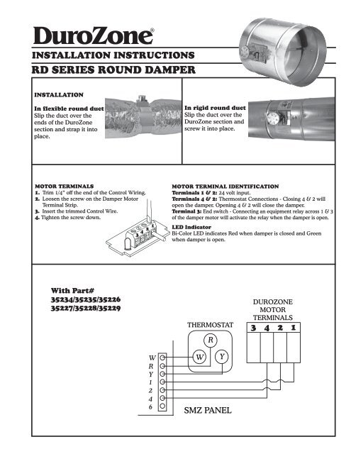
DuroZone ® INSTALLATION INSTRUCTIONS RD SERIES ROUND DAMPER INSTALLATION In flexible round duct Slip the duct over the ends of the DuroZone section and strap it into place. In rigid round duct Slip the duct over the DuroZone section and screw it into place. MOTOR TERMINALS 1. Trim 1/4” off the end of the Control Wiring. 2. Loosen the screw on the Damper Motor Terminal Strip. 3. Insert the trimmed Control Wire. 4. Tighten the screw down. MOTOR TERMINAL IDENTIFICATION Terminals 1 & 2: 24 volt input. Terminals 4 & 2: Thermostat Connections - Closing 4 & 2 will open the damper. Opening 4 & 2 will close the damper. Terminal 3: End switch - Connecting an equipment relay across 1 & 3 of the damper motor will activate the relay when the damper is open. LED Indicator Bi-Color LED indicates Red when damper is closed and Green when damper is open. With Part# 35234/35235/35226 35227/35228/35229 THERMOSTAT R DUROZONE MOTOR TERMINALS 3 4 2 1 W R Y 1 2 4 6 W Y SMZ PANEL
- Page 2 and 3: DuroZone ® INSTALLATION INSTRUCTIO
- Page 4: DuroZone ® INSTRUCCIONES DE INSTAL
<strong>Duro</strong>Zone<br />
®<br />
INSTALLATION INSTRUCTIONS<br />
RD SERIES ROUND DAMPER<br />
INSTALLATION<br />
In flexible round duct<br />
Slip the duct over the<br />
ends of the <strong>Duro</strong>Zone<br />
section and strap it into<br />
place.<br />
In rigid round duct<br />
Slip the duct over the<br />
<strong>Duro</strong>Zone section and<br />
screw it into place.<br />
MOTOR TERMINALS<br />
1. Trim 1/4” off the end of the Control Wiring.<br />
2. Loosen the screw on the <strong>Damper</strong> Motor<br />
Terminal Strip.<br />
3. Insert the trimmed Control Wire.<br />
4. Tighten the screw down.<br />
MOTOR TERMINAL IDENTIFICATION<br />
Terminals 1 & 2: 24 volt input.<br />
Terminals 4 & 2: Thermostat Connections - Closing 4 & 2 will<br />
open the damper. Opening 4 & 2 will close the damper.<br />
Terminal 3: End switch - Connecting an equipment relay across 1 & 3<br />
of the damper motor will activate the relay when the damper is open.<br />
LED Indicator<br />
Bi-Color LED indicates Red when damper is closed and Green<br />
when damper is open.<br />
With Part#<br />
35234/35235/35226<br />
35227/35228/35229<br />
THERMOSTAT<br />
R<br />
DUROZONE<br />
MOTOR<br />
TERMINALS<br />
3 4 2 1<br />
W<br />
R<br />
Y<br />
1<br />
2<br />
4<br />
6<br />
W<br />
Y<br />
SMZ PANEL
<strong>Duro</strong>Zone<br />
®<br />
INSTALLATION INSTRUCTIONS<br />
RD SERIES ROUND DAMPER<br />
ROOM THERMOSTAT<br />
R<br />
W<br />
Y<br />
PT40<br />
24 vac/40 VA<br />
TRANSFORMER<br />
Part# 35054<br />
∇<br />
*<br />
DUROZONE<br />
MOTOR TERMINALS<br />
3 4 2 1<br />
24 VAC between Terminal 1 and 3 when<br />
damper is open.<br />
End Switch - maximum load rating - 2<br />
amps. (usage optional)<br />
∇<br />
*<br />
Standard Heat/Cool thermostat can be used to control Air Flow by<br />
jumping terminal W and Y and then wiring to damper terminal #4.<br />
Wire R on the thermostat to damper terminal #2.<br />
TYPICAL WIRING<br />
FOR DUROZONE DAMPERS<br />
TO NON DUROZONE ZONING PANELS<br />
TRANSFORMER<br />
24 VAC<br />
When meter measures 24 VAC in<br />
reference to (M1) common, wire<br />
that transformer output to <strong>Duro</strong>Zone<br />
<strong>Damper</strong> Terminal #2.<br />
24 vac<br />
Meter<br />
Input<br />
24 VAC<br />
XXXXXX<br />
(M1) Common<br />
(M4) Open<br />
(M6) Close<br />
3<br />
4<br />
2<br />
1<br />
NOTE: If the Zone Panel has a terminal M2<br />
or 2, wire that panel terminal to damper<br />
terminal #2 instead of the power supply.<br />
<strong>Duro</strong> <strong>Dyne</strong> East • Bay Shore, NY 11706 • Phone: 631-249-9000 • Fax: 631-249-8346<br />
<strong>Duro</strong> <strong>Dyne</strong> Midwest • Fairfield, OH 45011 • Phone: 513-870-6000 • Fax: 513-870-6005<br />
<strong>Duro</strong> <strong>Dyne</strong> West • Fontana, CA 92337 • Phone: 562-926-1774 • Fax: 562-926-5778<br />
<strong>Duro</strong> <strong>Dyne</strong> Canada • Lachine • Quebec • Canada • Phone: 514-422-9760 • Fax: 514-636-0328<br />
©2014 <strong>Duro</strong> <strong>Dyne</strong> Corporation<br />
Printed in USA 10/2014<br />
BI035414<br />
www.durodyne.com<br />
Email: durodyne@durodyne.com<br />
ALL DUROZONE DAMPERS FEATURE:<br />
• 5 year limited warranty • Controlled bypass •<br />
Maintenance free operation • Quick install mounting<br />
clips (except <strong>Round</strong> <strong>Damper</strong>s) •100% factory testing •<br />
Screwless terminals • Custom dampers and special<br />
controls are available on request.
Se puede utilizar un termostato de calor-frío estándar para controlar el flujo de aire realizando un puente entre los<br />
terminales W e Y y luego conectándolo al terminal nº 4 de la compuerta de aire (damper). Conecte R del termostato al<br />
terminal nº 2 de la compuerta de aire (damper).<br />
TERMINALES DEL MOTOR<br />
DUROZONE<br />
<strong>Duro</strong>Zone<br />
®<br />
INSTRUCCIONES DE INSTALACIÓN<br />
COMPUERTA DE AIRE (DAMPER) REDONDA DE LA SERIE RD<br />
TERMOSTATO<br />
DE HABITACIÓN<br />
24 V de CA entre los terminales 1 y 3<br />
cuando la compuerta de aire (damper)<br />
está abierta.<br />
Interruptor de extremo: valor<br />
nominal de carga máximo de 2<br />
amperios (uso opcional).<br />
CABLEADO COMÚN PARA COMPUERTAS DE AIRE (DAMPERS) DUROZONE A PANE-<br />
LES DE CALDEO POR ZONAS QUE NO SEAN DUROZONE<br />
TRANSFORMADOR<br />
DE 24 V de CA<br />
Cuando el medidor mida 24 V de CA en<br />
referencia a (M1) común, conecte dicha<br />
salida del transformador al terminal 2 de la<br />
compuerta de aire (damper) <strong>Duro</strong>Zone.<br />
Medidor<br />
de 24 V<br />
de CA<br />
Entrada de<br />
24 V de CA<br />
(M1) Común<br />
(M4) Apertura<br />
(M6) Cierre<br />
NOTA: Si el panel de caldeo por zonas tiene un<br />
terminal M2 ó 2, conecte dicho terminal del panel<br />
al terminal nº 2 de la compuerta de aire (damper)<br />
en lugar de a la fuente de alimentación.<br />
División del Este de <strong>Duro</strong> <strong>Dyne</strong>, Bay Shore, NY (EE.UU.) 631-249-9000 Fax: 631-249-8346<br />
División del Centro de <strong>Duro</strong> <strong>Dyne</strong>, Fairfield, OH (EE.UU.) 513-870-6000 Fax: 513-870-6005<br />
División del Oeste de <strong>Duro</strong> <strong>Dyne</strong>, Fontana, CA (EE.UU.) 562-926-1774 Fax: 562-926-5778<br />
División de Canadá de <strong>Duro</strong> <strong>Dyne</strong>, Lachine, Quebec (Canadá) 514-422-9760 Fax: 514-636-0328<br />
©2014 <strong>Duro</strong> <strong>Dyne</strong> Corporation<br />
Impreso en EE.UU. 10/2014<br />
BI035414<br />
www.durodyne.com Correo electrónico: durodyne@durodyne.com<br />
TODAS LAS COMPUERTAS DE AIRE<br />
(DAMPERS) <strong>Duro</strong>Zone CUENTAN CON:<br />
• Garantía limitada por 5 años • Derivación controlada • Funcionamiento<br />
sin necesidad de mantenimiento • Abrazaderas de<br />
montaje de instalación rápida (excepto compuertas redondas) •<br />
Pruebas de fábrica al 100 % • Terminales sin tornillos • Compuertas<br />
de aire (dampers) y controles especiales personalizados disponibles<br />
bajo pedido.<br />
XXXXXX<br />
∇<br />
*<br />
3 4 2 1<br />
∇<br />
*<br />
TRANSFORMADOR<br />
DE 24 V de CA/DE 40 VA<br />
PT40<br />
Nº de pieza 35054<br />
R<br />
W<br />
Y<br />
3<br />
4<br />
2<br />
1
<strong>Duro</strong>Zone<br />
®<br />
INSTRUCCIONES DE INSTALACIÓN<br />
COMPUERTA DE AIRE (DAMPER) REDONDA DE LA SERIE RD<br />
INSTALACIÓN<br />
En conducto redondo<br />
flexible<br />
Deslice el conducto por<br />
los extremos de la sección<br />
<strong>Duro</strong>Zone y fíjelo en su<br />
sitio con la cinta.<br />
En conducto<br />
redondo rígido<br />
Deslice el conducto<br />
por la sección<br />
<strong>Duro</strong>Zone y<br />
atorníllelo en su sitio.<br />
TERMINALES DEL MOTOR<br />
1. Retire 1/4” del extremo del aislamiento del<br />
cable de control.<br />
2. Afloje el tornillo de la regleta de<br />
conexiones del motor de la<br />
compuerta de aire (damper).<br />
3. Introduzca el extremo pelado<br />
del cable de control.<br />
4. Apriete el tornillo.<br />
IDENTIFICACIÓN DE LOS TERMINALES DEL MOTOR<br />
Terminales 1 y 2: entrada de 24 voltios.<br />
Terminales 4 y 2: conexiones del termostato; si cierra 4 y 2, se<br />
abrirá la compuerta de aire (damper). Si abre 4 y 2, se cerrará la<br />
compuerta de aire (damper).<br />
Terminal 3: interruptor de extremo; si conecta un relé (relay) de<br />
equipo a 1 y 3 del motor de la compuerta de aire (damper), activará<br />
el relé (relay) cuando la compuerta de aire (damper) esté abierta.<br />
CON LOS NROS. DE PIEZA 35234/35235/35226<br />
35227/35228/35229<br />
TERMINALES<br />
DEL MOTOR<br />
DUROZONE<br />
TERMOSTATO<br />
3 4 2 1<br />
R<br />
W<br />
R<br />
Y<br />
1<br />
2<br />
4<br />
6<br />
W Y<br />
PANEL SMZ


