
Create successful ePaper yourself
Turn your PDF publications into a flip-book with our unique Google optimized e-Paper software.
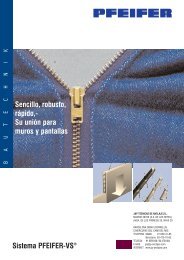
Por mejores soluciones...<br />
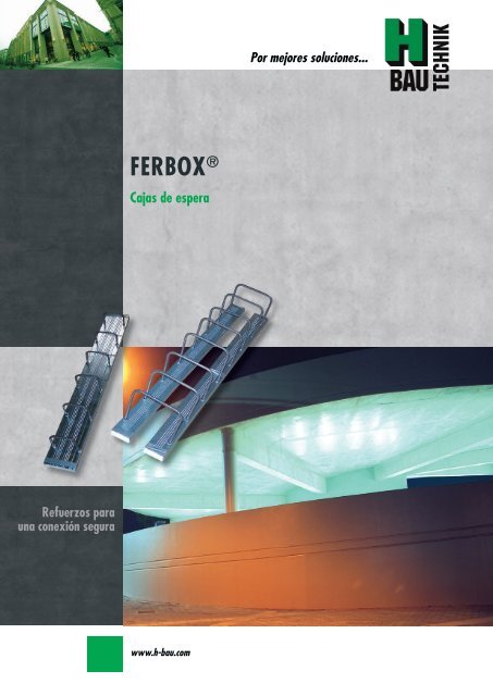
FERBOX ®<br />
Cajas <strong>de</strong> espera<br />
Refuerzos para<br />
una conexión segura<br />
www.h-bau.com
Contacto<br />
J&P Técnicas <strong>de</strong> <strong>Anclaje</strong> S.L<br />
Vila Caión 2 Bajo<br />
15100 Carballo<br />
A Coruña<br />
Telf: 627 44 82 94<br />
Fax: 981 75 51 03<br />
Web: www.jp-anclajes.com<br />
Mail: motero@jp-anclajes.com<br />
J&P Técnicas <strong>de</strong> <strong>Anclaje</strong> S.L<br />
C/ Cal Truco 50 - 60 Nave Schenker<br />
08820 El Prat <strong>de</strong> Llobregat<br />
Barcelona<br />
Telf: 93 374 10 30<br />
Fax: 93 374 14 59<br />
Web: www.jp-anclajes.com<br />
Mail: frieda@jp-anclajes.com<br />
J&P Técnicas <strong>de</strong> <strong>Anclaje</strong> S.L<br />
Avda. Pirineos 25 Nave 20<br />
28703 San Sebastián <strong>de</strong> los Reyes<br />
Madrid<br />
Telf: 91 659 31 85<br />
Fax: 91 659 31 39<br />
Web: www.jp-anclajes.com<br />
Mail: jp@jp-anclajes.com<br />
www.h-bau.com
FERBOX<br />
Por mejores soluciones...<br />
Contenido<br />
FERBOX<br />
Refuerzos para una conexión segura<br />
General 2-3<br />
Resumen <strong>de</strong> tipo y aplicaciones 4-5<br />
Elementos estándar 6-8<br />
<strong>Anclaje</strong>s y empalmes 9-10<br />
Tipos especiales 11<br />
Valores para el diseño <strong>de</strong> acuerdo con los ensayos tipo 13-17<br />
PENTABOX 18-19<br />
Oferta 20<br />
1<br />
Refuerzos para una conexión segura
Ferbox ®<br />
General<br />
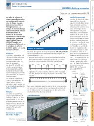
FERBOX ® - Cajas <strong>de</strong> espera para las mejores conexiones<br />
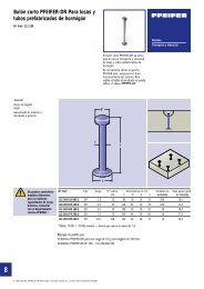
El producto<br />
La caja <strong>de</strong> espera FERBOX es un conector<br />
prefabricado con esperas que<br />
se <strong>de</strong>sdoblan para empalmes sencillos<br />
y seguros <strong>de</strong> elementos estructurales<br />
<strong>de</strong> hormigón <strong>de</strong> diferentes<br />
secciones.<br />
Se ha ensayado <strong>de</strong> acuerdo a la normativa<br />
DIN 1045-1 y se distingue por<br />
su variedad <strong>de</strong> tipos y dimensiones.<br />
La seguridad <strong>de</strong> la calidad <strong>de</strong>l FER-<br />
BOX se mantiene a través <strong>de</strong> inspecciones<br />
internas y externas.<br />
Ventajas<br />
Más rápido, una instalación más<br />
económica.<br />
Ensayado <strong>de</strong> acuerdo a la normativa<br />
DIN 1045-1<br />
Amplia gama <strong>de</strong> tipos.<br />
Caja protegida <strong>de</strong> chapa con tratamiento<br />
superficial rugoso que<br />
asegura una correcta adherencia.<br />
Cubierta hecha con chapa <strong>de</strong><br />
acero rígida zincada. La cubierta<br />
pue<strong>de</strong> retirase <strong>de</strong> forma fácil y rápida.<br />
Longitu<strong>de</strong>s y diámetros <strong>de</strong> empalme<br />
según DIN 1045-1 y el boletín<br />
DBV.<br />
Es posible fabricar la caja <strong>de</strong> empalme<br />
con curvatura.<br />
Aplicación<br />
Las cajas <strong>de</strong> espera FERBOX permiten<br />
realizar uniones estructurales <strong>de</strong><br />
hormigón armado hormigonando en<br />
diferentes fases.<br />
Se pue<strong>de</strong>n unir pantallas, losas, ménsulas<br />
o escaleras <strong>de</strong> forma fiable a<br />
posteriori..<br />
2<br />
www.h-bau.com
Ferbox ®<br />
General<br />
Por mejores soluciones...<br />
Información técnica.<br />
No requiere ensayos o certificados<br />
adicionales ya que se ha ensayado<br />
según la DIN 1045-1 y el<br />
boletín DBV “Desdoblado <strong>de</strong> armaduras<br />
<strong>de</strong> refuerzo y requerimientos<br />
para las cajas<br />
protectoras”<br />
Armaduras <strong>de</strong> refuerzo estándar<br />
Ø 8/10/12<br />
Verwahrkasten<br />
Bewehrungsstäbe<br />
Ø 8/10/12<br />
Armaduras <strong>de</strong> refuerzo especiales<br />
Ø 14/16<br />
Las alas laterales cortas garantizan<br />
un completo recubrimiento <strong>de</strong>l<br />
perfil con el hormigón.<br />
c<br />
Beton<strong>de</strong>ckung<br />
einhalten!<br />
La capa <strong>de</strong> recubrimiento “c” <strong>de</strong><br />
hormigón <strong>de</strong>be mantenerse.<br />
Longitud estándar: 1,25m. Otras<br />
longitu<strong>de</strong>s a petición.<br />
Instrucciones <strong>de</strong> instalación<br />
La caja <strong>de</strong> empalme Ferbox <strong>de</strong>be<br />
fijarse fuertemente y con una colocación<br />
precisa al encofrado.<br />
- Clavándolo firmemente al encofrado<br />
<strong>de</strong> ma<strong>de</strong>ra.<br />
- Clavándolo al encofrado metálico<br />
-Soldándolo a las armaduras existentes.<br />
Tras la primera fase <strong>de</strong> hormigonado,<br />
la chapa protectora se retira<br />
mediante martillo.<br />
Se retiran las láminas <strong>de</strong> poliestireno<br />
<strong>de</strong> los extremos.<br />
Posteriormente, se en<strong>de</strong>rezan las<br />
barras con un tubo <strong>de</strong> <strong>de</strong>sdoblado<br />
cuyo diámetro interior sea ligeramente<br />
superior al <strong>de</strong> la barra (<strong>de</strong><br />
acuerdo con el boletín DBV). Se<br />
encaja el tubo hasta la curvatura<br />
original y se trae la barra a su posición<br />
correspondiente mediante<br />
esfuerzos escalonados, evitando<br />
alternancias <strong>de</strong> doblado – <strong>de</strong>sdoblado.<br />
En ningún caso <strong>de</strong>be utilizarse <strong>de</strong>sencofrante<br />
en la zona <strong>de</strong> junta<br />
con el perfil embebido.<br />
Retire cualquier mancha o posible<br />
contaminante <strong>de</strong>l hormigón.<br />
Coloque el armado <strong>de</strong> la segunda<br />
fase <strong>de</strong> hormigonado y hormigone.<br />
Montaje al encofrado circular<br />
Utilizando un ángulo doble las alas<br />
laterales <strong>de</strong> la caja protectora y haga<br />
un corte en ambos lados a distancias<br />
regulares <strong>de</strong>terminadas según el<br />
radio <strong>de</strong> curvatura <strong>de</strong>l encofrado.<br />
Esto permite a la caja <strong>de</strong> espera adaptarse<br />
a la forma circular <strong>de</strong>l encofrado.<br />
Importante:<br />
Asegúrese <strong>de</strong> que las esperas <strong>de</strong> refuerzo<br />
no están dañadas!.<br />
3<br />
Refuerzos para una conexión segura
Ferbox ®<br />
Resumen <strong>de</strong> tipo y aplicaciones<br />
FERBOX ® tipo B<br />
Tipo especial A0<br />
Tipo estándar<br />
Conexión <strong>de</strong> espera doble, por ejemplo para conectar muro <strong>de</strong> hormigón y<br />
techo.<br />
FERBOX ® tipo A1<br />
Tipo especial<br />
Conexión <strong>de</strong> espera doble, por ejemplo para conectar una ménsula a un muro<br />
<strong>de</strong> hormigón.<br />
FERBOX ® tipo A2<br />
Tipo especial<br />
Conexión <strong>de</strong> espera doble, por ejemplo para conectar una ménsula a un muro<br />
<strong>de</strong> hormigón.<br />
FERBOX ® tipo A2V<br />
Tipo especial<br />
Conexión <strong>de</strong> espera doble, por ejemplo para conectar una ménsula a un muro<br />
<strong>de</strong> hormigón que requiera mayor longitud <strong>de</strong> espera.<br />
FERBOX ® tipo A3<br />
Tipo especial<br />
Conexión <strong>de</strong> espera doble, por ejemplo para conectar una ménsula a un muro<br />
<strong>de</strong> hormigón.<br />
FERBOX ® tipo R3<br />
Tipo especial<br />
Conexión <strong>de</strong> espera doble, por ejemplo para conectar una ménsula a un muro<br />
<strong>de</strong> hormigón.<br />
FERBOX ® tipo D<br />
Tipo estándar<br />
Conexión <strong>de</strong> espera doble, por ejemplo para conectar muro <strong>de</strong> hormigón <strong>de</strong><br />
espesor ≥ 270mm a otro muro <strong>de</strong> hormigón.<br />
4 www.h-bau.com
Ferbox ®<br />
Resumen <strong>de</strong> tipo y aplicaciones<br />
Por mejores soluciones...<br />
FERBOX ® tipo E<br />
Tipo especial S5<br />
Tipo estándar<br />
Conexión <strong>de</strong> espera simple, por ejemplo para conectar muro <strong>de</strong> hormigón <strong>de</strong><br />
espesor ≥ 80 mm a otro muro o pilar <strong>de</strong> hormigón.<br />
FERBOX ® tipo S1<br />
Tipo especial<br />
Conexión <strong>de</strong> espera simple, por ejemplo para conectar muro <strong>de</strong> hormigón a<br />
otro muro o pilar <strong>de</strong> hormigón.<br />
FERBOX ® tipo S2<br />
Tipo especial<br />
Conexión <strong>de</strong> espera simple, por ejemplo para conectar muro <strong>de</strong> hormigón a<br />
otro muro o pilar <strong>de</strong> hormigón.<br />
FERBOX ® tipo S3<br />
Tipo especial<br />
Conexión <strong>de</strong> espera doble, por ejemplo para conectar un muro <strong>de</strong> hormigón<br />
con el techo.<br />
FERBOX ® tipo S4<br />
Tipo especial<br />
Conexión <strong>de</strong> espera simple <strong>de</strong> conexión en ambos lados, por ejemplo para conectar<br />
muro con muro <strong>de</strong> hormigón.<br />
FERBOX ® tipo F<br />
Tipo estándar<br />
Conexión <strong>de</strong> espera doble, por ejemplo para conectar pare<strong>de</strong>s prefabricadas<br />
<strong>de</strong> hormigón.<br />
FERBOX ® tipo S6<br />
Tipo especial<br />
Conexión <strong>de</strong> espera doble <strong>de</strong> conexión en ambos lados, por ejemplo para<br />
conectar muro con muro <strong>de</strong> hormigón.<br />
5<br />
Refuerzos para una conexión segura
Ferbox ®<br />
Elementos estándar<br />
FERBOX ® tipo B - Conexión <strong>de</strong> espera doble<br />
Armadura <strong>de</strong> refuerzo <strong>de</strong> acero BST 500WR<br />
Diámetro <strong>de</strong> doblado <strong>de</strong> bloqueo d BR = 6 x d s <strong>de</strong> acuerdo<br />
con la DIN 1045-1<br />
Fabricado <strong>de</strong> acuerdo con el boletín DBV<br />
Longitud estándar 1,25m<br />
Tipo<br />
B<br />
Ancho <strong>de</strong><br />
estribo b<br />
[mm]<br />
Long. <strong>Anclaje</strong><br />
lü / Ø<br />
[mm]<br />
Dist. Entre<br />
barras<br />
e [mm]<br />
Altura <strong>de</strong><br />
estribo<br />
h [mm]<br />
Ancho <strong>de</strong><br />
perfil<br />
d [mm]<br />
Profundidad<br />
<strong>de</strong> perfil<br />
H [mm]<br />
Profundidad<br />
<strong>de</strong> perfil<br />
+ cubierta<br />
F [mm]<br />
Espesor <strong>de</strong><br />
muro o elemento<br />
B1 [mm]<br />
Espesor <strong>de</strong><br />
muro o elemento<br />
B2 [mm]<br />
B 9- 8-15<br />
B 9- 8-20<br />
B 9-10-15<br />
B 9-10-20<br />
B 9-12-15<br />
B 9-12-20<br />
90<br />
320/ 8<br />
320/ 8<br />
390/10<br />
390/10<br />
460/12<br />
440/12<br />
150<br />
200<br />
150<br />
200<br />
150<br />
200<br />
170 115 21<br />
30<br />
30<br />
30<br />
30<br />
40<br />
40<br />
≥ 200 140-180<br />
B 12- 8-15<br />
B 12- 8-20<br />
B 12-10-15<br />
B 12-10-20<br />
B 12-12-15<br />
B 12-12-20<br />
120<br />
320/ 8<br />
320/ 8<br />
390/10<br />
390/10<br />
460/12<br />
460/12<br />
150<br />
200<br />
150<br />
200<br />
150<br />
200<br />
170 145 21<br />
30<br />
30<br />
30<br />
30<br />
40<br />
40<br />
≥ 200 170-210<br />
B 14- 8-15<br />
B 14- 8-20<br />
B 14-10-15<br />
B 14-10-20<br />
B 14-12-15<br />
B 14-12-20<br />
140<br />
320/ 8<br />
320/ 8<br />
390/10<br />
390/10<br />
460/12<br />
460/12<br />
150<br />
200<br />
150<br />
200<br />
150<br />
200<br />
170 165 21<br />
30<br />
30<br />
30<br />
30<br />
40<br />
40<br />
≥ 200 190-230<br />
B 16- 8-15<br />
B 16- 8-20<br />
B 16-10-15<br />
B 16-10-20<br />
B 16-12-15<br />
B 16-12-20<br />
160<br />
320/ 8<br />
320/ 8<br />
390/10<br />
390/10<br />
460/12<br />
460/12<br />
150<br />
200<br />
150<br />
200<br />
150<br />
200<br />
170 185 21<br />
30<br />
30<br />
30<br />
30<br />
40<br />
40<br />
≥ 200 210-250<br />
B 18- 8-15<br />
B 18- 8-20<br />
B 18-10-15<br />
B 18-10-20<br />
B 18-12-15<br />
B 18-12-20<br />
180<br />
320/ 8<br />
320/ 8<br />
390/10<br />
390/10<br />
460/12<br />
460/12<br />
150<br />
200<br />
150<br />
200<br />
150<br />
200<br />
170 205 21<br />
30<br />
30<br />
30<br />
30<br />
40<br />
40<br />
≥ 200 230-270<br />
B 20- 8-15<br />
B 20- 8-20<br />
B 20-10-15<br />
B 20-10-20<br />
B 20-12-15<br />
B 20-12-20<br />
200<br />
320/ 8<br />
320/ 8<br />
390/10<br />
390/10<br />
460/12<br />
460/12<br />
150<br />
200<br />
150<br />
200<br />
150<br />
200<br />
170 225 21<br />
30<br />
30<br />
30<br />
30<br />
40<br />
40<br />
≥ 200 250-290<br />
6<br />
www.h-bau.com
Ferbox ®<br />
Elementos estándar<br />
Por mejores soluciones...<br />
FERBOX ® tipo E - Conexión <strong>de</strong> espera simple<br />
Armadura <strong>de</strong> refuerzo <strong>de</strong> acero BST 500WR<br />
Diámetro <strong>de</strong> doblado <strong>de</strong> bloqueo d BR = 6 x d s <strong>de</strong> acuerdo<br />
con la DIN 1045-1<br />
Fabricado <strong>de</strong> acuerdo con el boletín DBV<br />
Longitud estándar 1,25m<br />
Tipo<br />
E<br />
Ancho <strong>de</strong><br />
estribo b<br />
[mm]<br />
Long. <strong>Anclaje</strong><br />
lü / Ø<br />
[mm]<br />
Dist. Entre<br />
barras<br />
e [mm]<br />
Altura <strong>de</strong><br />
estribo<br />
h [mm]<br />
Ancho <strong>de</strong><br />
perfil<br />
d [mm]<br />
Profundidad<br />
<strong>de</strong> perfil<br />
H [mm]<br />
Profundidad<br />
<strong>de</strong> perfil<br />
+ cubierta<br />
F [mm]<br />
Espesor <strong>de</strong><br />
muro o elemento<br />
B1 [mm]<br />
Espesor <strong>de</strong><br />
muro o elemento<br />
B2 [mm]<br />
E 8-10<br />
E 8-15<br />
E 8-20<br />
E 8-25<br />
72 320/ 8<br />
150<br />
200<br />
250<br />
170 55 21 30 ≥ 200 ≥ 80<br />
E 10-10<br />
E 10-15<br />
E 10-20<br />
E 10-25<br />
90 390/10<br />
150<br />
200<br />
250<br />
170 55 21 30 ≥ 200 ≥ 80<br />
E 12-10<br />
E 12-15<br />
E 12-20<br />
E 12-25<br />
110 460/12<br />
150<br />
200<br />
250<br />
170 85 21 40 ≥ 200 ≥ 110<br />
7<br />
Refuerzos para una conexión segura
Ferbox ®<br />
Elementos estándar<br />
FERBOX ® tipo F - Conexión <strong>de</strong> espera doble para pare<strong>de</strong>s prefabricadas<br />
Armadura <strong>de</strong> refuerzo <strong>de</strong> acero BST 500WR<br />
Fabricado <strong>de</strong> acuerdo con el boletín DBV<br />
Longitud estándar 1,25m<br />
Tipo<br />
F<br />
Ancho <strong>de</strong><br />
estribo b [mm]<br />
Long. <strong>Anclaje</strong><br />
lü / Ø<br />
[mm]<br />
Dist. Entre barras<br />
e [mm]<br />
Altura <strong>de</strong><br />
estribo<br />
h [mm]<br />
Ancho <strong>de</strong> perfil<br />
d [mm]<br />
Profundidad <strong>de</strong><br />
perfil<br />
H [mm]<br />
Profundidad <strong>de</strong><br />
perfil<br />
+ cubierta<br />
F [mm]<br />
Espesor <strong>de</strong><br />
muro o elemento<br />
B2 [mm]<br />
F 8-15<br />
F 8-20<br />
F 8-25<br />
60 83/ 8<br />
150<br />
200<br />
250<br />
330 85 21 30 110-180<br />
F 10-15<br />
F 10-20<br />
F 10-25<br />
60 83/10<br />
150<br />
200<br />
250<br />
400 85 21 30 110-180<br />
FERBOX ® tipo D - Conexión <strong>de</strong> espera doble<br />
Armadura <strong>de</strong> refuerzo <strong>de</strong> acero BST 500WR<br />
Diámetro <strong>de</strong> doblado <strong>de</strong> bloqueo d BR = 6 x d s <strong>de</strong> acuerdo<br />
con la DIN 1045-1<br />
Fabricado <strong>de</strong> acuerdo con el boletín DBV<br />
Longitud estándar 1,25m<br />
Tipo<br />
D<br />
Ancho <strong>de</strong><br />
estribo b<br />
[mm]<br />
Long. <strong>Anclaje</strong><br />
lü / Ø<br />
[mm]<br />
Dist. Entre<br />
barras<br />
e [mm]<br />
Altura <strong>de</strong><br />
estribo<br />
h [mm]<br />
Ancho <strong>de</strong><br />
perfil<br />
d [mm]<br />
Profundidad<br />
<strong>de</strong> perfil<br />
H [mm]<br />
Profundidad<br />
<strong>de</strong> perfil<br />
+ cubierta<br />
F [mm]<br />
Espesor <strong>de</strong><br />
muro o elemento<br />
B1 [mm]<br />
Espesor <strong>de</strong><br />
muro o elemento<br />
B2 [mm]<br />
D 24- 8-15<br />
D 24- 8-20<br />
240 320/ 8<br />
150<br />
200<br />
170 265 21 30 ≥ 200 290-360<br />
D 24-10-15<br />
D 24-10-20<br />
240 390/ 10<br />
150<br />
200<br />
170 265 21 30 ≥ 200 290-360<br />
D 24-12-15<br />
D 24-12-20<br />
240 460/ 12<br />
150<br />
200<br />
170 265 21 40 ≥ 200 290-360<br />
8 www.h-bau.com
Ferbox ®<br />
<strong>Anclaje</strong>s y empalmes según DIN 1045-1<br />
Por mejores soluciones...<br />
Longitud <strong>de</strong> empalme l ü<br />
(3) Según la DIN 1045-1, 12.3.2 (2), la armadura <strong>de</strong> refuerzo en la zona don<strong>de</strong> se <strong>de</strong>sdoblan las esperas y bajo<br />
efectos predominantemente estacionarios al límite <strong>de</strong> la capacidad <strong>de</strong> carga, sólo <strong>de</strong>ben utilizarse al 80% <strong>de</strong> los<br />
valores permisibles según la curva <strong>de</strong> tensión <strong>de</strong>formación <strong>de</strong>l acero <strong>de</strong> las armaduras <strong>de</strong> refuerzo según la DIN<br />
1045-1, Fig.27. El tamaño básico para esta longitud <strong>de</strong> empalme lb para las esperas, <strong>de</strong> acuerdo con la DIN<br />
1045-1, 12.6.2, ecuación 140, <strong>de</strong>be <strong>de</strong>terminarse utilizando el valor más reducido para la tensión <strong>de</strong>l acero<br />
f yd,red = 0,8 ⋅ f yk / γ s .<br />
Fuente: Ficha técnica DVB (DVB = Sociedad Alemana <strong>de</strong>l hormigón y la tecnología <strong>de</strong> la construcción) “esperas <strong>de</strong>sdobladas”, sección 3.1vvvvb<br />
A<br />
l b,net = α a ⋅ s,erf<br />
⋅ l b<br />
l<br />
A b,net Longitud <strong>de</strong> anclaje <strong>de</strong> acuerdo con la ecuación 141 (DIN 1045-1)<br />
s,vorh<br />
l b,net 80% = l b,net ⋅ 0,8<br />
l b,net 80% Longitud <strong>de</strong> anclaje al 80% <strong>de</strong> la carga<br />
l s = l b,net 80% ⋅α 1<br />
l s<br />
longitud <strong>de</strong> solape<br />
l ü<br />
Longitud estándar <strong>de</strong> solape <strong>de</strong> acuerdo con ensayos tipo.<br />
Hormigón<br />
Longitud básica <strong>de</strong> anclaje l b [cm]<br />
Condición<br />
<strong>de</strong>l empalme<br />
Diámetro <strong>de</strong> la barra d s [mm]<br />
8 10 12<br />
C20/25 gut 37 47 56<br />
C25/30 gut 32 40 48<br />
C30/37 gut 29 36 43<br />
α a = 1,0 (coeficiente para el diseño <strong>de</strong> la barra)<br />
A s,erf<br />
A s,vorh<br />
= 1,0 (ratio <strong>de</strong> las zonas <strong>de</strong> sección en cruz)<br />
α 1 = 1,0 (si e ≥ 10 d s y la distancia a bor<strong>de</strong> ≥ 5 d s )<br />
α 1 = 1,4 (si e ≤ 10 d s y la distancia a bor<strong>de</strong> ≤ 5 d s )<br />
Ø d s / e<br />
Porcentaje <strong>de</strong> refuerzo [cm²/m] Longitud <strong>de</strong> solape [mm] para C20/25<br />
100 % 80 % l s 100% l s 80% l ü estándar<br />
h [mm]<br />
Ø 8 / 25 2,01 1,61<br />
Ø 8 / 20 2,51 2,01<br />
Ø 8 / 15 3,35 2,68<br />
378 302 320 170<br />
Ø 8 / 10 5,03 4,02<br />
Ø 10 / 25 3,14 2,51<br />
Ø 10 / 20 3,93 3,14<br />
Ø 10 / 15 5,24 4,19<br />
473 378 390 170<br />
Ø 10 / 10 7,85 6,28<br />
Ø 12 / 25 4,52 3,62<br />
Ø 12 / 20 5,65 4,52<br />
567 454<br />
Ø 12 / 15 7,54 6,03<br />
460 170<br />
Ø 12 / 10 11,31 9,05 794* 635*<br />
* Calculado con α 1 = 1,4<br />
9<br />
Refuerzos para una conexión segura
Ferbox ®<br />
Longitu<strong>de</strong>s máximas <strong>de</strong> solape para tipos especiales<br />
Caja<br />
[mm]<br />
Barra Ø<br />
[mm]<br />
Espaciamiento<br />
[mm]<br />
max. l ü [mm] para tipos especiales<br />
S1, S2, S4,<br />
S5 (E), D<br />
S3, S6,<br />
A0 (B), R3<br />
A1, A2, A2V,<br />
A3<br />
Caja<br />
[mm]<br />
Barra Ø<br />
[mm]<br />
Espaciamiento<br />
[mm]<br />
max. l ü [mm] para tipos especiales<br />
S1, S2, S4,<br />
S5 (E), D<br />
S3, S6,<br />
A0 (B), R3<br />
A1, A2, A2V,<br />
A3<br />
50<br />
8<br />
10<br />
100 320 - -<br />
150 410 - -<br />
200 550 - -<br />
100 280 - -<br />
150 400 - -<br />
200 500 - -<br />
165<br />
8<br />
10<br />
100 - 600 90 / 335*<br />
150 - 600 140 / 430*<br />
200 - 600 190 / 250*<br />
100 - 460 90 / 220*<br />
150 - 600 140 / 280*<br />
200 - 600 190 / 420*<br />
8<br />
100 - - 90<br />
150 - - 140<br />
200 - - 190<br />
12<br />
100 - 430 100 / 140*<br />
150 - 600 170 / 230*<br />
200 - 600 220 / 320*<br />
85<br />
10<br />
100 - - -<br />
150 - - -<br />
200 - - -<br />
8<br />
100 - 600 90 / 435*<br />
150 - 600 140 / 550*<br />
200 - 600 190 / 580*<br />
12<br />
100 520 - -<br />
150 600 - -<br />
200 600 - -<br />
185<br />
10<br />
100 - 550 90 / 320*<br />
150 - 600 140 / 400*<br />
200 - 600 190 / 580*<br />
8<br />
100 - 340 90 / 165*<br />
150 - 510 140 / 215*<br />
200 - 600 190 / 270*<br />
12<br />
100 - 480 100 / 220*<br />
150 - 600 170 / 330*<br />
200 - 600 220 / 480*<br />
115<br />
10<br />
100 - 250 90<br />
150 - 390 140<br />
200 - 460 190<br />
8<br />
100 - 600 90 / 515*<br />
150 - 600 140 / 580*<br />
200 - 600 190 / 580*<br />
12<br />
100 - - 75<br />
150 - 430 120<br />
200 - 460 170<br />
205<br />
10<br />
100 - 600 90 / 515*<br />
150 - 600 140 / 580*<br />
200 - 600 190 / 580*<br />
8<br />
100 - 500 90 / 215*<br />
150 - 600 140 / 290*<br />
200 - 600 190 / 380*<br />
12<br />
100 - 550 100 / 300*<br />
150 - 600 170 / 450*<br />
200 - 600 220 / 580*<br />
145<br />
10<br />
100 - 380 100<br />
150 - 530 170<br />
200 - 600 220<br />
8<br />
100 - 600 90 / 580*<br />
150 - 600 140 / 580*<br />
200 - 600 190 / 580*<br />
12<br />
100 - 400 90 / 335*<br />
150 - 550 140 / 430*<br />
200 - 600 190 / 420*<br />
225<br />
10<br />
100 - 600 90 / 520*<br />
150 - 600 140 / 600*<br />
200 - 600 190 / 600*<br />
max. l ü para distancia e= 250 mm bajo pedido<br />
* Para esperas <strong>de</strong> cajas <strong>de</strong> empalme curvas tipo A1,A2, A2V A3<br />
12<br />
100 - 600 100 / 380*<br />
150 - 600 170 / 550*<br />
200 - 600 220 / 580*<br />
Configuración <strong>de</strong> esperas y longitud máxima <strong>de</strong> solape max. l ü<br />
Tapón <strong>de</strong> corcho Tapón <strong>de</strong> corcho<br />
Tapón <strong>de</strong> corcho Tapón <strong>de</strong> corcho<br />
tipo B, E, S1, S2, S3, S4,<br />
S5, S6, A0, R3, D<br />
tipo F, A1, A2, A2V, A3<br />
curvado normal<br />
Tapón <strong>de</strong> corcho<br />
Tapón <strong>de</strong> corcho<br />
tipo A1, A2, A2V, A3<br />
curvado cónico<br />
* Para esperas <strong>de</strong> cajas <strong>de</strong> empalme curvas tipo A1,A2, A2V A3<br />
10 www.h-bau.com
Ferbox ®<br />
Tipos especiales<br />
Por mejores soluciones...<br />
tipo S1<br />
tipo S2<br />
tipo S3<br />
tipo S4<br />
tipo S5<br />
tipo S6<br />
tipo A0<br />
tipo A1<br />
tipo A2<br />
tipo A2V<br />
tipo A3<br />
tipo R3<br />
tipo D<br />
Solicitud <strong>de</strong> presupuesto / Pedido<br />
Proyecto:<br />
Pos.<br />
tipo<br />
Dimensiones [mm]<br />
b h lü * v<br />
acero<br />
Ø [mm]<br />
Dist. Entre<br />
barras<br />
e [mm]<br />
Longitud caja<br />
L [mm]<br />
Cantidad<br />
ml [m]<br />
Notas<br />
*A tener en cuenta las longitu<strong>de</strong>s máximas <strong>de</strong> empalme dadas en la tabla 14<br />
11<br />
Refuerzos para una conexión segura
Ferbox ®<br />
Pautas para el cálculo según el boletín DBV<br />
Esfuerzo cortante paralelo a la junta <strong>de</strong> hormigonado:<br />
a<br />
b<br />
Porcentaje <strong>de</strong> área <strong>de</strong> contacto: [R1] eq. 84 sin<br />
1/3<br />
v Rd,cj = 0,042 1 ct f ck b<br />
Cortante con armaduras <strong>de</strong> empalme: [R1] eq. 85<br />
v Rd,sy = a s f yd (cot + cot ) sin – Nd b<br />
Nd<br />
Cortante para los puntales: análogo [R1] eq. 78<br />
v Rd,max = 0,30 b w 0,75 f cd (cot + cot ) / (1 + cot² )<br />
v Ed<br />
b<br />
v Ed<br />
a 2<br />
a 1<br />
b<br />
a 1 5 cm a 1 5 cm<br />
a 2 5 cm mit Oberflächenbeschaffenheit<br />
nach<br />
DIN 1045-1, Tab. 13<br />
a 1> 5cm se pue<strong>de</strong> añadir a b al igual que a 2, sin embargo<br />
hay que consi<strong>de</strong>rar para b la menor calidad superficial <strong>de</strong><br />
la caja o <strong>de</strong> la junta <strong>de</strong> hormigonado.<br />
Alternativamente, el espesor <strong>de</strong> las superficies <strong>de</strong> la junta<br />
<strong>de</strong> hormigonado o <strong>de</strong> la caja <strong>de</strong> empalme pue<strong>de</strong> ser<br />
consi<strong>de</strong>rado junto con la calidad superficial para b.<br />
a 1<br />
Limitación <strong>de</strong> la curvatura <strong>de</strong>l puntal (R1)<br />
eq.86 sin esfuerzo longitudinal:<br />
1,2<br />
1,0 cot<br />
3,0<br />
v<br />
Rd, ct<br />
1<br />
v<br />
Ed<br />
Superficie <strong>de</strong> junta ct [R1], Tab. 13<br />
verzahnt Dentada<br />
2,4 1,0<br />
rau Sin tratar 2,0 a) 0,7<br />
a) für Nd > 0 gilt:<br />
glatt Lisa<br />
1,4 a) 0,6 ct = 0<br />
sehr Muy lisa glatt 0 0,5<br />
En losas con zuncho perimetral, la verificación <strong>de</strong> la junta<br />
<strong>de</strong>be llevarse a cabo utilizando ct y , en este caso el<br />
esfuerzo cortante VRd,ct<br />
para juntas no <strong>de</strong>ntadas no <strong>de</strong>be<br />
ser mayor <strong>de</strong> b . 0,15 N/mm2 ((R1) 10.3.6(7))<br />
c<br />
V Ed<br />
d<br />
F s<br />
a 1 a 1<br />
Esfuerzo cortante vertical a la junta <strong>de</strong> hormigonado:<br />
Esfuerzo cortante asumible sin armado:<br />
[R1] eq. 70 con reducción por coeficiente <strong>de</strong> rugosidad<br />
V Rd,ct = ( ct / 2,4) [0,10 1 (100 l f ck) 1/3 – 0,12 cd]<br />
b w d<br />
d<br />
d<br />
F c<br />
con 1 200 / d( mm ) 2,<br />
0<br />
y con <strong>de</strong> acuerdo a (R1), tabla 13<br />
ct<br />
a 1<br />
Esfuerzo cortante sostenible con armado:<br />
[R1] eq. 75<br />
V Rd,sy = a sw f yd z cot<br />
con a sw = A sw / s w y z 0,9 d d o z d – 2 c nom,l<br />
Muro – forjado<br />
forjado – forjado<br />
Esfuerzo máximo sostenible con armado:<br />
(R1) eq.76 (para refuerzos en los estribos) en el área<br />
<strong>de</strong> <strong>de</strong>sdoblado límite 60%<br />
V Rd,max = 0,30 b w z c f cd / (cot + tan )<br />
Bild 8<br />
Bild 6<br />
con c = 0,75<br />
e<br />
V Ed<br />
f<br />
1<br />
d<br />
a 2<br />
1,2<br />
1,0 cot<br />
Bemessung im Grenzzustand <strong>de</strong>r Tragfähigkeit - Querschnittswerte 1<br />
d<br />
a 1<br />
Bemessung im Grenzzustand a2<br />
<strong>de</strong>r 5 cm Tragfähigkeit con propieda<strong>de</strong>s - Querschnittswerte<br />
<strong>de</strong> superficie según<br />
DIN 1045-1, tabla 13<br />
Limitación <strong>de</strong> la curvatura <strong>de</strong> la espera:<br />
[R1] eq. 73, pero con limitación <strong>de</strong> 45° en el área<br />
l e = 0,5 cot d en ambos lados <strong>de</strong> la junta:<br />
1,4 / f<br />
v<br />
Rd ,c<br />
con [R1] eq. 74<br />
V Rd,c = 0,10 ct 1 f ck<br />
1/3<br />
con ct según [R1], Tab. 13<br />
cd<br />
/ v<br />
Ed<br />
cd<br />
3,0<br />
(1 + 1,2 cd / f cd) b w z<br />
Límite <strong>de</strong> escalón <strong>de</strong> hormigonado, [R1] DIN 1045-1<br />
Fuente:<br />
Boletín DBV “armaduras <strong>de</strong>sdobladas <strong>de</strong> acero y requerimientos <strong>de</strong> las cajas <strong>de</strong> protección”<br />
Edición <strong>de</strong> Marzo 2003 – Actualizada a febrero 2005<br />
Fig. 8: dimensionado <strong>de</strong> la capacidad <strong>de</strong> carga / valores <strong>de</strong> la sección en el límite<br />
12 www.h-bau.com
Ferbox ®<br />
Valores para el diseño <strong>de</strong> acuerdo con los ensayos tipo<br />
Por mejores soluciones...<br />
Esfuerzo cortante paralelo a la junta - caso a<br />
Hipótesis:<br />
Capacidad <strong>de</strong> carga <strong>de</strong> la junta en el caso a, boletín DBV <strong>de</strong> armaduras <strong>de</strong>sdobladas.<br />
a 1 ≤ 5cm σ cd = σ Nd = 0<br />
h<br />
lü<br />
Límite <strong>de</strong> Betonierabschnittsgrenze<br />
la junta <strong>de</strong> hormigonado<br />
V Ed<br />
a1 b a1<br />
max v Ed [kN/m]<br />
C20/25 B6 B9 B12 B14 B16 B18 B20<br />
Ø 8/25 48,5 65,6 82,7 92,9 96,1 99,3 102,5<br />
Ø 8/20 48,5 65,6 82,7 94,1 105,5 116,0 119,2<br />
Ø 8/15 48,5 65,6 82,7 94,1 105,5 116,9 128,3<br />
Ø 8/10 65,6 82,7 94,1 105,5 116,9 128,3<br />
Ø 10/25 48,5 65,6 82,7 94,1 105,5 116,0 119,2<br />
Ø 10/20 48,5 65,6 82,7 94,1 105,5 116,9 128,3<br />
Ø 10/15 48,5 65,6 82,7 94,1 105,5 116,9 128,3<br />
Ø 10/10 65,6 82,7 94,1 105,5 116,9 128,3<br />
Ø 12/25 65,6 82,7 94,1 105,5 116,9 128,3<br />
Ø 12/20 65,6 82,7 94,1 105,5 116,9 128,3<br />
Ø 12/15 65,6 82,7 94,1 105,5 116,9 128,3<br />
Ø 12/10 65,6 82,7 94,1 105,5 116,9 128,3<br />
C25/30 B6 B9 B12 B14 B16 B18 B20<br />
Ø 8/25 52,2 70,6 89,0 101,3 110,0 113,4 116,9<br />
Ø 8/20 52,2 70,6 89,0 101,3 113,6 125,9 136,4<br />
Ø 8/15 52,2 70,6 89,0 101,3 113,6 125,9 138,2<br />
Ø 8/10 70,6 89,0 101,3 113,6 125,9 138,2<br />
Ø 10/25 52,2 70,6 89,0 101,3 113,6 125,9 136,4<br />
Ø 10/20 52,2 70,6 89,0 101,3 113,6 125,9 138,2<br />
Ø 10/15 52,2 70,6 89,0 101,3 113,6 125,9 138,2<br />
Ø 10/10 70,6 89,0 101,3 113,6 125,9 138,2<br />
Ø 12/25 70,6 89,0 101,3 113,6 125,9 138,2<br />
Ø 12/20 70,6 89,0 101,3 113,6 125,9 138,2<br />
Ø 12/15 70,6 89,0 101,3 113,6 125,9 138,2<br />
Ø 12/10 70,6 89,0 101,3 113,6 125,9 138,2<br />
C30/37 B6 B9 B12 B14 B16 B18 B20<br />
Ø 8/25 55,5 75,0 94,6 107,7 120,7 124,3 128,0<br />
Ø 8/20 55,5 75,0 94,6 107,7 120,7 133,8 146,8<br />
Ø 8/15 55,5 75,0 94,6 107,7 120,7 133,8 146,8<br />
Ø 8/10 75,0 94,6 107,7 120,7 133,8 146,8<br />
Ø 10/25 55,5 75,0 94,6 107,7 120,7 133,8 146,8<br />
Ø 10/20 55,5 75,0 94,6 107,7 120,7 133,8 146,8<br />
Ø 10/15 55,5 75,0 94,6 107,7 120,7 133,8 146,8<br />
Ø 10/10 75,0 94,6 107,7 120,7 133,8 146,8<br />
Ø 12/25 75,0 94,6 107,7 120,7 133,8 146,8<br />
Ø 12/20 75,0 94,6 107,7 120,7 133,8 146,8<br />
Ø 12/15 75,0 94,6 107,7 120,7 133,8 146,8<br />
Ø 12/10 75,0 94,6 107,7 120,7 133,8 146,8<br />
13<br />
Refuerzos para una conexión segura
Ferbox ®<br />
Valores para el diseño <strong>de</strong> acuerdo con los ensayos tipo<br />
Esfuerzo cortante paralelo a la junta - caso c - sin armadura <strong>de</strong> refuerzo a cortante.<br />
Hipótesis:<br />
Capacidad <strong>de</strong> carga <strong>de</strong> la junta en el caso c, boletín DBV <strong>de</strong> armaduras <strong>de</strong>sdobladas.<br />
σ cd = 0<br />
Límite <strong>de</strong> laBetonierabschnittsgrenze<br />
junta <strong>de</strong> hormigonado<br />
V Ed<br />
h<br />
lü<br />
d<br />
Máx. capacidad <strong>de</strong> carga a cortante <strong>de</strong>l conector sin armadura <strong>de</strong> refuerzo a cortante en la zona superior. max v Ed [kN/m]<br />
C20/25<br />
B6 B9 B12 B14 B16 B18 B20<br />
d =100 mm d =130 mm d =160 mm d =180 mm d =200 mm d =220 mm d =240 mm<br />
Ø 8/25 29,5 35,2 40,4 43,7 46,9 48,8 50,6<br />
Ø 8/20 31,8 37,9 43,5 47,1 50,5 52,5 54,5<br />
Ø 8/15 35,0 41,7 47,9 51,8 55,6 57,8 60,0<br />
Ø 8/10 47,7 54,8 59,3 63,6 66,2 68,7<br />
Ø 10/25 34,2 40,7 46,7 50,6 54,2 56,4 58,6<br />
Ø 10/20 36,8 43,8 50,3 54,5 58,4 60,8 63,1<br />
Ø 10/15 40,5 48,3 55,4 59,9 64,3 66,9 69,5<br />
Ø 10/10 52,0 63,4 68,6 73,6 76,6 79,5<br />
Ø 12/25 42,2 48,5 52,4 56,2 58,5 60,7<br />
Ø 12/20 45,5 52,2 56,5 60,6 63,0 65,4<br />
Ø 12/15 50,0 57,5 62,1 66,7 69,4 72,0<br />
Ø 12/10 46,6 65,8 71,1 76,3 79,4 82,4<br />
C25/30<br />
B6 B9 B12 B14 B16 B18 B20<br />
d =100 mm d =130 mm d =160 mm d =180 mm d =200 mm d =220 mm d =240 mm<br />
Ø 8/25 31,8 37,9 43,5 47,1 50,5 52,5 54,5<br />
Ø 8/20 34,3 40,8 46,9 50,7 54,4 56,6 58,7<br />
Ø 8/15 37,7 44,9 51,6 55,8 59,9 62,3 64,6<br />
Ø 8/10 51,4 59,0 63,9 68,5 71,3 74,0<br />
Ø 10/25 36,9 44,0 50,5 54,6 58,6 61,0 63,3<br />
Ø 10/20 39,8 47,4 54,4 58,8 63,1 65,7 68,2<br />
Ø 10/15 43,8 52,1 59,9 64,7 69,5 72,3 75,0<br />
Ø 10/10 59,1 68,5 74,1 79,5 82,8 85,9<br />
Ø 12/25 47,9 55,1 59,6 63,9 66,5 69,0<br />
Ø 12/20 51,6 59,3 64,2 68,8 71,6 74,3<br />
Ø 12/15 56,8 65,3 70,6 75,8 78,8 81,8<br />
Ø 12/10 52,9 74,7 80,8 86,7 90,3 93,7<br />
C30/37<br />
B6 B9 B12 B14 B16 B18 B20<br />
d =100 mm d =130 mm d =160 mm d =180 mm d =200 mm d =220 mm d =240 mm<br />
Ø 8/25 33,8 40,3 46,2 50,0 53,6 55,8 57,9<br />
Ø 8/20 36,4 43,4 49,8 53,9 57,8 60,2 62,4<br />
Ø 8/15 40,1 47,7 54,8 59,3 63,6 66,2 68,7<br />
Ø 8/10 54,6 62,7 67,9 72,8 75,8 78,6<br />
Ø 10/25 39,2 46,7 53,6 58,0 62,3 64,8 67,2<br />
Ø 10/20 42,2 50,3 57,8 62,5 67,1 69,8 72,4<br />
Ø 10/15 46,5 55,4 63,6 68,8 73,8 76,8 79,7<br />
Ø 10/10 63,4 72,8 78,8 84,5 87,9 91,3<br />
Ø 12/25 52,8 60,6 65,5 70,3 73,2 75,9<br />
Ø 12/20 56,8 65,3 70,6 75,7 78,8 81,8<br />
Ø 12/15 62,5 71,8 77,7 83,4 86,8 90,0<br />
Ø 12/10 58,3 82,2 88,9 95,4 99,3 103,0<br />
14 www.h-bau.com
Ferbox ®<br />
Valores para el diseño <strong>de</strong> acuerdo con los ensayos tipo<br />
Por mejores soluciones...<br />
Esfuerzo cortante paralelo a la junta - caso c - con armadura <strong>de</strong> refuerzo a cortante.<br />
Hipótesis:<br />
Capacidad <strong>de</strong> carga <strong>de</strong> la junta en el caso c, boletín DBV <strong>de</strong> armaduras <strong>de</strong>sdobladas.<br />
σ cd = 0<br />
Límite <strong>de</strong> la Betonierabschnittsgrenze<br />
junta <strong>de</strong> hormigonado<br />
V Ed<br />
h<br />
lü<br />
d<br />
Máx. capacidad <strong>de</strong> carga a cortante <strong>de</strong>l conector con armadura <strong>de</strong> refuerzo a cortante en la zona superior. max v Ed [kN/m]<br />
C20/25<br />
B6 B9 B12 B14 B16 B18 B20<br />
d=100 mm d=130 mm d=160 mm d=180 mm d=200 mm d=220 mm d=240 mm<br />
Ø 8/25 63,8 69,4 69,4 69,4 69,4 69,4 69,4<br />
Ø 8/20 63,8 86,7 86,7 86,7 86,7 86,7 86,7<br />
Ø 8/15 63,8 102,0 115,6 115,6 115,6 115,6 115,6<br />
Ø 8/10 102,0 140,3 165,8 173,4 173,4 173,4<br />
Ø 10/25 63,8 86,7 86,7 86,7 86,7 86,7 86,7<br />
Ø 10/20 63,8 102,0 108,4 108,4 108,4 108,4 108,4<br />
Ø 10/15 63,8 102,0 140,3 144,5 144,5 144,5 144,5<br />
Ø 10/10 102,0 140,3 165,8 191,3 216,8 216,8<br />
Ø 12/25 96,6 96,6 96,6 96,6 96,6 96,6<br />
Ø 12/20 102,0 120,8 120,8 120,8 120,8 120,8<br />
Ø 12/15 102,0 140,3 161,0 161,0 161,0 161,0<br />
Ø 12/10 102,0 140,3 165,8 191,3 216,8 241,5<br />
C25/30<br />
B6 B9 B12 B14 B16 B18 B20<br />
d=100 mm d=130 mm d=160 mm d=180 mm d=200 mm d=220 mm d=240 mm<br />
Ø 8/25 69,9 69,9 69,9 69,9 69,9 69,9 69,9<br />
Ø 8/20 79,7 87,4 87,4 87,4 87,4 87,4 87,4<br />
Ø 8/15 79,7 116,6 116,6 116,6 116,6 116,6 116,6<br />
Ø 8/10 127,5 174,8 174,8 174,8 174,8 174,8<br />
Ø 10/25 79,7 101,8 101,8 101,8 101,8 101,8 101,8<br />
Ø 10/20 79,7 127,2 127,2 127,2 127,2 127,2 127,2<br />
Ø 10/15 79,7 127,5 169,6 169,6 169,6 169,6 169,6<br />
Ø 10/10 127,5 175,3 207,2 239,1 254,5 254,5<br />
Ø 12/25 113,4 113,4 113,4 113,4 113,4 113,4<br />
Ø 12/20 127,5 141,8 141,8 141,8 141,8 141,8<br />
Ø 12/15 127,5 175,3 189,0 189,0 189,0 189,0<br />
Ø 12/10 127,5 175,3 207,2 239,1 270,9 283,6<br />
C30/37<br />
B6 B9 B12 B14 B16 B18 B20<br />
d=100 mm d=130 mm d=160 mm d=180 mm d=200 mm d=220 mm d=240 mm<br />
Ø 8/25 69,9 69,9 69,9 69,9 69,9 69,9 69,9<br />
Ø 8/20 87,4 87,4 87,4 87,4 87,4 87,4 87,4<br />
Ø 8/15 95,6 116,6 116,6 116,6 116,6 116,6 116,6<br />
Ø 8/10 153,0 174,8 174,8 174,8 174,8 174,8<br />
Ø 10/25 95,6 109,3 109,3 109,3 109,3 109,3 109,3<br />
Ø 10/20 95,6 136,6 136,6 136,6 136,6 136,6 136,6<br />
Ø 10/15 95,6 153,0 182,1 182,1 182,1 182,1 182,1<br />
Ø 10/10 153,0 210,4 248,6 273,2 273,2 273,2<br />
Ø 12/25 126,0 126,0 126,0 126,0 126,0 126,0<br />
Ø 12/20 153,0 157,5 157,5 157,5 157,5 157,5<br />
Ø 12/15 153,0 210,0 210,0 210,0 210,0 210,0<br />
Ø 12/10 153,0 210,4 248,6 286,9 315,1 315,1<br />
15<br />
Refuerzos para una conexión segura
Ferbox ®<br />
Valores para el diseño <strong>de</strong> acuerdo con los ensayos tipo<br />
Esfuerzo cortante vertical a la junta - caso e - sin armadura <strong>de</strong> refuerzo a cortante.<br />
Hipótesis:<br />
Capacidad <strong>de</strong> carga <strong>de</strong> la junta en el caso e, boletín DBV <strong>de</strong> armaduras <strong>de</strong>sdobladas.<br />
σ cd = 0<br />
Límite <strong>de</strong> la junta Betonierabschnittsgrenze<br />
<strong>de</strong> hormigonado<br />
V Ed<br />
h<br />
lü<br />
a1<br />
d<br />
Máx. capacidad <strong>de</strong> carga a cortante <strong>de</strong>l conector sin armadura <strong>de</strong> refuerzo a cortante en la zona superior. max v Ed [kN/m]<br />
C20/25 B6 B9 B12 B14 B16 B18 B20<br />
Ø 8/25 12,6 16,1 19,2 21,1 22,9 24,7 26,1<br />
Ø 8/20 13,6 17,3 20,6 22,7 24,7 26,6 28,2<br />
Ø 8/15 15,0 19,0 22,7 25,0 27,2 29,3 31,0<br />
Ø 8/10 21,8 26,0 28,6 31,1 33,5 35,5<br />
Ø 10/25 13,6 17,3 20,6 22,7 24,7 26,6 28,2<br />
Ø 10/20 14,6 18,6 22,2 24,5 26,6 28,7 30,3<br />
Ø 10/15 16,1 20,5 24,5 26,9 29,3 31,6 33,4<br />
Ø 10/10 23,5 28,0 30,8 33,5 36,1 38,2<br />
Ø 12/25 17,9 21,4 23,5 25,6 27,6 29,2<br />
Ø 12/20 19,3 23,0 25,4 27,6 29,7 31,4<br />
Ø 12/15 21,3 25,4 27,9 30,4 32,7 34,6<br />
Ø 12/10 22,7 29,0 32,0 34,8 37,4 39,6<br />
C25/30 B6 B9 B12 B14 B16 B18 B20<br />
Ø 8/25 14,3 18,2 21,8 24,0 26,1 28,1 29,7<br />
Ø 8/20 15,4 19,7 23,4 25,8 28,1 30,2 32,0<br />
Ø 8/15 17,0 21,6 25,8 28,4 30,9 33,3 35,2<br />
Ø 8/10 24,8 29,5 32,5 35,4 38,1 40,3<br />
Ø 10/25 15,4 19,7 23,4 25,8 28,1 30,2 32,0<br />
Ø 10/20 16,6 21,2 25,3 27,8 30,2 32,6 34,5<br />
Ø 10/15 18,3 23,3 27,8 30,6 33,3 35,9 37,9<br />
Ø 10/10 26,7 31,8 35,0 38,1 41,0 43,4<br />
Ø 12/25 20,4 24,3 26,8 29,1 31,4 33,2<br />
Ø 12/20 21,9 26,2 28,8 31,3 33,8 35,7<br />
Ø 12/15 24,2 28,8 31,7 34,5 37,2 39,3<br />
Ø 12/10 25,8 33,0 36,3 39,5 42,6 45,0<br />
C30/37 B6 B9 B12 B14 B16 B18 B20<br />
Ø 8/25 15,4 19,6 23,4 25,7 28,0 30,1 31,9<br />
Ø 8/20 16,6 21,1 25,2 27,7 30,1 32,5 34,3<br />
Ø 8/15 18,3 23,2 27,7 30,5 33,2 35,7 37,8<br />
Ø 8/10 26,6 31,7 34,9 38,0 40,9 43,3<br />
Ø 10/25 17,0 21,6 25,8 28,4 30,9 33,3 35,2<br />
Ø 10/20 18,3 23,3 27,8 30,6 33,3 35,9 37,9<br />
Ø 10/15 20,2 25,6 30,6 33,7 36,6 39,5 41,7<br />
Ø 10/10 29,4 35,0 38,6 41,9 45,2 47,8<br />
Ø 12/25 22,4 26,8 29,5 32,0 34,5 36,5<br />
Ø 12/20 24,2 28,8 31,7 34,5 37,2 39,3<br />
Ø 12/15 26,6 31,7 34,9 38,0 40,9 43,3<br />
Ø 12/10 28,3 36,3 40,0 43,5 46,8 49,5<br />
16 www.h-bau.com
Ferbox ®<br />
Valores para el diseño <strong>de</strong> acuerdo con los ensayos tipo<br />
Por mejores soluciones...<br />
Esfuerzo cortante vertical a la junta - caso e - con armadura <strong>de</strong> refuerzo a cortante.<br />
Hipótesis:<br />
Capacidad <strong>de</strong> carga <strong>de</strong> la junta en el caso e, boletín DBV <strong>de</strong> armaduras <strong>de</strong>sdobladas.<br />
σ cd = 0<br />
Límite <strong>de</strong> la Betonierabschnittsgrenze<br />
junta <strong>de</strong> hormigonado<br />
V Ed<br />
h<br />
lü<br />
a1<br />
d<br />
Máx. capacidad <strong>de</strong> carga a cortante <strong>de</strong>l conector con armadura <strong>de</strong> refuerzo a cortante en la zona superior. max v Ed [kN/m]<br />
C20/25 B6 B9 B12 B14 B16 B18 B20<br />
Ø 8/25 24,2 46,2 46,2 46,2 46,2 46,2 46,2<br />
Ø 8/20 24,2 57,8 57,8 57,8 57,8 57,8 57,8<br />
Ø 8/15 24,2 62,5 77,1 77,1 77,1 77,1 77,1<br />
Ø 8/10 62,5 100,7 115,6 115,6 115,6 115,6<br />
Ø 10/25 24,2 57,8 57,8 57,8 57,8 57,8 57,8<br />
Ø 10/20 24,2 62,5 72,3 72,3 72,3 72,3 72,3<br />
Ø 10/15 24,2 62,5 96,3 96,3 96,3 96,3 96,3<br />
Ø 10/10 62,5 100,7 126,2 144,5 144,5 144,5<br />
Ø 12/25 62,5 64,4 64,4 64,4 64,4 64,4<br />
Ø 12/20 62,5 80,5 80,5 80,5 80,5 80,5<br />
Ø 12/15 62,5 100,7 107,4 107,4 107,4 107,4<br />
Ø 12/10 62,5 100,7 126,2 151,7 161,0 161,0<br />
C25/30 B6 B9 B12 B14 B16 B18 B20<br />
Ø 8/25 30,3 54,3 54,3 54,3 54,3 54,3 54,3<br />
Ø 8/20 30,3 67,9 67,9 67,9 67,9 67,9 67,9<br />
Ø 8/15 30,3 78,1 90,5 90,5 90,5 90,5 90,5<br />
Ø 8/10 78,1 125,9 135,7 135,7 135,7 135,7<br />
Ø 10/25 30,3 67,9 67,9 67,9 67,9 67,9 67,9<br />
Ø 10/20 30,3 78,1 84,8 84,8 84,8 84,8 84,8<br />
Ø 10/15 30,3 78,1 113,1 113,1 113,1 113,1 113,1<br />
Ø 10/10 78,1 125,9 157,8 169,6 169,6 169,6<br />
Ø 12/25 75,6 75,6 75,6 75,6 75,6 75,6<br />
Ø 12/20 78,1 94,5 94,5 94,5 94,5 94,5<br />
Ø 12/15 78,1 125,9 126,0 126,0 126,0 126,0<br />
Ø 12/10 78,1 125,9 157,8 189,0 189,0 189,0<br />
C30/37 B6 B9 B12 B14 B16 B18 B20<br />
Ø 8/25 36,3 60,3 60,3 60,3 60,3 60,3 60,3<br />
Ø 8/20 36,3 75,4 75,4 75,4 75,4 75,4 75,4<br />
Ø 8/15 36,3 93,7 100,5 100,5 100,5 100,5 100,5<br />
Ø 8/10 93,7 150,8 150,8 150,8 150,8 150,8<br />
Ø 10/25 36,3 75,4 75,4 75,4 75,4 75,4 75,4<br />
Ø 10/20 36,3 93,7 94,2 94,2 94,2 94,2 94,2<br />
Ø 10/15 36,3 93,7 125,7 125,7 125,7 125,7 125,7<br />
Ø 10/10 93,7 151,1 188,5 188,5 188,5 188,5<br />
Ø 12/25 84,0 84,0 84,0 84,0 84,0 84,0<br />
Ø 12/20 93,7 105,0 105,0 105,0 105,0 105,0<br />
Ø 12/15 93,7 140,0 140,0 140,0 140,0 140,0<br />
Ø 12/10 93,7 151,1 189,3 210,0 210,0 210,0<br />
17<br />
Refuerzos para una conexión segura
Ferbox ®<br />
PENTABOX ® - caja <strong>de</strong> empalme hermética al agua<br />
Información técnica<br />
El PENTABOX en una caja <strong>de</strong> espera<br />
FERBOX combinado con la banda<br />
impermeabilizante PENTAFLEX y<br />
ofrece la máxima seguridad posible<br />
frente a los escapes en la junta <strong>de</strong><br />
hormigonado si se compara con los<br />
conectores y empalmes tradicionales.<br />
Para evitar infiltraciones a loa largo<br />
<strong>de</strong> la caja <strong>de</strong> empalme, todos los<br />
tipos <strong>de</strong> FERBOX están cubiertos en<br />
ambos lados <strong>de</strong> la caja con tiras <strong>de</strong><br />
PENTAFLEX. Las cajas <strong>de</strong> empalme<br />
<strong>de</strong> armaduras <strong>de</strong>sdobladas pue<strong>de</strong>n<br />
hacerse herméticas al agua con éste<br />
simple método.<br />
Tipos y dimensiones<br />
Tipos estándar basados en las<br />
cajas <strong>de</strong> empalme FERBOX tipo B.<br />
Tipos especiales a petición. (Vea<br />
tipos especiales en página 13)<br />
Las dimensiones <strong>de</strong> la caja protectora<br />
y <strong>de</strong> los empalmes <strong>de</strong> refuerzo<br />
se pue<strong>de</strong>n ver en la página<br />
8.<br />
Características<br />
Sellado hidrostático.<br />
Protegido frente a las infiltraciones<br />
<strong>de</strong> agua por la cobertura en<br />
ambos lados con bandas <strong>de</strong><br />
PENTAFLEX.<br />
Fácil instalación.<br />
Cumple todos los requerimientos<br />
<strong>de</strong> los conectores <strong>de</strong>sdoblados.<br />
Las cajas <strong>de</strong> empalme PENTABOX<br />
pue<strong>de</strong>n empalmarse una con otra con<br />
la ayuda <strong>de</strong> las bandas <strong>de</strong> PENTA-<br />
FLEX solapándolas en ambos lados.<br />
Aplicaciones<br />
El PENTABOX se utiliza en cualquier<br />
zona don<strong>de</strong> hay contacto con el<br />
agua. Las áreas <strong>de</strong> aplicación habituales<br />
son conexiones entre muros y<br />
entre muro y forjado, conector <strong>de</strong><br />
consola para pilares embebidos o<br />
consolas en línea así como conectores<br />
<strong>de</strong> pozos <strong>de</strong> registro o galerías.<br />
1ª fase <strong>de</strong> hormigonado<br />
2ª fase <strong>de</strong> hormigonado<br />
Banda <strong>de</strong> PENTAFLEX<br />
18<br />
www.h-bau.com
Ferbox ®<br />
PENTABOX ® - caja <strong>de</strong> empalme hermética al agua<br />
Por mejores soluciones...<br />
Instrucciones <strong>de</strong> instalación<br />
Montaje al encofrado circular<br />
La caja <strong>de</strong> empalme PENTABOX<br />
<strong>de</strong>be fijarse fuertemente y con una<br />
colocación precisa al encofrado.<br />
o Clavándolo firmemente al encofrado<br />
<strong>de</strong> ma<strong>de</strong>ra.<br />
o Clavándolo al encofrado metálico<br />
o Soldándolo a las armaduras<br />
existentes.<br />
El siguiente PENTAFLEX <strong>de</strong>be ser<br />
empalmado a ras y fijado al encofrado.<br />
Las bandas <strong>de</strong> solape <strong>de</strong>l<br />
PENTAFLEX se conectan entre sí<br />
(retire el film protector y pegue las<br />
bandas).<br />
Retire el film protector <strong>de</strong>l PENTA-<br />
FLEX, en<strong>de</strong>rece las esperas y hormigone<br />
la primera fase.<br />
Tras la primera fase <strong>de</strong> hormigonado,<br />
la chapa protectora se retira<br />
mediante martillo.<br />
Se retiran las láminas <strong>de</strong> poliestireno<br />
<strong>de</strong> los extremos.<br />
Posteriormente, se en<strong>de</strong>rezan las<br />
barras con un tubo <strong>de</strong> <strong>de</strong>sdoblado<br />
cuyo diámetro interior sea ligeramente<br />
superior al <strong>de</strong> la barra (<strong>de</strong><br />
acuerdo con el boletín DBV). Se<br />
encaja el tubo hasta la curvatura<br />
original y se trae la barra a su posición<br />
correspondiente mediante<br />
esfuerzos escalonados, evitando<br />
alternancias <strong>de</strong> doblado – <strong>de</strong>sdoblado.<br />
10 cm<br />
En ningún caso <strong>de</strong>be utilizarse <strong>de</strong>sencofrante<br />
en la zona <strong>de</strong> la junta<br />
con el perfil embebido.<br />
Retire cualquier mancha o posible<br />
contaminante <strong>de</strong>l hormigón.<br />
Coloque el refuerzo <strong>de</strong> la segunda<br />
fase <strong>de</strong> hormigonado y hormigone.<br />
Junte entre sí las bandas <strong>de</strong> solape<br />
<strong>de</strong> PENTAFLEX. (Retire el film y la<br />
tira <strong>de</strong> cemento)<br />
Retire el film protector <strong>de</strong>l PENTA-<br />
FLEX, en<strong>de</strong>rece las esperas y hormigone<br />
la segunda fase.<br />
Utilizando un ángulo doble las alas<br />
laterales <strong>de</strong> la caja protectora y haga<br />
un corte en ambos lados a distancias<br />
regulares <strong>de</strong>terminadas según el<br />
radio <strong>de</strong> curvatura <strong>de</strong>l encofrado.<br />
Bajo petición, este proceso pue<strong>de</strong> llevarse<br />
a cabo en fábrica.<br />
Esto permite a la caja <strong>de</strong> espera adaptarse<br />
a la forma circular <strong>de</strong>l encofrado.<br />
Importante<br />
Asegúrese <strong>de</strong> que las esperas <strong>de</strong> refuerzo<br />
y el PENTAFLEX no están dañados!.<br />
19<br />
Refuerzos para una conexión segura
Ferbox ®<br />
Oferta<br />
___________________________________________________________________________<br />
Alcance: Área <strong>de</strong> aplicación: DIN 276<br />
013 Hormigón y operaciones con hormigón armado Muros exteriores e interiores<br />
Diseño <strong>de</strong> estructuras <strong>de</strong> forjados<br />
Disposición <strong>de</strong>l diseño.<br />
__________________________________________________________________________________<br />
FERBOX ®<br />
Empalmes <strong>de</strong>sdoblados<br />
01 H-Bau Technik GmbH empalmes <strong>de</strong> armaduras <strong>de</strong>sdobladas tipo FERBOX ®<br />
Empalmes <strong>de</strong> refuerzo para elementos <strong>de</strong> hormigón armado.<br />
02 Requerimientos para el montaje<br />
03 ....... m FERBOX ® tipo E ........... - ...........<br />
Ø [mm] e [mm]<br />
04 ....... m FERBOX ® tipo B ........... - ........... - ...........<br />
b [mm] Ø [mm] e [mm]<br />
05 ....... m FERBOX ® tipo D ........... - ........... - ...........<br />
b [mm] Ø [mm] e [mm]<br />
06 ....... m FERBOX ® tipo F ........... - ...........<br />
Ø [mm] e [mm]<br />
07 Longitud estándar l = 1,25 m<br />
08 Longitud especial l = ....... m<br />
09 ....... m FERBOX ® especial tipo ...........<br />
10 Suministro e instalación<br />
11 La instalación <strong>de</strong>be llevarse a cabo utilizando los datos facilitados por<br />
H-BAU Technik GmbH<br />
12 Según los <strong>de</strong>talles y refuerzos <strong>de</strong> los planos nº .........<br />
13 Material ....................<br />
14 Precio neto ....................<br />
15 Precio unitario ....................<br />
16 Coste total ....................<br />
20<br />
www.h-bau.com
Nota<br />
Por mejores soluciones...
Hormigonar con sistema...<br />
ISOPRO ®<br />
KE/SII<br />
RAPIDOBAT ®<br />
JSD/HED<br />
FERBOX ®<br />
BOXFER ®<br />
GRIPRIP ®<br />
PENTAFLEX ®<br />
RIPINOX ®<br />
PENTABORD ®<br />
WARMBORD ®<br />
SCHALBORD ®<br />
ZEMBORD ®<br />
SCHALL-ISO<br />
ZUBEHÖR<br />
Aislamietnto para balcones<br />
<strong>Anclaje</strong>s para elevación y transporte<br />
Tubos <strong>de</strong> encofrado<br />
Conectores para juntas <strong>de</strong> dilatación<br />
Cajas <strong>de</strong> espera<br />
Empalmes <strong>de</strong> armadura<br />
Llaves para fábrica <strong>de</strong> ladrillo<br />
Juntas <strong>de</strong> estanqueidad<br />
Barra corrugada inoxidable<br />
Encofrado perdido aislante<br />
Encofrado perdido aislante<br />
Encofrado perdido aislante<br />
Encofrado perdido aislante<br />
Aislamiento acústico<br />
Separadores<br />
H-BAU Technik GmbH<br />
Am Güterbahnhof 20<br />
D-79771 Klettgau-Erzingen<br />
Tel. + 49 (0) 7742 92 15-20<br />
Fax + 49 (0) 7742 92 15-90<br />
info.klettgau@h-bau.<strong>de</strong><br />
Produktion Nord-Ost<br />
Bran<strong>de</strong>nburger Allee<br />
D-14641 Nauen-Wachow<br />
Tel. + 49 (0) 3 3239 775-20<br />
Fax + 49 (0) 3 3239 775-90<br />
info.berlin@h-bau.<strong>de</strong><br />
09/2009<br />
www.h-bau.com