rps75 gear driven sprinkler setting instructions - Splash Irrigation
rps75 gear driven sprinkler setting instructions - Splash Irrigation
rps75 gear driven sprinkler setting instructions - Splash Irrigation

Create successful ePaper yourself
Turn your PDF publications into a flip-book with our unique Google optimized e-Paper software.
ps75 Gear Driven Sprinkler Setting Instructions<br />
A<br />
RPS75 Key<br />
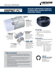
NOTE: The <strong>rps75</strong> is factory preset with a 180° arc <strong>setting</strong>, and includes a<br />
pre-installed #3 nozzle.<br />
Changing a Nozzle<br />
1. Removing the nozzle retention screw<br />
Use the hex (B) end of the Key to remove the nozzle retention screw by turning<br />
counter-clockwise to remove or clockwise to re-install.<br />
2. Pull up the riser<br />
Insert the (A) end of the Key in the keyhole (L) on the top of the nozzle turret (I)<br />
and turn the key 1/4 turn to insure that the key does not slip out of the keyhole<br />
when you pull it up. Firmly pull up the entire spring-loaded riser to access the<br />
nozzle socket (G). Hold the riser assembly with one hand.<br />
3. Removing the nozzle<br />
With nozzle retention screw removed, the nozzle may be removed by pulling<br />
outward on the nozzle prongs (D) with a pair of needle-nose pliers.<br />
4. Installing a nozzle<br />
Press the desired nozzle (C) into the nozzle socket (G). Make sure the nozzle<br />
number is visible and the nozzle “prongs” (D) are up. Then, re-install the nozzle<br />
retention screw (F). NOTE: The nozzle retention screw is also a break-up screw<br />
and used to adjust the distance of the spray.<br />
Setting the arc adjustment<br />
NOTE: The <strong>rps75</strong> Gear Driven Sprinkler has a fixed right start and an<br />
adjustable left stop.<br />
1. Positioning nozzle turret to its “Right Start”<br />
Place your fingers on the top center of the nozzle turret (I). Rotate the turret<br />
counter-clockwise to the left stop to complete any interrupted rotation cycle.<br />
Rotate the nozzle turret clockwise to the right start. This is the fixed side of the<br />
arc. The nozzle turret must be held in this position for arc adjustments. The right<br />
start does not change.<br />
2. Adjusting the Right (Fixed) Side of Arc<br />
If the right side of the arc is not properly aligned, the <strong>sprinkler</strong> may spray in areas<br />
not intended for watering such as driveways or adjacent properties. The right side<br />
arc can easily be realigned.<br />
Option 1: Reposition can on the fitting<br />
Turn the <strong>sprinkler</strong> can (K) and the fitting below it left or right to the desired<br />
position. This may require temporary removal of the soil around the <strong>sprinkler</strong><br />
to allow you to grip the <strong>sprinkler</strong> can.<br />
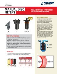
PERFORMANCE DATA<br />
PERFORMANCE<br />
PRESSURE RADIUS FLOW<br />
NOZZLES PSI FT. GPM<br />
#0.75 30 29' .7<br />
40 30' .8<br />
50 30' .9<br />
60 31' 1.0<br />
#1 30 30' 0.9<br />
40 31' 1.0<br />
50 31' 1.2<br />
60 32' 1.3<br />
#1.5 30 32' 1.2<br />
40 33' 1.4<br />
50 34' 1.6<br />
60 34' 1.8<br />
#2 30 34' 1.6<br />
40 36' 1.8<br />
50 38' 2.0<br />
60 38' 2.2<br />
#3 30 36' 2.0<br />
PRE- 40 38' 2.4<br />
INSTALLED<br />
50 40' 2.7<br />
60 40' 2.9<br />
#4 30 36' 2.6<br />
40 40' 3.0<br />
50 42' 3.4<br />
60 42' 3.7<br />
#6 40 38' 4.2<br />
50 43' 4.9<br />
60 46' 5.5<br />
70 47' 6.0<br />
#8 40 45' 6.0<br />
50 48' 6.8<br />
60 49' 7.6<br />
70 51' 8.2<br />
METRIC<br />
PRESSURE RADIUS FLOW<br />
NOZZLES KPA BARS METERS L/M M3/H<br />
#0.75 206 2.1 8.8 2.6 .16<br />
275 2.8 9.1 3.0 .18<br />
344 3.4 9.1 3.4 .20<br />
413 4.1 9.4 3.8 .23<br />
#1 206 2.1 9.1 3.4 .20<br />
275 2.8 9.4 3.8 .23<br />
344 3.4 9.4 4.5 .27<br />
413 4.1 9.8 4.9 .30<br />
#1.5 206 2.1 9.8 4.5 .27<br />
275 2.8 10.1 5.3 .32<br />
344 3.4 10.4 6.1 .36<br />
413 4.1 10.4 6.8 .41<br />
#2 206 2.1 10.4 6.1 .36<br />
275 2.8 11.0 6.8 .41<br />
344 3.4 11.6 7.6 .45<br />
413 4.1 11.6 8.3 .50<br />
#3 206 2.1 11.0 7.6 .45<br />
PRE- 275 2.8 11.6 9.1 .55<br />
INSTALLED<br />
344 3.4 12.2 10.2 .61<br />
413 4.1 12.2 11.0 .66<br />
#4 206 2.1 11.0 9.8 .59<br />
275 2.8 12.2 11.4 .68<br />
344 3.4 12.8 12.9 .77<br />
413 4.1 12.8 14.0 .84<br />
#6 206 2.1 11.6 15.9 .91<br />
275 2.8 13.1 18.5 1.11<br />
344 3.4 14.0 20.8 1.25<br />
413 4.1 14.3 22.7 1.36<br />
#8 275 2.8 13.7 22.7 1.36<br />
344 3.4 14.6 25.7 1.54<br />
413 4.1 14.9 28.8 1.73<br />
482 4.8 15.5 31.0 1.86<br />
* Data represents test results in zero wind. Adjust for local conditions. Radius may be reduced with nozzle retention screw.<br />
Option 2: Remove internal riser assembly and reposition<br />
Unscrew the top (H) counter-clockwise and remove the internal riser assembly<br />
from the can. Once removed with nozzle turret (I) at its right start, reposition<br />
the riser assembly so that nozzle arrow points to the desired start position.<br />
Replace the riser assembly back in the can and screw on the top. At this point<br />
you have realigned the right arc stop, and you can adjust the left arc to an<br />
appropriate <strong>setting</strong>.<br />
3. Adjusting the Left (Variable) side of the arc<br />
Increasing the arc<br />
Insert the (A) end of the Key into the arc set adjustment slot (M). While holding<br />
the nozzle turret (I) at the right start, turn the Key clockwise. Each full 360° turn<br />
of the Key will increase the arc 90°. Adjust to any arc between 40° and 360°.<br />
The Key will stop turning, or there will be ratcheting noise, when the maximum<br />
arc of 360° has been reached.<br />
Decreasing the Arc<br />
Insert the (A) end of the Key into the arc set adjustment slot (M). While holding<br />
the nozzle turret (I) at the right start, turn the Key counter-clockwise. Each full<br />
360° turn of the Key will decrease the arc 90°. Adjust to any arc between 40°<br />
and 360°. The Key will stop turning, or there will be a ratcheting noise, when<br />
the minimum arc of 40° has been reached.<br />
Sprinkler Installation<br />
1. Install and Bury<br />
Do not use pipe dope. Thread the <strong>sprinkler</strong> on the pipe. Bury the <strong>sprinkler</strong> flush<br />
on the same watering zone.<br />
2. Inspecting the filter<br />
Unscrew the top (H) and lift the complete <strong>sprinkler</strong> assembly (J) out of the can<br />
(K). The filter is located on the bottom of the <strong>sprinkler</strong> assembly and can be easily<br />
pulled out, cleaned and re-installed.<br />
3. Winterization Tips<br />
When using an air compressor to remove water from the system please note<br />
the following:<br />
a. Do not exceed 30 PSI.<br />
b. Always introduce air into the system gradually to avoid air pressure surges.<br />
Sudden release of compressed air into the <strong>sprinkler</strong> can cause damage.<br />
c. Each zone should run no longer than 1 minute on air. Sprinklers turn 10 to 12<br />
time faster on air than on water. Over spinning rotors on air can cause dam<br />
age to the internal components.<br />
M<br />
Arc Set<br />
Adjustment<br />
LOW ANGLE DATA<br />
PERFORMANCE<br />
L Keyhole<br />
PRESSURE RADIUS FLOW<br />
NOZZLES PSI FT. GPM<br />
#1 30 22' 1.2<br />
40 24' 1.7<br />
50 26' 1.8<br />
60 28' 2.0<br />
#3 30 29' 3.0<br />
40 32' 3.1<br />
50 35' 3.5<br />
60 37' 3.8<br />
#4 30 31' 3.4<br />
40 34' 3.9<br />
50 37' 4.4<br />
60 38' 4.7<br />
#6 40 38' 6.5<br />
50 40' 7.3<br />
60 42' 8.0<br />
70 44' 8.6<br />
I Nozzle Turret<br />
METRIC<br />
F Nozzle<br />
Retention<br />
Screw<br />
PRESSURE RADIUS FLOW<br />
NOZZLES KPA BARS METERS L/M M3/H<br />
#1 207 2.0 6.7 4.5 .34<br />
275 3.0 7.3 6.4 .39<br />
344 3.5 7.9 6.8 .41<br />
413 4.0 8.5 7.6 .46<br />
#3 207 2.0 8.8 11.4 .68<br />
275 3.0 9.8 11.7 .71<br />
344 3.5 10.7 13.2 .80<br />
413 4.0 11.3 14.4 .87<br />
#4 207 2.0 9.4 12.9 .78<br />
275 3.0 10.4 14.8 .89<br />
344 3.5 11.3 16.7 1.00<br />
413 4.0 11.6 17.8 1.07<br />
#6 275 3.0 11.6 24.6 1.68<br />
344 3.5 12.2 27.6 1.66<br />
413 4.0 12.8 30.3 1.82<br />
482 5.0 13.4 32.6 1.96<br />
F Nozzle<br />
Retention<br />
Screw<br />
G Nozzle<br />
Socket<br />
J Sprinkler<br />
Assembly<br />
C Nozzle<br />
D Nozzle Prongs<br />
STANDARD NOZZLE PERFORMAN<br />
U.S.<br />
Nozzle Pressure Radius Flow<br />
PSI Ft. GPM<br />
#3 30 36' 2.0<br />
40 38' 2.4<br />
50 40' 2.7<br />
60 40' 2.9<br />
E Key in Keyhole<br />
#0.5 30 28' 0.5<br />
40 29' 0.6<br />
50 29' 0.7<br />
60 30' 0.8<br />
#0.75 30 29' 0.7<br />
40 30' 0.8<br />
50 30' 0.9<br />
60 31' 1.0<br />
#1 30 30' 0.9<br />
40 31' 1.0<br />
50 31' 1.2<br />
60 32' 1.3<br />
K<br />
Can<br />
K-Rain Manufacturing Corp.<br />
1640 Australian Avenue<br />
Riviera Beach, FL 33404 USA<br />
PH: 1-561-844-1002 / 1-800-735-7246<br />
FAX: 1-561-842-9493<br />
WEB: http://www.krain.com<br />
© K-RAIN Manufacturing Corp. L-58917<br />
Part Number: 16005103 REV11<br />
B<br />
#2 30 32' 1.2<br />
40 33' 1.4<br />
50 34' 1.6<br />
60 34' 1.8<br />
#4 30 36' 2.6<br />
40 40' 3.0<br />
50 42' 3.4<br />
60 42' 3.7<br />
#6 30 38' 4.2<br />
40 43' 4.9<br />
50 46' 5.5<br />
60 47' 6.0<br />
#8 40 45' 6.0<br />
50 48' 6.8<br />
60 49' 7.6<br />
70 51' 8.2<br />
I<br />
Nozzle<br />
Turret<br />
METRI<br />
Pressure Radiu<br />
KPa Bars Meters<br />
H Top<br />
206 2.1 11.0<br />
275 2.8 11.6<br />
344 3.4 12.2<br />
413 4.1 12.2<br />
206 2.1 8.5<br />
275 2.8 8.8<br />
344 3.4 8.8<br />
413 4.1 9.1<br />
206 2.1 8.8<br />
275 2.8 9.1<br />
344 3.4 9.1<br />
413 4.1 9.4<br />
206 2.1 9.1<br />
275 2.8 9.4<br />
344 3.4 9.4<br />
413 4.1 9.8<br />
206 2.1 9.8<br />
275 2.8 10.1<br />
344 3.4 10.4<br />
413 4.1 10.4<br />
206 2.1 11.0<br />
275 2.8 12.2<br />
344 3.4 12.8<br />
413 4.1 12.8<br />
206 2.1 11.6<br />
275 2.8 13.1<br />
344 3.4 14.0<br />
413 4.1 14.3<br />
275 2.8 13.7<br />
344 3.4 14.6<br />
413 4.1 14.9<br />
482 4.8 15.5
Instrucciones de montaje DEL aspersor de turbina <strong>rps75</strong><br />
A<br />
RPS75 Llave<br />
Observación: El <strong>rps75</strong> viene configurado previamente de fábrica con un ajuste<br />
del sector a 180° e incluye la preinstalación de la tobera n.° 3.<br />
Cambio de la tobera<br />
1. Cómo quitar el tornillo de sujeción<br />
Utilice el extremo (B) de la llave, para quitar el tornillo de sujeción (F) de la tobera<br />
gire en el sentido contrario al de las agujas del reloj, y en el sentido de las agujas<br />
del<br />
PERFORMANCE<br />
reloj para volverlo a colocar.<br />
DATA<br />
2. Elevación del vástago<br />
PERFORMANCE<br />
METRIC<br />
Inserte el extremo (A) de la llave en el orificio (K) para extender la turbina y gire<br />
la llave ¼ de PRESSURE vuelta para RADIUS asegurarse FLOWde que la llave no PRESSURE se sale del RADIUS agujero FLOW cuando<br />
levante NOZZLES el aspersor. PSI Tire con FT. fuerza GPMpara acceder NOZZLES al hueco<br />
KPA BARS<br />
de la tobera<br />
METERS<br />
(G)<br />
L/M<br />
y sujete<br />
M3/H<br />
el #0.75 vástago con 30 una mano 29' para poder .7 acceder #0.75 al cambio 206 de 2.1 tobera. 8.8 2.6 .16<br />
40 30' .8<br />
275 2.8 9.1 3.0 .18<br />
3. Cómo quitar<br />
50<br />
la tobera<br />
30' .9<br />
344 3.4 9.1 3.4 .20<br />
60 31' 1.0<br />
413 4.1 9.4 3.8 .23<br />
Una #1 vez quitado 30 el tornillo 30' de sujeción 0.9 de #1 la tobera ésta 206 se 2.1 puede 9.1 sacar 3.4 tirando .20<br />
hacia fuera de los 40 dientes 31' de la tobera 1.0 (D) con unos alicates 275 2.8 (pinzas) 9.4 de 3.8 punta. .23<br />
50 31' 1.2<br />
344 3.4 9.4 4.5 .27<br />
4. Instalación 60 de una 32' tobera 1.3<br />
413 4.1 9.8 4.9 .30<br />
Inserte #1.5 presionando 30 la tobera 32' (C) 1.2 en su correspondiente #1.5 206 hueco 2.1 (G). 9.8 Asegúrese 4.5 .27 de<br />
que es visible el 40 número 33' de la tobera 1.4 y que los dientes<br />
275<br />
(D)<br />
2.8<br />
de ésta<br />
10.1<br />
están<br />
5.3<br />
hacia<br />
.32<br />
50 34' 1.6<br />
344 3.4 10.4 6.1 .36<br />
arriba. A continuación, 60 vuelva 34' a colocar 1.8 el tornillo de 413 sujeción 4.1 de 10.4 la tobera 6.8 (F). .41<br />
Observación: El tornillo de sujeción de la tobera también es un tornillo que<br />
#2 30 34' 1.6 #2 206 2.1 10.4 6.1 .36<br />
se utiliza para ajustar<br />
40<br />
el alcance<br />
36'<br />
del<br />
1.8<br />
chorro. 275 2.8 11.0 6.8 .41<br />
50 38' 2.0<br />
344 3.4 11.6 7.6 .45<br />
60 38' 2.2<br />
413 4.1 11.6 8.3 .50<br />
TABLAS DE RENDIMIENTO - TOBERAS ESTANDAR ´<br />
FUNCIONAMIENTO<br />
PRESIÓN RADIO CAUDAL<br />
TOBERA PSI FT. GPM<br />
#0.75 30 29' .7<br />
40 30' .8<br />
50 30' .9<br />
60 31' 1.0<br />
#1 30 30' 0.9<br />
40 31' 1.0<br />
50 31' 1.2<br />
60 32' 1.3<br />
#1.5 30 32' 1.2<br />
40 33' 1.4<br />
50 34' 1.6<br />
60 34' 1.8<br />
#2 30 34' 1.6<br />
40 36' 1.8<br />
50 38' 2.0<br />
60 38' 2.2<br />
#3 30 36' 2.0<br />
INSTALADO 40 38' 2.4<br />
PREVIAMENTE 50 40' 2.7<br />
60 40' 2.9<br />
#4 30 36' 2.6<br />
40 40' 3.0<br />
50 42' 3.4<br />
60 42' 3.7<br />
#6 40 38' 4.2<br />
50 43' 4.9<br />
60 46' 5.5<br />
70 47' 6.0<br />
#8 40 45' 6.0<br />
50 48' 6.8<br />
60 49' 7.6<br />
70 51' 8.2<br />
METRICO ´<br />
PRESIÓN RADIO CAUDAL<br />
TOBERA KPA BARES METROS L/M M3/H<br />
#0.75 206 2.1 8.8 2.6 .16<br />
275 2.8 9.1 3.0 .18<br />
344 3.4 9.1 3.4 .20<br />
413 4.1 9.4 3.8 .23<br />
#1 206 2.1 9.1 3.4 .20<br />
275 2.8 9.4 3.8 .23<br />
344 3.4 9.4 4.5 .27<br />
413 4.1 9.8 4.9 .30<br />
#1.5 206 2.1 9.8 4.5 .27<br />
275 2.8 10.1 5.3 .32<br />
344 3.4 10.4 6.1 .36<br />
413 4.1 10.4 6.8 .41<br />
#2 206 2.1 10.4 6.1 .36<br />
275 2.8 11.0 6.8 .41<br />
344 3.4 11.6 7.6 .45<br />
413 4.1 11.6 8.3 .50<br />
#3 206 2.1 11.0 7.6 .45<br />
INSTALADO 275 2.8 11.6 9.1 .55<br />
PREVIAMENTE 344 3.4 12.2 10.2 .61<br />
413 4.1 12.2 11.0 .66<br />
#4 206 2.1 11.0 9.8 .59<br />
275 2.8 12.2 11.4 .68<br />
344 3.4 12.8 12.9 .77<br />
413 4.1 12.8 14.0 .84<br />
#6 206 2.1 11.6 15.9 .91<br />
275 2.8 13.1 18.5 1.11<br />
344 3.4 14.0 20.8 1.25<br />
413 4.1 14.3 22.7 1.36<br />
#8 275 2.8 13.7 22.7 1.36<br />
344 3.4 14.6 25.7 1.54<br />
413 4.1 14.9 28.8 1.73<br />
482 4.8 15.5 31.0 1.86<br />
* Los datos representan resultados en pruebas efectuadas en el RPS75 sin viento.<br />
LOW ANGLE DATA<br />
Instalación PERFORMANCE del aspersor METRIC<br />
1. Instalación PRESSURE y RADIUS colocación FLOW<br />
PRESSURE RADIUS FLOW<br />
Determinación del ajuste del Arco<br />
NOZZLES PSI FT. GPM NOZZLES KPA BARS METERS L/M M3/H<br />
No utilice teflón o estopa en la rosca. Rosque el aspersor a la tubería. Entierre el<br />
Observación: #3 30 El aspersor 36' de turbina 2.0 <strong>rps75</strong> #3 dispone 206 de un 2.1 inicio 11.0 de 7.6 .45 #1 30 22' 1.2 #1 207 2.0 6.7 4.5 .34<br />
PRE- 40 38' 2.4 PRE- 275 2.8 11.6 9.1 .55<br />
aspersor a nivel 40 del suelo. 24' Observación: 1.7 Los 275 aspersores 3.0 de 7.3 turbina 6.4 y los .39 difusores<br />
arranque INSTALLEDfijo a la derecha y ajustable hacia INSTALLED la izquierda.<br />
50 40' 2.7<br />
344 3.4 12.2 10.2 .61 emergentes 50 no deben 26' ser instalados 1.8 en la misma 344 zona 3.5 de riego. 7.9 6.8 .41<br />
60 40' 2.9<br />
413 4.1 12.2 11.0 .66<br />
60 28' 2.0<br />
413 4.0 8.5 7.6 .46<br />
1. Colocación de la cabeza DE TOBERA giratoria en<br />
2. Inspección del filtro<br />
#4“Inicio de 30 arranque 36' a la 2.6 derecha” #4 206 2.1 11.0 9.8 .59 #3 30 29' 3.0 #3 207 2.0 8.8 11.4 .68<br />
40 40' 3.0<br />
275 2.8 12.2 11.4 .68 Desatornille 40 la tapa y 32' saque de 3.1la carcasa el aspersor. 275 3.0 El filtro 9.8 está 11.7 situado .71 en la<br />
Ponga los dedos 50 en la parte 42' superior 3.4 central de la cabeza 344 de 3.4 tobera 12.8 (I). 12.9 Gire la .77<br />
50 35' 3.5<br />
344 3.5 10.7 13.2 .80<br />
parte inferior<br />
60 42' 3.7<br />
413 4.1 12.8 14.0 .84<br />
60<br />
de la turbina<br />
37'<br />
y se<br />
3.8<br />
puede sacar, limpiar 413 y 4.0 volver 11.3 a instalar 14.4 fácilmente. .87<br />
cabeza de tobera en el sentido contrario al de las agujas del reloj (hasta oír un<br />
“clic” #6 en el tope 40 de la izquierda 38' y 4.2 así completar #6 el ciclo 206 de 2.1 rotación. 11.6 Gire 15.9 entonces .91 #4 3. Consejos 30 de cara 31' al 3.4 invierno #4 207 2.0 9.4 12.9 .78<br />
50 43' 4.9<br />
275 2.8 13.1 18.5 1.11<br />
40 34' 3.9<br />
275 3.0 10.4 14.8 .89<br />
la cabeza de tobera en el sentido de las agujas del reloj hacia el “inicio de<br />
60 46' 5.5<br />
344 3.4 14.0 20.8 1.25 Proceda a vaciar 50 las tuberías 37' 4.4 a fin de evitar los 344 daños 3.5 que ocasionan 11.3 16.7 las heladas. 1.00<br />
arranque a la derecha”. 70 Este 47' es el 6.0 lado fijo del arco. La 413 cabeza 4.1 de 14.3 tobera 22.7 habrá 1.36 Cierre la llave 60 general 38' del agua 4.7que suministra 413 la instalación 4.0 11.6 de riego. 17.8 Accione 1.07<br />
de mantenerse en esta posición para realizar el ajuste del arco. El “inicio de<br />
#8 40 45' 6.0 #8 275 2.8 13.7 22.7 1.36 después #6 en el 40 programador 38' de 6.5riego todas #6 las electro-válvulas, 275 3.0 11.6 hasta 24.6 desaguar 1.68 las<br />
arranque a la derecha” 50 no 48' cambia. 6.8<br />
344 3.4 14.6 25.7 1.54 tuberías. Anule 50 los riegos 40' programados 7.3 y ponga 344 el Programador 3.5 12.2 en 27.6 OFF (apagado) 1.66<br />
60 49' 7.6<br />
413 4.1 14.9 28.8 1.73 o desconéctelo 60 de la 42' toma de 8.0 energía eléctrica.<br />
413 4.0 12.8 30.3 1.82<br />
2. Ajuste del 70 lado derecho 51' 8.2(fijo) del arco482 4.8 15.5 31.0 1.86<br />
70 44' 8.6<br />
482 5.0 13.4 32.6 1.96<br />
Si * Data el lado represents derecho test results del arco in zero no wind. está Adjust correctamente for local conditions. alineado, Radius el may aspersor be reduced puede with rociar nozzle retention Al utilizar screw. un compresor de aire para eliminar el agua del sistema, tenga en cuenta<br />
en zonas no deseadas de riego como caminos o edificios. El lado derecho del arco lo siguiente:<br />
se puede volver a alinear fácilmente.<br />
Opción 1: Colocación del aspersor con el inicio del arco de riego.<br />
Gire la carcasa (J) del aspersor y su conexión situada debajo de ésta hacia la<br />
izquierda o hacia la derecha hasta la posición deseada de inicio del arco de<br />
riego. Para ello puede ser necesario retirar el césped o la tierra del suelo alrededor<br />
del aspersor para permitirle sujetar la carcasa con la mano.<br />
Opción 2: Retirar el ensamblaje interno del vástago y volverlo a<br />
colocar. Desenrosque la tapa (H) en el sentido contrario al de las agujas del reloj<br />
y saque de la carcasa el vástago con el muelle. Una vez quitado y con la cabeza<br />
de tobera en la posición de “inicio de arranque a la derecha”, vuelva a colocar el<br />
vástago en la carcasa de modo que la flecha de la tobera señale la posición de<br />
inicio de riego deseado y rosque la tapa en la carcasa. En este punto se habrá<br />
realineado el punto de inicio del arco a la derecha y se podrá ajustar el arco<br />
izquierdo hasta el arco de riego adecuado.<br />
3. Ajuste izquierdo (variable) del arco<br />
Aumento del sector de riego. Inserte el extremo (A) de la llave en la ranura<br />
de ajuste del arco (L). Mientras sujeta la cabeza de tobera en la posición de “inicio<br />
de arranque a la derecha”, gire la llave en el sentido de las agujas del reloj. Cada<br />
giro completo de 360° de la llave aumentará el arco 90°. Ajuste el arco entre los<br />
40° y 360°. La llave se detendrá o habrá un ruido de trinquete (matraca) cuando se<br />
haya alcanzado el arco máximo de 360°.<br />
Disminución del arco de riego. Inserte el extremo (A) de la llave en la ranura<br />
de ajuste del arco (L). Mientras sujeta la cabeza de tobera en la posición de “inicio<br />
de arranque a la derecha”, gire la llave en el sentido contrario al de las agujas del<br />
reloj. Cada giro completo de 360° de la llave disminuirá el arco 90°. Ajuste el arco<br />
entre los 40° y 360°. La llave se detendrá o habrá un ruido de trinquete (matraca)<br />
cuando se haya alcanzado el arco mínimo de 40°<br />
a. No exceda los 2.00 bares.<br />
b. Introduzca siempre aire en el sistema de forma gradual para evitar aumentos<br />
repentinos de la presión. Una salida repentina de aire comprimido al aspersor<br />
puede causar daños.<br />
c. Cada una de las zonas deberá funcionar con aire durante 1 minuto como<br />
máximo. Los aspersores giran entre 10 y 12 veces más rápido con aire que<br />
con agua. Un giro excesivo de los aspersores con aire puede causar daños<br />
a los componentes internos.<br />
K Orificio<br />
L<br />
Ajuste<br />
del<br />
Arco<br />
TOBERAS DE ANGULO ´ BAJO<br />
FUNCIONAMIENTO<br />
PRESIÓN RADIO CAUDAL<br />
TOBERA PSI FT. GPM<br />
#1 30 22' 1.2<br />
40 24' 1.7<br />
50 26' 1.8<br />
60 28' 2.0<br />
#3 30 29' 3.0<br />
40 32' 3.1<br />
50 35' 3.5<br />
60 37' 3.8<br />
#4 30 31' 3.4<br />
40 34' 3.9<br />
50 37' 4.4<br />
60 38' 4.7<br />
#6 40 38' 6.5<br />
50 40' 7.3<br />
60 42' 8.0<br />
70 44' 8.6<br />
I Cabeza de Tobera<br />
METRICO ´<br />
F Tornillo de<br />
Sujeción<br />
PRESIÓN RADIO CAUDAL<br />
TOBERA KPA BARES METROS L/M M3/H<br />
#1 207 2.0 6.7 4.5 .34<br />
275 3.0 7.3 6.4 .39<br />
344 3.5 7.9 6.8 .41<br />
413 4.0 8.5 7.6 .46<br />
#3 207 2.0 8.8 11.4 .68<br />
275 3.0 9.8 11.7 .71<br />
344 3.5 10.7 13.2 .80<br />
413 4.0 11.3 14.4 .87<br />
#4 207 2.0 9.4 12.9 .78<br />
275 3.0 10.4 14.8 .89<br />
344 3.5 11.3 16.7 1.00<br />
413 4.0 11.6 17.8 1.07<br />
#6 275 3.0 11.6 24.6 1.68<br />
344 3.5 12.2 27.6 1.66<br />
413 4.0 12.8 30.3 1.82<br />
482 5.0 13.4 32.6 1.96<br />
D Dientes de<br />
la Tobera<br />
F Tornillo<br />
de<br />
Sujeción<br />
G Hueco<br />
de<br />
Tobera<br />
J Aspersor<br />
C Tobera<br />
STANDARD NOZZLE PERFORMAN<br />
U.S.<br />
Nozzle Pressure Radius Flow<br />
PSI Ft. GPM<br />
#3 30 36' 2.0<br />
40 38' 2.4<br />
50 40' 2.7<br />
60 40' 2.9<br />
#0.5 30 28' 0.5<br />
40 29' 0.6<br />
50 29' 0.7<br />
60 30' 0.8<br />
E Llave en Orificio<br />
#0.75 30 29' 0.7<br />
40 30' 0.8<br />
50 30' 0.9<br />
60 31' 1.0<br />
#1 30 30' 0.9<br />
40 31' 1.0<br />
50 31' 1.2<br />
60 32' 1.3<br />
#2 30 32' 1.2<br />
40 33' 1.4<br />
50 34' 1.6<br />
60 34' 1.8<br />
K-Rain Manufacturing Corp.<br />
1640 Australian Avenue<br />
Riviera Beach, FL 33404 USA<br />
PH: 1-561-844-1002 / 1-800-735-7246<br />
FAX: 1-561-842-9493<br />
WEB: http://www.krain.com<br />
© K-RAIN Manufacturing Corp. L-58917<br />
Part Number: 16005103 REV11<br />
B<br />
#4 30 36' 2.6<br />
40 40' 3.0<br />
50 42' 3.4<br />
60 42' 3.7<br />
#6 30 38' 4.2<br />
40 43' 4.9<br />
50 46' 5.5<br />
60 47' 6.0<br />
#8 40 45' 6.0<br />
50 48' 6.8<br />
60 49' 7.6<br />
70 51' 8.2<br />
I Cabeza<br />
de<br />
Toberat<br />
METRI<br />
Pressure Radiu<br />
KPa Bars Meters<br />
206 2.1 11.0<br />
275 2.8 11.6<br />
344 3.4 12.2<br />
413 4.1 12.2<br />
206 2.1 8.5<br />
275 2.8 8.8<br />
344 3.4 8.8<br />
413 4.1 9.1<br />
206 2.1 8.8<br />
275 2.8 9.1<br />
344 3.4 9.1<br />
413 4.1 9.4<br />
206 2.1 9.1<br />
275 2.8 9.4<br />
344 3.4 9.4<br />
413 4.1 9.8<br />
206 2.1 9.8<br />
275 2.8 10.1<br />
344 3.4 10.4<br />
413 4.1 10.4<br />
206 2.1 11.0<br />
275 2.8 12.2<br />
344 3.4 12.8<br />
413 4.1 12.8<br />
206 2.1 11.6<br />
275 2.8 13.1<br />
344 3.4 14.0<br />
413 4.1 14.3<br />
275 2.8 13.7<br />
344 3.4 14.6<br />
413 4.1 14.9<br />
482 4.8 15.5<br />
H Tapa<br />
K<br />
Carcasa