Orbit WaterMaster 57623-57624-57625-57821 ... - Irrigation Direct
Orbit WaterMaster 57623-57624-57625-57821 ... - Irrigation Direct
Orbit WaterMaster 57623-57624-57625-57821 ... - Irrigation Direct

Create successful ePaper yourself
Turn your PDF publications into a flip-book with our unique Google optimized e-Paper software.
WTM001855 <strong>57623</strong>-24 rB.qxd 9/5/06 3:04 PM Page 1<br />
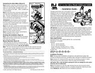
1. Attaching the Valves<br />
After flushing the lines, install the valve to the manifold with an adapter or nipple. Solvent weld versions can be cemented directly to the manifold<br />
using standard PVC solvent cement. For pipe thread versions, be sure to use thread tape generously on all male threads. Do Not<br />
Overtighten. Do not use pipe joint compound. Note arrow for water flow direction. Valves must be installed a minimum of 6” above the highest<br />
sprinkler head (check local codes). There must be no back pressure on the valve, and no valve on the downstream side of the anti-siphon.<br />
2. Attaching Sprinkler Lines<br />
Attach sprinkler lines to the valve with an adapter or nipple. Solvent weld versions can be cemented directly to the lines using standard PVC<br />
solvent cement. The use of a union at the inlet and outlet of each valve will allow for easy valve maintenance.<br />
3. Running the Wire<br />
With the power off, connect the valves to an <strong>Orbit</strong>® sprinkler timer or a residential standard 24 volt sprinkler timer. Use a multi-colored, multistrand<br />
jacketed sprinkler wire. Be sure the wire has at least one more strand than the number of valves in the manifold. Trench and run the<br />
wire to the valves. It is recommended, in areas that you will be frequently digging, that you use a section of PVC pipe as a protective covering.<br />
4. Attaching the Wire<br />
Attach a colored wire to one valve wire on the solenoid and a common wire to the other wire on the solenoid. It doesn’t matter which solenoid<br />
wire you use as the common. Attach the colored wires to the corresponding zone terminal in the timer and the common wire to the common<br />
connection in the timer. Use standard sprinkler wire (20 gauge) for distances less than 800 feet and 18 gage wire for over 800 feet. Use<br />
an <strong>Orbit</strong> Grease Cap and Wire Nut at each valve connection (See manifold assembly below). Also waterproof any splices made along the<br />
run.<br />
5. Close the Sprinkler Valves<br />
Make sure the Lifter, for internal manual bleed, is rotated clockwise to the closed. The flow control stem should be in the fully open (counterclockwise)<br />
position.<br />
6. Test the System<br />
After all pipe and fittings have been installed (allowing sufficient time for PVC glued joints to dry—24 hours), turn the water supply on and<br />
check for leaks with the valves closed. The valves may come on momentarily while initially pressurizing the line, but will shut off in a few<br />
moments.<br />
7. Open Valves<br />
Turn the manual bleed Lifter counter-clockwise to manually open the valve. Check the downstream pipe and fittings for leaks. Now close the<br />
Lifter. The valve will shut off in a few moments. The system is now ready to be controlled electrically from the timer or manually by opening<br />
the internal manual bleed Lifter. (Caution: Frequent manual operation of the valve using the internal manual bleed Lifter is not recommended.<br />
This type of manual operation is for trouble-shooting and occasional use.)<br />
8. Adjusting the Flow control<br />
The optional flow control stem can be adjusted to control the water flow or output pressure from the valve. This is especially useful when the<br />
valve is used for watering flowers, shrubs or garden areas. Adjust the flow control stem top of the valve (clockwise to restrict flow, counterclockwise<br />
to increase the flow). NOTE: The flow control stem is not a positive shut-off.<br />
9. Draining<br />
In freezing areas, the valves and lines will need to be drained. Refer to the <strong>Orbit</strong> ® Layout Guide or your local dealer to recommend proper<br />
drain points. To insure the electric valves are completely drained in the fall, turn off the main sprinkler shut-off valve and electrically run each<br />
valve dry for a few minutes. Turn the timer to the “off” position until spring.<br />
NOTES:<br />
• For outdoor use on cold water only. Valves should be placed so that water drains away from the house. If you will not be using culinary<br />
water, you must use a filter up-stream of the valve(s).<br />
• All manifolds should be made of Schedule 40 PVC Pipe or Galvanized Fittings and Pipe. The use of <strong>Orbit</strong>’s ® Manifold Fittings is an easy<br />
method of building an expandable yet easy to service manifold assembly with built-in unions.<br />
• Local codes specify location and type of valves required. Check local codes for installation requirements.<br />
• If static water pressure exceeds 80 PSI, a pressure regulator should be used.<br />
• Valves must be installed a minimum of 6” above the highest sprinkler head (check local codes). There must be no back pressure on the<br />
valve, and no valve on the downstream side of the anti-siphon.<br />
• Pressure test all water lines and electrically test all timer connections before covering pipe and timer control wire.<br />
• All Metal Parts are<br />
Stainless Steel<br />
• Unique Molded<br />
Diaphragm Design<br />
• Heavy Duty<br />
Corrosion Resistant<br />
PVC Body<br />
INSTALLATION INSTRUCTIONS<br />
FEATURES OF THE MOLDED DIAPHRAGM ANTI-SIPHON VALVE<br />
Flow Control<br />
Low Voltage Solenoid<br />
Lifter for Internal<br />
Manual Operation<br />
PROBLEM: THE VALVE WILL NOT CLOSE.<br />
Check If...<br />
1- The valve is installed incorrectly<br />
2- Lifter in open position<br />
3- Solenoid plunger is stuck<br />
4- Rock or debris is between the<br />
washer and the valve seat<br />
5- Diaphragm has ruptured<br />
PROBLEM: EXTERNAL VALVE LEAKS<br />
Check If...<br />
1- PVC fittings going into<br />
valve installed incorrectly<br />
2- Pressure is too high<br />
3- Water is Leaking around screws<br />
4- Leaking below Solenoid<br />
5- Leaking around the Anti-Siphon Lid<br />
ELECTRIC VALVE TROUBLE SHOOTING<br />
Your <strong>Orbit</strong> ® Anti-Siphon valve should provide years of trouble-free service. However, if you do have any problems, try the following solutions.<br />
PROBLEM: THE VALVE WILL NOT OPEN<br />
First, attempt to open the valve manually by lifting the internal manual bleed Lifter (counterclockwise). If the valve will not operate manually:<br />
Check If<br />
1. The valve is installed incorrectly<br />
PROBLEM: THE VALVE WILL NOT OPEN ELECTRICALLY<br />
Check If...<br />
1 The wiring and timer are<br />
installed correctly<br />
2.There is debris in the port hole<br />
3. Defective Solenoid<br />
4. Solenoid plunger is stuck<br />
5. Pressure is too high<br />
Flow Control Stem<br />
✰<br />
Lid Sub-Assembly<br />
Diaphragm Assembly<br />
Solution<br />
Make sure that the arrows are in the direction of water flow and that the flow control is in the open<br />
(turn counterclockwise until fully open) position. Check the water supply line for water pressure.<br />
Solution<br />
Check the wiring at the valve and at the timer (refer to your timer instructions). Also, check<br />
to see that the timer is working properly including the timer’s transformer, fuse (or reset button),<br />
and programming.<br />
Turn off the water. Remove the Solenoid. Push a wire or large paper clip down through the<br />
round port hole, working it up and down to free any debris. Be sure the plunger and O-ring<br />
are in place when reassembling the solenoid on the valve.<br />
Turn off the water. Unscrew the Solenoid and replace with one from a working valve. If the valve now<br />
works, replace the defective Solenoid. Be sure the plunger and O-ring are in place when reassembling.<br />
Turn off the water. Remove the solenoid and clean out sand and debris. Be sure the plunger<br />
and O-ring are in place when reassembling them on the valve.<br />
Install a pressure regulator valve and set at about 80 PSI.<br />
Solution<br />
Make sure that the arrows are in the direction of the water flow.<br />
Check that the internal manual bleed Lifter is in the closed position (clockwise).<br />
Turn off water. Remove Solenoid and clean sand and debris. Be sure the plunger and O-ring are<br />
in place when reassembling them on the valve.<br />
Turn off the water. Remove the valve lid and Diaphragm assembly and clean the interior<br />
of the valve.<br />
Turn off the water. Remove the lid and inspect the Diaphragm for tears. Replace the<br />
Diaphragm assembly if torn.<br />
Solution<br />
Use teflon tape generously on threads and tighten firmly. Do not overtighten. Do not use<br />
pipe joint compound.<br />
Install a pressure regulator upstream of the valve and set at about 80 PSI.<br />
Turn off the water. Undo the leaking screw 4 or 5 turns and retighten firmly.<br />
Turn off the water. Tighten the Solenoid.<br />
Verify that the valve is installed a minimum of 6” above the highest sprinkler head<br />
(check local codes). A small amount of leakage while the valve is turning on or off is normal.<br />
For large leaks, loosen the Anti-Siphon lid and check the condition of the lid gasket and<br />
the seal carrier.<br />
PARTS LISTING<br />
Spring<br />
Solenoid Assembly<br />
57041<br />
Anti-Siphon Lid<br />
& Lid Top<br />
Lid Top Gasket<br />
Seal Carrier<br />
AUTOMATIC ANTI-SIPHON<br />
CONTROL VALVE<br />
<strong>57623</strong>, <strong>57624</strong>, <strong>57625</strong>, <strong>57821</strong>, 57823, 57824, 91112<br />
INSTRUCTIONS FOR OPERATION<br />
This Automatic Anti-Siphon Control Valve is an IAPMO listed, 3/4” or 1”, low voltage (24 volt)<br />
molded diaphragm valve with internal manual operation.<br />
OTHER ORBIT ® PRODUCTS<br />
PRODUCT PART NUMBER BENEFIT/DESCRIPTION OF USE<br />
Automatic Rain Shut Off 57069 Automatically interrupts the<br />
57070 watering cycle of the sprinkler<br />
57071 timer when it rains<br />
Weather 57095 Allows outdoor installation of<br />
Resistant Timer Box<br />
any brand of indoor mount<br />
timer. UL ® listed<br />
Pump Start Relay 57009 Automatically activates a pump for<br />
automatic watering (i.e. with well water).<br />
To Sprinkler<br />
Heads<br />
Grease Caps<br />
MANIFOLD ASSEMBLY<br />
Static Water<br />
Pressure Side<br />
(bars) (psi)<br />
3.4 50<br />
3.1 45<br />
2.8 40<br />
2.4 35<br />
2.1 30<br />
Pressure<br />
1.7 25<br />
Loss<br />
1.4 20<br />
1.0 15<br />
0.7 10<br />
0.3 5<br />
0 0<br />
✰<br />
Body<br />
Flow Rate vs. Pressure Loss<br />
Anti-Siphon Body<br />
FRICTION LOSS CHART FOR ANTI-SIPHON VALVES<br />
Solenoid electrical specifications:<br />
Inrush volt-amps<br />
@ 24 VAC = 8.4 VA<br />
Inrush current<br />
@ 24 VAC = 0.35 AMPS<br />
Holding volt-amps<br />
@ 24 VAC = 5.5 VA<br />
Holding current<br />
@ 24 VAC = 0.23 AMPS<br />
<strong>Orbit</strong> ® <strong>Irrigation</strong> Products, Inc.<br />
North Salt Lake, UT 84054<br />
1-800-488-6156<br />
www.orbitonline.com<br />
ORBIT ® UNLIMITED 6 YEAR WARRANTY<br />
<strong>Orbit</strong> ® <strong>Irrigation</strong> Products, Inc. warrants to its customers that its <strong>Orbit</strong> ® products will be free from defects in<br />
materials and workmanship for a period of six years from the date of purchase. We will replace, free of<br />
charge, the defective part or parts found to be defective under normal use and service for a period of up<br />
to six years after purchase: proof of purchase is required. We reserve the right to inspect the defective part<br />
prior to replacement. <strong>Orbit</strong> ® <strong>Irrigation</strong> Products, Inc. will not be responsible for consequential or<br />
incidental cost or damage caused by the product failure.The liability of <strong>Orbit</strong> ® <strong>Irrigation</strong> Products, Inc. under<br />
this warranty is limited solely to the replacement or repair of defective parts.<br />
To Sprinkler Heads<br />
From Main Sprinkler<br />
Shut-Off<br />
0 5 10 15 20 25 30 35<br />
(gpm)<br />
0 19 38 57 76 95 114 136 (liters/min)<br />
Flow Rate<br />
3/4” Anti-Siphon Valve<br />
1” Anti-Siphon Valve<br />
<strong>57623</strong>-24 Rev B
WTM001855 <strong>57623</strong>-24 rB.qxd 9/5/06 3:04 PM Page 2<br />
INSTRUCCIONES PARA LA INSTALACION<br />
1. Unión de las válvulas<br />
Después de lavar la tubería, conecte la válvula al montaje múltiple usando una boquilla. Versiones de la válvula para soldadura de cemento pueden<br />
pegarse directamente a la linea usando estandar PVC cemento. Para opciones de pipa roscada asegúrese de usar cinta roscada en todas las roscas<br />
macho. No apriete demasiado. No use material para unir tubos. Fíjese en la flecha que indica el flujo del agua. Las válvulas se deben instalar a un<br />
mínimo de 6 pulgadas (15 cm.) de la boquilla de aspersor más alta (compruebe los códigos locales). No debe existir presión contraria en la válvula, ni<br />
válvula alguna en el lado del anti-sifón por donde baja la corriente.<br />
2. Unión de los tubos del sistema de aspersores<br />
Una los tubos del sistema de aspersores a la válvula con un adaptador. Versiones de la válvula para soldadura de cemento pueden pegarse directamente<br />
a la linea usando estandar PVC cemento. Usar un adaptador de unión en los dos extremos de cada válvula facilitará el fácil mantenimiento de<br />
las válvulas.<br />
3. Instalación de cables<br />
Con la electricidad apagada, conecte las válvulas a un timer <strong>Orbit</strong>® para aspersor o a un timer residencial estándar para aspersor de 24 volts. Use<br />
cables de colores múltiples multitrenza aprobado para un sistema de aspersores. Asegúrese de que el cable tenga por lo menos una trenza más que<br />
el número de válvulas requeridas en el montaje múltiple. Trinche el cable y pasarlo a las válvulas. En áreas donde tenga que cavar con frecuencia, se<br />
recomienda que use un pedazo de tubo de cloruro de polivinilo como cubierta protectora (PVC).<br />
4. Conexión de cables<br />
Conecte un cable de color a un cable de válvula del solenoide y un cable común al otro cable del solenoide. No importa cual de los cables utilice<br />
como el cable común. Conecte los cables de colores al terminal correspondiente de zona del regulador y el cable común a la conección común en el<br />
regulador. Use cable normal o estándar para sistema de aspersores (calibre 20) para distancias menores de 800 pies (244 metros) y de calibre 18<br />
para distancias mayores de 800 pies. En cada conexión de válvulas use una tapa de grasa <strong>Orbit</strong> y una tuerca (vea el ejemplo de un montaje múltiple<br />
abajo). Impermeabilice además cualquier empalme que haya hecho en el cable.<br />
5. Cierre de las válvulas del sistema de aspersores<br />
Asegúrese de girar el Propulsor para descarga manual interna en el sentido de las agujas del reloj hasta la posición de cierre. La manija del control de<br />
flujo debe estar completamente abierta (dé vueltas en sentido contrario a las manecillas del reloj).<br />
6. Prueba del sistema<br />
Tras habersen instalado todos los tubos y adaptadores (permitiendo que pase suficiente tiempo para que las uniones se hayan secado—24 horas),<br />
abra el abastecimiento de agua y asegúrese de que no hayan escapes cuando las válvulas estén cerradas. Es posible que las válvulas se prendan<br />
por unos momentos cuando se le añada presión a la tubería, pero se apagarán casi inmediatamente.<br />
7. Válvulas abiertas y ajuste del control del flujo<br />
Gire el Propulsor para descarga manual interna en sentido contrario a las agujas del reloj para abrir manualmente la válvula. Compruebe si el tubo por<br />
donde corre el agua y los adaptadores presentan algún escape. Ya cierre el elevador. La válvula se apagará en pocos momentos. Ahora el sistema<br />
puede controlarse eléctricamente desde el regulador o manualmente por medio del tornillo de drenaje. (PRECAUCION: No se recomienda la frecuente<br />
operación manual de la válvula usando control de drenaje interno. Esta clase de operación manual es en caso de reparación o para uso ocasional).<br />
8. Ajustando el control de flujo<br />
La manija para el control de flujo es opcional y se puede ajustar para controlar el flujo de agua o presión. Esto es especialmente útil cuando la válvula<br />
es usada para regar flores, arbustos o áreas especiales del jardín. Ajuste el flujo de control dando vueltas a la manija encima de la valvula (A la<br />
derecha para limitar el corriente, a la izquierda para aumentar el corriente). Nota. La manija para el control de flujo se debe usar solamente para controlar<br />
el flujo de agua. No se debe usar para parar completamente el flujo de agua.<br />
9. Drenaje o desague<br />
En áreas donde las temperaturas llegan a un nivel de congelamiento, se deben vaciar las válvulas y las cañerías. Para saber qué es lo que se<br />
recomienda para el desague, refiérase a las instrucciones dadas por la compañía (<strong>Orbit</strong> Layout Guide) o comuníquese con el distribuidor local. Para<br />
asegurar que la válvula eléctrica quede completamente seca durante el otoño, cierre la válvula de interrupción del sistema principal y deje que por<br />
unos minutos cada válvula se seque electricamente. Apaque el regulador hasta la primavera.<br />
NOTAS:<br />
• Unicamente para uso al aire libre con agua fría. Las válvulas se deben instalar para que el desague salga hacia el lado opuesto de la casa.<br />
Si no va a utilizar agua potable, deberá usar un filtro que se coloca al comienzo de la válvula.<br />
• Todo montaje múltiple debe hacerse con tubo de 40 de cloruro de polivinilo (Schedule 40 PVC Pipe) o con adaptadores y tubos galvanizados.<br />
El uso de adaptadores distribuidor de <strong>Orbit</strong> ® es un método fácil para hacer un ensamblaje múltiple y expandible con uniones ya incorporadas.<br />
• Los códigos locales especifican el lugar y el tipo de válvulas que se requieren. Examine los códigos locales para saber cuáles son los requisitos<br />
para la instalación.<br />
• Las válvulas se deben instalar a un mínimo de 6 pulgadas (15 cm.) de la boquilla de aspersor más alta (compruebe los códigos locales). No debe<br />
existir presión contraria en la válvula, ni válvula alguna en el lado del anti-sifón por donde baja la corriente.<br />
• Si la presión estática del agua excede 80 PSI (libras por pulgada cuadrada), se debe usar un regulador para la presión.<br />
• Donde sea posible, proteja la válvula con una caja para válvulas y en el fondo coloque arena o cascajo.<br />
• Antes de cubrir con tierra la tubería y el alambre del regulad, pruebe la presión del agua de todas las tuberías y pruebe eléctricamente los conectores<br />
CARACTERISTICAS DE LA VALVULA ANTI-SIFON<br />
La válvula en linea debe proporcionarle muchos años de servicio sin problemas. Ni modo, si tiene algún problema, trate las soluciones siguientes.<br />
PROBLEMA: LA VALVULA NO ABRE<br />
Primero, trate de abrir la válvula manualmente por levantar el elevador de desague manual (a la izquierda). Si no se opera la válvula manualmente<br />
debe hacer lo siguiente:<br />
Posible Causa:<br />
Solución:<br />
1. La Válvula está instalada incorrectamente Asegure que las flechas vayan en dirección del flujo o corriente del agua y que el control<br />
del flujo está en la posición de encendido. Examine la línea de entrada del agua.<br />
PROBLEMA: LA VALVULA NO ABRE ELECTRONICAMENTE<br />
Posible Causa:<br />
1. El cable regulador están<br />
instalados correctamente<br />
2. Hay desechos en el orificio redondo<br />
3. El solenoide está defectuoso<br />
4. El pistón del solenoide está atascado<br />
5. La presión es muy alta<br />
PROBLEMA: LA VALVULA NO CIERRA CUANDO SE ENCIENDE EL REGULADOR<br />
Posible causa:<br />
1. La válvula está instalada incorrectamente.<br />
2. El elevador está en posición abierta.<br />
3. El pistón del solenoide está atascado.<br />
4. Hay desechos entre la arandela de goma<br />
y el asiento de la válvula.<br />
5. El diafragma está roto.<br />
PROBLEMA: HAY ESCAPE DE AGUA DE LA VALVULA<br />
Posible causa:<br />
1. Los adaptadores de cloruro de polivinilo<br />
se han instalado incorrectamente.<br />
2. La presión es demasiado alta.<br />
3. Hay escape de agua<br />
alrededor de los tornillos.<br />
4. Hay escape debajo del solenoide.<br />
5. Escape alrededor de la<br />
tapa del Anti-sifón.<br />
SOLUCIONES A LOS PROBLEMAS DE LAS VALVULAS<br />
Solución:<br />
Examine el cable a la válvula y al regulador (refiérase a las instrucciones para el regulado).<br />
También, asegure que el regulador está funcionando correctamente incluindo el<br />
transformador del regulador, el fusible ( o el butón de refijar ) y la programación.<br />
Cierre el agua. Quite el solenoide. Inserte un cable o un clip de metal largo por el orificio<br />
redondo para asegurar que no esté atascado. Asegure que el pistón y la compuerta O (Oring)<br />
se hayan colocado en el lugar indicado cuando se vuelva a montar el solenoide.<br />
Cierre el agua. Destornille el solenoide y cámbielo con uno de una válvula que esté<br />
funcionando. Ahora si la válvula funciona, substituya el solenoide defectuoso.<br />
Asegúrese de que el pistón y la compuerta O-ring se hayan colocado debidamente<br />
cuando se vuelva a montar.<br />
Cierre el agua. Quite el solenoide y limpie la arena o la basura que se haya acumulado.<br />
Asegúrese de que el pistón y la compuerta O-ring se hayan colocado debidamente<br />
cuando se vuelva a montar.<br />
Instale una válvula reguladora de presión y fijela a una presión de 80 PSI (libras por<br />
pulgada cuadrada).<br />
Solución:<br />
Asegure que las flechas vayan en dirección del flujo del agua.<br />
Compruebe que el control de drenaje interno está en posición cerrada (en dirección<br />
de las manecillas del reloj).<br />
Cierre la llave del agua. Quite el solenoide y lávelo para que no tenga arena ni<br />
desechos. Asegure que el pistón y la compuerta O (O-ring) se hayan colocado en el<br />
lugar indicado cuando se vuelva a montar.<br />
Cierre la llave del agua. Quite la parte superior o tapa de la válvula y limpie su interior.<br />
Cierre la llave del agua. Quite la tapa y asegure que el diafragma no esté roto. Si el<br />
diafragma está roto cambielo, haga lo mismo si el limpiador se ha perdido.<br />
Solución:<br />
Use cinta teflón en la rosca y apriete con alicates. No apriete demasiado.No use<br />
mixtura para empalme de tudo.<br />
Instale una válvula reguladora de presión y fije aproximadamente a 80 PSI (libras por<br />
pulgada cuadrada).<br />
Cierre la llave del agua. Destornille el tornillo de escape entre 4 a 5 vueltas y vuelva a<br />
apretarlo bien.<br />
Cierre la llave del agua. Apriete el solenoide.<br />
Asegúrese de que la válvula se haya instalado a un mínimo de 6 pulgadas (15 cm.) de<br />
la boquilla de aspersor más alta (compruebe los códigos locales). Es normal que exista<br />
una pequeña cantidad de escape cuando se apriete o se suelte la válvula. Cuando el<br />
escape sea grande, suelte la tapa del Anti-sifón y examine la condición de la empaquetadura<br />
de la tape y del conductor sellante.<br />
VALVULA DE CONTROL<br />
AUTOMATICO ANTI-SIFON<br />
<strong>57623</strong>, <strong>57624</strong>, <strong>57625</strong>, <strong>57821</strong>, 57823, 57824, 91112<br />
INSTRUCCIONES PARA EL FUNCIONAMIENTO U OPERACION<br />
La válvula de control automático Anti-Sifón es aprobada por IAPMO. La válvula mide 3/4 de pulgada o 1 pulgada, es<br />
de bajo voltaje (24 voltios), y tiene un diafragma moldeado con operación manual interna.<br />
NOMBRE<br />
NUMERO DE LA PARTE<br />
Apagador automático 57069<br />
en caso de lluvia 57070<br />
(sensor automático) 57071<br />
OTROS PRODUCTOS ORBIT<br />
®<br />
BENEFICIOS/DESCRIPCION DEL USO<br />
Interrumpe automáticamente el ciclo de riego del<br />
timer del aspersor cuando llueve.<br />
• Todas las partes metálicas<br />
son de acero inoxidable<br />
• Diseño único de diafragma<br />
moldeado<br />
Control de flujo<br />
Cables que van<br />
al regulador<br />
Solenoide de<br />
bajo voltaje<br />
Control de flujo<br />
LISTA DE PARTES<br />
Montaje del solenoide<br />
57041<br />
Caja del a Regulador 57095<br />
prueba de<br />
inclemencias UL ®<br />
Relé de arranque 57009<br />
de bomba<br />
Permite que se instale al aire libre cualquier tipo de<br />
regulador de la lista UL ® fabricado para el montaje<br />
interior.<br />
Activa la bomba automáticamente para el riego<br />
automático (por ejemplo, con agua de pozo).<br />
• Su parte principal y su<br />
tapa son de material<br />
reforzado y anticorrosivo<br />
Control de<br />
drenaje interno<br />
*Sub-montaje<br />
de la tapa<br />
Resorte<br />
A las cabezas del sistema<br />
de aspersores<br />
Lado con presión<br />
estática del agua<br />
Montaje del diafragma<br />
*Sub-montaje de<br />
la parte principal<br />
<strong>Orbit</strong> ® <strong>Irrigation</strong> Products, Inc.<br />
North Salt Lake, UT 84054<br />
1-800-488-6156<br />
www.orbitonline.com<br />
EJEMPLO DE UN MONTAJE MULTIPLE<br />
Tapas de grasa<br />
Cable común<br />
Exterior (al regulador)<br />
DIAGRAMA DE PERDIDA DE PRESION PARA VALVULA ANTI-SIFON<br />
ORBIT ® SEIS AÑOS DE GARANTIA ILIMITADA<br />
A las cabezas<br />
del sistema de<br />
aspersores<br />
Del interruptor del<br />
sistema principal de<br />
aspersores o aparato<br />
antisifón del tubo<br />
principal<br />
1.4<br />
1.2<br />
1.1<br />
1<br />
0.8<br />
Pérdida de<br />
0.7<br />
presión (psi)<br />
0.6<br />
0.4<br />
0.3<br />
0.1<br />
0<br />
20<br />
18<br />
16<br />
14<br />
12<br />
10<br />
8<br />
6<br />
4<br />
2<br />
0<br />
Pérdida de presión vs.<br />
desplazamiento volumétrico (gpm)<br />
0 5 10 15 20 25 30 35<br />
(gpm)<br />
0 19 38 57 76 95 114 136 (liters/min)<br />
Desplazamiento volumétrico (gpm)<br />
Los requisitos eléctricos mínimos son de 18 voltios de corriente<br />
alterna (A.C.) en el solenoide.<br />
Volt-amps de entrada<br />
@ 24 V.A.C.= 11.5 VA<br />
Corriente de entrada<br />
@ 24 V.A.C.= 48 AMPS<br />
Retención de volt-amps<br />
@ 24 V.A.C.= 5.75 VA<br />
Corriente de retención<br />
@ 24 V.A.C.= 24 AMPS<br />
Válvula anti-sifón de 3/4 de pulgada<br />
Válvula anti-sifón de 1 de pulgada<br />
<strong>Orbit</strong> ® <strong>Irrigation</strong> Products, Inc. garantiza a sus clientes que sus productos <strong>Orbit</strong> ® estarán libres de desperfectos<br />
en material y mano de obra por un período de seis años a partir de la fecha de compra. La<br />
compañía reemplazará, sin cargo alguno, la parte o las partes que se compruebe que se hayan deteriorado<br />
con un uso normal, por un período de seis años a partir del momento de efectuada la compra.<br />
<strong>Orbit</strong> ® <strong>Irrigation</strong> Products, Inc. se reserva el derecho de inspeccionar la parte defectuosa antes<br />
de reemplazarla. La compañía no se hace responsable de ningún costo por daños causados por el<br />
desperfecto del producto. La responsabilidad de <strong>Orbit</strong> ® <strong>Irrigation</strong> Products, Inc. dentro del marco de<br />
esta garantía se limita sólo al cambio o reparación de las partes defectuosas.
WTM001855 <strong>57623</strong>-24 rB.qxd 9/5/06 3:04 PM Page 3<br />
WTM001855 <strong>57623</strong>-24 RB.QXD<br />
ORBIT<br />
046878<br />
16.5”<br />
12” XX<br />
BLACK<br />
NOT USED<br />
NOT USED<br />
NOT USED<br />
SM<br />
XX<br />
XX<br />
WTM001855<br />
08/24/06<br />
2<br />
3<br />
NOT USED<br />
NOT USED<br />
NOT USED<br />
NOT USED