ensayes ante cargas laterales cÃclicas reversibles de un edificio ...
ensayes ante cargas laterales cÃclicas reversibles de un edificio ...
ensayes ante cargas laterales cÃclicas reversibles de un edificio ...

You also want an ePaper? Increase the reach of your titles
YUMPU automatically turns print PDFs into web optimized ePapers that Google loves.
Mario Rodríguez y John Blandón<br />
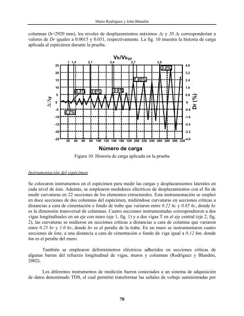
columnas (h=2920 mm), los niveles <strong>de</strong> <strong>de</strong>splazamientos máximos ∆ Y y 20 ∆ Y correspon<strong>de</strong>rían a<br />
valores <strong>de</strong> Dr iguales a 0.0015 y 0.031, respectivamente. La fig. 10 muestra la historia <strong>de</strong> carga<br />
aplicada al espécimen dur<strong>ante</strong> la prueba.<br />
25<br />
20<br />
1 1.4 2.1 2.4 2.7 2.5<br />
3.0%<br />
4.0<br />
3.2<br />
15<br />
1.95%<br />
2.4<br />
∆/∆y<br />
10<br />
5<br />
0<br />
-5<br />
-10<br />
0.2%<br />
0.3% 0.6% 0.9%<br />
Vb/Vb DF<br />
-4.0<br />
1.6<br />
0.8<br />
0<br />
-0.8<br />
-1.6<br />
Dr (%)<br />
-15<br />
-2.4<br />
-20<br />
-3.2<br />
-25<br />
20<br />
40 60 80 100 120 140 160 180 200 220 240 260 280 300 320<br />
Número <strong>de</strong> carga<br />
Figura 10. Historia <strong>de</strong> carga aplicada en la prueba<br />
Instrumentación <strong>de</strong>l espécimen<br />
Se colocaron instrumentos en el espécimen para medir las <strong>cargas</strong> y <strong>de</strong>splazamientos <strong>laterales</strong> en<br />
cada nivel <strong>de</strong> éste. A<strong>de</strong>más, se emplearon medidores eléctricos <strong>de</strong> <strong>de</strong>splazamientos con el fin <strong>de</strong><br />
medir curvaturas en 22 secciones <strong>de</strong> los elementos estructurales. Esta instrumentación se empleó<br />
en doce secciones <strong>de</strong> dos columnas <strong>de</strong>l espécimen, midiéndose curvaturas en secciones críticas a<br />
distancias a cara <strong>de</strong> cimentación o fondo <strong>de</strong> trabe que variaron entre 0.22 hc y 0.85 hc, don<strong>de</strong> hc<br />
es la dimensión transversal <strong>de</strong> columnas. Cuatro secciones instrumentadas correspondieron a dos<br />
vigas longitudinales en <strong>un</strong> eje con muro (eje 1, fig. 1) y a dos vigas T en el eje central (eje 2, fig.<br />
2), las curvaturas se midieron en secciones críticas a distancias a cara <strong>de</strong> columna que variaron<br />
entre 0.25 hv y 1.0 hv, don<strong>de</strong> hv es el peralte <strong>de</strong> la trabe. En <strong>un</strong> muro se instrumentaron cuatro<br />
secciones <strong>de</strong> éste, a <strong>un</strong>a distancia a cara <strong>de</strong> cimentación o fondo <strong>de</strong> viga igual a 0.12 hm, don<strong>de</strong><br />
hm es el peralte <strong>de</strong>l muro.<br />
También se emplearon <strong>de</strong>formímetros eléctricos adheridos en secciones críticas <strong>de</strong><br />
alg<strong>un</strong>as barras <strong>de</strong>l refuerzo longitudinal <strong>de</strong> vigas, muros y columnas (Rodríguez y Blandón,<br />
2002).<br />
Los diferentes instrumentos <strong>de</strong> medición fueron conectados a <strong>un</strong> sistema <strong>de</strong> adquisición<br />
<strong>de</strong> datos <strong>de</strong>nominado TDS, el cual permitió transformar las señales <strong>de</strong> voltaje suministradas por<br />
70