GAS WALL OVEN INSTALLATION INSTRUCTIONS - Appliances
GAS WALL OVEN INSTALLATION INSTRUCTIONS - Appliances
GAS WALL OVEN INSTALLATION INSTRUCTIONS - Appliances

You also want an ePaper? Increase the reach of your titles
YUMPU automatically turns print PDFs into web optimized ePapers that Google loves.
<strong>GAS</strong> <strong>WALL</strong> <strong>OVEN</strong> <strong>INSTALLATION</strong> <strong>INSTRUCTIONS</strong><br />
<strong>INSTALLATION</strong> AND SERVICE MUST BE PERFORMED BY<br />
A QUALIFIED INSTALLER.<br />
IMPORTANT: SAVE FOR LOCAL ELECTRICAL INSPECTOR'S USE.<br />
READ AND SAVE THESE <strong>INSTRUCTIONS</strong> FOR FUTURE REFERENCE.<br />
If the information in this manual is not followed exactly, a fire or explosion may result<br />
causing property damage, personal injury or death.<br />
FOR YOUR SAFETY:<br />
— Do not store or use gasoline or other flammable vapors and liquids in the vicinity of this or any other<br />
appliance.<br />
— WHAT TO DO IF YOU SMELL <strong>GAS</strong>:<br />
• Do not try to light any appliance.<br />
• Do not touch any electrical switch; do not use any phone in your building.<br />
• Immediately call your gas supplier from a neighbor's phone. Follow the gas supplier's instructions.<br />
• If you cannot reach your gas supplier, call the fire department.<br />
— Installation and service must be performed by a qualified installer, service agency or the gas supplier.<br />
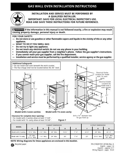
Additional Safeguards<br />
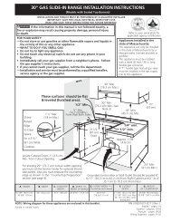
• Do not install wall oven beneath the work counter.<br />
• The flue charge shall not be located below the 36" level.<br />
C<br />
22 5 /16"<br />
19 3 /8"<br />
B<br />
Electrical Outlet<br />
Location for model<br />
with 1½ oven<br />
cavity<br />
42 3 /8"<br />
41 13 /16"<br />
38 7 /16"<br />
23 3 /8"<br />
37 3 /8"<br />
H<br />
F<br />
G<br />
E<br />
Electrical Outlet<br />
Location for<br />
model with 2<br />
oven cavities<br />
18"<br />
27"<br />
A<br />
D<br />
23 17 /32"<br />
21"<br />
23 7 /8" 25 3 /8"<br />
Model with 2 oven cavities<br />
Model with 1½ oven cavity<br />
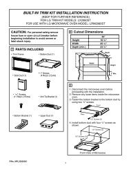
Clearance for complete door opening:<br />
• For model with 2 cavities allow at least 17 5/8".<br />
• For model with 1½ cavity allow at least 19 3/8".<br />
Figure 1<br />
Drill a 1½" diameter hole<br />
for gas hook up<br />
MODEL<br />
CABINET DIMENSIONS<br />
CUTOUT DIMENSIONS<br />
A B C D E F G H<br />
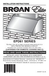
Model with 2 cavities 19 ½" Min. 2 ½" Min. 24" Min. 16 ¾" 7 1 /8" 22 ½" 24" Min. 42 1 /8"<br />
Model with 1 ½ cavity<br />
10" Min.<br />
27 ½" Max.<br />
1 ½" Min. 24" Min. 20" 7 5 /8" 22" 23 ½" Min.<br />
37 ½" Min.<br />
39" Max.<br />
NOTE: Wiring diagrams for these appliances are enclosed in this booklet.<br />
Recycled paper<br />
1<br />
P/N 318201551 (0104) Rev. A<br />
English – pages 1-8<br />
Español – páginas 9-17<br />
Wiring Diagram - pages 18-20
<strong>GAS</strong> <strong>WALL</strong> <strong>OVEN</strong> <strong>INSTALLATION</strong> <strong>INSTRUCTIONS</strong><br />
Important Notes to the Installer<br />
1. Read all instructions contained in these installation<br />
instructions before installing the appliance.<br />
2. Remove all packing material and literature from the<br />
oven and broiler compartments before connecting gas<br />
and electric supply.<br />
3. Observe all governing codes and ordinances.<br />
4. Be sure to leave these instructions with the consumer.<br />
Important Note to the Consumer<br />
Keep these instructions with your Use and Care Guide for<br />
future reference.<br />
Save these instructions for local inspectors.<br />
IMPORTANT SAFETY<br />
<strong>INSTRUCTIONS</strong><br />
POWER FAILURE<br />
Do not attempt to operate the oven in the event<br />
of a power failure. If powwer failure should<br />
occur during operation, turn the oven control to<br />
the OFF position. Failure to turn the oven<br />
control off will result in oven operation upon<br />
resumption of power to the unit.<br />
Installation of these appliances must conform with local<br />
codes or, in the absence of local codes, with the National<br />
Fuel Gas Code ANSI Z223.1—latest edition.<br />
These appliances have been design certified by American<br />
Gas Association (A.G.A.). As with any appliance using<br />
gas and generating heat, there are certain safety<br />
precautions you should follow. You will find them in the<br />
Use and Care Guide, read it carefully.<br />
• Be sure your wall oven is installed and grounded<br />
properly by a qualified installer or service<br />
technician.<br />
• These wall ovens must be electrically grounded in<br />
accordance with local codes or, in their absence,<br />
with the National Electrical Code ANSI/NFPA No.<br />
70—latest edition. See grounding instructions<br />
farther in this manual.<br />
• The installation of appliances designed for<br />
manufactured (mobile) home installation must<br />
conform with Manufactured Home Construction<br />
and Safety Standard Title 24CFR, Part 3280<br />
[Formerly the Federal Standard for Mobile Home<br />
Construction and Safety, Title 24, HUD, (Part 280)]<br />
or when such standard is not applicable the<br />
Standard for Manufactured Home Installation 1982<br />
(Manufactured Home Sites, Communities and Set-<br />
Ups), ANSI Z225.1/NFPA 501-A- latest edition, or<br />
with local codes.<br />
2<br />
Do not store items or food of interest<br />
to children in the cabinets above the appliance.<br />
Children could be seriously burned or injured if they<br />
climb on the appliance to reach these items.<br />
• Do not store or use gasoline or other flammable<br />
vapors and liquids near this or any other<br />
appliance. Explosions or fires could result.<br />
• Be certain all packing materials are removed from the<br />
unit before operating, to prevent fire or smoke damage<br />
should the packing material ignite.<br />
• Do not leave children alone in the kitchen when the<br />
appliance is in use. They should not be allowed to sit<br />
or stand on any part of the appliance, as injury or burns<br />
could result. Keep children from touching the oven<br />
door or glass window when the appliance is operating,<br />
as the door or window could get hot enough to cause<br />
serious burns.<br />
• Remove broiler tray and other utensils from oven<br />
before using the self-clean cycle (if equipped).<br />
• Do not use the oven as a store space. This creates a<br />
potentially hazardous situation.<br />
The appliance requires fresh air for proper burner<br />
combustion. Do not obstruct the flow combustion air at<br />
the oven vent or around the base or beneath the lower<br />
front panel of the appliance. Avoid touching the event<br />
openings or nearby surfaces, as they may become hot.<br />
• Remember, your oven is not designed to heat your<br />
kitchen. Such abuse could result in fire and/or damage<br />
to the unit and will void your warranty.<br />
1. Carpentry<br />
• Refer to figure 1 for the dimensions applicable to your<br />
appliance, and the space necessary to receive the<br />
oven. Corners must be square.<br />
• Floor cabinet must be able to support 150 pounds and<br />
must be flush with bottom of opening.<br />
• Bricked opening (for model with 2 cavities only): If oven<br />
is to be installed in brick or stone, first construct a<br />
rectangular wooden frame with ½" sides and ¼" top<br />
and bottom. The inside dimensions of this frame must<br />
be the same as the opening dimensions in the figure 1.<br />
Place frame flush in brick opening which shall be snug<br />
fit with the outside of frame. Secure frame to brick.<br />
Overhang of oven trim will cover brick and wood and<br />
will not be exposed. Proceed as in "Cabinet<br />
Installation" section farther.
<strong>GAS</strong> <strong>WALL</strong> <strong>OVEN</strong> <strong>INSTALLATION</strong> <strong>INSTRUCTIONS</strong><br />
2. Connect Electricity to Gas Wall<br />
Oven<br />
For personal safety, these appliances must be<br />
properly grounded.<br />
This appliance is equipped with a threeprong<br />
grounding plug for your protection against shock<br />
hazard and must be plugged directly into a properly<br />
grounded receptacle. Do not cut or remove grounding<br />
prong from this plug.<br />
The wall receptacle and circuit should be checked by a<br />
qualified electrician to make sure the receptacle is<br />
properly grounded.<br />
Preferred Method<br />
Grounding<br />
type wall<br />
receptacle<br />
Do not, under any<br />
circumstances, cut,<br />
remove, or bypass<br />
the grounding<br />
prong.<br />
Figure 2<br />
Power supply cord with<br />
3-prong grounding plug<br />
Where a standard 2-prong wall receptacle is installed, it<br />
is the personal responsibility and obligation of the<br />
consumer to have it replaced by a properly grounded 3-<br />
prong wall receptacle.<br />
Do not, under any circumstances, cut or remove the<br />
third (ground) prong from the power cord.<br />
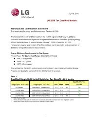
3. Alternate construction<br />
(Model with 1½ oven cavity only)<br />
Installation Instructions for installing a 1½ cavity oven into<br />
an existing 2 cavity opening with dimensions 42 1/8" height<br />
by 22 ½" Width.<br />
1"<br />
42 1 /8"<br />
3"<br />
Figure 3<br />
22 ½"<br />
1. Height adjuster - lower height adjuster 1".<br />
2. If width opening is too wide to secure unit to cabinet<br />
with mounting screws, add filler strips.<br />
3. 2" X 4" (standard 1 ½" X 3 ½") 22" minimum - stand<br />
upright and flush with front cabinet. Secure to floor or<br />
wall.<br />
4. Lower trim (not shown) - overlap cabinet front (at bottom<br />
of cutout ¼" minimum.<br />
2"<br />
If an external electrical source is used, the appliance,<br />
when installed, must be electrically grounded in<br />
accordance with local codes or in their absence of local<br />
codes with the National Electric Code ANSI/NFPA No.<br />
70-1987 or latest edition.<br />
Check all code rules and regulations for connecting the<br />
wall oven to be certain the installation conforms with all<br />
local, municipal and state codes as well as local utility<br />
regulations.<br />
Failure to comply with the above could result in a<br />
serious shock hazard.<br />
Note: All hookups and adjustments shall be performed<br />
by qualified technicians.<br />
Disconnect electrical supply cord from<br />
wall receptacle before servicing wall oven.<br />
3
<strong>GAS</strong> <strong>WALL</strong> <strong>OVEN</strong> <strong>INSTALLATION</strong> <strong>INSTRUCTIONS</strong><br />
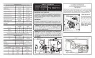
4. Adjusting Oven Height<br />
(Model with 1 ½ oven cavity only)<br />
Remove and lay aside the lower vent decorative trim<br />
that is taped to the side or to the top of the oven. The<br />
decorative trim will be fastened to the lower front of the<br />
oven after it has been installed in the cabinet.<br />
Oven Door<br />
There is a 1 ½" height adjustment on models with<br />
extension panel (see figure 4). With this adjustment and<br />
a ½" trim overhang, a unit can be installed in existing<br />
openings 37 ½" to 39" high.<br />
Oven Bottom<br />
Extension Panel<br />
Figure 5<br />
Figure 4<br />
Adjustment<br />
Holes<br />
Extension Panel<br />
Mounting Screws<br />
To adjust oven height:<br />
1. Lay oven on its back. (see figure 5).<br />
2. Remove the 6 screws that fasten the side extension<br />
panel to the bottom sides of the oven.<br />
3. Move each panel down to the position that increases<br />
the oven height to fit your opening. Each position<br />
changes oven height approximately ½".<br />
4. Line up the appropriate holes in the side extension<br />
panels and sides of the oven. Put the 6 screws back.<br />
5. Proceed with oven installation. Return to upright<br />
position.<br />
5. Cabinet Installation<br />
A. Model With 1½ Oven Cavity<br />
Insert appliance into cutout. Use the 4 mounting screws<br />
provided to fasten the front frame of the appliance to<br />
the cabinet (steps 1 below). Keep the 2 decorative<br />
screws to fix the decorative trim to the cabinet (step 2<br />
below). The mounting holes in the front frame of<br />
appliance may be used as a template to locate the<br />
appliance mounting screw holes on the cabinet.<br />
To fasten the appliance to the cabinet (figure 6):<br />
1. Use 4 mounting screws supplied to secure the<br />
appliance to the cabinetry. 2 holes are located under<br />
the center vent trim on each side, the 2 other holes<br />
are visible when the drawer is opened.<br />
2. Optional: Install the decorative trim under the<br />
appliance (as shown on figure 6) using the 2<br />
decorative screws supplied with the appliance.<br />
Center Vent Trim<br />
Mounting Screws<br />
Decorative Trim<br />
Decorative Screws<br />
Mounting<br />
Screws<br />
Figure 6<br />
4
<strong>GAS</strong> <strong>WALL</strong> <strong>OVEN</strong> <strong>INSTALLATION</strong> <strong>INSTRUCTIONS</strong><br />
B. Model With 2 Oven Cavities<br />
Insert appliance into cutout. The unit must be secured in<br />
place. Use the 2 screws provided in the miscellaneous<br />
parts bag, for mounting the appliance in the mounting<br />
holes on each side trim aside the central vent trim (figure<br />
7).<br />
Remove Screw<br />
Cap<br />
Mounting<br />
Screws<br />
Pipe to be A<br />
tight to flue<br />
collar<br />
B1 Vent Pipe<br />
4” I.D.<br />
4 ½” 0.D.<br />
Figure 8<br />
7. Provide an Adequate Gas Supply<br />
Important: Read these instructions carefully before<br />
connecting this unit to a gas supply.<br />
Figure 7<br />
6. Externally Vented Installations<br />
Model With 2 Oven Cavities only<br />
IMPORTANT: Refer to the serial plate for information on<br />
type of venting, if marked vented, see proper instructions.<br />
NOTE: In some areas, outside venting is required or<br />
preferred. For specified models with outside venting<br />
provided (see specification sheet), use the following<br />
instructions for proper installation of outside venting.<br />
Vent pipe must be mechanically fastened to flue collar.<br />
1. Before the oven is placed in the cabinet opening:<br />
A. Remove knockout on the top cover of the unit and<br />
bend tab up at right angle to the cover.<br />
B. Remove the cap that covers the vent by removing the<br />
screw.<br />
2. Ease the oven into opening.<br />
A. Place the pipe on the vent outlet and drill a 3/32”<br />
diameter hole at point “A” (see figure 8). Hole must<br />
be drilled so that holes in pipe and flue collar line up.<br />
B. Fasten the pipe to flue collar with one screw. (see<br />
figure 8).<br />
In order to fasten pipe to flue collar, it will be necessary<br />
to move control panel out of the way and reach<br />
in to drive screw.<br />
Maintain minimum 1" clearance between the vent pipe<br />
and surrounding combustible surfaces as stated on serial<br />
plate.<br />
The units covered in these instructions are designed to<br />
operate on natural gas at 4" of manifold pressure or on<br />
LP gas at 10" of manifold pressure.<br />
A convertible pressure regulator is connected in series<br />
with the manifold of the wall oven unit and must remain<br />
in series with the supply line, regardless of which type of<br />
gas is being used.<br />
For proper operation, the maximum inlet pressure to<br />
the regulator must not exceed 14" of water column<br />
(W.C.) pressure.<br />
To check the regulator, the inlet pressure must be at<br />
least 1" (or 3.4 kPa) greater than the regulator manifold<br />
pressure setting. If the regulator is set for 4" of manifold<br />
pressure, the inlet pressure must be at least 5". If the<br />
regulator is set for 10", the inlet pressure must be at<br />
least 11".<br />
A manual shut-off valve must be installed on the gas<br />
supply line external to the unit and where it can be<br />
easily reached for the purpose of turning the gas to the<br />
unit on and off.<br />
The gas supply line to the unit should be ½" (1.3 cm) or<br />
¾" (1.9 cm) pipe.<br />
To avoid pilot outage (if applicable) close all openings in<br />
the cabinet cavity that encloses this unit. All openings<br />
around gas service outlets must be closed at the time of<br />
installation.<br />
5
<strong>GAS</strong> <strong>WALL</strong> <strong>OVEN</strong> <strong>INSTALLATION</strong> <strong>INSTRUCTIONS</strong><br />
8. Connection to gas<br />
A. Model with 1 ½ oven cavity (see figure 9)<br />
Pressure Regulator<br />
Shut-Off Valve<br />
BEFORE CONNECTING THE UNIT<br />
Remove all packing material and literature from wall<br />
oven before connecting gas and electrical supply to the<br />
appliance.<br />
If applicable, remove broiler or storage drawer by pulling<br />
drawer out to stops. Lift drawer front to clear stops and<br />
pull out.<br />
Leak testing of the appliance shall be conducted<br />
according to the manufacturer's instructions.<br />
If flexible gas connector is used, gas line must<br />
be A.G.A. design certified.<br />
B. Model with 2 oven cavities (see figure 10)<br />
Oven Safety<br />
Valve<br />
3/8” Nipple<br />
Adaptor or Union<br />
Solid Pipe Or Flex<br />
Connector<br />
External Shut-Off Valve<br />
Figure 9<br />
Pilot Adjustment<br />
(If Equipped)<br />
Pressure Regulator<br />
Shut Off Valve<br />
Support Bracket<br />
Adaptor or Union<br />
External Shut Off Valve *<br />
Figure 10<br />
Shut Off Valve<br />
3/8”<br />
Nipple<br />
IMPORTANT: Prior to attaching gas piping to the oven,<br />
move the shut-off valve support bracket to the left as far<br />
as possible and tighten its mounting screw from<br />
underneath the oven. This keeps the safety valve/<br />
pressure regulator assembly from moving.<br />
Check for leaks. After connecting gas, check system<br />
for leaks with a manometer. If a manometer is not<br />
available shut all pilots off, turn the gas supply on the<br />
unit and use a liquid leak detector at all joints and<br />
connections.<br />
Tighten all connections if necessary to prevent gas<br />
leakage in the wall oven or supply line.<br />
IMPORTANT: A pipe joint sealant resistant to the action<br />
of LP Gas must be used on all pipe connections.<br />
Do not use a flame to check for leaks<br />
from gas connections. Checking for leaks with a flame<br />
may result in a fire or explosion.<br />
Disconnect the oven and its individual shutoff valve<br />
from the gas supply piping system during any pressure<br />
test greater than ½ psig.<br />
Isolate the wall oven from the gas supply piping<br />
system by closing its individual manual shutoff valve<br />
during any pressure testing of the gas supply piping<br />
system at test pressures equal to or less than ½ psig.<br />
9. LP/Propane Gas Conversion<br />
A. Pressure Regulator Conversion<br />
Note: Do not remove the Pressure Regulator.<br />
Convert the Pressure Regulator for use with LP Gas<br />
(see figure 11)<br />
If applicable, remove broiler or storage drawer by<br />
pulling drawer out to stops. Lift drawer front to clear<br />
stops and pull out.<br />
Locate pressure regulator on lower back wall and<br />
convert as shown in figure 11.<br />
A. Remove the cap from the pressure regulator.<br />
B. Remove the plunger.<br />
C. Turn the plunger upside down with the enlarge end<br />
TOWARDS regulator.<br />
D. Replace the plunger inside the regulator. The<br />
letters LP or 10" W.C. should be visible on the<br />
exposed end of the plunger.<br />
E. Replace the cap on the pressure regulator.<br />
NOTE: The type of gas pressure the regulator is set for<br />
is indicated on the top of the plunger.<br />
6
<strong>GAS</strong> <strong>WALL</strong> <strong>OVEN</strong> <strong>INSTALLATION</strong> <strong>INSTRUCTIONS</strong><br />
ENLARGED End<br />
Towards Regulator<br />
For L.P. Gas Figure 11<br />
B. Adjust Oven Burner Orifice<br />
(see figure 12)<br />
Pin<br />
Air Shutter<br />
Oven Burner<br />
Spud<br />
Figure 12<br />
SMALL End Towards<br />
Regulator For<br />
Gasket Natural Gas<br />
L.P.<br />
Nat.<br />
Using a ½" wrench, turn down the adjustable spud<br />
which injects gas into the oven burner. Spud<br />
approximately 2½ turns until snug against the LP<br />
metering pin. Do not overtighten (see figure 12).<br />
Spud<br />
Using a ½" wrench, turn down the adjustable spud<br />
which injects gas into the oven burner. Spud<br />
approximately 2½ turns until snug against the LP<br />
metering pin. Do not overtighten (see figure 13).<br />
10. Natural Gas Conversion<br />
Convert the Pressure Regulator for use with<br />
Natural Gas (see figure 11)<br />
A. Remove the cap from the pressure regulator.<br />
B. Remove the plunger.<br />
C. Turn the plunger upside down with the enlarge end<br />
UP.<br />
D.Replace the plunger inside the regulator. The<br />
letters NAT or 4" W.C. should be visible on the<br />
exposed end of the plunger.<br />
E. Replace the cap on the pressure regulator.<br />
F. Turn the valve hoods approximately 2 1/2 turns<br />
counterclockwise. This will move the hood away<br />
from the mixer pin.<br />
G. Apply gas, adjust pilots and burner air shutter for<br />
proper flame.<br />
H. There should be 4" WC pressure in the manifold<br />
after conversion for proper operation on Natural<br />
Gas.<br />
11. Adjustments<br />
Oven/Broiler Flame Adjustment<br />
The air shutter adjustment is located on the venturi tube,<br />
which sets on the hood of the valve, and is locked in<br />
place with a Phillips head screw. If the air shutter needs<br />
adjusting, loosen the screw and rotate the shutter to<br />
allow more or less air to the burner tube (see figure 14).<br />
C. Adjust Broiler Burner Orifice (Self-Cleaning<br />
Models Only) (see figure 13) Pin<br />
Air Shutter<br />
L.P.<br />
Figure 13<br />
Nat.<br />
Waist-High<br />
Broiler Spud<br />
Spud<br />
Air Adjustment<br />
Shutter<br />
Loosen<br />
Figure 14<br />
For Natural Gas, the air shutter should be approximately<br />
half open. For LP Gas, the air shutter nearly full open.<br />
Too much air will cause the flame to lift awya from the<br />
burner. Too little air will cause the flame to turn yellow<br />
at the outer edges and soot to form.<br />
Remember, the oven will be shipped from the factory set<br />
for Natural Gas, unless otherwise stated. If connecting<br />
to LP gas, be sure to follow procedure under<br />
"Conversion" to change the regulator and burner orifice<br />
to the LP setting.<br />
7
<strong>GAS</strong> <strong>WALL</strong> <strong>OVEN</strong> <strong>INSTALLATION</strong> <strong>INSTRUCTIONS</strong><br />
Observe the oven burner flame to determine if it is right.<br />
It should be steady with a blue cone approximately 1"<br />
and should not extend out over the edges of baffle. For<br />
LP Gas, this will most likely occur when the air<br />
adjustment shutter is completely open (see figure 15).<br />
Turn Oven Temperature to 300°F and allow oven to cycle<br />
on and off.<br />
Model and Serial Number Location<br />
The serial plate is located on the left side inner trim of<br />
the oven for the model with 1 ½ oven cavity and on the<br />
lower oven frame for the model with 2 oven cavities.<br />
When ordering parts for or making inquires about your<br />
wall oven, always be sure to include the model and<br />
serial numbers and a lot number or letter from the serial<br />
plate of your appliance.<br />
Your serial plate also tells you the rating of the burners,<br />
the type of fuel and the pressure the wall oven was<br />
adjusted for when it left the factory.<br />
Stepping, leaning or sitting on the<br />
oven door or drawer can result in serious injuries<br />
and also cause damage to the appliance.<br />
Be sure to keep appliance clear of combustible<br />
materials, gasoline and other flammable vapors and<br />
liquids.<br />
Figure 15<br />
To replace broiler drawer or lower bottom, reverse steps<br />
taken for removal. Replace oven rack and/or broiler<br />
pan.<br />
12. Check Operation<br />
Refer to the Use and Care Guide packaged with the wall<br />
oven for operating instructions and for care and cleaning<br />
of your appliance.<br />
Do not touch the oven burner. They may be hot enough<br />
to cause burns.<br />
1. Check the Igniters (some models)<br />
Operation of electric igniters should be checked after<br />
oven and supply line connectors have been carefully<br />
checked for leaks and oven has been connected to<br />
electric power.<br />
Before You Call for Service<br />
Read the Avoid Service Checklist and operating and<br />
cleaning instructions in your Use and Care Guide.<br />
Check to make sure the house fuse or circuit breaker for<br />
your wall oven is not blown or open.<br />
Care, Cleaning and Maintenance for Wall<br />
Ovens<br />
If removing the wall oven is necessary for cleaning or<br />
maintenance, shut off gas supply. Disconnect the gas<br />
and electric supply. Remove the installation screws from<br />
front frame and lower trim. Pull out only as far as<br />
necessary to disconnect the electric supply line. After<br />
disconnecting the gas and electric supply, finish<br />
removing the unit for servicing and cleaning. Reinstall in<br />
reverse order making sure to level the appliance; check<br />
gas connection for leaks.<br />
2. Oven Igniter System<br />
Close the door and turn the Oven Temperature to<br />
300°F. In approximately 60 seconds, the burner<br />
should ignite and stay on until oven reaches 300°F.<br />
Burner should then cycle on and off to maintain an<br />
average temperature of approximately 300°F.<br />
When All Hookups are Complete<br />
Make sure all controls and programmable timer are left in<br />
the OFF position.<br />
Reset all controls to the "OFF" position after using a<br />
programmable timing operation.<br />
8
INSTRUCCIONES PARA LA INSTALACIÓN HORNO EMPOTRADO A <strong>GAS</strong><br />
LA INSTALACIÓN Y EL SERVICIO DEBEN SER REALIZADOS POR UN<br />
INSTALADOR CALIFICADO.<br />
IMPORTANTE: GUARDE ESTAS INSTRUCCIONES PARA USO DEL<br />
INSPECTOR ELÉCTRICO LOCAL.<br />
LEA Y GUARDE ESTAS INSTRUCCIONES PARA FUTURAS REFERENCIAS<br />
Si todas las instrucciones de éste manual no son observadas a la letra, se puede ocurrir<br />
incendios o explosiones que pueden causar daños materiales, lesiones o la muerte.<br />
PARA SU SEGURIDAD:<br />
— No almacene o utilice gasolina u otros vapores y líquidos inflamables cerca de éste o cualquier otro<br />
artefacto.<br />
— QUE HACER SI HAY FU<strong>GAS</strong> DE <strong>GAS</strong>Æ<br />
• No intente de encender ningún artefacto<br />
• No toque ningún interruptor eléctrico; no utilice ningún aparato telefónico en su edificio.<br />
• Llame inmediatamente el abastecedor de gas desde el teléfono de un vecino. Siga las instrucciones del<br />
abastecedor de gas.<br />
• En caso que no puede contactar el abastecedor de gas llame al departamento de bomberos.<br />
— La instalación y el servicio telefónico deben ser realizados por un instalador calificado, por un servicio<br />
técnico certificado o por el abastecedor de gas.<br />
Medidas de seguridad adicionales<br />
• No instale horno de pared debajo de la mesa de trabajo.<br />
• La salida de descarga no debe estar por debajo de 36" de altura<br />
C<br />
22 5 /16"<br />
19 3 /8"<br />
B<br />
Ubicación de toma de<br />
corriente eléctrica para<br />
modelos con 1 ½”<br />
cavidad de horno<br />
42 3 /8"<br />
41 13 /16"<br />
38 7 /16"<br />
23 3 /8"<br />
37 3 /8"<br />
H<br />
F<br />
G<br />
E<br />
Ubicación de toma de<br />
corriente eléctrica para<br />
modelos con 2 cavidades<br />
de horno.<br />
18"<br />
27"<br />
A<br />
D<br />
23 17 /32"<br />
21"<br />
23 7 /8" 25 3 /8"<br />
Modelos con 2 cavidades de horno. Modelos con 1 ½ cavidad de horno.<br />
Espacio libre para abrir completamente la puerta:<br />
Para modelos con 2 cavidades de horno deje por lo menos 17 5/8”<br />
Para modelos con 1 ½ cavidad de horno deje por lo menos 19 3/8”<br />
Figura 1<br />
Perforación de 1 ½" para<br />
conexión de gas<br />
MODELO<br />
DIMENSIONES DEL ARMARIO<br />
DIMENSIONES DEL HUECO<br />
A B C D E F G H<br />
Modelos con 2 cavidades 19 ½" Mín. 2 ½" Mín. 24" Mín. 16 ¾" 7 1 /8" 22 ½" 24" Mín. 42 1 /8"<br />
Modelos con 1½ cavidad<br />
10" Mín.<br />
27 ½" Máx.<br />
1 ½" Mín. 24" Mín. 20" 7 5 /8" 22" 23 ½" Mín.<br />
NOTA: Se adjunta el diagrama de cables de este horno con el catálogo.<br />
Papel reciclado<br />
9<br />
37 ½" Mín.<br />
39" Máx.<br />
P/N 318201551 (0104) Rev. A<br />
English – pages 1-8<br />
Español – páginas 9-17<br />
Diagrama de la instalación alámbrica - páginas 18-20
INSTRUCCIONNES PARA LA INSTALACIÓN HORNO EMPOTRADO A <strong>GAS</strong><br />
Notas importantes para el instalador:<br />
1. Lea todas las instrucciones de instalación antes de<br />
realizar la instalación de la plancha de cocinar.<br />
2. Retire todos los artículos de embalaje antes de realizar<br />
las conexiones eléctricas a la plancha de cocinar.<br />
3. Observe todos los códigos o reglamentos estatales<br />
4. Asegúrese que el consumidor tenga estas instrucciones.<br />
Notas importantes para el consumidor<br />
Guarde todas las instrucciones con su manual del usuario<br />
para futuras referencias.<br />
INSTRUCCIONES DE<br />
SEGURIDAD IMPORTANTES<br />
CORTE DE ENERGÍA ELÉCTRICA<br />
No trate de usar el horno de encendido eléctrico<br />
durante un corte de energía. En caso de un<br />
corte de energía eléctrica coloque todos los<br />
controles en posición apagado (OFF). El<br />
restablecimiento del servicio eléctrico cuando los<br />
controles del horno están en cualquier posición<br />
diferente a APAGADO causaría el encendido<br />
automático del quemador del horno.<br />
La instalación de este horno empotrado a gas debe<br />
realizarse en conformidad con los códigos locales o, si<br />
estos no existen, con el National Fuel Gas Code ANSI<br />
Z223.1 - última edición.<br />
El diseño de este horno empotrado a gas cuenta con la<br />
aprobación de la American Gas Association (A.G.A.). Al<br />
igual que todos los artefactos a gas que generan calor,<br />
deben seguirse ciertas medidas de seguridad. Vienen con<br />
el Manual del Usuario. Lea atentamente el manual.<br />
• Asegúrese que el horno empotrado sea instalada<br />
y puesta a tierra correctamente por un instalador<br />
o técnico calificado.<br />
• El horno empotrado a gas debe conectarse<br />
eléctricamente a tierra de acuerdo con los códigos<br />
locales o, de no existir, con el código eléctrico<br />
ANSI/NFPA No. 70 - última edición.<br />
• La instalación de unidades diseñadas para casas<br />
(movibles) deben cumplir con los estandares de<br />
“Manufactured Home Construction and Safety Standard,<br />
title 24 CFR part 3280”. Anteriormente “The<br />
Federal Standard for Mobile Home Construction and<br />
Safety title 24. HUD (Part 280)”. O cuando estos<br />
estandares no sean aplicables: “The Standard for<br />
Manufactured Home Installation 1982,<br />
(Manufactured Home Sites, Communities and setups),<br />
ANSI Z225. NFPA - 501 A”, última edición o códigos<br />
y regulaciones locales.<br />
No almacene alimentos u otros objetos<br />
de interés para los niños en alacenas ubicadas<br />
encima de la estufa o en la guarda posterior de<br />
esta. Los niños pueden quemarse o lastimarse<br />
seriamente si se suben en la estufa para alcanzar estos<br />
objetos.<br />
• No guarde o haga uso de gasolina o otros vapores<br />
y líquidos inflamables acerca de esté o cualquier<br />
aparato. Se puede resultar en incendios o<br />
explosiones.<br />
• Asegúrese de remover todo el material de embalaje<br />
del aparato antes de hacerlo funcionar, para evitar<br />
fuego o daños por humo, en caso que el material de<br />
embalaje se encendió.<br />
• No permita que los niños estén solos en la cocina<br />
cuando la estufa esté en uso. No les permita sentarse<br />
o pararse en ninguna parte de la estufa, pues podrían<br />
lastimarse o quemarse. Asegúrese de que no toquen<br />
la puerta del horno o la ventana de vidrio cuando el<br />
horno esté en uso, ya que éstas partes se calientan lo<br />
suficiente como para causar quemaduras serias.<br />
• Remueve la bandeja del asador y otros utensilios antes<br />
de usar el ciclo de limpieza a si mismo.<br />
• No use el horno como espacio de almacenamiento.<br />
Esa situación puede ser peligrosa.<br />
• La estufa requiere aire fresco para que el quemador<br />
haga la combustión adecuadamente. No obstruya la<br />
circulación de aire de combustión en las ventilaciones<br />
del horno, ni alrededor de la base, ni debajo del<br />
tablero frontal de la estufa. Evite tocar las aberturas de<br />
ventilación y las superficies cercanas pues éstas<br />
pueden calentarse.<br />
• Recuerde, su horno no ha sido diseñado para calentar<br />
la cocina. Este abuso puede causar un incendio o daño<br />
de la unidad y anularía la garantía.<br />
1. Carpintería<br />
• Consulte la figura 1 para conocer las dimensiones<br />
pertinentes al modelo de su horno y al espacio<br />
necesario en el que poner el horno. Las esquinas<br />
deben estar cuadradas.<br />
• El piso del gabinete debe soportar una carga de 150<br />
libras y debe estar nivelado con el fondo de la<br />
abertura.<br />
• Abertura en ladrillo (para modelo con 2 cavidades del<br />
mismo tamaño solamente): Si el horno va a ser<br />
empotrado en ladrillo o piedra, construya primero un<br />
marco rectangular de madera de ½" en las laterales y<br />
¼" arriba y abajo. Las dimensiones internas del marco<br />
deben ser iguales a las dimensiones internas del marco<br />
deben ser iguales a las dimensiones del esquema (22<br />
½" X 42 1 /8").<br />
Coloque el marco nivelado y ajustado a la abertura en<br />
el ladrillo. El sobreancho (pestaña) del horno cubrirá el<br />
marco de madera. Proceda como lo muestra el<br />
siguiente esquema.<br />
10
INSTRUCCIONES PARA LA INSTALACIÓN HORNO EMPOTRADO A <strong>GAS</strong><br />
2. Conexión Eléctrica<br />
Como medida de seguridad personal, esté artefacto<br />
debe conectarse a tierra correctamente.<br />
Para su protección contra choques<br />
eléctricos este aparato ha sido equipado con un enchufe<br />
de tres patas con conexión a tierra apropiada. No<br />
remueva la pata redonda de tierra de es enchufe.<br />
3. Alternativa de construccion<br />
(Para modelo con 1 ½ cavidades solamente)<br />
Instrucciones para instalar un horno de 1 ½ cavidades en<br />
una abertura existente para horno de 2 cavidades con<br />
dimensiones de 42 1 /8" de alto por 22 ½" de ancho.<br />
Un electricista calificado debe verificar el enchufe de pared<br />
y el circuito para asegurar que el enchufe está conectado a<br />
tierra correctamente.<br />
42 1 /8"<br />
22 ½"<br />
Método Preferido<br />
Enchure<br />
de pared a<br />
tierra<br />
No debe, bajo<br />
ninguna<br />
circunstancia cortar<br />
o retirar la tercera<br />
pata del cable de<br />
encendido<br />
Figura 2<br />
Cable de encendido con<br />
enchufe de tres<br />
patas a tierra<br />
En caso de encontrarse con un enchufe de pared de dos<br />
patas, es la personal responsabilidad y la obligación del<br />
consumidor reemplazarlo por el enchufe de pared a tierra<br />
de tres patas correspondiente.<br />
No debe, bajo ninguna circunstancia cortar o retirar la<br />
tercera pata (tierra) del cable de encendido<br />
Si una fuente de eléctrica es utilizada; el aparato debe<br />
ser conectado a tierra de acuerdo con las normas locales<br />
o de acuerdo las "National Electrical Code" ANSI/NFPA<br />
No. 70-1987 o ultima edición.<br />
1"<br />
3"<br />
Figura 3<br />
1. Ajuste de altura - ajuste inferior de altura de 1".<br />
2. Si la abertura es demasiado ancha para fijar la unidad<br />
al gabinete con tornillos de montaje, ajuste con las<br />
tiras de relleno.<br />
3. 2" X 4" (1 ½" X 3 ½" standard) 22" mínimo - para al<br />
derecho, nivele con el frente del gabinete. Asegure al<br />
suelo o al pared.<br />
4. Moldura inferior (no se muestra) - monte al menos ¼"<br />
sobre el frente del gabinete (en parte inferior de<br />
abertura).<br />
2"<br />
Verifique todos los códigos, normas o regulaciones para<br />
cerciorarse que la instalación está de acuerdo a los<br />
códigos locales, estatales y de las empresas de servicio<br />
de energía locales.<br />
El incumplimiento las anteriores recomendaciones,<br />
puede resultar en un peligroso coque eléctrico.<br />
Nota: Todas las conexiones y ajustes deben de ser<br />
realizados por un técnico calificado.<br />
Desconecte el cable del suministro<br />
eléctrico del enchufe de pared antes de reparar la<br />
plancha de cocinar.<br />
11
INSTRUCCIONNES PARA LA INSTALACIÓN HORNO EMPOTRADO A <strong>GAS</strong><br />
4. Ajustando la Altura del Horno<br />
(Para modelos con 1 ½ cavidades solamente)<br />
Retire y ponga a un lado la rejilla baja de ventilación que<br />
está pegada a la parte exterior del panel del horno. La<br />
rejilla será fijada a la parte de baja del frente del<br />
gabinete después de que éste haya sido instalado en el<br />
gabinete.<br />
Puerta del horno<br />
Este modelos de horno cuenta con un ajuste de altura de 1<br />
½" (ver figura 4). Con este ajuste y la pestaña de ½" el<br />
horno puede ser instalado en aberturas existentes de 37 ½"<br />
a 39" de altura.<br />
Fondo del<br />
horno<br />
Figura 5<br />
Panel de extensión<br />
Figura 4<br />
Perferaciones<br />
para<br />
ajustar<br />
Panel de<br />
extensión<br />
tornillos de<br />
montaje<br />
Para ajustar la altura del horno:<br />
1. Coloque el horno sobre su parte posterior (ver<br />
figura 5).<br />
2. Remueva los 6 tornillos que aseguran el panel<br />
lateral de extensión a la partes laterales inferiores<br />
del horno.<br />
3. Mueva cada panel hasta la posición que mejor<br />
ajuste la altura del horno al tamaño de su<br />
abertura. Cada posición cambia la altura del<br />
horno aproximadamente ½".<br />
4. Alineé los orificios del panel lateral de extensión<br />
con los de las paredes laterales del horno. Vuelva<br />
a colocar los 6 tornillos.<br />
5. Proceda con la instalación del horno. Vuelva a<br />
colocar el horno sobre su base.<br />
5. Instalación del gabinete<br />
A. Modelo con una cavidad de 1 ½ para el<br />
horno<br />
Introduzca el artefacto en el espacio designado. Use los 4<br />
tornillos para fijar la parte delantera del artefacto al<br />
gabinete (etapa 1 aquí abajo). Guarde los tornilos<br />
decorativos para fijar el marco al gabinete (etapa 2 aquí<br />
abajo). Los hoyos de montage en la parte delantera del<br />
artefacto pueden ser utilizados como referencia para<br />
localizar los hoyos de montaje en el gabinete.<br />
Para ajustar el artefacto al gabinete (figura 6):<br />
1. Utilize los 4 tornilos de montaje para fijar el artefacto<br />
al gabinete. 2 hoyos están localizados bajo el marco de<br />
ventilación a cada lado, los otros 2 hoyos son visibles<br />
cuando la gaveta está abierta.<br />
2. Facultativo: Instale el marco decorativo bajo el<br />
artefacto (como lo muestra la figura 6) utilizando los 2<br />
tornillos decorativos proporcionados con el artefacto.<br />
Marco de ventilación<br />
Tornillos de montaje<br />
Marco<br />
decorativo bajo<br />
Tornillos<br />
de montaje<br />
Tornillos<br />
decorativos<br />
Figura 6<br />
12
INSTRUCCIONES PARA LA INSTALACIÓN HORNO EMPOTRADO A <strong>GAS</strong><br />
B. Modelo con 2 Cavidades<br />
Introduzca el artefacto en el recortado. El<br />
electrodoméstico debe ser sujetado en su lugar. Utilice<br />
los dos tornillos provistos en la bolsa de piezas varias<br />
para montar el electrodoméstico en los orificios de<br />
montaje a cada lado del armazón del horno, por encima<br />
de la puerta (figura 7).<br />
Tornillos de<br />
montaje<br />
Remueva tornillo<br />
Tubo para A<br />
fijar a salida<br />
de ventilacion<br />
Capucha<br />
B1 tubo de<br />
ventilacion<br />
4” I.D.<br />
4 ½” 0.D.<br />
Figura 7<br />
6. Instalaciones ventiladas<br />
exteriormente<br />
Modelo con 2 Cavidades<br />
IMPORTANTE: Refersirse a la placa de la serie para<br />
información en el tipo de ventilación. Si la ventilación está<br />
marcada o especificada, ver las instrucciones pertinentes.<br />
NOTA: En algunas zonas, la ventilación al exterior es<br />
requerida o preferida. Para modelos especificados con<br />
ventilación al exterior (ver hoja de especificaciones). Use<br />
las siguientes instrucciones para una correcta instalación de<br />
la ventilación al exterior. El tubo de ventilación debe estar<br />
mecánicamente amarrado al collar de salida. Ver detalle.<br />
1. Antes de colocar el horno en la abertura:<br />
A. Remueva el destapadero de la parte alta de la<br />
cubierta y doble la pestaña en ángulo recto con<br />
respecto a la cubierta.<br />
B. Remueva la tapa que proteje la ventilación quitando<br />
el tornillo.<br />
2. Deslice el horno la abertura:<br />
A. Coloque el tubo en la salida de la ventilación y<br />
taladre un hueco de 3/32” de diámetro en el punto<br />
“A” (ver figura 8). La perforación en el tubo debe<br />
ser hecha de manera que coincida con la de la salida<br />
de la ventilación.<br />
B. Ajuste la tubería de ventilación a la salida de ventilación<br />
con un tornillo (ver figura 8).<br />
Para ajustar el tubo a la salida es necesario remover<br />
el panel de controles para poder alcanzar el tornillo.<br />
Guarde al menos 1" de margen libre entre la tubería de<br />
ventilación y los elementos combustibles vecinos (como lo<br />
establece la placa de serie)<br />
13<br />
Figura 8<br />
7. Provea un adecuado suministro de gas<br />
Importante: Lea estas instrucciones cuidadosamente<br />
antes de conectar esta unidad al suministro de gas.<br />
Las unidades a las cuales se refieren estas instrucciones<br />
han sido diseñadas para operar con gas natural de 4"<br />
WC o gas LP de 10" WC.<br />
Se conecta un regulador convertible de presión en serie al<br />
múltiple de el horno empotrado y debe permanecer en<br />
serie con la línea de suministro de gas,<br />
independientemente del tipo de gas que se esté usando.<br />
Para que manejo correcto, la presión de entrada<br />
máxima hacia el regulador no debe exceder 14" (W.C.)<br />
de presión de la columna de agua.<br />
Para controlar el regulador, la presión de entrada debe ser<br />
de al menos 1" (o 3.4 Kpa) mayor que el ajuste de la<br />
presión del múltiple del regulador. El regulador se ajusta a<br />
4" de la presión del múltiple, la presión de entrada debe<br />
de ser de al menos 5". El regulador se ajusta a 10" de la<br />
presión del múltiple, la presión de entrada debe de ser de<br />
al menos 11".<br />
Una válvula de corte manual externa a la unidad debe<br />
instalarse en la línea de suministro de gas. El propósito<br />
de esta válvula es poder abrir o cerrar al suministro de<br />
gas a la unidad. Esta válvula debe estar localizada en<br />
un sitio de fácil acceso para cerrar el suministro de gas a<br />
la unidad.<br />
La línea de suministro de gas por el plancha de cocinar<br />
debería tener un tubo de ½" o de ¾".
INSTRUCCIONNES PARA LA INSTALACIÓN HORNO EMPOTRADO A <strong>GAS</strong><br />
Para evitar que el piloto se apague (si puede aplicarse),<br />
cierre todas las aberturas de la cavidad del gabinete que<br />
encierra la unida. También cualquier abertura alrededor<br />
de las salidas del servicio de gas deben estar cerrados en<br />
el momento de la instalación.<br />
8. Conexión del gas<br />
A. Modelo con 1 ½ cavidades (vea figura 9)<br />
Regulador de presion<br />
3/8” Niple<br />
Adaptor o Union<br />
Tubería rigida o<br />
conector flexible<br />
Valvula exterior de cierre<br />
Figura 9<br />
Si se utiliza conectador de gas flexible, la línea<br />
de gas deberá ser de diseño A.G.A. certificado.<br />
B. Modelo con 2 cavidades (vea figura 10)<br />
Adjuste de piloto (Si puede aplicarse)<br />
Regulador de presión<br />
Valvula de seguridad Platina de<br />
soporte de la<br />
válvula de cierre<br />
Valvula de cierre<br />
Válvula de cierre<br />
3/8”<br />
Niple<br />
IMPORTANTE: Antes de conectar la tuberia de gas al<br />
horno mueva la platina de soporte de la valvula de cierre<br />
completamente hacia la izquierda y apriete el tornillo<br />
que la sostiene desde debajo del horno. Esto asegura<br />
que el ensamblaje del regulador de presion de la valvula<br />
de seguridad no se mueva.<br />
ANTES DE CONNECTAR ESTA UNIDAD<br />
Retire todos los artículos de embalaje y folletos de el<br />
horno empotrado antes de realizar las conexiones de gas<br />
y eléctricas a el horno.<br />
Si necesario, remueva al asador o el cajón de<br />
almacenamiento hallándolo hacia afuera hasta los topes,<br />
luego saque hacia afuera.<br />
Verificar si hay fugas en el electrodoméstico, la<br />
verificación debe de ser realizada según las instrucciones<br />
del fabricante.<br />
Verifique si hay fugas. Luego de conectar la cocina al<br />
gas, verifique el sistema con un manómetro. Si no cuenta<br />
con éste instrumento, dé la vuelta al suministro de gas de<br />
la cocina y utilice un detector de fugas líquidas (o agua y<br />
jabón) en todas las articulaciones y conexiones para<br />
verificar si existen fugas.<br />
Ajuste todas las conexiones en caso que sea necesario,<br />
para evitar fugas de gas en la cocina o en el tubo de<br />
suministro de gas<br />
IMPORTANTE: Para las uniones de tubería debe usarse<br />
un sellante de unión de tubería que sea resistente a la<br />
acción del gas LP.<br />
No use ningún tipo de llama para<br />
verificar si hay fugas de gas. Verifique si hay fugas con<br />
una llama puede ocasionar incendio o explosión.<br />
Desconecte el horno y su válvula de cierre individual<br />
del sistema de tubería del suministro de gas durante<br />
cualquier ensayo de presión del sistema en ensayos de<br />
presión superiores a 1/2 psig (3.5 kPa o 14" colomna de<br />
agua).<br />
Aparte el horno del sistema de tubería del suministro<br />
de gas cierrando su válvula de cierre individual manual,<br />
durante cualquier ensayo de presión del sistema de<br />
suministro de gas en ensayos iguales o inferiores a 1/2 psig<br />
(3.5 kPa o 14" colomna de agua).<br />
Adaptor o Unión<br />
Válvula de corte manual externa<br />
Figure 10<br />
14
INSTRUCCIONES PARA LA INSTALACIÓN HORNO EMPOTRADO A <strong>GAS</strong><br />
9. Conversión de Gas Propano/<br />
Licuado<br />
A. Conversión del regulador de presión<br />
Nota: No remueva el regulador de presión.<br />
Convertir el regulador de presión para que se<br />
pueda usar con Gas LP/Propano (vea figura 11)<br />
Si necesario, remueva al asador o el cajón de<br />
almacenamiento hallándolo hacia afuera hasta<br />
los topes, luego saque hacia afuera.<br />
Localice el regulador de presión en la parte<br />
inferior de la pared trasera y modifique como se<br />
muestra en la figura 11.<br />
A. Remueva la tapa del regulador de presión.<br />
B. Remueva el pistón de la tapa.<br />
C. Dé la vuelta al pistón, poniendo la GRANDE<br />
extremidad hacia el regulador.<br />
D. Vuelva a poner el pistón dentro de la tapa.<br />
Las letras LP o 10" W.C. deben de estar<br />
visibles en la extremidad descubierta del<br />
pistón.<br />
E. Vuelva a poner la tapa del regulador.<br />
NOTA: El tipo de presión de gas para el cual ha<br />
sido calibrado el regulador esta indicado en la<br />
parte superior del pistón.<br />
Junta<br />
PEQUEÑA<br />
extremidad hacia el<br />
regulador para gas<br />
natural<br />
B. Ajuste del orificio del quemador del horno<br />
(vea figura 12)<br />
Obturador de aire<br />
Junta en forma de<br />
bellota del quemador<br />
Figura 12<br />
Pasador<br />
L.P.<br />
Nat.<br />
Junta en<br />
forma<br />
bellota<br />
Usando una llave de ½", giro hacia abajo la junta en<br />
forma de bellota ajustable que inyecta gas al quemador<br />
del horno. Gire esta junta en forma de bellota hasta que<br />
ajuste contra el pasador medidor de LP. Esto será<br />
aproximadamente 2 ½ vueltas. No lo apriete demasiado<br />
(vea figura 12).<br />
C. Ajuste del orificio del quemador del<br />
asador (Modelos autolimpiadores solamente) (vea<br />
figura 13)<br />
Pasador<br />
L.P.<br />
Nat.<br />
GRANDE extremidad<br />
hacia el regulador<br />
para Gas L.P.<br />
Figura 11<br />
Obturador de aire<br />
Junta en<br />
forma de<br />
bellota<br />
Junta en forma<br />
de bellota de la<br />
parilla<br />
Figura 13<br />
Usando una llave de ½", giro hacia abajo la junta en<br />
forma de bellota ajustable que inyecta gas al quemador<br />
del horno. Gire esta junta en forma de bellota hasta que<br />
ajuste contra el pasador medidor de LP. Esto será<br />
aproximadamente 2 ½ vueltas. No lo apriete demasiado<br />
(vea figura 13).<br />
15
INSTRUCCIONNES PARA LA INSTALACIÓN HORNO EMPOTRADO A <strong>GAS</strong><br />
10. Conversión de Gas Natural<br />
Convertir la unidad de Gas LP/Propano a Gas<br />
Natural, proceda de la siguiente manerar (vea<br />
figura 11)<br />
A. Remueva la tapa del regulador de presión.<br />
B. Remueva el desatascador.<br />
C. Gire el desatascador hacia arriba con el lado<br />
grande hacia arriba.<br />
D. Ponga el desatascador entre el regulador. Las<br />
letras NAT o 4" WC deberan estar a la vista<br />
en la parte expuesta del desatascador.<br />
E. Colique la tapa en el vegulador.<br />
F. Gire la capucha de la válvula<br />
aproximadamente 2 1/2 vueltas en el sentido<br />
contrario a las manecillas del reloj. Esto<br />
separará la capucha del pasador mezclador.<br />
G. Pase gas, ajuste los pilotos y el quemador<br />
para obtener una llama conveniente.<br />
H. Debera haber 4" WC de presión en el<br />
multiple después de este cambio para operar<br />
propiamente con gas natural.<br />
Use un manómetro para chequear la presión en<br />
el multiple, Si hay alguna duda. Recuerde la<br />
presión de entrada debe ser al menos 1" WC más<br />
alta que la presión de salida. La presión de<br />
entrada en el regulador nunca debe exceder 14"<br />
WC.<br />
Para gas natural la entrada de aire deberá estar<br />
aproximadamente medio abierta. Para gas LP la entrada<br />
de aire deberá estar casi totalmente abierta.<br />
Demasiado aire haría que la llama se alejara del<br />
quemador. Una entrada insuficiente de aire causaría la<br />
coloración amarilla del borde externo de la llama yla<br />
formación de hollín.<br />
Recuerde, el horno será despacho de la fábrica<br />
preparado para trabajar con gas natural, a menos que se<br />
especifique algo diferente. Si se va a conectar a LP G35<br />
asegúrese de seguir el procedimiento indicado en<br />
"Conversión" para cambiar el regulador y el orificio del<br />
quemador a la ubicación LP.<br />
Para determinar si la llama del quemador del horno es la<br />
apropiada, observe la llama. Esta debe estar estable<br />
formando conos azules de 1" aproximadamente. La<br />
llama no debe extenderse por encima de los bordes del<br />
resonador. Para gas LP, ésto ocurre más frecuentemente<br />
cuando el obturador de ajuste de aire está<br />
completamente abierto (vea figura 15).<br />
Ponga el botón de <strong>OVEN</strong> TEMP (temperatura del horno)<br />
en 300°F, y permita que el horno alterne entre "ON" y<br />
"OFF" (prendido y apago).<br />
11. Ajuste del la llama del quemador<br />
del horno/asador<br />
Ajuste el obturador de aire. Esté localizado en el<br />
vénturi, jundo a la capucha de la válvula y es fijado en<br />
su lugar por un tornillo con cabeza tipo Phillips. Si éste<br />
necesita ajuste, afloje el tornillo y rota el obturador para<br />
permitir más o menos aire en el tubo del quemador.<br />
(vea figura 14).<br />
Obturador de<br />
aire<br />
Flojo<br />
Figura 15<br />
Para volver a colocar el cajón o el fondo inferior del<br />
asador, siga en forma inversa los pasos tomados para<br />
retirarlo. Vuelva a colocar la parrilla del horno y/o la<br />
bandeja del asador.<br />
Figura 14<br />
16
INSTRUCCIONES PARA LA INSTALACIÓN HORNO EMPOTRADO A <strong>GAS</strong><br />
12. Verifique la operación<br />
Refiera al Manual del Usuario que viene con el horno<br />
empotrado para las instrucciones de funcionamiento y el<br />
mantenimiento y la limpieza de su horno empotrado.<br />
No toque a los quemadores. Pueden estar<br />
suficientemente calientes par causar quemaduras.<br />
1. Verifique los dispositivos de encendido<br />
(algunos modelos)<br />
La manipulación de los dispositivos de encendido<br />
eléctrico deberá verificarse tras haber revisado<br />
detenidamente el horno y los conectores del tubo del<br />
suministro de fugas y tras haber conectado el horno al<br />
suministro eléctrico.<br />
2. Sistema de encendido del horno<br />
Cierre la puerta del horno y gire el botón de <strong>OVEN</strong> TEMP<br />
(temperatura del horno) a 300°F. En 60 segundos<br />
aproximadamente, el quemador debe prender y<br />
permanecer encendido hasta que el horno alcance<br />
300°F. El quemador seguirá alternando entre encendido<br />
y apago para mantener una temperatura promedia de<br />
aproximadamente 300°F.<br />
Cuando se han realizado todos los sistema<br />
de conexión<br />
Asegúrese que todos los controles están en la posición de<br />
OFF (apagado).<br />
Vuelva a colocar todos los controles en la posición de<br />
"OFF" (apagado) después de utilizar el functionamiento de<br />
programación cronometrada.<br />
Modelo y ubicación del número de serie<br />
La placa de serie está ubicada al interior del contramarco<br />
izquierdo del horno para modelos con 1 ½ cavidad de<br />
horno y en el armazón de bajo del horno para modelos con<br />
2 cavidades de horno.<br />
Asegúrese de incluir el modelo, número de serie y el<br />
número o letra de lote que se encuentran en la placa,<br />
en todo pedido de partes o solicitud de información<br />
acerca de su horno empotrado.<br />
La placa de número de serie también indica las<br />
especificaciones de los quemadores, el tipo de<br />
combustible y la presión para la cual fué ajustada el<br />
horno empotrado en la fábrica.<br />
El apoyarse, pisarse o sentarse en<br />
la puerta o en la gaveta de este horno puede<br />
ocasionar graves heridas y también daños a la<br />
plancha de cocinar.<br />
Asegúrese de no almanecer sobre o dentro el aparato<br />
materiales inflamables, gasolina y otros líquidos<br />
inflamables o latas en aerosol.<br />
Antes de llamar al servicio técnico<br />
Lea la lista titulada "Evitando Llamadas de Servicio" y<br />
las instrucciones de functionamiento en su Manual del<br />
Usuario.<br />
Verifique que los fusibles de la casa no se hayan fundido<br />
o el cortocircuito del horno no haya saltado o abierto.<br />
Cuidado, limpieza y mantenimiento<br />
Cierre el suministro de gas en caso de ser necesario<br />
remover la unidad para su limpieza o reparación.<br />
Desconecte la línea de suministro de gas. Remueva los<br />
tornillos de instalación del marco frontal y la parrilla<br />
inferior. Hale hacia afuera apenas lo necesario para<br />
poder desconectar del toma eléctrico. Después de<br />
desconectar del suministro eléctrico y de gas, termine de<br />
remover la unidad para su limpieza o mantenimiento.<br />
Reinstale siguiendo el procedimiento inverso. Asegúrese<br />
de nivelar la estufa y verificar que no halla escapes en la<br />
conexión de gas.<br />
17
WIRING DIAGRAM - DIAGRAMA DE LA INSTALACIÓN ALÁMBRICA<br />
(For Models with 2 Oven Cavities - Para modelo con 2 cavidades)<br />
18
WIRING DIAGRAM - DIAGRAMA DE LA INSTALACIÓN ALÁMBRICA<br />
(For Easy Clean Models with 1 ½ Oven Cavity - Para modelos fácilmente limpiables con 1½ cavidad)<br />
19
WIRING DIAGRAM - DIAGRAMA DE LA INSTALACIÓN ALÁMBRICA<br />
(For Self-Clean Models with 1 ½ Oven Cavity - Para modelos auto-limpiables con 1½ cavidad)<br />
20