TIEMPO/CEILING FAN TIEMPO/VENTILADOR DE TECHO ... - Lowe's
TIEMPO/CEILING FAN TIEMPO/VENTILADOR DE TECHO ... - Lowe's
TIEMPO/CEILING FAN TIEMPO/VENTILADOR DE TECHO ... - Lowe's

Create successful ePaper yourself
Turn your PDF publications into a flip-book with our unique Google optimized e-Paper software.
Harbor Breeze® is aregistered trademark<br />
of LF, LLC. All Rights Reserved.<br />
ITEM/ARTICULO #0125453<br />
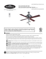
<strong>TIEMPO</strong>/<strong>CEILING</strong> <strong>FAN</strong><br />
<strong>TIEMPO</strong>/<strong>VENTILADOR</strong> <strong>DE</strong> <strong>TECHO</strong> (página 11)<br />
MO<strong>DE</strong>L/MO<strong>DE</strong>LO #E-TM52BNK5CS<br />
Federal regulations require ceiling fans with light kits manufactured or imported after<br />
January 1, 2009, to limit total wattage consumed by the light kit to 190W. Therefore,<br />
this fan is equipped with a wattage limiting device. If you lamp this fan's light kit with<br />
bulbs totaling more than 190W, the wattage limiting device will reduce the watts<br />
consumed to 190W.<br />
WARNINGS<br />
E192641<br />
• Read and save these instructions.<br />
• Read this manual carefully and completely before attempting to assemble, install or operate this product.<br />
• Be sure you read and understand the Safety Information on page 3 of these instructions.<br />
• Do not discard fan carton or foam inserts. Should this fan need to be returned to the factory for repairs, it must be<br />
shipped in its original packaging to ensure proper protection against damage that might exceed the initial cause for<br />
return.<br />
• CAUTION: Before proceeding, be sure to shut off electricity at main switch or circuit breaker in order to avoid<br />
electrical shock.<br />
• WARNING: To reduce the risk of fire or electric shock, do not use this fan with variable speed switch.<br />
• WARNING: To reduce the risk of fire, electric shock, or personal injury, do not bend the blade arms when<br />
installing them, balancing the blades, or cleaning the fan. Do not insert foreign objects between the rotating fan<br />
blades. Mount to outlet box marked "ACCEPTABLE FOR <strong>FAN</strong> SUPPORT" and use mounting screws provided with<br />
the outlet box. Most outlet boxes commonly used for the support of lighting fixtures are not acceptable for fan<br />
support and may need to be replaced. Consult a qualified electrician if in doubt.<br />
Questions, problems, missing parts Before returning to your retailer, call or contact our customer service<br />
department at 1-800-527-1292, 8:30 a.m.-5:00 p.m., CST, Monday-Friday.
Harbor Breeze® is a registered trademark<br />
of LF, LLC. All Rights Reserved.<br />
ITEM/ARTICULO #0125500<br />
<strong>TIEMPO</strong>/<strong>CEILING</strong> <strong>FAN</strong><br />
<strong>TIEMPO</strong>/<strong>VENTILADOR</strong> <strong>DE</strong> <strong>TECHO</strong> (página 11)<br />
MO<strong>DE</strong>L/MO<strong>DE</strong>LO #E-TM52BNKB5CS<br />
Federal regulations require ceiling fans with light kits manufactured or imported after<br />
January 1, 2009, to limit total wattage consumed by the light kit to 190W. Therefore,<br />
this fan is equipped with a wattage limiting device. If you lamp this fan's light kit with<br />
bulbs totaling more than 190W, the wattage limiting device will reduce the watts<br />
consumed to 190W.<br />
WARNINGS<br />
E192641<br />
• Read and save these instructions.<br />
• Read this manual carefully and completely before attempting to assemble, install or operate this product.<br />
• Be sure you read and understand the Safety Information on page 3 of these instructions.<br />
• Do not discard fan carton or foam inserts. Should this fan need to be returned to the factory for repairs, it must be<br />
shipped in its original packaging to ensure proper protection against damage that might exceed the initial cause for<br />
return.<br />
• CAUTION: Before proceeding, be sure to shut off electricity at main switch or circuit breaker in order to avoid<br />
electrical shock.<br />
• WARNING: To reduce the risk of fire or electric shock, do not use this fan with variable speed switch.<br />
• WARNING: To reduce the risk of fire, electric shock, or personal injury, do not bend the blade arms when<br />
installing them, balancing the blades, or cleaning the fan. Do not insert foreign objects between the rotating fan<br />
blades. Mount to outlet box marked "ACCEPTABLE FOR <strong>FAN</strong> SUPPORT" and use mounting screws provided with<br />
the outlet box. Most outlet boxes commonly used for the support of lighting fixtures are not acceptable for fan<br />
support and may need to be replaced. Consult a qualified electrician if in doubt.<br />
Questions, problems, missing parts Before returning to your retailer, call or contact our customer service<br />
department at 1-800-527-1292, 8:30 a.m.-5:00 p.m., CST, Monday-Friday.
Harbor Breeze® is a registered trademark<br />
of LF, LLC. All Rights Reserved.<br />
ITEM/ARTICULO #0126663<br />
<strong>TIEMPO</strong>/<strong>CEILING</strong> <strong>FAN</strong><br />
<strong>TIEMPO</strong>/<strong>VENTILADOR</strong> <strong>DE</strong> <strong>TECHO</strong> (página 11)<br />
MO<strong>DE</strong>L/MO<strong>DE</strong>LO #E-TM52BNKR5CS<br />
Federal regulations require ceiling fans with light kits manufactured or imported after<br />
January 1, 2009, to limit total wattage consumed by the light kit to 190W. Therefore,<br />
this fan is equipped with a wattage limiting device. If you lamp this fan's light kit with<br />
bulbs totaling more than 190W, the wattage limiting device will reduce the watts<br />
consumed to 190W.<br />
WARNINGS<br />
E192641<br />
• Read and save these instructions.<br />
• Read this manual carefully and completely before attempting to assemble, install or operate this product.<br />
• Be sure you read and understand the Safety Information on page 3 of these instructions.<br />
• Do not discard fan carton or foam inserts. Should this fan need to be returned to the factory for repairs, it must be<br />
shipped in its original packaging to ensure proper protection against damage that might exceed the initial cause for<br />
return.<br />
• CAUTION: Before proceeding, be sure to shut off electricity at main switch or circuit breaker in order to avoid<br />
electrical shock.<br />
• WARNING: To reduce the risk of fire or electric shock, do not use this fan with variable speed switch.<br />
• WARNING: To reduce the risk of fire, electric shock, or personal injury, do not bend the blade arms when<br />
installing them, balancing the blades, or cleaning the fan. Do not insert foreign objects between the rotating fan<br />
blades. Mount to outlet box marked "ACCEPTABLE FOR <strong>FAN</strong> SUPPORT" and use mounting screws provided with<br />
the outlet box. Most outlet boxes commonly used for the support of lighting fixtures are not acceptable for fan<br />
support and may need to be replaced. Consult a qualified electrician if in doubt.<br />
Questions, problems, missing parts Before returning to your retailer, call or contact our customer service<br />
department at 1-800-527-1292, 8:30 a.m.-5:00 p.m., CST, Monday-Friday.
TABLE OF CONTENTS<br />
Safety Information<br />
Package Contents<br />
Preparation<br />
Initial Installation<br />
Fan Mounting<br />
........................…………………………………………………………………………...……..….3<br />
.............................…………………………………………………………………..……..…..…..4<br />
.......................................….…………………..……………………….…………….………………....5<br />
............................................……………………...…………………………………………...….5<br />
........................…………………………....…………………………................................................6<br />
Wiring .........................................................................................................……………………………….......6 - 7<br />
Final Installation ............………………….…………….……………………….………….....….…....................7 - 8<br />
Fan Operation<br />
............................................................................................…………………………………....….8<br />
Care and Maintenance<br />
Troubleshooting<br />
.......................………………………………………………………………..…………….…9<br />
...........................................………...………………………….……………..………....……..…...9<br />
Warranty ........................…………………………………….…………………………………………..…………..…. 10<br />
2
SAFETY INFORMATION<br />
READ AND SAVE THESE INSTRUCTIONS<br />
Please read and understand this entire manual before attempting to assemble, install or operate the product. If you<br />
have any questions regarding the product, please call customer service at 1-800-527-1292, 8:30 a.m.-5:00 p.m.,<br />
CST, Monday-Friday.<br />
1. Before you begin installing the fan, disconnect the power by removing fuses or turning off circuit breakers.<br />
2. CAUTION: Read all instructions and safety information before installing your new fan. Review the<br />
accompanying assembly diagrams.<br />
3. CAUTION: To avoid personal injury, the use of gloves may be necessary while handling fan parts with<br />
sharp edges.<br />
4. Make sure that all electrical connections comply with local codes, ordinances, the National Electrical Code and<br />
ANSI/NFPA 70-1999. Hire a qualified electrician or consult a do-it-yourself wiring handbook, available at <strong>Lowe's</strong>, if<br />
you are unfamiliar with installing electrical wiring.<br />
5. Make sure the installation site you choose allows a minimum clearance of 7 feet from the blades to the floor and at<br />
least 30 in. from the end of the blades to any obstruction.<br />
6. WARNING: To reduce the risk of fire, electrical shock, or personal injury, mount fan to outlet box marked<br />
"ACCEPTABLE FOR <strong>FAN</strong> SUPPORT OF 15.9 KG (35 LBS) OR LESS" and use mounting screws provided with the<br />
outlet box. Most outlet boxes commonly used for the support of lighting fixtures are not acceptable for fan support<br />
and may need to be replaced. Consult a qualified electrician if in doubt. Secure the outlet box directly to the building<br />
structure. The outlet box and its support must be able to support the moving weight of the fan (at least 35 lbs.). Do<br />
NOT use a plastic outlet box.<br />
7. After you install the fan, make sure that all connections are secure to prevent the fan from falling.<br />
8. WARNING: To reduce the risk of fire, electrical shock, or personal injury, wire connectors provided with this<br />
fan are designed to accept only one 12 gauge house wire and two lead wires from the fan. If your house wire is<br />
larger than 12 gauge or there is more than one house wire to connect to the two fan lead wires, consult an<br />
electrician for the proper size wire connectors to use.<br />
9. WARNING: To reduce the risk of fire or electrical shock, do not use the fan with any solid state speed<br />
control device or control fan speed with a full range dimmer switch.<br />
10. WARNING: To reduce the risk of fire, electrical shock, or personal injury, do not bend the blade arms when<br />
installing them, balancing the blades, or cleaning the fan. Do not insert objects between the rotating fan blades.<br />
11. WARNING: To reduce the risk of personal injury, use only parts provided with this fan. The use of parts<br />
OTHER than those provided with this fan will void the warranty.<br />
12. The net weight of this fan including the light kit is: 24.25 lbs. (11 kg).<br />
3
PACKAGE CONTENTS<br />
Part Description Quantity<br />
A<br />
B<br />
C<br />
D*<br />
E<br />
F<br />
G<br />
H<br />
I<br />
J<br />
K<br />
Downrod<br />
1<br />
Canopy<br />
1<br />
Mounting Bracket<br />
1<br />
Motor Housing<br />
1<br />
Light Kit Fitter<br />
1<br />
Yoke Cover<br />
1<br />
Switch Housing Plate<br />
1<br />
Blade Arm<br />
5<br />
Blade<br />
5<br />
Glass Shade<br />
4<br />
Motor Screw (in motor)<br />
10<br />
A B C<br />
D E F<br />
L<br />
3/16 Blade Screw (in hardware pack)<br />
15<br />
M*<br />
Candelabra Base Bulb<br />
4<br />
G<br />
H<br />
I<br />
N<br />
5.4M/M Lock Washer (in motor)<br />
10<br />
O<br />
Blade Washer (in hardware pack)<br />
15<br />
P<br />
E3 Wire Connector (in hardware pack)<br />
4<br />
Q<br />
Canopy Mounting Screw (attached to mounting bracket)<br />
4<br />
R<br />
S<br />
Pin (in motor housing yoke)<br />
Clip (attached to pin)<br />
1<br />
1<br />
J<br />
K<br />
L<br />
T<br />
Pull Chain Extension (in hardware pack)<br />
2<br />
U<br />
Canopy cover (in hardware pack)<br />
1<br />
IMPORTANT REMIN<strong>DE</strong>R: You must use<br />
the parts provided with this fan for proper<br />
installation and safety.<br />
M N O<br />
P Q R<br />
S T U<br />
NOTE:<br />
For replacement parts, call our customer service department<br />
at 1-800-527-1292, 8:30 a.m.-5:00 p.m., CST, Monday-Friday.<br />
When ordering parts, please have the Model # or Item # of the<br />
fan available, which can be found on page 1.<br />
* The part denoted with an asterisk (*) above is NOT replaceable.<br />
4
PREPARATION<br />
1. Before beginning assembly and installation of product, make sure all parts are present. Compare parts with<br />
"Package Contents" list and diagrams on the previous page. If any part is missing or damaged, do not attempt to<br />
assemble, install or operate the product. Contact customer service for replacement parts as indicated at the bottom<br />
of page 4.<br />
Estimated Assembly Time: 120 minutes<br />
Tools Required for Assembly (not included): electrical tape, Phillips screwdriver, pliers, safety glasses, stepladder<br />
and wire strippers<br />
Helpful Tools (not included): AC tester light, tape measure, do-it-yourself-guide and wire cutters<br />
Bulbs Required (included): 4 candelabra base 40 watt max. bulbs<br />
DANGER: When using an existing outlet box, make sure the box is securely attached to the building<br />
structure and can support the full weight of the fan. Failure to do this can result in serious injury or death.<br />
2. After opening top of carton, remove mounting hardware package from foam inserts. Remove motor from packing<br />
and place on carpet or on foam to avoid damage to finish.<br />
CAUTION: Carefully check all screws, bolts and nuts on fan motor assembly to ensure that they are secured.<br />
INITIAL INSTALLATION<br />
1. Turn off circuit breakers and wall switch to the fan supply line<br />
leads. [Fig. 1]<br />
DANGER: Failure to disconnect power supply prior to<br />
installation may result in serious injury or death.<br />
Fig. 1<br />
2. Determine mounting method to use. [Fig. 2]<br />
A. Normal mount<br />
B. Angle mount<br />
Important: If using the angle mount, check to make sure the<br />
ceiling angle is not steeper than 19°.<br />
Fig. 2<br />
A<br />
B<br />
3. Check to make sure blades (I) are at least 30 in. from any<br />
obstruction. Check downrod (A) length to ensure blades (I) are at<br />
least 7 ft. above the floor. [Fig. 3]<br />
7 ft.<br />
min.<br />
I<br />
30 in.<br />
min.<br />
Fig. 3<br />
4. Secure mounting bracket (C) to outlet box using screws, spring<br />
washers, and flat washers provided with the outlet box. [Fig. 4]<br />
*Note: It is very important that you use the proper hardware when<br />
installing the mounting bracket (C) as this will support the fan.<br />
C<br />
Important: If using the angle mount, make sure open end of<br />
mounting bracket (C) is installed facing the higher point of the<br />
ceiling.<br />
Fig. 4<br />
5. Remove motor screws (K) and lock washers (N) from underside<br />
of motor. If necessary, discard plastic pieces. [Fig. 5]<br />
Fig. 5<br />
N K<br />
D<br />
5
<strong>FAN</strong> MOUNTING<br />
1. Insert downrod (A) through canopy (B) and yoke cover (F). Thread wires from<br />
motor housing (D) through downrod (A). [Fig. 1]<br />
*Helpful Hint: Downrod style mounting is best suited for ceilings 8 ft. (2.44 m)<br />
high or higher. For taller ceilings you may want to use a longer downrod (not<br />
included). Angle style mounting is best suited for angled or vaulted ceilings. A<br />
longer downrod is sometimes necessary to ensure proper blade clearance.<br />
Fig. 1<br />
B<br />
A<br />
F<br />
2. Insert downrod (A) through canopy (B), canopy cover (U), and yoke cover<br />
(F). [Note: Canopy cover (U) must be turned with the shiny side toward the<br />
motor housing (D).] Thread wires from motor housing (D) through downrod (A).<br />
[Fig. 2] Remove pin (R) and clip (S) from motor housing yoke. Slip downrod (A)<br />
into motor housing yoke, align holes and re-install pin (R) and clip (S). Tighten<br />
downrod set screws and then tighten nuts. Slide yoke cover (F) down until it<br />
rests on top of motor housing (D). [Fig. 2].<br />
Fig. 2<br />
S<br />
B<br />
U<br />
A<br />
R<br />
D<br />
F<br />
3. Install ball end of downrod (A) into mounting bracket (C) opening. Align slot<br />
in ball with tab in mounting bracket (C). [Fig. 3]<br />
DANGER: Failure to align slot in ball with tab may result in serious injury<br />
or death. Fig. 3<br />
WIRING (continued on next page)<br />
Ball<br />
B<br />
C<br />
A<br />
WARNING: To reduce the risk of fire, electrical shock, or<br />
personal injury, wire connectors provided with this fan are designed<br />
to accept only one 12 gauge house wire and two lead wires from<br />
the fan. If your house wire is larger than 12 gauge or there is more<br />
than one house wire to connect to the two fan lead wires, consult<br />
an electrician for the proper size wire connectors to use.<br />
Fig. 1A<br />
<strong>FAN</strong> AND LIGHT CONTROLLED BY CHAIN.<br />
BLACK (POWER)<br />
GROUND<br />
WHITE (NEUTRAL)<br />
CAUTION: Be sure outlet box is properly grounded and that<br />
a ground (green or bare) wire is present.<br />
WARNING: If house wires are different colors than referred<br />
to in following steps, stop immediately. A professional electrician is<br />
recommended to determine wiring.<br />
GROUND<br />
WHITE<br />
BLUE<br />
BLACK<br />
1. Choose wiring diagram [Fig. 1A, Fig. 1B or Fig. 1C] that fits your<br />
situation and make appropriate wiring connections as follows:<br />
(Make special note of Step 3 on the following page while wiring.)<br />
1A. Connect BLACK and BLUE wire from fan to BLACK wire<br />
from ceiling with wire connector (P) provided. Connect WHITE<br />
wire from fan to WHITE wire from ceiling with wire connector (P)<br />
provided. Connect all GROUND (GREEN) wires together from fan<br />
to BARE/GREEN wire from ceiling with wire connector (P)<br />
provided. [Fig. 1A]<br />
1B. If you intend to control the fan light with a separate wall<br />
switch, wire as indicated in the instructions in 1A except connect<br />
BLUE wire from fan to the BLACK supply from the independent<br />
switch. [Fig. 1B]<br />
1C. If you intend to control the fan and light with separate wall<br />
switches, wire as indicated in the instructions in 1A except<br />
connect BLUE wire from fan to the BLACK supply from the<br />
independent wall switch for the light and connect BLACK wire<br />
from fan to the BLACK supply from the other independent wall<br />
switch for the fan. [Fig. 1C]<br />
Fig. 1B<br />
Fig. 1C<br />
<strong>FAN</strong> CONTROLLED BY CHAIN, LIGHT BY WALL SWITCH.<br />
BLACK (POWER)<br />
SWITCHED LIGHT POWER<br />
GROUND<br />
WHITE (NEUTRAL)<br />
GROUND<br />
WHITE<br />
<strong>FAN</strong> AND LIGHT CONTROLLED BY SEPARATE WALL SWITCHES.<br />
SWITCHED <strong>FAN</strong> POWER<br />
SWITCHED LIGHT POWER<br />
GROUND<br />
WHITE (NEUTRAL)<br />
GROUND<br />
BLUE<br />
BLACK<br />
BLUE<br />
Note: Black wire is hot power for fan. Blue wire is hot power for<br />
light kit. White wire is common for fan and light kit. Green or bare<br />
wire is ground.<br />
6<br />
WHITE<br />
BLACK
WIRING (continued from previous page)<br />
2. Connect green wire from downrod (A) to green wire on mounting<br />
bracket (C). [Fig. 2]<br />
3. Strip 3/4 of an inch of insulation from ends of white wire. Twist<br />
stripped ends of each strand of wire within the insulation with<br />
pliers. [Fig. 3] Snip ends after twisting strands together. Repeat for<br />
black, blue (if applicable) and green wires.<br />
Fig. 2<br />
A<br />
B<br />
4. Screw wire connectors (P) on in a clockwise direction. Wrap<br />
electrical tape around each wire connector (P) down to the wire as<br />
shown in Fig. 4.<br />
WARNING: Make sure no bare wire or wire strands are<br />
visible after making connections. Place green and white connections<br />
on opposite side of box from the black and blue (if applicable)<br />
connections.<br />
Turn spliced/taped wires upward and gently push wires and wire<br />
connectors (P) into outlet box.<br />
FINAL INSTALLATION (continued on next page)<br />
Fig. 3<br />
Fig. 4<br />
P<br />
P<br />
P<br />
1. Locate two canopy mounting screws (Q) on underside of mounting<br />
bracket (C) and remove canopy mounting screw (Q) closest to the<br />
open end of the hanging bracket (C). Partially loosen the other canopy<br />
mounting screw (Q). Lift canopy (B) to mounting bracket (C). Place<br />
rounded part of slotted hole in canopy (B) over loosened canopy<br />
mounting screw (Q) in hanging bracket (C) and push up. Twist canopy<br />
(B) to lock. Re-insert canopy mounting screw (Q) that was removed,<br />
and then tighten both canopy mounting screws (Q) securely. Slide<br />
canopy cover (U) up to canopy (B), aligning rounded part of slotted<br />
holes in canopy cover (U) with screwheads in bottom of canopy (B).<br />
Turn canopy cover (U) to the right (clockwise) until it stops. [Fig. 1]<br />
Fig. 1<br />
B<br />
A<br />
U<br />
Q<br />
L<br />
O<br />
I<br />
2. Position blade arm (H) under blade (I) and attach blade arm (H)<br />
to blade (I) with blade screws (L) and blade washers (O). Do not<br />
tighten blade screws (L) until each blade screw (L) has been<br />
started. Then, tighten each blade screw (L) starting with the one in<br />
the middle. [Fig. 2] Repeat for the remaining blades (I).<br />
Fig. 2<br />
D<br />
H<br />
3. Insert only one motor screw (K), with lock washer (N), through<br />
blade arm (H) to attach blade arm (H) to motor and partially tighten<br />
motor screw (K). [Fig. 3] Repeat with remaining blade arms (H).<br />
Fig. 3<br />
N<br />
K<br />
D<br />
H<br />
4. Insert remaining motor screws (K) with lock washers (N). [Fig. 4]<br />
Tighten all motor screws (K) securely.<br />
H<br />
Fig. 4<br />
I<br />
5. Partially loosen two screws on fitter plate on underside of motor<br />
and remove the other screw. Align slotted holes in switch housing<br />
plate (G) with loosened screws on fitter plate. Twist switch housing<br />
plate(G) to lock. Re-insert the screw that was removed and securely<br />
tighten all three screws. [Fig. 5]<br />
Fitter Plate<br />
D<br />
7<br />
Fig. 5<br />
G
FINAL INSTALLATION (continued from previous page)<br />
6. Remove three screws from outer edge of switch housing plate (G).<br />
Connect male plug from motor housing (D) to female plug from light<br />
kit fitter (E). Make sure that they are securely connected. Attach light<br />
kit fitter (E) to switch housing plate (G) with the three screws that<br />
were removed. [Fig. 6]<br />
G<br />
Female<br />
Plug<br />
E<br />
D<br />
Male<br />
Plug<br />
Fig. 6<br />
Socket<br />
7. Align dimples on socket cover with grooves in glass shade (J).<br />
Turn glass shade (J) clockwise to secure. [Fig. 7] Repeat with the<br />
other glass shades (J).<br />
Socket<br />
Cover<br />
E<br />
8. Install four candelabra base 40 watt bulbs (M) included. [Fig. 8]<br />
Fig. 7<br />
J<br />
Important: When replacing bulbs, allow bulb(s) and light kit to cool<br />
before touching them.<br />
E<br />
Pull chain extensions (T) supplied in one of the hardware packs or<br />
custom pull chain extensions (sold separately) may be attached to<br />
fan and light pull chains. [Fig. 8]<br />
T<br />
M<br />
NOTE: This fan is remote control adaptable (remote control sold<br />
separately.)<br />
Fig. 8<br />
<strong>FAN</strong> OPERATION<br />
1. The fan pull chain, labeled SPEED, has four positions to control<br />
fan speed. One pull is HIGH, two is MEDIUM, three is LOW and<br />
four turns the fan OFF. [Fig. 1]<br />
Fig. 1<br />
2. Pull the light pull chain, labeled LIGHT, to turn the lights ON or<br />
OFF. [Fig. 2]<br />
3. Use the fan reverse switch, located on the light kit fitter (E), to<br />
optimize your fan for seasonal performance. [Fig. 3]<br />
Note: Wait for fan to stop before moving the reverse switch.<br />
Fig. 2<br />
3A. In warmer weather, counterclockwise movement of the<br />
fan will result in downward airflow creating a wind chill<br />
effect. [Fig. 3A]<br />
Fig. 3<br />
E<br />
3B. In cooler weather, clockwise movement of the fan will<br />
result in upward airflow that can help move stagnant, hot air<br />
off the ceiling area. [Fig. 3B]<br />
IMPORTANT: Reverse switch must be set either completely to<br />
the RIGHT or completely to the LEFT for fan to function. If the<br />
reverse switch is set in the middle position [Fig. 3C], fan will not<br />
operate.<br />
Fig. 3A<br />
Fig. 3C<br />
Fig. 3B<br />
8
CARE AND MAINTENANCE<br />
At least twice each year, lower canopy (B) to check downrod (A) assembly, and then tighten all screws on the fan.<br />
Clean motor housing (D) with only a soft brush or lint-free cloth to avoid scratching the finish. Clean blades (I) with a<br />
lint-free cloth. You may occasionally apply a light coat of furniture polish to wood blades for added protection.<br />
Important: Shut off main power supply before beginning any maintenance. Do not use water or a damp cloth to<br />
clean the ceiling fan.<br />
TROUBLESHOOTING<br />
Warning: Before beginning work, shut off the power supply to avoid electrical shock.<br />
Problem Possible Cause Corrective Action<br />
Fan does not move. 1. Reverse switch not engaged. 1. Push switch firmly to the right or to the.<br />
left.<br />
2. Power is off or fuse is blown. 2. Turn power on or check fuse.<br />
3. Faulty wire connection. 3. Turn power off. Loosen canopy (B) and<br />
check all connections.<br />
Noisy operation. 1. Blades (I) are loose. 1. Tighten all blade screws (L).<br />
2. Cracked blade (I). 2. Replace blade (I).<br />
3. Unapproved speed control. 3. Replace with an approved speed<br />
control device.<br />
Excessive wobbling. 1. Blades (I) are loose. 1. Tighten all blade screws (L).<br />
2. Blade arms (H) incorrectly attached. 2. Re-install blade arms (H).<br />
3. Unbalanced blades (I). 3. Switch with blade (I) from opposite<br />
side.<br />
4. Fan not securely mounted. 4. Turn power off. Carefully loosen<br />
canopy (B) and verify that mounting<br />
bracket (C) is secure.<br />
5. Fan too close to vaulted ceiling. 5. Use a longer downrod (A) or move fan<br />
to another location.<br />
6. Set screw(s) on motor housing yoke 6. Tighten yoke set screw(s) securely.<br />
is (are) not tightened properly.<br />
7. Set screw on hanging ball is not 7. Carefully loosen and lower canopy (B)<br />
tightened properly.<br />
and verify that set screw on hanging ball<br />
is tightened securely.<br />
Fan operates but lights fail. 1. Bulb(s) not installed correctly. 1. Re-install bulb(s).<br />
2. Wires in canopy (B) not wired properly. 2. Check wires in canopy (B) and, if<br />
necessary, re-wire according to<br />
instructions on pages 6 and 7.<br />
3. Wall switch to fan is off. 3. Make sure that wall switch to fan is on.<br />
Lights dim when turning fan 1. Fan is lamped with more than 190W 1. No action necessary--fan will automatiand/or<br />
lights on. and fan was turned off at wall switch, cally re-set within 5 seconds after turning<br />
causing the wattage limiting device to wall switch back on.<br />
re-set itself.<br />
2. Fan is lamped with more than 190W 2. No action necessary--fan will automaticausing<br />
the wattage limiting device in cally re-set within 5 seconds after turning<br />
fan to re-set itself due to power outage. power back on.<br />
Note: In order to avoid this problem, fan<br />
may be lamped with bulbs totaling no<br />
more than than 190W.<br />
Lights appear dimmer than 1. Fan is lamped with more than 190W 1. Lamp light kit with bulbs that total no<br />
they should. and wattage limiting device is reducing more than 190W.<br />
the amount of wattage produced by the<br />
light kit.<br />
Note: A small amount of "wobble" is normal and should not be considered a defect.<br />
9
WARRANTY<br />
LIMITED LIFETIME WARRANTY: Litex Industries warrants this fan to be free from defects in workmanship and<br />
materials present at time of shipment from the factory for Lifetime limited from the date of purchase. This warranty<br />
applies only to the original purchaser. Litex Industries agrees to correct any defect at no charge or, at our option,<br />
replace the ceiling fan with a comparable or superior model.<br />
To obtain warranty service, present a copy of your sales receipt as proof of purchase. All cost of removal and<br />
reinstallation are the express responsibility of the purchaser. Any damage to the ceiling fan by accident, misuse or<br />
improper installation, or by affixing accessories not produced by the manufacturer of this fan, are the purchaser's<br />
own responsibility. Litex Industries assumes no responsibility whatsoever for fan installation during the limited<br />
lifetime warranty. Any service performed by an unauthorized person will render the warranty invalid.<br />
Due to varying climatic conditions, this warranty does not cover changes in brass finish, rusting, pitting, tarnishing,<br />
corroding or peeling. Brass finish fans maintain their beauty when protected from varying weather conditions. Any<br />
glass provided with this fan is not covered by the warranty.<br />
Any replacement of defective parts for the ceiling fan must be reported within the first year from the date of<br />
purchase. For the balance of the warranty, call our customer service department (at 1-800-527-1292) for return<br />
authorization and shipping instructions so that we may repair or replace the ceiling fan. Any fan or parts returned<br />
improperly packaged is/are the sole responsibility of the purchaser. There is no further express warranty. Litex<br />
Industries disclaims any and all implied warranties. The duration of any implied warranty which cannot be<br />
disclaimed is limited to the limited lifetime period as specified in our warranty. Litex Industries shall not be liable for<br />
incidental, consequential or special damages arising at or in connection with product use or performance except as<br />
may otherwise be accorded by law. This warranty gives you specific legal rights and you may also have other rights<br />
which vary from state to state. This warranty supersedes all prior warranties.<br />
10<br />
Printed in China
<strong>TIEMPO</strong>/<strong>VENTILADOR</strong> <strong>DE</strong> <strong>TECHO</strong><br />
ARTICULO #0125453<br />
Harbor Breeze® es marca registrada de<br />
LF, LLC. Reservados todos los derechos.<br />
MO<strong>DE</strong>LO #E-TM52BNK5CS<br />
El reglamento federal requiere que un ventilador de techo con juego de luz fabricado o<br />
importado después del 1 ro de enero del 2009 limite el vatiaje total que consume el juego<br />
de luz a 190W. Por lo tanto, este ventilador tiene un aparato que sirve para limitar el<br />
vatiaje. Si pone bombillas en el juego de luz de este ventilador que suman más de<br />
190W, el aparato que sirve para limitar el vatiaje reducirá los vatios consumidos a<br />
190W.<br />
E192641<br />
ADVERTENCIAS<br />
• Lea y guarde estas instrucciones.<br />
• Lea este instructivo detenida y completamente antes de tratar de ensamblar, instalar o hacer funcionar este<br />
producto.<br />
• Asegúrese de leer y entender la información de seguridad en la página 13 de estas instrucciones.<br />
• No deseche la caja del ventilador ni la goma espuma incluida. Si hay que mandar el ventilador a la fábrica por<br />
alguna reparación, se debe enviar en su paquete original para asegurar la protección apropiada contra daños que<br />
podrían exceder la causa inicial por la cual se devolvió.<br />
• PRECAUCION: Antes de proseguir, desconecte la electricidad, quitando los fusibles o cortando el suministro<br />
de energía de los circuitos para evitar un choque eléctrico.<br />
• ADVERTENCIA: Para reducir el riesgo de incendio o un choque eléctrico, no use este ventilador con<br />
interruptor de velocidad variable.<br />
• ADVERTENCIA: Para reducir el riesgo de incendio, choque eléctrico o lesión personal, no doble los brazos<br />
de las paletas mientras las esté instalando, ni cuando esté balanceando las paletas ni cuando esté limpiando el<br />
ventilador. No inserte objetos extraños entre las paletas giratorias del ventilador. Sujete a una caja de salida<br />
marcada "Aceptable para sostener ventilador" ("ACCEPTABLE FOR <strong>FAN</strong> SUPPORT" en inglés) y use los tornillos<br />
de montaje proporcionados con la caja de salida. La mayoría de las cajas de salida que se usan comúnmente para<br />
sostener aparatos de alumbrado no son aceptables para sostener ventiladores y es posible que sea necesario<br />
reemplazarla. Consulte con un electricista calificado si tiene alguna duda.<br />
¿Preguntas, problemas, faltan piezas Antes de regresar a la tienda, llame o póngase en contacto con<br />
nuestro departamento de servicio al cliente al 1-800-527-1292, de 8:30 a.m. a 5:00 p.m., hora central, de lunes<br />
a viernes.<br />
11
<strong>TIEMPO</strong>/<strong>VENTILADOR</strong> <strong>DE</strong> <strong>TECHO</strong><br />
ARTICULO #0125500<br />
Harbor Breeze® es marca registrada de<br />
LF, LLC. Reservados todos los derechos.<br />
MO<strong>DE</strong>LO #E-TM52BNKB5CS<br />
El reglamento federal requiere que un ventilador de techo con juego de luz fabricado o<br />
importado después del 1 ro de enero del 2009 limite el vatiaje total que consume el juego<br />
de luz a 190W. Por lo tanto, este ventilador tiene un aparato que sirve para limitar el<br />
vatiaje. Si pone bombillas en el juego de luz de este ventilador que suman más de<br />
190W, el aparato que sirve para limitar el vatiaje reducirá los vatios consumidos a<br />
190W.<br />
E192641<br />
ADVERTENCIAS<br />
• Lea y guarde estas instrucciones.<br />
• Lea este instructivo detenida y completamente antes de tratar de ensamblar, instalar o hacer funcionar este<br />
producto.<br />
• Asegúrese de leer y entender la información de seguridad en la página 13 de estas instrucciones.<br />
• No deseche la caja del ventilador ni la goma espuma incluida. Si hay que mandar el ventilador a la fábrica por<br />
alguna reparación, se debe enviar en su paquete original para asegurar la protección apropiada contra daños que<br />
podrían exceder la causa inicial por la cual se devolvió.<br />
• PRECAUCION: Antes de proseguir, desconecte la electricidad, quitando los fusibles o cortando el suministro<br />
de energía de los circuitos para evitar un choque eléctrico.<br />
• ADVERTENCIA: Para reducir el riesgo de incendio o un choque eléctrico, no use este ventilador con<br />
interruptor de velocidad variable.<br />
• ADVERTENCIA: Para reducir el riesgo de incendio, choque eléctrico o lesión personal, no doble los brazos<br />
de las paletas mientras las esté instalando, ni cuando esté balanceando las paletas ni cuando esté limpiando el<br />
ventilador. No inserte objetos extraños entre las paletas giratorias del ventilador. Sujete a una caja de salida<br />
marcada "Aceptable para sostener ventilador" ("ACCEPTABLE FOR <strong>FAN</strong> SUPPORT" en inglés) y use los tornillos<br />
de montaje proporcionados con la caja de salida. La mayoría de las cajas de salida que se usan comúnmente para<br />
sostener aparatos de alumbrado no son aceptables para sostener ventiladores y es posible que sea necesario<br />
reemplazarla. Consulte con un electricista calificado si tiene alguna duda.<br />
¿Preguntas, problemas, faltan piezas Antes de regresar a la tienda, llame o póngase en contacto con<br />
nuestro departamento de servicio al cliente al 1-800-527-1292, de 8:30 a.m. a 5:00 p.m., hora central, de lunes<br />
a viernes.<br />
11
<strong>TIEMPO</strong>/<strong>VENTILADOR</strong> <strong>DE</strong> <strong>TECHO</strong><br />
ITEM/ARTICULO #0126663<br />
Harbor Breeze® es marca registrada de<br />
LF, LLC. Reservados todos los derechos.<br />
MO<strong>DE</strong>LO #E-TM52BNKR5CS<br />
El reglamento federal requiere que un ventilador de techo con juego de luz fabricado o<br />
importado después del 1 ro de enero del 2009 limite el vatiaje total que consume el juego<br />
de luz a 190W. Por lo tanto, este ventilador tiene un aparato que sirve para limitar el<br />
vatiaje. Si pone bombillas en el juego de luz de este ventilador que suman más de<br />
190W, el aparato que sirve para limitar el vatiaje reducirá los vatios consumidos a<br />
190W.<br />
E192641<br />
ADVERTENCIAS<br />
• Lea y guarde estas instrucciones.<br />
• Lea este instructivo detenida y completamente antes de tratar de ensamblar, instalar o hacer funcionar este<br />
producto.<br />
• Asegúrese de leer y entender la información de seguridad en la página 13 de estas instrucciones.<br />
• No deseche la caja del ventilador ni la goma espuma incluida. Si hay que mandar el ventilador a la fábrica por<br />
alguna reparación, se debe enviar en su paquete original para asegurar la protección apropiada contra daños que<br />
podrían exceder la causa inicial por la cual se devolvió.<br />
• PRECAUCION: Antes de proseguir, desconecte la electricidad, quitando los fusibles o cortando el suministro<br />
de energía de los circuitos para evitar un choque eléctrico.<br />
• ADVERTENCIA: Para reducir el riesgo de incendio o un choque eléctrico, no use este ventilador con<br />
interruptor de velocidad variable.<br />
• ADVERTENCIA: Para reducir el riesgo de incendio, choque eléctrico o lesión personal, no doble los brazos<br />
de las paletas mientras las esté instalando, ni cuando esté balanceando las paletas ni cuando esté limpiando el<br />
ventilador. No inserte objetos extraños entre las paletas giratorias del ventilador. Sujete a una caja de salida<br />
marcada "Aceptable para sostener ventilador" ("ACCEPTABLE FOR <strong>FAN</strong> SUPPORT" en inglés) y use los tornillos<br />
de montaje proporcionados con la caja de salida. La mayoría de las cajas de salida que se usan comúnmente para<br />
sostener aparatos de alumbrado no son aceptables para sostener ventiladores y es posible que sea necesario<br />
reemplazarla. Consulte con un electricista calificado si tiene alguna duda.<br />
¿Preguntas, problemas, faltan piezas Antes de regresar a la tienda, llame o póngase en contacto con<br />
nuestro departamento de servicio al cliente al 1-800-527-1292, de 8:30 a.m. a 5:00 p.m., hora central, de lunes<br />
a viernes.<br />
11
INDICE <strong>DE</strong> MATERIAS<br />
Información de seguridad ......…………………………………………………............................……...…......… 13<br />
Contenido del paquete ...................…………………………………………………………………………..…..... 14<br />
Preparación .............................................….…………………..……………………….…………….….........…. 15<br />
Instalación inicial ............................................…………………………………………………………………...….15<br />
Montaje del ventilador<br />
....................................................…………………….........................................................16<br />
Conexión de los cables .........................................……………………….......…………………………...…. 16 - 17<br />
Instalación final ............……………….…………….…….………………….……...…….……...............……..17 - 18<br />
Funcionamiento del ventilador ..................................................................…………………………………..… 18<br />
Cuidado y mantenimiento ........................…....……………………………………………………..………........… 19<br />
Localización de fallas .........................................…….......…………………………………..………....….....19 - 20<br />
Garantía<br />
........................…………………………………….…………………………………….…………........…...20<br />
12
INFORMACION <strong>DE</strong> SEGURIDAD<br />
POR FAVOR LEA Y GUAR<strong>DE</strong> ESTAS INSTRUCCIONES<br />
Por favor lea el instructivo entero antes de tratar de ensamblar, instalar o hacer funcionar el producto. Si tiene<br />
alguna pregunta acerca del producto, por favor llame al servicio al cliente al 1-800-527-1292, de 8:30 a.m. a 5:00<br />
p.m., hora central, de lunes a viernes.<br />
1. Antes de empezar a instalar el ventilador, desconecte la electricidad, quitando los fusibles o cortando el suministro<br />
de energía de los circuitos.<br />
2. PRECAUCION: Lea todas las instrucciones y la información de seguridad antes de instalar su ventilador<br />
nuevo. Revise los diagramas de ensamblaje acompañantes.<br />
3. PRECAUCION: Para reducir el riesgo de daño corporal, es posible que sea necesario usar guantes al<br />
manejar las piezas del ventilador que tengan bordes afilados.<br />
4. Asegúrese de que todas las conexiones eléctricas cumplen con los códigos y las ordenanzas locales, con el<br />
Código Nacional Eléctrico (NEC, por sus siglas en inglés), y ANSI/NFPA 70-1999. Contrate un electricista calificado<br />
o consulte una guía de instalación eléctrica de hágalo usted mismo, disponible en <strong>Lowe's</strong>, si no está familiarizado<br />
con la instalación eléctrica.<br />
5. Asegúrese de que el lugar de instalación que usted escogió tiene un mínimo de 2,13 m de desde las paletas hasta<br />
el piso y que la punta de las paletas quede a por lo menos 76,2 cm de cualquier obstrucción.<br />
6. ADVERTENCIA: Para reducir el riesgo de incendio, choque eléctrico o daño corporal, sujete el ventilador a<br />
una caja de salida marcada "Aceptable para sostener ventilador de 15,9 kg. (35 lb) o menos” ("ACCEPTABLE FOR<br />
<strong>FAN</strong> SUPPORT OF 15.9 KG (35 LBS) OR LESS" en inglés) y use los tornillos de montaje proporcionados con la<br />
caja de salida. La mayoría de las cajas de salida que se usan comúnmente para sostener aparatos de alumbrado<br />
no son aceptables para sostener ventiladores y es posible que sea necesario reemplazarla. Consulte con un<br />
electricista calificado si tiene alguna duda. Asegure la caja de salida directamente a la estructura del edificio. La caja<br />
de salida y el soporte deben ser capaces de sostener el peso móvil del ventilador (por lo menos 22,7 kg). NO use<br />
una caja de salida plástica.<br />
7. Después de instalar el ventilador, verifique que todas las conexiones estén seguras para que no se caiga el<br />
ventilador.<br />
8. ADVERTENCIA: Para reducir el riesgo de incendio, choque eléctrico o daño corporal, los conectores para<br />
cable provistos con este ventilador son diseñados para aceptar sólo un cable de calibre 12 de la casa y dos cables<br />
principales del ventilador. Si el calibre del cable de la casa es superior al 12 o hay más de un cable de la casa para<br />
conectar a los cables principales del ventilador, consulte con un electricista para informarse sobre el tamaño<br />
correcto de conectores para cable que se debe usar.<br />
9. ADVERTENCIA: Para reducir el riesgo de incendio o un choque eléctrico, no use el ventilador con<br />
ningún control de velocidad de estado sólido ni controle la velocidad del ventilador con un interruptor con<br />
reductor de luz de gama completa.<br />
10. ADVERTENCIA: Para reducir el riesgo de incendio, choque eléctrico o lesión personal, no doble brazos de<br />
las paletas mientras las esté instalando, ni cuando esté balanceando las paletas ni cuando esté limpiando el<br />
ventilador. No inserte objetos entre las paletas giratorias del ventilador.<br />
11. ADVERTENCIA: Para reducir el riesgo de lesión personal, use sólo las piezas provistas con este<br />
ventilador. Al usar piezas DISTINTAS a las provistas con este ventilador se invalidará la garantía.<br />
12. El peso neto del ventilador con el juego de luz es de: 11 kg.<br />
13
CONTENIDO <strong>DE</strong>L PAQUETE<br />
Pieza Descripción Cantidad<br />
A Vástago<br />
1<br />
B Cubierta<br />
1<br />
C<br />
D*<br />
E<br />
F<br />
G<br />
H<br />
I<br />
J<br />
K<br />
L<br />
M<br />
N<br />
O<br />
P<br />
Q<br />
R<br />
S<br />
T<br />
U<br />
Soporte de montaje<br />
Bastidor del motor<br />
Conectador para el juego de luz<br />
Cubierta del yugo<br />
Placa de la caja del interruptor<br />
Brazo para la paleta<br />
Paleta<br />
Pantalla de vidrio<br />
Tornillo del motor (en el motor)<br />
Tornillo para la paleta 4,76 mm<br />
(en paquete de artículos de ferretería)<br />
Bombilla de base candelabro<br />
Arandela de seguridad 5,4M/M (en el motor)<br />
Arandela para la paleta<br />
(en paquete de artículos de ferretería)<br />
Conector para cable E3<br />
(en paquete de artículos de ferretería)<br />
Tornillo para montaje de la cubierta<br />
(sujetado al soporte de montaje)<br />
Clavija (en el yugo del bastidor del motor)<br />
Sujetador (sujetado a la clavija)<br />
Extensión para la cadena de encendido<br />
(en paquete de artículos de ferretería)<br />
1<br />
1<br />
1<br />
1<br />
1<br />
5<br />
5<br />
4<br />
10<br />
15<br />
4<br />
10<br />
15<br />
Decoració para la cubierta<br />
(en paquete de artículos de ferretería)<br />
1<br />
4<br />
4<br />
1<br />
1<br />
2<br />
A B C<br />
D E F<br />
G<br />
H<br />
I<br />
J<br />
K<br />
L<br />
M N O<br />
P Q R<br />
S T U<br />
NOTA:<br />
Para piezas de repuesto, llame a nuestro departamento de<br />
servicio al cliente al 1-800-527-1292, de 8:30 a.m. a 5:00 p.m.,<br />
hora central, de lunes a viernes. Al pedir piezas, por favor tenga<br />
listo el No. de modelo o No. de artículo del ventilador, que se<br />
pueden encontrar en la página 1 (y la página 11).<br />
* No se puede pedir de repuesto la pieza señalada con un<br />
asterisco (*) más arriba.<br />
14
PREPARACION<br />
1. Antes de empezar con el ensamblaje e instalación del producto, asegúrese de tener todas las piezas. Compare las<br />
piezas con la lista y los diagramas del "Contenido del paquete" en la página anterior. Si falta alguna pieza o se<br />
encuentra dañada, no trate de ensamblar, instalar o hacer funcionar el producto. Póngase en contacto con el<br />
departamento de servicio al cliente para piezas de repuesto tal como se le indica al pie de la página 14.<br />
Tiempo estimado para la instalación: 120 minutos<br />
Herramientas necesarias para el ensamblaje (no incluidas): cinta aislante, destornillador Phillips, alicate, gafas<br />
protectoras, escalera portátil y pela cables<br />
Herramientas opcionales (no incluidas): lámpara probador CA, cinta de medir, guía de hágalo usted mismo y<br />
cortaalambres<br />
Bombillas necesarias (incluidas): 4 bombillas de base candelabro de 40 vatios máx.<br />
PELIGRO: Cuando utilice una caja de salida existente, asegúrese de que la caja esté firmemente sujetada<br />
a la estructura del edificio para que pueda sostener el peso total del ventilador. El no hacer ésto puede resultar en<br />
graves daños o la muerte.<br />
2. Después de abrir la parte superior de la caja de cartón, saque el paquete de ferretería para montaje de las<br />
inserciones de goma espuma. Saque el motor del empaquetado y póngalo en la alfombra o sobre la goma espuma<br />
para evitar daño al acabado.<br />
PRECAUCION: Cuidadosamente verifique que todos los tornillos, los pernos y las tuercas en el motor del<br />
ventilador están seguros.<br />
INSTALACION INICIAL<br />
1. Apague todos los disyuntores del circuito y el interruptor de pared a la<br />
línea de suministro de electricidad del ventilador. [Fig. 1]<br />
PELIGRO: El no desconectar el suministro de electricidad antes<br />
de la instalación puede resultar en daños graves o la muerte.<br />
Fig. 1<br />
2. Determine el método de montaje. [Fig. 2]<br />
A. Montaje normal<br />
B. Montaje en ángulo<br />
Importante: Cuando use el montaje en ángulo, asegúrese de que el<br />
ángulo del techo no tenga una inclinación mayor de 19°.<br />
A<br />
3. Asegúrese de que las paletas (I) del ventilador queden a por lo menos<br />
76,2 cm de cualquier obstrucción. Verifique la longitud del vástago (A)<br />
para asegurarse de que las paletas (I) queden a por lo menos 2,13 m<br />
arriba del nivel del piso. [Fig. 3]<br />
Fig. 2<br />
B<br />
2,13 m<br />
min.<br />
I<br />
76,2 cm<br />
min.<br />
4. Asegure el soporte de montaje (C) a la caja de salida con los tornillos,<br />
las arandelas de resorte, y las arandelas planas provistos con la caja de<br />
salida. [Fig. 4]<br />
*Nota: Es muy importante usar los artículos de ferretería correctos al<br />
instalar el soporte de montaje (C) puesto que sirve para sostener el<br />
ventilador. Por favor asegúrese de comprar cualquier artículo de<br />
ferretería que falte para poder instalar el soporte de montaje (C)<br />
correctamente.<br />
Fig. 3<br />
C<br />
Importante: Si usa el montaje en ángulo, asegúrese de instalar el<br />
soporte de montaje (C) con la abertura orientada hacia el punto más alto<br />
del techo.<br />
Fig. 4<br />
5. Saque los tornillos del motor (K) y las arandelas de seguridad (N) del<br />
lado inferior del motor. Si es necesario, deseche los plásticos. [Fig. 5]<br />
15<br />
Fig. 5<br />
N K<br />
D
MONTAJE <strong>DE</strong>L <strong>VENTILADOR</strong><br />
1. Introduzca el vástago (A) en la cubierta (B) y la cubierta del yugo (F). Pase los<br />
cables del bastidor del motor (D) por el vástago (A). [Fig. 1]<br />
*Consejo útil: El montaje con vástago es más adecuado para techos de 2,44 m o más<br />
altos. Para techos de mayor altura, quizás usted prefiera usar un vástago más largo<br />
(no incluido). El montaje en ángulo es más adecuado para techos en ángulo o<br />
abovedados. A veces se necesitará un vástago más largo para asegurar el espacio<br />
adecuado para las paletas del ventilador.<br />
2. Introduzca el vástago (A) en la cubierta (B), la decoración para la cubierta (U), y la<br />
cubierta del yugo (F). Coloque el vástago (A) dentro del cuello del bastidor del motor,<br />
alinee los agujeros y vuelva a instalar el sujetador (R) y la clavija (S). Ajuste los<br />
tornillos de fijación en el yugo del bastidor del motor y luego apriete las tuercas.<br />
Resbale la cubierta del yugo (D) hasta que se apoye en el bastidor del motor<br />
(D).[Nota: Se tiene que voltear la decoración para la cubierta (U) para que el lado<br />
brillante dé al bastidor del motor (D).] Pase los cables del bastidor del motor (E) por<br />
el vástago (A). [Fig. 2]<br />
B<br />
Fig. 1<br />
A<br />
F<br />
B<br />
S<br />
Fig. 2<br />
U<br />
F<br />
A<br />
R<br />
D<br />
3. Instale el extremo del vástago (A) con la bola en la abertura del soporte de montaje<br />
(C). Alinee la ranura de la bola con la lengüeta del soporte de montaje (C). [Fig. 3]<br />
PELIGRO: El no alinear la lengüeta con la ranura de la bola puede ser causa<br />
de graves daños o de muerte.<br />
CONEXION <strong>DE</strong> LOS CABLES (continúa en la página siguiente)<br />
Ball<br />
Fig. 3<br />
C<br />
A<br />
B<br />
ADVERTENCIA: Para reducir el riesgo de incendio, descarga<br />
eléctrica o daño corporal, los conectores para cable provistos con<br />
este ventilador son diseñados para aceptar sólo un cable de calibre<br />
12 de la casa y dos cables principales del ventilador. Si el calibre del<br />
cable de la casa es superior al 12 o hay más de un cable de la casa<br />
para conectar a los cables principales del ventilador, consulte con un<br />
electricista para informarse sobre el tamaño correcto de conectores<br />
para cable que se debe usar.<br />
PRECAUCION: Asegúrese de que la caja de salida esté<br />
conectada a tierra correctamente y que haya un conductor a tierra<br />
(cable verde o pelado).<br />
ADVERTENCIA: Si los cables de la casa son de colores<br />
diferentes a los mencionados en los siguientes pasos, suspenda el<br />
trabajo inmediatamente. Se recomienda que un electricista<br />
profesional determine la instalación eléctrica que se debe hacer.<br />
1. Escoja el diagrama de instalación eléctrica [Fig. 1A, Fig. 1B o Fig.<br />
1C] que corresponde a su situación y haga las conexiones apropiadas<br />
según lo que sigue: (Tenga muy en cuenta el paso 3 en la página<br />
siguiente al hacer la conexión de cables.)<br />
1A. Conecte el cable NEGRO y el AZUL del ventilador al cable<br />
NEGRO del techo con el conector para cable (P) provisto. Conecte<br />
el cable BLANCO del ventilador al cable BLANCO del techo con el<br />
conector para cable (P) provisto. Conecte todos los<br />
CONDUCTORES A TIERRA (cables VER<strong>DE</strong>S) del ventilador al<br />
cable PELADO/VER<strong>DE</strong> del techo con el conector para cable (P)<br />
provisto. [Fig. 1A]<br />
1B. Si usted piensa controlar la luz del ventilador con un interruptor<br />
distinto, haga las conexiones según las instrucciones en el 1A<br />
excepto conecte el cable AZUL del ventilador al conductor NEGRO<br />
que corresponde al interruptor independiente. [Fig. 1B]<br />
1C. Si usted piensa controlar la luz y el ventilador con interruptores<br />
distintos, haga las conexiones según las instrucciones en el 1A<br />
excepto conecte el cable AZUL del ventilador al conductor NEGRO<br />
que corresponde al interruptor independiente de la luz y conecte el<br />
cable NEGRO del ventilador al conductor NEGRO que corresponde<br />
al interruptor independiente del ventilador. [Fig. 1C]<br />
[Ver la página siguiente para una "Nota" acerca de la instalación<br />
eléctrica.]<br />
16<br />
Fig. 1A<br />
<strong>VENTILADOR</strong> Y LUZ CONTROLADOS POR CA<strong>DE</strong>NA.<br />
Fig. 1C<br />
NEGRO (POSITIVO)<br />
TIERRA<br />
BLANCO (NEUTRAL)<br />
TIERRA<br />
BLANCO<br />
AZUL<br />
TIERRA<br />
BLANCO (NEUTRAL)<br />
<strong>VENTILADOR</strong> Y LUZ CONTROLADOS POR<br />
INTERRUPTORES <strong>DE</strong> PARED IN<strong>DE</strong>PENDIENTES.<br />
ENERGIA ELECTRICA <strong>DE</strong>L INTERRUPTOR AL<br />
<strong>VENTILADOR</strong><br />
ENERGIA ELECTRICA <strong>DE</strong>L INTERRUPTOR<br />
A LA LUZ<br />
TIERRA<br />
BLANCO (NEUTRAL)<br />
TIERRA<br />
BLANCO<br />
NEGRO<br />
<strong>VENTILADOR</strong> CONTROLADO POR CA<strong>DE</strong>NA, LA LUZ POR<br />
INTERRUPTOR <strong>DE</strong> PARED.<br />
Fig. 1B NEGRO (POSITIVO)<br />
ENERGIA ELECTRICA <strong>DE</strong>L INTERRUPTOR<br />
A LA LUZ<br />
TIERRA<br />
BLANCO<br />
AZUL<br />
NEGRO<br />
AZUL<br />
NEGRO
CONEXION <strong>DE</strong> LOS CABLES (continúa de la página anterior)<br />
Nota: El cable negro es positivo (conduce energía eléctrica) del ventilador.<br />
El cable azul es positivo (conduce energía eléctrica) del juego de luz. El<br />
cable blanco es tanto para el ventilador como para el juego de luz. El cable<br />
verde o pelado es el que hace tierra.<br />
2. Conecte el cable verde del vástago (A) al cable verde del soporte de<br />
montaje (C). [Fig. 2]<br />
3. Pele 2 cm de material aislante del extremo del cable blanco. Retuerza los<br />
extremos pelados de cada filamento dentro del material aislante con alicate.<br />
[Fig. 3] Corte los extremos después de retorcer los filamentos. Repita para<br />
los cables negros, azules (si aplica) y verdes.<br />
Fig. 2<br />
A<br />
B<br />
4. Atornille los conectores para cable (P) en el sentido de las agujas del reloj.<br />
Ponga cinta aislante en cada conector para cable (P) hasta llegar al cable<br />
como se muestra en la Fig. 4.<br />
Fig. 3<br />
ADVERTENCIA: Asegúrese de que no se vean cables pelados ni<br />
filamentos después de hacer las conexiones. Coloque las conexiones verdes<br />
y blancas en la caja al lado opuesto de las negras y azules (si aplica).<br />
Voltee los cables empalmados (que tienen cinta aislante) hacia arriba y con<br />
cuidado meta los cables y los conectores para cable (P) dentro de la caja de<br />
salida.<br />
Fig. 4<br />
P<br />
P<br />
P<br />
INSTALACION FINAL (continúa en la página siguiente)<br />
1. Localice los dos tornillos para montaje de la cubierta (Q) en la parte inferior<br />
del soporte de montaje (C) y quite el tornillo para montaje de la cubierta (Q)<br />
que está localizado más cerca del extremo abierto del soporte de montaje<br />
(C). Afloje parcialmente el otro tornillo para montaje de la cubierta (Q). Eleve<br />
la cubierta (B) hasta el soporte de montaje (C). Ponga la parte redondeada<br />
del agujero con ranura en la cubierta (B) encima del tornillo para montaje de<br />
la cubierta (Q) aflojado en el soporte de montaje (C) y empuje hacia arriba.<br />
Gire la cubierta (B) para cerrarla. Vuelva a introducir el tornillo para montaje<br />
de la cubierta (Q) que se quitó, y luego apriete bien ambos tornillos para<br />
montaje de la cubierta (Q). Suba la decoración para la cubierta (U) hasta la<br />
cubierta (B), alineando la parte redondeada de los agujeros con ranura en la<br />
parte inferior de la decoración para la cubierta (U) con las cabezas de tornillo<br />
en el fondo de la cubierta (B). Gire la decoración para la cubierta (U) a la<br />
derecha (en el sentido de las agujas del reloj) hasta que ya no gire. [Fig. 1]<br />
Fig. 1<br />
Fig. 2<br />
B<br />
A<br />
U<br />
H<br />
Q<br />
L<br />
O<br />
I<br />
2. Coloque el brazo para la paleta (H) debajo de la paleta (I). Asegúrelo<br />
con tornillos para la paleta (L) y arandelas para la paleta (O). No apriete los<br />
tornillos para la paleta (L) hasta que se haya introducido cada tornillo para<br />
la paleta (L). Luego apriete cada tornillo para la paleta (L) empezando con<br />
el de en medio. [Fig. 2] Repita esto con las demás paletas (I).<br />
3. Introduzca un solo tornillo del motor (K), con la arandela de seguridad<br />
(N), en el brazo para la paleta (H) para sujetar el brazo para la paleta (H) al<br />
motor y apriete el tornillo del motor (K) parcialmente. [Fig. 3] Repita con los<br />
demás brazos para las paletas (H).<br />
Fig. 3<br />
D<br />
N<br />
K<br />
D<br />
H<br />
4. Introduzca los tornillos del motor (K) restantes, junto con las arandelas<br />
de seguridad (N). [Fig. 4] Apriete bien todos los tornillos del motor (K).<br />
Fig. 4<br />
H<br />
I<br />
5. Afloje dos tornillos en la placa de conexión en el lado inferior del motor<br />
parcialmente y quite el otro tornillo. Alinee los agujeros con ranura en la<br />
placa de la caja del interruptor (G) con los tornillos aflojados en la placa de<br />
conexión. Gire la placa de la caja del interruptor (G) para cerrarla. Vuelva a<br />
introducir el tornillo que se quitó y apriete bien los tres tornillos. [Fig. 5]<br />
17<br />
placa de<br />
conexión<br />
Fig. 5<br />
G<br />
D
INSTALACION FINAL (continúa de la página anterior)<br />
6. Quite tres tornillos del borde exterior de la placa de la caja del<br />
interruptor (G). Conecte el enchufe macho del bastidor del motor (D) al<br />
enchufe hembra del conectador para el juego de luz (E). Asegúrese de<br />
que se conecten bien. Sujete el conectador para el juego de luz (E) a la<br />
placa de la caja del interruptor (G) con los tres tornillos que se quitaron.<br />
[Fig. 6]<br />
G<br />
enchufe<br />
hembra<br />
E<br />
D<br />
enchufe<br />
macho<br />
7. Alinee los hoyuelos en la cubierta del casquillo con las ranuras en la<br />
pantalla de vidrio (J). Gire la pantalla de vidrio (J) en el sentido de las<br />
agujas del reloj para asegurarla. [Fig. 7] Repita esto con las demás<br />
pantallas de vidrio (J).<br />
8. Instale las cuatro bombillas de base candelabro (M) de 40 vatios<br />
incluidas. [Fig. 8]<br />
Fig. 6<br />
cubierta<br />
de casquillo<br />
Fig. 7<br />
casquillo<br />
J<br />
E<br />
Importante: Cuando necesite reemplazar las bombillas, por favor<br />
permita que se enfríen la(s) bombilla(s) y el juego de luz antes de<br />
tocarlos.<br />
E<br />
Se pueden fijar las extensiones para las cadenas de encendido (T)<br />
provistas en uno de los paquetes de artículos de ferretería a las<br />
cadenas de encendido para el ventilador y la luz o usar extensiones<br />
para cadenas de encendido hechas a medida (no incluidas). [Fig. 8]<br />
Fig. 8<br />
T<br />
M<br />
NOTA: Este ventilador es adaptable para usar con control remoto (no<br />
incluido).<br />
FUNCIONAMIENTO <strong>DE</strong>L <strong>VENTILADOR</strong><br />
1. La cadena de encendido, etiquetada VELOCIDAD, tiene cuatro<br />
posiciones para controlar la velocidad del ventilador. Jálela una<br />
vez para la velocidad ALTA, dos veces para la velocidad MEDIA,<br />
tres veces para la velocidad BAJA y cuatro veces para APAGAR<br />
el ventilador. [Fig. 1]<br />
Fig. 1<br />
2. Jale la cadena de encendido de la luz, etiquetada LUZ, para<br />
ENCEN<strong>DE</strong>R o APAGAR las luces. [Fig. 2]<br />
3. Use el interruptor de reversa, en el conectador para el juego de<br />
luz (E), para optimizar el uso del ventilador durante las estaciones<br />
del año. [Fig. 3]<br />
Nota: Espere a que se detenga completamente el ventilador<br />
antes de usar el interruptor de reversa.<br />
Fig. 2<br />
3A. En un clima más caluroso, el movimiento del ventilador<br />
en el sentido contrario a las agujas del reloj produce un flujo<br />
de aire descendente creando un efecto de viento<br />
refrescante. [Fig. 3A]<br />
E<br />
Fig. 3<br />
3B. En un clima más fresco, el movimiento del ventilador en<br />
el sentido de las agujas del reloj produce un flujo de aire<br />
ascendente que mueve el aire caliente acumulado en el<br />
techo. [Fig. 3B]<br />
IMPORTANTE: Hay que mover el interruptor de reversa o<br />
completamente hacia la <strong>DE</strong>RECHA o completamente hacia la<br />
IZQUIERDA para que funcione el ventilador. Si el interruptor de<br />
reversa está puesto en la posición de en medio [Fig. 3C], no<br />
funcionará el ventilador.<br />
18<br />
Fig. 3A<br />
Fig. 3C<br />
Fig. 3B
CUIDADO Y MANTENIMIENTO<br />
Baje Ia cubierta (B) para inspeccionar el conjunto del vástago (A) por lo menos dos veces al año, y luego apriete<br />
todos los tornillos del ventilador. Limpie el bastidor del ventilador (D) solamente con un cepillo suave o un paño<br />
que no tenga pelusa para no rayar el acabado. Limpie las paletas (I) con un paño que no tenga pelusa. De vez en<br />
cuando usted puede lustrar las paletas de madera con un poco de cera para muebles como una protección<br />
adicional.<br />
Importante: Apague la fuente principal del suministro de electricidad antes de iniciar cualquier tipo de<br />
mantenimiento. No use agua ni un paño húmedo para limpiar el ventilador.<br />
LOCALIZACION <strong>DE</strong> FALLAS (continúa en la página siguiente)<br />
Advertencia: Antes de empezar cualquier trabajo, corte el suministro de electricidad para evitar un choque eléctrico.<br />
Problema Causa posible Acción correctiva<br />
El ventilador no se mueve. 1. El interruptor de reversa no está 1. Mueva el interruptor firmemente hacia<br />
prendido.<br />
un lado o el otro.<br />
2. No hay electricidad o se ha saltado un 2. Conecte la electricidad o inspeccione<br />
fusible.<br />
el fusible.<br />
3. Conexión de cables defectuosa. 3. Apague la electricidad. Afloje la<br />
cubierta (B) e inspeccione todas las<br />
conexiones.<br />
Funcionamiento ruidoso. 1. Las paletas (I) están flojas. 1. Apriete todos los tornillos para las<br />
paletas (L).<br />
2. Paleta (I) rota. 2. Reemplace la paleta (I).<br />
3. El control de velocidad no está 3. Reemplace el control con un aparato<br />
aprobado.<br />
de control de velocidad aprobado.<br />
Tambaleo excesivo. 1. Las paletas (I) están flojas. 1. Apriete todos los tornillos para las<br />
paletas (L).<br />
2. No se instalaron correctamente los 2. Instale los brazos para las paletas (H)<br />
brazos para las paletas (H).<br />
de nuevo.<br />
3. Las paletas (I) no están equilibradas. 3. Intercambie una paleta (I) con otra del<br />
lado contrario.<br />
4. El ventilador no está sujetado bien. 4. Apague la electricidad. Afloje la cubierta<br />
(B) cuidadosamente y verifique que el<br />
soporte de montaje (C) esté bien sujeto.<br />
5. El ventilador está demasiado cerca de 5. Utilice un vástago (A) más largo o<br />
un techo abovedado.<br />
mueva el ventilador a otro lugar.<br />
6.No se apretó (apretaron) bien el (los) 6. Apriete bien el (los) tornillo(s) de<br />
tornillo(s) de fijación en el yugo del fijación.<br />
bastidor del motor.<br />
7. No se apretó bien el tornillo de fijación 7. Afloje la cubierta (B) y bájela cuidadoen<br />
la bola que sirve para colgar.<br />
samente y verifique que esté bien<br />
apretado el tornillo de fijación en la bola<br />
que sirve para colgar.<br />
El ventilador funciona pero 1. No se instalaron bien la(s) bombilla(s). 1. Instale la(s) bombilla(s) de nuevo.<br />
las luces no. 2. No se conectaron correctamente los 2. Verifique que se conectaron bien<br />
cables en la cubierta (B).<br />
los cables en la cubierta (B) y, si es<br />
necesario, vuelva a conectarlos<br />
según las instrucciones en las páginas<br />
16 y 17.<br />
3. El interruptor de pared para el 3. Asegúrese de que el interruptor de<br />
ventilador está apagado.<br />
pared para el ventilador esté prendido.<br />
19
LOCALIZACION <strong>DE</strong> FALLAS (continúa de la página anterior)<br />
Problema (cont.) Causa posible (cont.) Acción correctiva (cont.)<br />
Las luces se bajan al prender 1. El ventilador tiene más de 190W y se 1. No hay que hacer nada--el ventilador<br />
el ventilador y/o las luces. apagó el ventilador con el interruptor de se restaurará automáticamente a los 5<br />
pared, ocasionando que se restaurara el segundos de haber prendido el interruptor<br />
aparato que sirve para limitar el vatiaje. de pared de nuevo.<br />
2. Las bombillas en el ventilador suman 2. No hay que hacer nada--el ventilador<br />
más de 190W ocasionando que se se restaurará automáticamente a los 5<br />
restaurara el aparato que sirve para limitar segundos de haber conectado la<br />
el vatiaje debido a un corte de luz. electricidad de nuevo.<br />
Nota: Para evitar tal problema, se pueden<br />
poner bombillas en el ventilador que<br />
suman no más de 190W.<br />
Las luces se ven más débiles 1. Las bombillas en el ventilador suman 1. Ponga bombillas en el juego de luz que<br />
de lo que se deben. más de 190W y el aparato que sirve para suman no más de 190W.<br />
limitar el vatiaje está reduciendo la<br />
cantidad de vatios producido por el juego<br />
de luz.<br />
Nota: Un pequeño “tambaleo” es normal y no se debe considerar como defecto.<br />
GARANTIA<br />
GARANTIA LIMITADA <strong>DE</strong> POR VIDA: Litex Industries garantiza que este ventilador está libre de defectos de mano<br />
de obra y de materiales desde la fecha de salida de la fábrica por el tiempo de por vida limitada a partir de la fecha<br />
de compra. Esta garantía sólo se aplica al comprador original. Litex Industries se compromete a corregir cualquier<br />
defecto libre de cargo o, si lo considera necesario, a reemplazar el ventilador por un modelo equiparable o superior.<br />
Para recibir servicio durante el período de garantía, debe presentar una copia del recibo como comprobante de<br />
compra. Cualquier costo derivado de la remoción y la re-instalación será responsabilidad explícita del comprador.<br />
Cualquier daño accidental al ventilador o por uso inadecuado o instalación incorrecta o por usar piezas no<br />
producidas por el fabricante de este ventilador o por la fijación de accesorios no producidos por el fabricante de<br />
este ventilador, será la responsabilidad del comprador. Litex Industries no se hace responsable en ningún modo de<br />
la instalación del ventilador durante el período de garantía limitada de por vida. Cualquier servicio prestado por una<br />
persona no autorizada invalida la garantía.<br />
Debido a los distintos tipos de condiciones climáticas, esta garantía no cubre ningún cambio en el acabado bronce,<br />
ni por la oxidación, marcas, la decoloración, la corrosión ni el descascarillado del material. Se conserva la belleza<br />
de un ventilador con acabado bronce protegiéndolo de las diversas condiciones de clima. Las pantallas provistas<br />
con el ventilador no están cubiertas por la garantía.<br />
Cualquier pieza defectuosa del ventilador de techo se debe reportar dentro del primer año desde la fecha de<br />
compra. Si desea que reparemos o reemplacemos su ventilador, llame a nuestro departamento de servicio al<br />
cliente (al 1-800-527-1292) para obtener una autorización de devolución e instrucciones de envío. Cualquier<br />
ventilador o pieza devuelta en malas condiciones de empaquetamiento será la responsabilidad única del<br />
comprador. No existe ninguna otra garantía expresa. Litex Industries rehusa cualquier y toda garantía implícita. La<br />
duración de cualquier garantía implícita a la que no se pueda renunciar se limita al tiempo de por vida especificado<br />
en nuestra garantía limitada. Litex Industries no es responsable de daños incidentales, emergentes ni especiales<br />
surgidos de o con respecto al uso o el funcionamiento del producto, salvo previo acuerdo con la ley. Esta garantía<br />
le da derechos legales específicos y es posible que usted también tenga otros derechos que pueden variar de<br />
estado en estado. Esta garantía reemplaza toda garantía previa.<br />
20<br />
Impreso en China